CN101908613B - Electrode assembly and secondary battery using the same - Google Patents
Electrode assembly and secondary battery using the same Download PDFInfo
- Publication number
- CN101908613B CN101908613B CN2010101928940A CN201010192894A CN101908613B CN 101908613 B CN101908613 B CN 101908613B CN 2010101928940 A CN2010101928940 A CN 2010101928940A CN 201010192894 A CN201010192894 A CN 201010192894A CN 101908613 B CN101908613 B CN 101908613B
- Authority
- CN
- China
- Prior art keywords
- termination zone
- termination
- electrode
- electrode group
- electrode assemblie
- Prior art date
- Legal status (The legal status is an assumption and is not a legal conclusion. Google has not performed a legal analysis and makes no representation as to the accuracy of the status listed.)
- Active
Links
Images


Classifications
-
- H—ELECTRICITY
- H01—ELECTRIC ELEMENTS
- H01M—PROCESSES OR MEANS, e.g. BATTERIES, FOR THE DIRECT CONVERSION OF CHEMICAL ENERGY INTO ELECTRICAL ENERGY
- H01M10/00—Secondary cells; Manufacture thereof
- H01M10/05—Accumulators with non-aqueous electrolyte
- H01M10/052—Li-accumulators
-
- H—ELECTRICITY
- H01—ELECTRIC ELEMENTS
- H01M—PROCESSES OR MEANS, e.g. BATTERIES, FOR THE DIRECT CONVERSION OF CHEMICAL ENERGY INTO ELECTRICAL ENERGY
- H01M10/00—Secondary cells; Manufacture thereof
- H01M10/04—Construction or manufacture in general
- H01M10/0431—Cells with wound or folded electrodes
-
- H—ELECTRICITY
- H01—ELECTRIC ELEMENTS
- H01M—PROCESSES OR MEANS, e.g. BATTERIES, FOR THE DIRECT CONVERSION OF CHEMICAL ENERGY INTO ELECTRICAL ENERGY
- H01M10/00—Secondary cells; Manufacture thereof
- H01M10/05—Accumulators with non-aqueous electrolyte
- H01M10/058—Construction or manufacture
- H01M10/0587—Construction or manufacture of accumulators having only wound construction elements, i.e. wound positive electrodes, wound negative electrodes and wound separators
-
- H—ELECTRICITY
- H01—ELECTRIC ELEMENTS
- H01M—PROCESSES OR MEANS, e.g. BATTERIES, FOR THE DIRECT CONVERSION OF CHEMICAL ENERGY INTO ELECTRICAL ENERGY
- H01M10/00—Secondary cells; Manufacture thereof
- H01M10/05—Accumulators with non-aqueous electrolyte
- H01M10/052—Li-accumulators
- H01M10/0525—Rocking-chair batteries, i.e. batteries with lithium insertion or intercalation in both electrodes; Lithium-ion batteries
-
- Y—GENERAL TAGGING OF NEW TECHNOLOGICAL DEVELOPMENTS; GENERAL TAGGING OF CROSS-SECTIONAL TECHNOLOGIES SPANNING OVER SEVERAL SECTIONS OF THE IPC; TECHNICAL SUBJECTS COVERED BY FORMER USPC CROSS-REFERENCE ART COLLECTIONS [XRACs] AND DIGESTS
- Y02—TECHNOLOGIES OR APPLICATIONS FOR MITIGATION OR ADAPTATION AGAINST CLIMATE CHANGE
- Y02E—REDUCTION OF GREENHOUSE GAS [GHG] EMISSIONS, RELATED TO ENERGY GENERATION, TRANSMISSION OR DISTRIBUTION
- Y02E60/00—Enabling technologies; Technologies with a potential or indirect contribution to GHG emissions mitigation
- Y02E60/10—Energy storage using batteries
-
- Y—GENERAL TAGGING OF NEW TECHNOLOGICAL DEVELOPMENTS; GENERAL TAGGING OF CROSS-SECTIONAL TECHNOLOGIES SPANNING OVER SEVERAL SECTIONS OF THE IPC; TECHNICAL SUBJECTS COVERED BY FORMER USPC CROSS-REFERENCE ART COLLECTIONS [XRACs] AND DIGESTS
- Y02—TECHNOLOGIES OR APPLICATIONS FOR MITIGATION OR ADAPTATION AGAINST CLIMATE CHANGE
- Y02P—CLIMATE CHANGE MITIGATION TECHNOLOGIES IN THE PRODUCTION OR PROCESSING OF GOODS
- Y02P70/00—Climate change mitigation technologies in the production process for final industrial or consumer products
- Y02P70/50—Manufacturing or production processes characterised by the final manufactured product
Abstract
The invention provides an electrode assembly and a secondary battery using the same. The electrode assembly of the secondary battery includes an electrode group including a first electrode plate, a separator, and a second electrode plate that are stacked and wound, and a finishing tape attached to a predetermined region of a terminal portion of the electrode group. The finishing tape satisfies the equation Y1=tensile strengththickness of finishing tape/modulus of elasticity, with Y1 ranging from 64 to 89. Alternatively, the finishing tape includes a film layer and an adhesive layer, and satisfies the equation Y2=tensile strengththickness of film layer of finishing tape/modulus of elasticity, with Y2 ranging from 51 to 75. The finishing tape effectively prevents an increase in the thickness of a high-capacity secondary battery.
Description
Technical field
Aspect of the present invention relates to a kind of electrode assemblie and a kind of secondary cell that uses this electrode assemblie, more particularly, relates to a kind of electrode assemblie that can improve battery capacity.
Background technology
Adopted the power supply of various batteries as electronic installation.Specifically, because lithium secondary battery compactness and rechargeable, can form high capacity machine and have the high energy density of per unit area, so lithium secondary battery is widely used as the power supply of small size electronic devices.
The formation of lithium secondary battery can comprise electrode assemblie is contained in the battery container, injects the electrolyte in the battery container and the sealed cell housing.Can through with positive plate, negative plate and be arranged on positive plate and negative plate between barrier film pile up and the coiling stacked structure forms electrode assemblie.In addition, can obtain positive plate and negative plate through on plus plate current-collecting body and negative current collector, applying active material respectively.
According to the outward appearance of battery container, can lithium secondary battery be divided into column type, prismatic and bag type.
Usually, electrode assemblie can and encase with tape wrapping, thereby electrode assemblie can be not loose when being contained in the battery container regularly.Specifically, can band be invested the external peripheral surface of electrode assemblie, wherein, positive plate, barrier film and negative plate are sequentially reeled in electrode assemblie.Band can the rolled electrode assembly the coiling end of external peripheral surface.It is known to those skilled in the art that band is commonly referred to as termination zone (finishing tape).Yet the use of termination zone can cause the whole thickness of secondary cell to increase, and therefore hinders to form high-capacity secondary battery.
In order under the situation of the volume that does not increase jar, to form high-capacity secondary battery, need to increase the amount of the both positive and negative polarity active material in the jar.In order to ensure the predetermined life-span, should increase the amount that is injected into the electrolyte in the jar according to the increase of the amount of both positive and negative polarity active material.
Therefore, can need the surplus (that is, the zone between jar and the electrode assemblie) of the internal capacity of jar, to increase the amount of electrolyte.Yet, because the thickness non-zero of termination zone, so the surplus of the internal volume of jar can reduce according to the thickness of termination zone.
Summary of the invention
Aspect of the present invention relates to a kind of secondary cell, improves the capacity of said secondary cell through the thickness that reduces termination zone.
According to an aspect of the present invention, a kind of electrode assemblie and a kind of secondary cell that uses this electrode assemblie are provided.Said electrode assemblie electrode group and termination zone, said electrode group comprise first battery lead plate, barrier film and second battery lead plate that sequentially piles up and reel, and said termination zone invests the presumptive area of the end of said electrode group.Said termination zone satisfies following formula, when the hot strength of said termination zone is used kgf/cm
2Expression, the thickness of said termination zone is represented with μ m, and the modulus of elasticity of said termination zone is used kgf/mm
2During expression, the scope of Y1 is 64 to 89:

According to an aspect of the present invention, a kind of electrode assemblie and a kind of secondary cell that uses this electrode assemblie are provided.Said electrode assemblie electrode group and termination zone, said electrode group comprise first battery lead plate, barrier film and second battery lead plate that sequentially piles up and reel, and said termination zone invests the presumptive area of the end of said electrode group.Said termination zone rete and adhesive phase, and satisfy following formula, when the hot strength of said termination zone is used kgf/cm
2Expression, the thickness of said termination zone is represented with μ m, and the modulus of elasticity of said termination zone is used kgf/mm
2During expression, the scope of Y2 is 51 to 75:

According to an aspect of the present invention, the thickness of said termination zone is that about 15 μ m are to about 19 μ m.
According to an aspect of the present invention, said termination zone has at least 25% length along about 10mm of the coiling direction of said electrode group or bigger width and the total height that equals said electrode assemblie.
According to an aspect of the present invention; Said termination zone is one that invests respectively in two termination zones of upper and lower of said electrode group; In the said termination zone each has along about 10mm of the coiling direction of said electrode group or bigger width, at least 25% of the total height length of said two termination zones and that equal said electrode assemblie.
According to an aspect of the present invention; Said termination zone is one that invests respectively in two termination zones of upper and lower of said electrode group; At least 25% of the total height length of said two termination zones and that equal said electrode assemblie, the width of the coiling direction of the said electrode group in edge of each termination zone in said two termination zones can make the coiling direction of each the said electrode group in termination zone edge in said two termination zones wrap in around the whole outer surface of said electrode group.
According to an aspect of the present invention; Said termination zone has the length of the total height that equals said electrode assemblie, and the width of the coiling direction of the said electrode group in the edge of said termination zone can make said termination zone wrap in around the whole outer surface of said electrode group along the coiling direction of said electrode group.
Additional aspect of the present invention and/or advantage will be partly describe in below the specification, and will be significantly according to specification partly, perhaps can be understood by enforcement of the present invention.
Description of drawings
In conjunction with the drawings the embodiment of the invention is carried out following description, above and/or others of the present invention and advantage will become more obviously and be easier to understanding, wherein:
Fig. 1 is the cutaway view of termination zone according to an aspect of the present invention;
Fig. 2 to Fig. 6 is the perspective view of the different shape of the termination zone of many aspects according to the present invention;
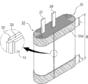
Fig. 7 is the decomposition diagram of the secondary cell that comprises electrode assemblie according to an aspect of the present invention.
Embodiment
Now will be at length with reference to present embodiment of the present invention, its example shown in the drawings, wherein, identical label is represented components identical all the time.Below through embodiment being described, with explanation the present invention with reference to accompanying drawing.Yet many aspects of the present invention can be implemented with multiple different form, should not be understood that to be confined to embodiment described here.To make the disclosure be completely and complete and provide these embodiment, and many aspects of the present invention are conveyed to those skilled in the art fully.In the accompanying drawings, for the sake of clarity, can exaggerate the layer with the zone thickness.It is also understood that when layer be known as " " another layer or substrate " on " time, this layer can be directly in another layer or substrate, or also can have the intermediate layer.
Fig. 1 is the cutaway view of termination zone 30 according to an aspect of the present invention.With reference to Fig. 1, termination zone 30 comprises rete 32 and adhesive phase 31.Rete 32 can be formed by the fluoropolymer resin such as polyethylene, polystyrene, polypropylene or PET (PET).In addition, adhesive phase 31 can be arranged on the basal surface of rete 32, thereby rete 32 is attached to the outmost surface of electrode assemblie (not shown in Fig. 1).For example, adhesive phase 31 can be formed by natural rubber, acrylic resin, polyurethanes or polyester.Yet the rete 32 of many aspects is not limited to above-mentioned material with adhesive phase 31 according to the present invention, because other suitable material is well-known to those skilled in the art, so will omit the detailed description to it here.
The termination zone 30 of many aspects can have about 19 μ m or littler thickness according to the present invention.Therefore, different with the traditional secondary battery that uses thicker termination zone, the surplus (that is, the zone between jar and the electrode assemblie) of the internal capacity of jar can be provided, thereby permit in jar, injecting the electrolyte of additional quantity.
In addition, the termination zone 30 of many aspects can have about 15 μ m or bigger thickness according to the present invention.This is because because current technical limitation is difficult to produce the termination zone of thickness less than 15 μ m.Therefore, although the surplus of the internal capacity that expectation thickness will make jar less than the termination zone of 15 μ m further increases, when thickness invested the coiling end of electrode assemblie less than the termination zone of about 15 μ m, termination zone was understood owing to thickness is too little and damaged.Therefore, used thickness will be difficult to fastening effectively electrode assemblie less than the termination zone of about 15 μ m, and be difficult to prevent effectively that electrode assemblie is loose.
Following table 1 illustrates the additional quantity that can be injected into the electrolyte in the jar owing to the reducing of thickness of termination zone with numeral.In table 1, suppose when termination zone coiling entire electrode assembly, to measure the volume of termination zone, like what below will describe with reference to Fig. 6.In addition, in table 1, used thickness is that the termination zone of about 22 μ m is as being used to calculate the volume decrease of termination zone and being used for the reference of additional quantity of electrolyte that thickness is respectively the termination zone of about 19 μ m and about 15 μ m.
Table 1
| The thickness of termination zone (μ m) | 22 | 19 | 15 |
| The volume of termination zone (cc) | 0.066 | 0.057 | 0.045 |
| The volume decrease (cc) of termination zone | - | 0.009 | 0.021 |
| The additional quantity of electrolyte (g) | - | 0.01 | 0.03 |
With reference to table 1, when the thickness of termination zone is respectively about 19 μ m and about 15 μ m, to compare when being about 22 μ m with the thickness of termination zone, the volume of termination zone has reduced nearly 0.009cc and 0.021cc respectively.When the density of electrolyte is about 1.227g/cc, and when the volume of termination zone has reduced respectively to reach 0.009cc and 0.021cc, can in jar, inject the electrolyte of 0.01g additional quantity and the electrolyte of 0.03g additional quantity.
Yet though because the adding of above-mentioned electrolyte can form high-capacity secondary battery, the thickness increase that the capacity of secondary cell increases the secondary cell that causes possibly have problems.That is, the formation of high-capacity secondary battery relates to the amount that under the situation of the volume that does not increase jar, increases electrolyte.In addition, in order to ensure the predetermined life-span, also should under the situation of the volume that does not increase jar, increase the amount of both positive and negative polarity active material.Yet for example, the inorganic particle that in negative active core-shell material, comprises can store lithium owing to charging, makes the volume of inorganic particle to expand.Along with the amount increase of both positive and negative polarity active material, the volumetric expansion meeting increases.This can cause secondary cell thickness when charging to increase.
Therefore, need prevent that secondary cell thickness when charging from increasing.In order to realize this purpose, the termination zone 30 of many aspects can preferably satisfy following formula 1 according to the present invention, when the hot strength of termination zone 30 is used kgf/cm
2Expression, the thickness of termination zone 30 is represented with μ m, and the modulus of elasticity of termination zone 30 is used kgf/mm
2During expression, the scope of Y1 can be preferably 64 to 89:

Alternatively, can preferably satisfy following formula 2, when the hot strength of termination zone 30 is used kgf/cm according to termination zone of the present invention
2Expression, the thickness of the rete 32 of termination zone 30 is represented with μ m, and the modulus of elasticity of termination zone 30 is used kgf/mm
2During expression, the scope of Y2 can be preferably 51 to 75:

When Y1 or Y2 depart from above-mentioned scope, can not reduce the thickness of secondary cell when charging effectively.Specifically, will describe like the back, when Y1 less than 64 or Y2 less than 51 the time, compare with the thickness of traditional battery, can not reduce the thickness of secondary cell when charging effectively.
Fig. 2 to Fig. 6 is the perspective view of different shape of termination zone 30a, 30b, 30c, 30d and the 30e of the many aspects according to the present invention.
Fig. 2 is the perspective view of termination zone 30a according to an aspect of the present invention.With reference to Fig. 2, electrode assemblie 10 comprises electrode group (electrode group) 20, and electrode group 20 comprises first battery lead plate 21, barrier film 23 and second battery lead plate 25 that sequentially piles up and reel.
First battery lead plate 21 and second battery lead plate 25 can be through forming applying positive electrode active materials on the plus plate current-collecting body and on negative current collector, apply negative active core-shell material respectively, thereby first battery lead plate 21 and second battery lead plate 25 have different polarities.In first battery lead plate 21 and second battery lead plate 25 each can have uncoated part, on uncoated part, do not apply positive electrode active materials or negative active core-shell material.First electrode tabs 27 and second electrode tabs 29 can invest the uncoated part of first battery lead plate 21 and the uncoated part of second battery lead plate 25 respectively, thereby can conduct electricity.
When in first battery lead plate 21 and second battery lead plate 25 any one is positive plate, can uses lithium transition-metal oxide as positive electrode active materials, and can use the plate that forms by aluminium as plus plate current-collecting body.When in first battery lead plate 21 and second battery lead plate 25 any one is negative plate, can uses carbon and carbon composite as negative active core-shell material, and can use the plate that forms by copper as negative current collector.Barrier film 23 prevents between first battery lead plate 21 and second battery lead plate 25, electrical short to take place.Barrier film 23 can be the porous layer that is formed by the polyolefin resin such as polyethylene or polypropylene.Yet the both positive and negative polarity active material of many aspects, both positive and negative polarity collector and barrier film 23 are not limited to above-mentioned material according to the present invention, because other suitable material is well-known to those skilled in the art, so will omit the detailed description to it here.
Though Fig. 2 illustrates first battery lead plate 21 and is arranged on the outside of electrode group 20, alternatively can second battery lead plate 25 be arranged on the outside of electrode group.
In the coiling end of electrode group 20, the coiling end of barrier film 23 can be more outstanding than the coiling end of each battery lead plate in first battery lead plate 21 and second battery lead plate 25, and be exposed.That is, because the end of barrier film 23 is exposed, so the end of barrier film 23 can become the essence end of electrode group 20.
Alternatively, though not shown in Fig. 2, the coiling end of first battery lead plate 21 can more outwards be given prominence to than the coiling end of barrier film 23 or the coiling end of second battery lead plate 25, and is exposed.In this case, the end of first battery lead plate 21 can become the essence end of electrode group 20.In addition, though not shown in Fig. 2, the coiling end of second battery lead plate 25 can more outwards be given prominence to than the coiling end of barrier film 23 or the coiling end of first battery lead plate 21, and is exposed.In this case, the end of second battery lead plate 25 can become the essence end of electrode group 20.
Because electrode assemblie 10 has winding form, so electrode assemblie 10 is tending towards loose owing to himself elasticity.Loose in order to prevent electrode assemblie 10, when termination zone 30a had about 15 μ m to the thickness of about 19 μ m, termination zone 30a should have at least 25% length L of about 10mm or bigger width W and the overall height H that equals electrode assemblie 10.When termination zone 30a had about 10mm or bigger width W, two parts of dividing along the Width of the coiling end of first battery lead plate 21 all can have about 5mm or bigger width.
Here, only define the lower limit of width W and the length L of termination zone 30a, because many aspects of the present invention are intended to make the zone that is occupied by termination zone 30a to minimize.In other words, when the width W of the termination zone 30a of the many aspects according to the present invention and length L were in above-mentioned lower limit, termination zone 30a is fixed electrode assembly 10 effectively.Therefore, the lower limit of the width W of termination zone 30a and length L with make that termination zone 30a can fastening effectively electrode assemblie 10 and to have the value of Minimum Area corresponding.
Fig. 3 is the perspective view of termination zone 30b according to a further aspect of the invention.Except described in the following description, the shape of the termination zone 30b of Fig. 3 is identical with the shape of the termination zone 30a of Fig. 2.With reference to Fig. 3, different with the termination zone 30a of Fig. 2, termination zone 30b invests the upper and lower of electrode group 20 ends respectively.That is, shown in Fig. 2 is the single termination zone 30a that invests the end of electrode group 20, and shown in Fig. 3 is two termination zone 30b that invest the end of electrode group 20.
The size of each termination zone 30b should meet the following conditions at least.That is, each termination zone 30b should have about 10mm or bigger width W, the length L of termination zone 30b 1 and L2 with (L1+L2) should be electrode assemblie 10 overall height H at least 25%.The size of termination zone 30b should satisfy above-mentioned condition so that thickness range be about 15 μ m can fastening electrode assemblie 10 to the termination zone 30b of about 19 μ m, and prevent that electrode assemblie 10 is loose.
Alternatively, though not shown in Fig. 3, can make n termination zone (n is a natural number) invest the end of electrode group 20.In this case, each termination zone 30b should have about 10mm or bigger width W, the length of each termination zone 30b with (L1+L2+L3+...+Ln) should be electrode assemblie 10 overall height H at least 25%.
Fig. 4 is the perspective view of termination zone 30c according to a further aspect of the invention.Except described in the following description, the shape of the termination zone 30c of Fig. 4 is identical with the shape of the termination zone 30a of Fig. 2.With reference to Fig. 4, different with the termination zone 30a of Fig. 2, termination zone 30c invests the whole end of electrode group 20.That is, termination zone 30c has about 10mm or bigger width W and the length L that equals the overall height H of electrode assemblie 10.Compare with the termination zone 30a of Fig. 2, the zone that is occupied by termination zone 30c increases, but that electrode assemblie 10 is terminated band 30c is more effectively fastening.
Fig. 5 is the perspective view of termination zone 30d according to a further aspect of the invention.Except described in the following description, the shape of the termination zone 30d of Fig. 5 is identical with the shape of the termination zone 30b of Fig. 3.With reference to Fig. 5, different with the termination zone 30b of Fig. 3, termination zone 30d invests the whole outer surface of presumptive area of the end that comprises electrode group 20 of electrode group 20 along the coiling direction of electrode group 20, and wraps in around the whole outer surface of electrode group 20.The length of each termination zone 30d with (L1+L2) be electrode assemblie 10 total length H at least 25%.In addition, the width W of each termination zone 30d can make the whole outside of each termination zone 30d rolled electrode group 20.Compare with the termination zone 30b of Fig. 3, the zone that is occupied by each termination zone 30d increases, but that electrode assemblie 10 is terminated band 30d is more effectively fastening.
Fig. 6 is the perspective view of termination zone 30e according to a further aspect of the invention.Except described in the following description, the shape of the termination zone 30e of Fig. 6 can be identical with the shape of the termination zone 30a of Fig. 2.With reference to Fig. 6, different with the termination zone 30a of Fig. 2, termination zone 30e invests the whole outer surface of the whole end that comprises electrode group 20 of electrode group 20, and along the whole outer surface of the coiling direction rolled electrode group 20 of electrode group 20.Compare with the termination zone 30a of Fig. 2, the zone that is occupied by the termination zone 30e of Fig. 6 increases, but electrode assemblie 10 is by more effectively fastening, and can prevent the volumetric expansion of electrode assemblie 10 most effectively.Promptly; Because compare with the arbitrary termination zone among the termination zone 30a to 30d of Fig. 2 to Fig. 5; The termination zone 30e of Fig. 6 occupies bigger zone; Only can in jar, inject the electrolyte of minimum additional quantity, but termination zone 30e coiling entire electrode assembly 10, thereby can prevent the volumetric expansion of electrode assemblie 10 most effectively.
Fig. 7 is the decomposition diagram of the secondary cell that comprises electrode assemblie 10 according to an aspect of the present invention.With reference to Fig. 7, secondary cell comprises electrode assemblie 10, be used for the shell 50 of hold electrodes assembly 10 and be used to cover the cap assemblies 70 of shell 50.Electrode assemblie 10 has any structure of describing with reference to Fig. 2 to Fig. 6, and is contained in the shell 50, but in Fig. 7, is shown the termination zone 30e with Fig. 6.The shell 50 of hold electrodes assembly 10 has the opening 51 that is formed on the one of which end.After being contained in electrode assemblie 10 in the shell 50, cap assemblies 70 being inserted in the opening 51, thereby shell 50 is covered.Secondary cell also comprises the electrolyte that is injected in the shell 50.Secondary cell has thickness as shown in Figure 7 (t).
Electrolyte can comprise any non-aqueous organic solvent.Non-aqueous organic solvent can be carbonic ester, ester, ether or ketone.Carbonic ester can be dimethyl carbonate (DMC), diethyl carbonate (DEC), dipropyl carbonate (DPC), carbonic acid first propyl ester (MPC), ethyl propyl carbonic acid ester (EPC), methyl ethyl carbonate (MEC), ethylene carbonate (EC), isobutyl carbonate third rare ester (PC) or butylene (BC).Ester can be butyrolactone (BL), decalactone (decanolide), valerolactone, mevalonolactone (mevalonolactone), caprolactone (caprolactone), methyl acetate, ethyl acetate or n-propyl acetate.Ether can be butyl oxide.Ketone can be to gather methyl vinyl ketone.Yet many aspects of the present invention are not limited to above-mentioned non-aqueous organic solvent, because other suitable non-aqueous organic solvent is well-known to those skilled in the art, so will omit the detailed description to it here.
In addition, can comprise lithium salts according to electrolyte of the present invention, lithium salts is as the source of lithium ion, and can make lithium rechargeable battery carry out basic operation.For example, lithium salts can comprise from by LiPF
6, LiBF
4, LiSbF
6, LiAsF
6, LiClO
4, LiCF
3SO
3, LiN (CF
3SO
2)
2, LiN (C
2F
5SO
2)
2, LiAlO
4, LiAlCl
4, LiN (C
xF
2x+1SO
2) (C
yF
2y+1SO
2) (x and y are natural numbers), LiSO
3CF
3That selects in the group of forming with their mixture is at least a.Yet many aspects of the present invention are not limited to above-mentioned lithium salts, because other suitable lithium salts is well-known to those skilled in the art, so will omit the detailed description to it here.
Yet many aspects of the present invention are not limited to above-mentioned electrolyte, because other suitable electrolyte is well-known to those skilled in the art, so will omit the detailed description to it here.
The secondary cell of many aspects can be made according to above-mentioned technology according to the present invention.Yet many aspects of the present invention are not limited to the secondary cell of mentioned kind.
The embodiment and the comparative examples of the many aspects according to the present invention will be described now.Yet, according to many aspects of the present invention following experimental example only being provided, many aspects of the present invention are not limited thereto.
Example 1
Will be as the LiCoO of positive electrode active materials
2, mix with 92: 4: 4 weight ratio as the polyvinylidene fluoride (PVDF) of adhesive with as the carbon of conductive agent, and be dispersed in the N-N-methyl-2-2-pyrrolidone N-, produce anodal slurry thus.The positive pole slurry is coated on the thick aluminium foil of 20 μ m, drying, and rolling, thus form anodal.Will be as the artificial blacklead (black lead) of negative active core-shell material, mix with 96: 2: 2 weight ratio as the styrene-butadiene resin of adhesive with as the carboxymethyl cellulose (CMC) of tackifier, and be dispersed in the water, produce slurry thus.Slurry is coated on the thick Copper Foil of 15 μ m, and drying, and rolling are to form negative pole.To be arranged between positive pole and the negative pole by the thick barrier film of 20 μ m that polyethylene (PE) forms.Septate positive pole and negative pole coiling and compression will be set therebetween,, and be inserted in the prismatic jar with the formation electrode assemblie.Then, inject the electrolyte in the prismatic jar, make lithium secondary battery thus.Compare with comparative examples 1, further add the electrolyte of 0.03g additional quantity.In addition, the thick termination zone of 15 μ m is invested the coiling end of electrode assemblie, thereby keep electrode assemblie to be in reeling condition.In addition, as shown in Figure 6, when termination zone 30e was invested electrode assemblie 10, termination zone wrapped in around the whole outer surface of the whole coiling end that comprises electrode assemblie of electrode assemblie.Termination zone comprises rete and adhesive phase.Rete is thick PET (PET) layers of 12 μ m, and adhesive phase is the thick acryloid cement layers of 3 μ m.
Example 2
Use the thick pet layer of 16 μ m as rete, and compare, further add the electrolyte of 0.01g additional quantity, in addition, carry out the technology identical with example 1 with comparative examples 1.
Comparative examples 1
Except using the thick pet layer of 19 μ m, carry out the technology identical with example 1 as the rete.
Comparative examples 2
Use the thick polypropylene (PP) of 25 μ m layer as rete, and use the thick acryloid cement layer of 5 μ m, in addition, carry out the technology identical with example 1 as adhesive phase.
Measurement is according to hot strength and the modulus of elasticity of example 1 with example 2 and the comparative examples 1 and the termination zone of the lithium secondary battery of comparative examples 2 manufacturings; According to top formula of listing 1 and formula 2, based on hot strength and the modulus of elasticity acquisition value Y1 and the Y2 of the termination zone of measuring.In addition, measure the thickness of lithium secondary battery when going out lotus charging (ship-charged) (or half charging) and charging fully according to example 1 and example 2 and comparative examples 1 and comparative examples 2 manufacturings, as shown in table 2.
Table 2

With reference to table 2, when as in comparative examples 1 and 2, Y1 surpass 89 and Y2 surpass at 75 o'clock, can find out the thickness of the thickness of secondary cell when going out the lotus charging and charging fully in the example 2.In addition, when Y1 in like example 1 is 64 and Y2 when being 51, can find out that the thickness of secondary cell when going out the lotus charging and charging fully is greater than the thickness in the example 2 and less than the thickness in comparative examples 1 and 2.In addition, because because current technical limitation is difficult to make the termination zone of thickness less than about 15 μ m, so can not obtain thickness at termination zone less than value Y1 under the situation of 15 μ m and Y2.Yet when estimating that thickness when termination zone is less than 15 μ m, being worth Y1 and Y2 will be less than the value in the example 1.
Yet according to the data analysis to example 1 and comparative examples 1, when estimating that Y1 on duty and Y2 are too small, the thickness of lithium secondary battery when going out the lotus charging and charging fully will demonstrate the trend of increase.Therefore, when Y1 less than 64 and/or Y2 less than 51 the time, estimate to compare with comparative examples 1, the thickness of lithium secondary battery when going out the lotus charging and charging fully will reduce even increase hardly.
Therefore, the formula 1 that the termination zone of many aspects is listed above preferably satisfying according to the present invention, Y1 is preferably 64 to 89 scope.Alternatively, the formula 2 that the termination zone of many aspects is listed above preferably satisfying according to the present invention, Y2 is preferably 51 to 75 scope.
That is, when Y1 or Y2 depart from above-mentioned scope, can not reduce the thickness of secondary cell when charging effectively.Specifically, when Y1 less than 64 or Y2 less than 51 the time, compare with traditional situation, can not reduce the thickness of secondary cell when charging effectively.
Therefore, the thickness of the termination zone of many aspects of the present invention through reducing electrode assemblie provides high-capacity secondary battery.In addition, this termination zone can prevent the increase of the thickness of high-capacity secondary battery effectively.
Though illustrated and described embodiments of the invention; But it will be appreciated by those skilled in the art that; Under the situation that does not break away from principle of the present invention and spirit, can in these embodiment, make a change, scope of the present invention is limited claim and equivalent thereof.
Claims (22)
1. electrode assemblie, said electrode assemblie comprises:
Electrode group, said electrode group comprise first battery lead plate, barrier film and second battery lead plate that sequentially piles up and reel;
Termination zone, said termination zone invests the presumptive area of the end of said electrode group,
Wherein, said termination zone satisfies following formula, when the hot strength of said termination zone is used kgf/cm
2Expression, the thickness of said termination zone is represented with μ m, and the modulus of elasticity of said termination zone is used kgf/mm
2During expression, the scope of Y1 is 64 to 89:

2. electrode assemblie according to claim 1, wherein, the thickness of said termination zone is 15 μ m to 19 μ m.
3. electrode assemblie according to claim 1, wherein, said termination zone has at least 25% length along the 10mm of the coiling direction of said electrode group or bigger width and the total height that equals said electrode assemblie.
4. electrode assemblie according to claim 1; Wherein, Said termination zone is one that invests respectively in two termination zones of upper and lower of said electrode group; In the said termination zone each has along the 10mm of the coiling direction of said electrode group or bigger width, at least 25% of the total height length of said two termination zones and that equal said electrode assemblie.
5. electrode assemblie according to claim 1, wherein, said termination zone has along the 10mm of the coiling direction of said electrode group or bigger width and the length that equals the total height of said electrode assemblie.
6. electrode assemblie according to claim 1; Wherein, Said termination zone is one that invests respectively in two termination zones of upper and lower of said electrode group; At least 25% of the total height length of said two termination zones and that equal said electrode assemblie, the width of the coiling direction of the said electrode group in edge of each termination zone in said two termination zones can make the coiling direction of each the said electrode group in termination zone edge in said two termination zones wrap in around the whole outer surface of said electrode group.
7. electrode assemblie according to claim 1; Wherein, Said termination zone has the length of the total height that equals said electrode assemblie, and the width of the coiling direction of the said electrode group in the edge of said termination zone can make said termination zone wrap in around the whole outer surface of said electrode group along the coiling direction of said electrode group.
8. electrode assemblie according to claim 1, wherein, said termination zone comprises rete and adhesive phase, and satisfies following formula, when the hot strength of said termination zone is used kgf/cm
2Expression, the thickness of said termination zone is represented with μ m, and the modulus of elasticity of said termination zone is used kgf/mm
2During expression, the scope of Y2 is 51 to 75:

9. electrode assemblie, said electrode assemblie comprises:
Electrode group, said electrode group comprise first battery lead plate, barrier film and second battery lead plate that sequentially piles up and reel;
Termination zone, said termination zone invests the presumptive area of the end of said electrode group;
Wherein, said termination zone comprises rete and adhesive phase, and satisfies following formula, when the hot strength of said termination zone is used kgf/cm
2Expression, the thickness of said termination zone is represented with μ m, and the modulus of elasticity of said termination zone is used kgf/mm
2During expression, the scope of Y2 is 51 to 75:

10. electrode assemblie according to claim 9, wherein, the thickness of said termination zone is 15 μ m to 19 μ m.
11. electrode assemblie according to claim 9, wherein, said termination zone has at least 25% length along the 10mm of the coiling direction of said electrode group or bigger width and the total height that equals said electrode assemblie.
12. electrode assemblie according to claim 9; Wherein, Said termination zone is one that invests respectively in two termination zones of upper and lower of said electrode group; In the said termination zone each has along the 10mm of the coiling direction of said electrode group or bigger width, at least 25% of the total height length of said two termination zones and that equal said electrode assemblie.
13. electrode assemblie according to claim 9, wherein, said termination zone has along the 10mm of the coiling direction of said electrode group or bigger width and the length that equals the total height of said electrode assemblie.
14. electrode assemblie according to claim 9; Wherein, Said termination zone is one that invests respectively in two termination zones of upper and lower of said electrode group; At least 25% of the total height length of said two termination zones and that equal said electrode assemblie, the width of the coiling direction of the said electrode group in edge of each termination zone in said two termination zones can make the coiling direction of each the said electrode group in termination zone edge in said two termination zones wrap in around the whole outer surface of said electrode group.
15. electrode assemblie according to claim 9; Wherein, Said termination zone has the length of the total height that equals said electrode assemblie, and the width of the coiling direction of the said electrode group in the edge of said termination zone can make said termination zone wrap in around the whole outer surface of said electrode group along the coiling direction of said electrode group.
16. a secondary cell, said secondary cell comprises:
Electrode assemblie, said electrode assemblie comprises electrode group and termination zone, and said electrode group comprises first battery lead plate, barrier film and second battery lead plate that sequentially piles up and reel, and said termination zone invests the presumptive area of the end of said electrode group;
Shell, said shell has the electrode assemblie that is arranged on wherein;
Electrolyte, said electrolyte are injected in the surplus between said shell and the said electrode assemblie,
Wherein, said termination zone satisfies following formula, when the hot strength of said termination zone is used kgf/cm
2Expression, the thickness of said termination zone is represented with μ m, and the modulus of elasticity of said termination zone is used kgf/mm
2During expression, the scope of Y1 is 64 to 89:

17. secondary cell according to claim 16, wherein, the thickness of said termination zone is 15 μ m to 19 μ m.
18. secondary cell according to claim 16, wherein, said termination zone has at least 25% length along the 10mm of the coiling direction of said electrode group or bigger width and the total height that equals said electrode assemblie.
19. secondary cell according to claim 16, wherein, said termination zone comprises rete and adhesive phase, and satisfies following formula, when the hot strength of said termination zone is used kgf/cm
2Expression, the thickness of said termination zone is represented with μ m, and the modulus of elasticity of said termination zone is used kgf/mm
2During expression, the scope of Y2 is 51 to 75:

20. a secondary cell, said secondary cell comprises:
Electrode assemblie, said electrode assemblie comprises electrode group and termination zone, and said electrode group comprises first battery lead plate, barrier film and second battery lead plate that sequentially piles up and reel, and said termination zone invests the presumptive area of the end of said electrode group;
Shell, said shell has the electrode assemblie that is arranged on wherein;
Electrolyte, said electrolyte are injected in the surplus between said shell and the said electrode assemblie;
Wherein, said termination zone comprises rete and adhesive phase, and satisfies following formula, when the hot strength of said termination zone is used kgf/cm
2Expression, the thickness of said termination zone is represented with μ m, and the modulus of elasticity of said termination zone is used kgf/mm
2During expression, the scope of Y2 is 51 to 75:

21. secondary cell according to claim 20, wherein, the thickness of said termination zone is 15 μ m to 19 μ m.
22. secondary cell according to claim 20, wherein, said termination zone has at least 25% length along the 10mm of the coiling direction of said electrode group or bigger width and the total height that equals said electrode assemblie.
Applications Claiming Priority (2)
| Application Number | Priority Date | Filing Date | Title |
|---|---|---|---|
| KR10-2009-0049930 | 2009-06-05 | ||
| KR1020090049930A KR101118259B1 (en) | 2009-06-05 | 2009-06-05 | Electrode assembly and secondary battery using the same |
Publications (2)
| Publication Number | Publication Date |
|---|---|
| CN101908613A CN101908613A (en) | 2010-12-08 |
| CN101908613B true CN101908613B (en) | 2012-11-14 |
Family
ID=42651073
Family Applications (1)
| Application Number | Title | Priority Date | Filing Date |
|---|---|---|---|
| CN2010101928940A Active CN101908613B (en) | 2009-06-05 | 2010-05-28 | Electrode assembly and secondary battery using the same |
Country Status (5)
| Country | Link |
|---|---|
| US (1) | US8283064B2 (en) |
| EP (1) | EP2267830B1 (en) |
| JP (1) | JP2010282945A (en) |
| KR (1) | KR101118259B1 (en) |
| CN (1) | CN101908613B (en) |
Families Citing this family (19)
| Publication number | Priority date | Publication date | Assignee | Title |
|---|---|---|---|---|
| KR101040826B1 (en) * | 2009-09-28 | 2011-06-14 | 삼성에스디아이 주식회사 | Secondary battery |
| KR101049011B1 (en) * | 2009-10-06 | 2011-07-12 | 삼성에스디아이 주식회사 | Secondary Battery and Manufacturing Method Thereof |
| JP2012069290A (en) * | 2010-09-21 | 2012-04-05 | Toyota Motor Corp | Secondary battery, vehicle, and device using battery |
| CN102751464B (en) * | 2011-12-30 | 2015-09-09 | 东莞新能德科技有限公司 | A kind of battery pack and preparation method thereof |
| KR102050862B1 (en) * | 2012-11-16 | 2019-12-02 | 에스케이이노베이션 주식회사 | Secondary battery |
| US10014495B2 (en) | 2013-05-15 | 2018-07-03 | Samsung Sdi Co., Ltd. | Rechargeable battery |
| KR102121737B1 (en) | 2013-10-16 | 2020-06-11 | 삼성에스디아이 주식회사 | Secondary Battery |
| JP6221819B2 (en) * | 2014-02-25 | 2017-11-01 | 株式会社豊田自動織機 | Power storage device |
| KR102275638B1 (en) * | 2014-11-19 | 2021-07-09 | 삼성에스디아이 주식회사 | Rechargeable battery |
| KR102534101B1 (en) * | 2015-11-12 | 2023-05-18 | 삼성에스디아이 주식회사 | Secondary battery |
| KR102142673B1 (en) * | 2016-03-04 | 2020-08-07 | 주식회사 엘지화학 | A electrode assembly and a pouch type cell comprising the same |
| WO2018105398A1 (en) * | 2016-12-05 | 2018-06-14 | 三洋電機株式会社 | Cylindrical nonaqueous electrolyte secondary battery |
| KR102248104B1 (en) * | 2017-10-11 | 2021-05-03 | 주식회사 엘지화학 | Battery Cell Comprising Sealing Tape for Accelerating Heat Conduction |
| JP7004206B2 (en) * | 2017-12-22 | 2022-01-21 | トヨタ自動車株式会社 | Batteries assembled |
| US11450893B2 (en) * | 2018-06-20 | 2022-09-20 | Sanyo Electric Co., Ltd. | Nonaqueous electrolyte secondary battery |
| CN110190339A (en) * | 2019-03-01 | 2019-08-30 | 青海时代新能源科技有限公司 | Secondary cell |
| US11552354B2 (en) * | 2019-07-08 | 2023-01-10 | Jiangsu Contemporary Amperex Technology Limited | Secondary battery |
| CN112771698B (en) * | 2020-03-10 | 2022-02-22 | 宁德新能源科技有限公司 | Battery cell and battery with same |
| US20220115712A1 (en) * | 2020-05-20 | 2022-04-14 | Ningde Amperex Technology Limited | Electrode assembly and battery |
Family Cites Families (13)
| Publication number | Priority date | Publication date | Assignee | Title |
|---|---|---|---|---|
| JPH11297349A (en) | 1998-04-09 | 1999-10-29 | Nitto Denko Corp | Adhesive tape or sheet for battery |
| JP2000144074A (en) * | 1998-11-11 | 2000-05-26 | Nitto Denko Corp | Windable insulating adhesive tape or sheet |
| JP3851153B2 (en) | 2001-11-30 | 2006-11-29 | 三洋電機株式会社 | Battery and manufacturing method thereof |
| JP4558279B2 (en) | 2003-02-21 | 2010-10-06 | パナソニック株式会社 | Square battery and method for manufacturing the same |
| KR100530158B1 (en) | 2003-10-15 | 2005-11-21 | 삼성에스디아이 주식회사 | Jelly Roll with Seprate Support Tape in Secondary Battery |
| KR100686851B1 (en) | 2005-05-30 | 2007-02-26 | 삼성에스디아이 주식회사 | Composite Material Tape for Lithium Secondary battery and Lithium Secondary battery using the Same |
| ATE415712T1 (en) * | 2004-09-22 | 2008-12-15 | Samsung Sdi Co Ltd | COMPOSITE MATERIAL TAPE FOR SECONDARY LITHIUM BATTERIES AND SECONDARY LITHIUM BATTERIES USING THIS |
| KR100686813B1 (en) * | 2005-04-26 | 2007-02-26 | 삼성에스디아이 주식회사 | Secondary Battery |
| KR101174990B1 (en) | 2005-09-05 | 2012-08-17 | 삼성에스디아이 주식회사 | Electrode assembly of secondary battery and secondary battery therewith |
| KR20070087857A (en) * | 2005-12-29 | 2007-08-29 | 삼성에스디아이 주식회사 | Lithium rechargeable battery |
| JP2007242518A (en) * | 2006-03-10 | 2007-09-20 | Sanyo Electric Co Ltd | Square battery |
| KR101285977B1 (en) | 2006-04-10 | 2013-07-12 | 삼성에스디아이 주식회사 | Eletrode assembly and secondary battery having the same |
| KR20080047153A (en) | 2006-11-24 | 2008-05-28 | 삼성에스디아이 주식회사 | Secondary battery |
-
2009
- 2009-06-05 KR KR1020090049930A patent/KR101118259B1/en active IP Right Grant
- 2009-07-30 JP JP2009177823A patent/JP2010282945A/en active Pending
-
2010
- 2010-05-28 CN CN2010101928940A patent/CN101908613B/en active Active
- 2010-05-28 US US12/789,654 patent/US8283064B2/en active Active
- 2010-05-28 EP EP10164392A patent/EP2267830B1/en active Active
Non-Patent Citations (3)
| Title |
|---|
| JP特开2000-144074A 2000.05.26 |
| JP特开2007-242518A 2007.09.20 |
| JP特开平11-297349A 1999.10.29 |
Also Published As
| Publication number | Publication date |
|---|---|
| US8283064B2 (en) | 2012-10-09 |
| CN101908613A (en) | 2010-12-08 |
| EP2267830B1 (en) | 2012-07-25 |
| US20100310912A1 (en) | 2010-12-09 |
| EP2267830A1 (en) | 2010-12-29 |
| JP2010282945A (en) | 2010-12-16 |
| KR101118259B1 (en) | 2012-03-20 |
| KR20100131166A (en) | 2010-12-15 |
Similar Documents
| Publication | Publication Date | Title |
|---|---|---|
| CN101908613B (en) | Electrode assembly and secondary battery using the same | |
| CN101202362B (en) | Rechargeable lithium battery | |
| CN101373851B (en) | Non-aqueous electrolytic solution secondary battery | |
| CN100433440C (en) | High power lithium ion cell | |
| US11646415B2 (en) | Secondary battery, battery module, battery pack, apparatus containing the secondary battery | |
| CN101154753B (en) | Non-aqueous electrolyte secondary cell | |
| CN101286572A (en) | Nummular non-aqueous electrolyte secondary battery | |
| US20060240290A1 (en) | High rate pulsed battery | |
| CN104011924A (en) | Nonaqueous electrolyte secondary battery | |
| CN101714651A (en) | Secondary battery | |
| CN103887470A (en) | Nonaqueous electrolyte battery and battery pack | |
| KR20080082276A (en) | Electrolyte for rechargeable lithium battery and rechargeable lithium battery comprising same | |
| CN102005561A (en) | Positive electrode for nonaqueous electrolyte secondary battery and nonaqueous electrolyte secondary battery using the same | |
| CN103326013A (en) | Nonaqueous electrolyte battery and battery pack | |
| US11271250B2 (en) | Lithium ion secondary battery | |
| CN112909220A (en) | Secondary battery and device containing the same | |
| CN101950800A (en) | Electrode assemblie and lithium secondary battery with this electrode assemblie | |
| CN102694176A (en) | Electrode for non-aqueous electrolyte battery, and non-aqueous electrolyte battery using the electrode | |
| CN106229587A (en) | Lithium battery pack and the forming method of high discharge pulse can be provided in wide temperature range | |
| EP4020627A1 (en) | Device for pre-lithiation of negative electrode and method for pre-lithiation of negative electrode | |
| EP2879225B1 (en) | Electric storage device and electric storage apparatus | |
| CN204204956U (en) | Active material for battery body, electrode, nonaqueous electrolyte battery and power brick | |
| CN104508891A (en) | Non-aqueous electrolyte secondary cell | |
| EP4329014A1 (en) | Secondary battery, battery module comprising secondary battery, battery pack, and electric device | |
| CN109428125A (en) | The lithium ion electrochemical device in service life is improved with excessive electrolyte capacity |
Legal Events
| Date | Code | Title | Description |
|---|---|---|---|
| C06 | Publication | ||
| PB01 | Publication | ||
| C10 | Entry into substantive examination | ||
| SE01 | Entry into force of request for substantive examination | ||
| C14 | Grant of patent or utility model | ||
| GR01 | Patent grant |