CN101876226A - Lower box lock mechanism of combined tool cabinet - Google Patents
Lower box lock mechanism of combined tool cabinet Download PDFInfo
- Publication number
- CN101876226A CN101876226A CN2010101339170A CN201010133917A CN101876226A CN 101876226 A CN101876226 A CN 101876226A CN 2010101339170 A CN2010101339170 A CN 2010101339170A CN 201010133917 A CN201010133917 A CN 201010133917A CN 101876226 A CN101876226 A CN 101876226A
- Authority
- CN
- China
- Prior art keywords
- lock
- lower box
- drawer
- tool cabinet
- drawers
- Prior art date
- Legal status (The legal status is an assumption and is not a legal conclusion. Google has not performed a legal analysis and makes no representation as to the accuracy of the status listed.)
- Granted
Links
Images
Landscapes
- Drawers Of Furniture (AREA)
Abstract
The invention discloses a lower box lock mechanism of a combined tool cabinet. A plurality of slidable drawers are arranged in a lower box body, the lower box body is also provided with a locking mechanism which can lock all drawers at one time, and the locking mechanism comprises a rotating lever, a connecting-rod lock, a lock head which is arranged at the front end of the rotating lever and a key which is matched with the lock head; and a rotating hook capable of making the connecting-rod lock move up and own is fixed at the rear end of the rotating lever, the connecting-rod lock is provided with locking claws which are as many as the drawers and capable of locking the drawers, and the rear ends of the drawers are provided with clamping claws which are fastened with the locking claws. The lower box lock mechanism of the combined tool cabinet has the advantages that: the occupied space of the connecting-rod lock is saved, the multiple linkage locking of the drawers and in particular the pulling state control over a plurality of drawers are realized, and the use of people is convenient; by means of the fastening of the locking claws and the clamping claws, accident sliding of the drawers is effectively prevented, and the use safety of the drawers is further guaranteed; and the lower box lock mechanism of the combined tool cabinet has an attractive appearance, convenient operation and high safety and is worthy of popularization and use.
Description
Technical field
The present invention relates to a kind of lock bar linkage structure, what be specifically related to is a kind of lower box lock mechanism that is used in combined tool cabinet.
Background technology
General factory building staff is for work requirements and conveniently, all can in factory building, dispose a portable Tool Cabinet, the little drawer that many place tools are arranged arranged evenly in this Tool Cabinet, in order to repair thing, the user can conveniently classify in each little drawer according to its job requirements and place various hand-held tool, as spanner, bottle opener or various bolt part, yet, when Tool Cabinet is subjected to mass loading, and when cabinet move or earthquake when taking place side make easily then that drawer is improper to skid off the Tool Cabinet outside, unexpected dangerous generation is then caused on ground easily if the various hand-held tool article that drawer inside is put drop.
At present, occurring knockdown Tool Cabinet on the market, it is to be formed by upper and lower box body combinations.It is that latch lever locks simultaneously that a plurality of drawers in lower box adopt; Though solved the improper problem that skids off the Tool Cabinet outside of drawer, existing latch lever is that what to be fixed on drawer is the front portion of drawer in front of the door, and it takes up room, uses inconvenience, and the security performance of snap close is low, and influence the aesthetic property of Tool Cabinet inside.
Summary of the invention
In view of the deficiency on the prior art, the present invention seeks to be to provide a kind of syndeton of making the combined tool cabinet simple, easy to operate, that the snap close security performance is high.
To achieve these goals, technical scheme of the present invention is as follows:
A kind of lower box lock mechanism of combined tool cabinet comprises upper box and lower box, and described upper box and lower box are connected as a single entity structure; In described lower box, be provided with a plurality of slidably drawers, it is characterized in that: on described lower box, also be provided with a locked mechanism that locks each drawer simultaneously, described locked mechanism comprises dwang, lock connecting rod, be arranged on the dwang front end tapered end and with the suitable key of tapered end; Being fixed with the rotation that the lock connecting rod is moved up and down in described dwang rear end colludes, described lock connecting rod is provided with its quantity and drawer quantity Matching, and the lock pawl of the drawer that can lock, be provided with in the rear end of described drawer and lock the pawl of buckleing that pawl is interlocked, fasten mutually by lock pawl and button pawl, thereby realized the purpose that each drawer locks simultaneously, increased the aesthetic property of Tool Cabinet, guaranteed the safety of the use of drawer.
Further, described rotation is colluded and is " Z " shape structure, and is connected with the lock connecting rod by a fixed support, and make fixed support drive the lock connecting rod and move up and down, and then the fastening between control lock pawl and the button pawl, make it reach the purpose of unblanking and locking.
Further, described lock pawl is downward-sloping following tooth bar, and described button pawl is acclivitous upper rack, and described tooth bar down forms a lower bayonet slot that Open Side Down with the lock connecting rod, and described upper rack and drawer rear end face form the last draw-in groove that makes progress with opening; Move down by the lock connecting rod, tooth bar and upper rack are inserted respectively in draw-in groove and the lower bayonet slot, reach fastening then, each drawer is locked simultaneously.
Further, be provided with the lock core suitable with key in the described tapered end, described lock core rear end connects dwang.
Further, the rotational angle of described lock core in tapered end is 0~180 degree, can move reciprocatingly in 180 degree by tapered end control lock core.
The present invention is arranged on the rear end of drawer by locking connecting rod, has saved taking up room of lock connecting rod, has realized multiple chain to drawer, and especially many drawers extraction state control has made things convenient for people's use; And, prevented that effectively the drawer accidents happened to from skidding off by lock pawl and button being interlocked of pawl, and further having guaranteed the safe in utilization of drawer, it has good looking appearance, easy to operate and advantage that security performance is high, is worth of widely use.
Description of drawings
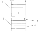
Fig. 1 is the structural representation of an embodiment combined tool cabinet.
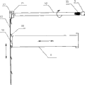
Fig. 2 is a structural representation of the present invention.
The specific embodiment
For technological means, creation characteristic that the present invention is realized, reach purpose and effect is easy to understand, below in conjunction with the specific embodiment, further set forth the present invention.
As depicted in figs. 1 and 2, the lower box lock mechanism of a kind of combined tool cabinet of the present invention, it comprises upper box 1 and lower box 2; This upper box 1 is an integral structure with lower box 2, is convenient for people to store the instrument of use, saves the usage space of Tool Cabinet.In described lower box 2, be provided with the locked mechanism 3 of a plurality of slidably drawers 4 and each drawer 4 that locks simultaneously; This locked mechanism 3 comprises dwang 32, lock connecting rod 35, be arranged on dwang 32 front ends tapered end 31 and with the suitable key 6 of tapered end 31; In tapered end 31, be provided with key 6 on the suitable lock core of lock tooth, the rear end of this lock core connects the front end of dwang 32, be fixed with the rotation that is " Z " shape structure in the rear end of dwang 32 and collude 33, this rotation is colluded 33 and is connected with lock connecting rod 35 by a fixed support 34, makes its drive lock connecting rod 35 and moves up and down.
Above-mentioned lock connecting rod 35 is mounted in drawer rear end in the lower box of combined tool cabinet, has saved the usage space of lock connecting rod 35, has increased the aesthetic property of drawer front end.On lock connecting rod 35, be provided with its quantity and drawer quantity Matching, and the lock pawl 36 of the drawer 4 that can lock, the rear end of each drawer 4 be provided with lock pawl 36 suitable buckle pawl 41, fasten mutually by lock pawl 36 and button pawl 41, thereby realized the purpose that each drawer locks simultaneously, increase the aesthetic property of Tool Cabinet, guaranteed the safety of the use of drawer.
In the present embodiment, described lock pawl 36 is downward-sloping following tooth bar, described button pawl 41 is acclivitous upper rack, and described tooth bar down forms a lower bayonet slot that Open Side Down with the lock connecting rod, and described upper rack and drawer rear end face form the last draw-in groove that makes progress with opening; Drive the lock connecting rod by turning cylinder and move up and down, tooth bar and upper rack are inserted respectively in draw-in groove and the lower bayonet slot, reach fastening then, each drawer 4 is locked simultaneously.
In addition, the rotational angle of above-mentioned lock core in tapered end 31 is 0~180 degree, can move reciprocatingly in 180 degree by tapered end 31 control lock cores.
Present embodiment in use, key 6 is inserted in the lock core, the key 6 that turns clockwise then drives the lock core rotation, thereby drive dwang 32 and collude 33 rotations with the rotation that is " Z " shape structure, drive lock connecting rods 35 and move downward colluding 33 by rotation, then the buckle pawl 41 of each lock pawl 36 with each drawer 4 rear end is interlocked, reached the purpose of each drawer 4 that locks simultaneously.
When needs are removed locking, in like manner, key 6 is inserted in the lock core, be rotated counterclockwise key 6, can drive lock connecting rod 35 and move upward, thereby make lock pawl 36 separate the purpose that reaches release with the button pawl.
Based on above-mentioned, the present invention is arranged on the rear end of drawer 4 by locking connecting rod 35, has saved taking up room of lock connecting rod 35, has realized multiple chain to drawer 4, and especially many drawer 4 extraction states controls have made things convenient for people's use; And, prevented that effectively drawer 4 accidents happened to from skidding off by being interlocked of lock pawl 36 and button pawl 41, and further having guaranteed the safe in utilization of drawer, it has good looking appearance, easy to operate and advantage that security performance is high, is worth of widely use.
More than show and described basic principle of the present invention and principal character and advantage of the present invention.The technician of the industry should understand; the present invention is not restricted to the described embodiments; that describes in the foregoing description and the manual just illustrates principle of the present invention; without departing from the spirit and scope of the present invention; the present invention also has various changes and modifications, and these changes and improvements all fall in the claimed scope of the invention.The claimed scope of the present invention is defined by appending claims and equivalent thereof.
Claims (5)
1. the lower box lock mechanism of a combined tool cabinet comprises upper box and lower box, and described upper box and lower box are connected as a single entity structure; In described lower box, be provided with a plurality of slidably drawers, it is characterized in that: on described lower box, also be provided with a locked mechanism that locks each drawer simultaneously, described locked mechanism comprises dwang, lock connecting rod, be arranged on the dwang front end tapered end and with the suitable key of tapered end; Be fixed with the rotation that the lock connecting rod is moved up and down in described dwang rear end and collude, described lock connecting rod is provided with its quantity and drawer quantity Matching, and the lock pawl of the drawer that can lock, and is provided with in the rear end of described drawer and locks the pawl of buckleing that pawl is interlocked.
2. Tool Cabinet according to claim 1 is characterized in that: described rotation is colluded and is " Z " shape structure, and described rotation was worked hard in glove with a fixed support and is connected with the lock connecting rod.
3. Tool Cabinet according to claim 1, it is characterized in that: described lock pawl is downward-sloping following tooth bar, described button pawl is acclivitous upper rack, described tooth bar down forms a lower bayonet slot that Open Side Down with the lock connecting rod, and described upper rack and drawer rear end face form the last draw-in groove that makes progress with opening; Described tooth bar down and upper rack can be inserted draw-in groove and lower bayonet slot respectively.
4. Tool Cabinet according to claim 1 is characterized in that: be provided with the lock core suitable with key in the described tapered end, described lock core rear end connects dwang.
5. Tool Cabinet according to claim 4 is characterized in that: the rotational angle of described lock core in tapered end is 0~180 degree.
Priority Applications (1)
| Application Number | Priority Date | Filing Date | Title |
|---|---|---|---|
| CN201010133917.0A CN101876226B (en) | 2010-03-26 | 2010-03-26 | Lower box lock mechanism of combined tool cabinet |
Applications Claiming Priority (1)
| Application Number | Priority Date | Filing Date | Title |
|---|---|---|---|
| CN201010133917.0A CN101876226B (en) | 2010-03-26 | 2010-03-26 | Lower box lock mechanism of combined tool cabinet |
Publications (2)
| Publication Number | Publication Date |
|---|---|
| CN101876226A true CN101876226A (en) | 2010-11-03 |
| CN101876226B CN101876226B (en) | 2015-03-18 |
Family
ID=43018890
Family Applications (1)
| Application Number | Title | Priority Date | Filing Date |
|---|---|---|---|
| CN201010133917.0A Expired - Fee Related CN101876226B (en) | 2010-03-26 | 2010-03-26 | Lower box lock mechanism of combined tool cabinet |
Country Status (1)
| Country | Link |
|---|---|
| CN (1) | CN101876226B (en) |
Cited By (4)
| Publication number | Priority date | Publication date | Assignee | Title |
|---|---|---|---|---|
| CN103696634A (en) * | 2013-12-25 | 2014-04-02 | 广东志成冠军集团有限公司 | Door locking device and direct-current communication power supply distribution box with same |
| CN105231695A (en) * | 2015-10-21 | 2016-01-13 | 戴军 | Building block combined electronic storage box/cabinet system |
| CN105863392A (en) * | 2016-05-31 | 2016-08-17 | 广州御银自动柜员机科技有限公司 | Door lock fixing structure |
| CN106510852A (en) * | 2016-10-14 | 2017-03-22 | 南京天奥医疗仪器制造有限公司 | Medical platform device |
Citations (5)
| Publication number | Priority date | Publication date | Assignee | Title |
|---|---|---|---|---|
| DE4325920A1 (en) * | 1993-08-02 | 1995-02-09 | Mauro Romagnoni | Pull-out locking device for furniture drawers |
| US5862689A (en) * | 1997-10-14 | 1999-01-26 | Wen; Cheng-Kan | Drawer lock improvement |
| CN2439218Y (en) * | 2000-09-12 | 2001-07-18 | 宜玛工业有限公司 | Device for fixing drawer of cabinet |
| CN2931709Y (en) * | 2005-09-08 | 2007-08-08 | 江苏通润工具箱柜股份有限公司 | Drawer automatically locking device |
| CN201705060U (en) * | 2010-03-26 | 2011-01-12 | 昆山凯恒五金配件有限公司 | Lower box lock mechanism of combination tool cabinet |
-
2010
- 2010-03-26 CN CN201010133917.0A patent/CN101876226B/en not_active Expired - Fee Related
Patent Citations (5)
| Publication number | Priority date | Publication date | Assignee | Title |
|---|---|---|---|---|
| DE4325920A1 (en) * | 1993-08-02 | 1995-02-09 | Mauro Romagnoni | Pull-out locking device for furniture drawers |
| US5862689A (en) * | 1997-10-14 | 1999-01-26 | Wen; Cheng-Kan | Drawer lock improvement |
| CN2439218Y (en) * | 2000-09-12 | 2001-07-18 | 宜玛工业有限公司 | Device for fixing drawer of cabinet |
| CN2931709Y (en) * | 2005-09-08 | 2007-08-08 | 江苏通润工具箱柜股份有限公司 | Drawer automatically locking device |
| CN201705060U (en) * | 2010-03-26 | 2011-01-12 | 昆山凯恒五金配件有限公司 | Lower box lock mechanism of combination tool cabinet |
Cited By (4)
| Publication number | Priority date | Publication date | Assignee | Title |
|---|---|---|---|---|
| CN103696634A (en) * | 2013-12-25 | 2014-04-02 | 广东志成冠军集团有限公司 | Door locking device and direct-current communication power supply distribution box with same |
| CN105231695A (en) * | 2015-10-21 | 2016-01-13 | 戴军 | Building block combined electronic storage box/cabinet system |
| CN105863392A (en) * | 2016-05-31 | 2016-08-17 | 广州御银自动柜员机科技有限公司 | Door lock fixing structure |
| CN106510852A (en) * | 2016-10-14 | 2017-03-22 | 南京天奥医疗仪器制造有限公司 | Medical platform device |
Also Published As
| Publication number | Publication date |
|---|---|
| CN101876226B (en) | 2015-03-18 |
Similar Documents
| Publication | Publication Date | Title |
|---|---|---|
| CN201705060U (en) | Lower box lock mechanism of combination tool cabinet | |
| CN101876226A (en) | Lower box lock mechanism of combined tool cabinet | |
| CN107989482A (en) | It is a kind of from trigger-type theftproof lock | |
| CN201635493U (en) | Glass door handle lock | |
| CN203285186U (en) | Rocker arm poking-pulling type safety lock mechanism for children | |
| CN201119347Y (en) | Wire wheel rotation and brake switch apparatus for dog drawing rope | |
| CN206874079U (en) | A kind of clutch structure of smart lock | |
| CN201705054U (en) | Locking mechanism used for upper cover of tool cabinet | |
| CN202249310U (en) | Case-bag lock | |
| CN201709235U (en) | Dog-leash line-wheel rotation and braking switch device | |
| CN203296512U (en) | Lock | |
| CN203201315U (en) | Anti-accidently-unlocking three-point-locking outdoor cabinet lock | |
| CN203008573U (en) | Inserted-core type anti-theft door lock | |
| CN204899495U (en) | Bolt with handle | |
| CN203305165U (en) | Manual nailing gun with self-locking structure | |
| CN210768211U (en) | Door lock | |
| CN203626417U (en) | Thief resistant lockset | |
| CN201288443Y (en) | Multifunctional push-and-pull type cat eye unlocking tool | |
| CN101875193A (en) | Locking mechanism for upper cover of tool cabinet | |
| CN206397296U (en) | It is a kind of from trigger-type theftproof lock | |
| CN202540269U (en) | Switch for electric tools | |
| CN201360743Y (en) | Drawer pull with locking function | |
| CN104590446A (en) | Convenient basket | |
| CN220680756U (en) | Tool box | |
| CN2440904Y (en) | Internally installed handle lock |
Legal Events
| Date | Code | Title | Description |
|---|---|---|---|
| C06 | Publication | ||
| PB01 | Publication | ||
| C10 | Entry into substantive examination | ||
| SE01 | Entry into force of request for substantive examination | ||
| C14 | Grant of patent or utility model | ||
| GR01 | Patent grant | ||
| CF01 | Termination of patent right due to non-payment of annual fee | ||
| CF01 | Termination of patent right due to non-payment of annual fee |
Granted publication date: 20150318 |