CN1018564B - Improved structure of safety windows and doors that can also be used as ladder frames - Google Patents
Improved structure of safety windows and doors that can also be used as ladder framesInfo
- Publication number
- CN1018564B CN1018564B CN 89109012 CN89109012A CN1018564B CN 1018564 B CN1018564 B CN 1018564B CN 89109012 CN89109012 CN 89109012 CN 89109012 A CN89109012 A CN 89109012A CN 1018564 B CN1018564 B CN 1018564B
- Authority
- CN
- China
- Prior art keywords
- window
- bar
- long straight
- bolt
- doublely
- Prior art date
- Legal status (The legal status is an assumption and is not a legal conclusion. Google has not performed a legal analysis and makes no representation as to the accuracy of the status listed.)
- Expired
Links
- 238000005452 bending Methods 0.000 claims description 5
- 230000002093 peripheral effect Effects 0.000 claims description 3
- 230000009286 beneficial effect Effects 0.000 claims 1
- 230000000694 effects Effects 0.000 description 9
- 238000010586 diagram Methods 0.000 description 4
- 230000009429 distress Effects 0.000 description 2
- 238000000034 method Methods 0.000 description 2
- 239000011435 rock Substances 0.000 description 2
- 244000273256 Phragmites communis Species 0.000 description 1
- 235000014676 Phragmites communis Nutrition 0.000 description 1
- 230000000903 blocking effect Effects 0.000 description 1
- 230000009194 climbing Effects 0.000 description 1
- 230000021615 conjugation Effects 0.000 description 1
- 230000007423 decrease Effects 0.000 description 1
- 235000021472 generally recognized as safe Nutrition 0.000 description 1
- 230000001681 protective effect Effects 0.000 description 1
- 238000005728 strengthening Methods 0.000 description 1
Images


Landscapes
- Ladders (AREA)
- Floor Finish (AREA)
Abstract
本发明提供一种具有构造简单、使用方便、安全实用等特性的可兼做梯架使用的安全窗窗门的改进构造。
The invention provides an improved structure of a safety window door which has the characteristics of simple structure, convenient use, safety and practicality and can also be used as a ladder frame.
Description
A kind of improvement structure that can doublely do the safety window of ladder use; In more detail, be meant a kind of improvement structure especially with the safety window that can doublely do the ladder use of characteristics such as simple structure, practicality easy to use, safe.
Safe window in the past generally comprises the window of safe window body and the reservation of suitable place thereof, and window then includes window frame and window bar, has antitheft effect and the personnel protection effect on roof or balcony.But when running into emergency situation (as fire), then the fire fighter need be by climbing on ladder or the rope, and is very dangerous.
Purpose of the present invention just is to overcome above-mentioned shortcoming, designs a kind of ladder that can in time be changed to and uses and have the effect of helping out of distress, and have the safe window of safety in utilization.
The objective of the invention is to realize by following design:
A kind of improvement structure that can doublely do the safety window of ladder use includes the window that safe window body and suitable place thereof are reserved, and then includes window frame and window bar as for window; The window bar mainly is to be continuous bending by the long straight-bar body of most roots by loose joint bolt seat successively fixedly to connect to establish and form; And the long straight-bar body of this first long straight-bar body and last root can be fixed in the window frame appropriate location by affixed element respectively; In addition, these long straight-bar bodies all can be respectively arranged with the staggered bar that becomes vertical configuration with long straight-bar body at each appropriate intervals place, after the combination by said elements, make into the safe window of a complete closure shape.
The invention has the advantages that this is but that the common reed of a kind of simple structure, practicality easy to use, safe is done the safe window that ladder uses, existing antitheft and protective effect can be used under emergency situation again, has the emergency effect.
Technological means is for achieving the above object now enumerated the explanation of preferred embodiment and conjunction with figs., believes other characteristic, purpose and advantage of the present invention, can by acquisition better understand.
Below be the simple declaration of accompanying drawing:
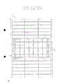
Fig. 1 is the front elevational schematic of the embodiment of the invention.
Fig. 1 (A) is the window frame partial perspective view of the embodiment of the invention.
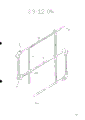
Fig. 2 is a partial perspective view of the embodiment of the invention.
Fig. 3 is that one of the embodiment of the invention is used schematic diagram.
Fig. 4 is a three-dimensional exploded view of embodiment of the invention loose joint bolt seat.
Fig. 5 is the front elevational schematic of another embodiment of the present invention.
Fig. 6 is the partial perspective view of another embodiment of the present invention.
Fig. 7 is the use schematic diagram of another embodiment of the present invention.
At first please consult Fig. 1,2,3 simultaneously, i.e. a front elevational schematic of the embodiment of the invention, partial perspective view and use schematic diagram.
Show that by figure the embodiment of the invention includes the safe window body 1 that can be fixed in wall at least, with and the window 2 reserved of appropriate location, include window frame 3(as for 2 of windows and be roughly concave shaped shown in Fig. 1 (A)) and window bar 4(can partly be hidden in concave shaped window frame 3 inside).
Wherein window bar 4 mainly is to be continuous bending by the long straight-bar body 40 of most roots by loose joint bolt seat 41 successively fixedly to connect to establish and form; And the long straight-bar body of this first long straight-bar body 401 and last root can pass through affixed element 5,6 window frame 3 appropriate locations regularly respectively.In addition; these long straight-bar bodies 40 all can be respectively arranged with the staggered bar 42 with 40 one-tenth vertical configurations of long straight-bar body at the first appropriate intervals place; after the said elements combination; make the safe window body 1 that becomes a complete closure shape; this situation, its function is identical with the Generally Recognized as safe window and have basic antitheft effect and the protection effect of personnel on roof or balcony.
So when meeting and during the danger and disaster situation when fire (such as), then the embodiment of the invention can in time be changed to ladder and uses and have the effect of helping out of distress, and the full peace used of tool, for known safe window or other are restricted body can't be obtained.When chance and danger and disaster, the affixed element 6 that can take off the long straight-bar body of last root easily makes it break away from window frame 3, and unclamp simultaneously after each loose joint bolt seat 41, all long straight-bar body 40 linearly arrangements from top to bottom, so window frame 3 forms an open space 7, personnel can and step on staggered bar 42 successively and flee from a calamity downwards through this open space 7, and an embodiment is enough to confirm that creativity of the present invention, practicality and effect are that the known safe window can not be compared thus.
For taking embodiment of the invention safety assurance in the use into account, and for to make the auditor that more deep understanding can be arranged, special structure and using method with loose joint bolt seat and staggered bar is illustrated.
Please cooperate and consult Fig. 4, be i.e. a three-dimensional exploded view of embodiment of the invention loose joint bolt seat; Showing by figure that the first loose joint bolt seat 41 all includes can utilize affixed element 410(to comprise screw and nut) the two identical bolt lamellar bodies 411 and 412 that engage, and the first bolt lamellar body 411 and 412 all offers a conjugate foramen 4110 and 4120 at appropriate location, and can offer engaging groove 4111 and 412 in the first bolt lamellar body 411 and 412 periphery appropriate locations, can be inserted in inside and strengthen joint (its juncture be mainly be welded on this suit place and make to have the restriction slippage simultaneously and to strengthen conjugation) with convenient long straight-bar body 40; In addition, this every bolt lamellar body 410 and 411 is provided with a clip 4112 and 4122 at peripheral appropriate location again; After two bolt lamellar bodies 410 and 411 utilize affixed element 410 to be a suitable angle (be usually make engaging groove 4111 and 4121 be the best at right angles mutually) joint mutually with the back side (promptly reverse), each long straight-bar body 40 can be continuous bending and fixedly connect and establish (please cooperate and consult Fig. 2).
After unclamping above-mentioned affixed element 410, the present invention is a rotatable wherein bolt lamellar body 411, makes the engaging groove 4111 of this bolt lamellar body 411 linearly with the engaging groove 4121 of another bolt lamellar body 412, and relatedly makes all linearly arrangement of each long straight-bar body 40; And when each long straight-bar body 40 linearly arrangement, two clips 4112 and 4122 are to be the blocking shape mutually, make two bolt lamellar bodies 4112 and the 4122 angle perseverances of rotating mutually can keep a limit value (greatly about about 90 °).And the personnel that can guarantee are unlikely to interlock bolt lamellar body 411 or 412 when in use stepping on staggered bar 42 and produce relative motion or slippages, make personnel's health in the decline process can not produce to shake or rock maybe will shake or rock reduce to minimum, with this safety of strengthening using (please cooperate and consult Fig. 3).
Please look back Fig. 2 more as can be known, it is to form an arciform on-slip body 420 that staggered bar 42 is located endways, personnel are stepped on staggered bar 42 in slow the falling, can utilize on-slip body 420 to prevent the outside slippage of step, strengthen the safety of its use once again and suffice to show that the integrality that the present invention designs.
Please consult Fig. 5,6,7 simultaneously, i.e. the front elevational schematic of another embodiment of the present invention, the partial perspective view of another embodiment and use schematic diagram.
As shown in Figure 5, the permanent position of affixed element 5,6 can be the diagonal angle wire arranges, and in the time of according to this design the embodiment of the invention being used as safe window, a uniform support force can be arranged and is difficult for being partial to single limit.
In addition, per two the adjacent staggered bars 42 that are arranged on the long straight-bar body 40 can be reverse setting, that is the on-slip body 420 of per two adjacent staggered bars 42 can be 180 ° otherness setting, when the embodiment of the invention is launched to use, the mode that staggered bar 42 can be the first from left right side is arranged in order, made things convenient for during use to cooperate moving and stepping in the above of left and right sides pin, have more the effect of balance and safety and be difficult for producing the degree of lacking of skew.
Claims (4)
1, a kind of improvement structure that can doublely do the safety window of ladder use includes the window that safe window body and suitable place thereof are reserved, and then includes window frame and window bar as for window;
It is characterized in that the window bar mainly is to be continuous bending by the long straight-bar body of most roots by loose joint bolt seat successively fixedly to connect to establish and form; And the long straight-bar body of this first long straight-bar body and last root can be fixed in the window frame appropriate location by affixed element respectively; In addition, these long straight-bar bodies all can be respectively arranged with the staggered bar that becomes vertical configuration with long straight-bar body at each appropriate intervals place.
2, according to the described improvement structure that can doublely do the safety window of ladder use of claim 1, it is characterized in that, this each loose joint bolt seat all includes the two identical bolt lamellar bodies that can utilize that affixed element engages, and each bolt lamellar body all offers a conjugate foramen in appropriate location, and can offer an engaging groove in each bolt blade peripheral edge appropriate location and be beneficial to long straight-bar body and can be inserted in inside and strengthen joint; In addition, this each bolt lamellar body is provided with a clip at peripheral appropriate location again; Make after two bolt sheets utilize affixed element to be a suitable angle mutually mutually with the back side to engage, each long straight-bar body can be continuous bending and fixedly connect and establish.
3, the improvement structure that can doublely do the safety window of ladder use according to claim 2 is characterized in that the engaging groove of two bolt lamellar bodies is in the right angle.
4, according to the described improvement structure that can doublely do the safety window of ladder use of claim 1, it is characterized in that staggered bar forms an arciform on-slip body in its end.
Priority Applications (1)
| Application Number | Priority Date | Filing Date | Title |
|---|---|---|---|
| CN 89109012 CN1018564B (en) | 1989-11-30 | 1989-11-30 | Improved structure of safety windows and doors that can also be used as ladder frames |
Applications Claiming Priority (1)
| Application Number | Priority Date | Filing Date | Title |
|---|---|---|---|
| CN 89109012 CN1018564B (en) | 1989-11-30 | 1989-11-30 | Improved structure of safety windows and doors that can also be used as ladder frames |
Publications (2)
| Publication Number | Publication Date |
|---|---|
| CN1052165A CN1052165A (en) | 1991-06-12 |
| CN1018564B true CN1018564B (en) | 1992-10-07 |
Family
ID=4857826
Family Applications (1)
| Application Number | Title | Priority Date | Filing Date |
|---|---|---|---|
| CN 89109012 Expired CN1018564B (en) | 1989-11-30 | 1989-11-30 | Improved structure of safety windows and doors that can also be used as ladder frames |
Country Status (1)
| Country | Link |
|---|---|
| CN (1) | CN1018564B (en) |
-
1989
- 1989-11-30 CN CN 89109012 patent/CN1018564B/en not_active Expired
Also Published As
| Publication number | Publication date |
|---|---|
| CN1052165A (en) | 1991-06-12 |
Similar Documents
| Publication | Publication Date | Title |
|---|---|---|
| CA2020019A1 (en) | Cord lock unit for drape or blind assembly | |
| ES335989A1 (en) | Guardrails such as balcony balustrades | |
| DE2509350C3 (en) | Device for hanging a new suspended ceiling on the supporting structure of an existing suspended ceiling | |
| CN1018564B (en) | Improved structure of safety windows and doors that can also be used as ladder frames | |
| CN2425187Y (en) | Multi-functional collapsible anti-theft grill | |
| DE19619862C2 (en) | Lattice-rung connection, especially in glass facade construction | |
| DE29609930U1 (en) | Telescopic locking rod for securing window sashes against being pressed open from the outside | |
| CN217233332U (en) | Clamp assembly of window structure, window structure and cable net curtain wall | |
| GB2170238A (en) | Connector for connecting a carrier member to an upright member, in particular for forming facade latticeworks | |
| EP2460947B1 (en) | Glazing | |
| DE1299395B (en) | Suspension device for attaching a false ceiling formed from cassettes or the like to a supporting structure | |
| AT513622A4 (en) | Tool-free mounting device for surface elements | |
| CN215369601U (en) | Aluminum alloy horizontal bar for fixing rigid protective net | |
| DE20014310U1 (en) | railing | |
| CN208396625U (en) | A kind of window new type stainless steel. corrosion resistance invisible protective screens | |
| CN2563284Y (en) | Movable safety rail | |
| DE102017000924A1 (en) | plate holder | |
| RU220810U1 (en) | Window protection device | |
| DE3120410A1 (en) | Prefabricated counter-ceiling | |
| DE69700166T2 (en) | Device for attaching hanging alcove separations to a front screen wall | |
| DE3716341A1 (en) | Wood-glass shelving as self-connecting and self-supporting system | |
| CN210178247U (en) | Three-in-one invisible anti-theft net window frame section bar | |
| CN2299143Y (en) | Protective fence | |
| CN209743310U (en) | Stealthy anti-theft net steel wire fixing device | |
| JPH0632123Y2 (en) | Evacuation rope and its hook |
Legal Events
| Date | Code | Title | Description |
|---|---|---|---|
| C10 | Entry into substantive examination | ||
| SE01 | Entry into force of request for substantive examination | ||
| C06 | Publication | ||
| PB01 | Publication | ||
| C13 | Decision | ||
| GR02 | Examined patent application | ||
| C14 | Grant of patent or utility model | ||
| GR01 | Patent grant | ||
| C19 | Lapse of patent right due to non-payment of the annual fee | ||
| CF01 | Termination of patent right due to non-payment of annual fee |