CN101854867B - Closure device, deployment apparatus, and method of deploying a closure device - Google Patents
Closure device, deployment apparatus, and method of deploying a closure device Download PDFInfo
- Publication number
- CN101854867B CN101854867B CN2008801155939A CN200880115593A CN101854867B CN 101854867 B CN101854867 B CN 101854867B CN 2008801155939 A CN2008801155939 A CN 2008801155939A CN 200880115593 A CN200880115593 A CN 200880115593A CN 101854867 B CN101854867 B CN 101854867B
- Authority
- CN
- China
- Prior art keywords
- closing device
- pedal plate
- wire rod
- stopper
- expanding unit
- Prior art date
- Legal status (The legal status is an assumption and is not a legal conclusion. Google has not performed a legal analysis and makes no representation as to the accuracy of the status listed.)
- Expired - Fee Related
Links
- 238000000034 method Methods 0.000 title abstract description 26
- 229910052751 metal Inorganic materials 0.000 claims description 27
- 239000002184 metal Substances 0.000 claims description 27
- 238000005452 bending Methods 0.000 claims description 23
- 229910000861 Mg alloy Inorganic materials 0.000 claims description 14
- 239000004033 plastic Substances 0.000 claims description 13
- 229920003023 plastic Polymers 0.000 claims description 13
- FYYHWMGAXLPEAU-UHFFFAOYSA-N Magnesium Chemical compound [Mg] FYYHWMGAXLPEAU-UHFFFAOYSA-N 0.000 claims description 6
- 230000015572 biosynthetic process Effects 0.000 claims description 6
- 229910052749 magnesium Inorganic materials 0.000 claims description 6
- 239000011777 magnesium Substances 0.000 claims description 6
- 238000006065 biodegradation reaction Methods 0.000 claims description 4
- 210000004204 blood vessel Anatomy 0.000 abstract description 84
- 238000007789 sealing Methods 0.000 abstract description 15
- 230000000740 bleeding effect Effects 0.000 abstract description 7
- 239000013060 biological fluid Substances 0.000 abstract description 6
- 210000000056 organ Anatomy 0.000 abstract description 6
- 238000001125 extrusion Methods 0.000 description 47
- 230000007246 mechanism Effects 0.000 description 33
- 210000001519 tissue Anatomy 0.000 description 30
- 210000003141 lower extremity Anatomy 0.000 description 28
- 230000009471 action Effects 0.000 description 23
- 230000003321 amplification Effects 0.000 description 21
- 238000003199 nucleic acid amplification method Methods 0.000 description 21
- 241000282472 Canis lupus familiaris Species 0.000 description 18
- 238000005516 engineering process Methods 0.000 description 16
- 239000008280 blood Substances 0.000 description 13
- 210000004369 blood Anatomy 0.000 description 13
- 230000008878 coupling Effects 0.000 description 13
- 238000010168 coupling process Methods 0.000 description 13
- 238000005859 coupling reaction Methods 0.000 description 13
- 238000010008 shearing Methods 0.000 description 13
- 229920000642 polymer Polymers 0.000 description 12
- 238000005520 cutting process Methods 0.000 description 8
- 210000002414 leg Anatomy 0.000 description 8
- 238000003466 welding Methods 0.000 description 8
- 208000032843 Hemorrhage Diseases 0.000 description 7
- 230000008901 benefit Effects 0.000 description 7
- 238000004519 manufacturing process Methods 0.000 description 7
- 208000034158 bleeding Diseases 0.000 description 6
- 230000017531 blood circulation Effects 0.000 description 6
- 230000006698 induction Effects 0.000 description 5
- 230000000149 penetrating effect Effects 0.000 description 5
- 238000013016 damping Methods 0.000 description 4
- 238000006073 displacement reaction Methods 0.000 description 4
- 210000001105 femoral artery Anatomy 0.000 description 4
- 238000005242 forging Methods 0.000 description 4
- 230000006870 function Effects 0.000 description 4
- 238000003754 machining Methods 0.000 description 4
- 239000000463 material Substances 0.000 description 4
- 238000012545 processing Methods 0.000 description 4
- 206010018852 Haematoma Diseases 0.000 description 3
- 206010053648 Vascular occlusion Diseases 0.000 description 3
- 238000000429 assembly Methods 0.000 description 3
- 230000000712 assembly Effects 0.000 description 3
- 238000005266 casting Methods 0.000 description 3
- 230000000694 effects Effects 0.000 description 3
- 238000001727 in vivo Methods 0.000 description 3
- 230000002427 irreversible effect Effects 0.000 description 3
- 230000004048 modification Effects 0.000 description 3
- 238000012986 modification Methods 0.000 description 3
- 238000000465 moulding Methods 0.000 description 3
- 238000011017 operating method Methods 0.000 description 3
- 238000012856 packing Methods 0.000 description 3
- 206010033675 panniculitis Diseases 0.000 description 3
- 230000008569 process Effects 0.000 description 3
- 238000004080 punching Methods 0.000 description 3
- 229910052761 rare earth metal Inorganic materials 0.000 description 3
- 150000002910 rare earth metals Chemical class 0.000 description 3
- 238000004513 sizing Methods 0.000 description 3
- 210000004304 subcutaneous tissue Anatomy 0.000 description 3
- 238000001356 surgical procedure Methods 0.000 description 3
- 229920001169 thermoplastic Polymers 0.000 description 3
- 239000004416 thermosoftening plastic Substances 0.000 description 3
- 230000002792 vascular Effects 0.000 description 3
- 208000021331 vascular occlusion disease Diseases 0.000 description 3
- 229920000954 Polyglycolide Polymers 0.000 description 2
- 210000001367 artery Anatomy 0.000 description 2
- 230000008859 change Effects 0.000 description 2
- 238000007887 coronary angioplasty Methods 0.000 description 2
- 238000010438 heat treatment Methods 0.000 description 2
- 239000007943 implant Substances 0.000 description 2
- 238000002513 implantation Methods 0.000 description 2
- 238000003780 insertion Methods 0.000 description 2
- 230000037431 insertion Effects 0.000 description 2
- 238000002372 labelling Methods 0.000 description 2
- 239000002906 medical waste Substances 0.000 description 2
- 229920001432 poly(L-lactide) Polymers 0.000 description 2
- 239000004633 polyglycolic acid Substances 0.000 description 2
- 230000000717 retained effect Effects 0.000 description 2
- 238000003892 spreading Methods 0.000 description 2
- 230000007480 spreading Effects 0.000 description 2
- 230000003068 static effect Effects 0.000 description 2
- 241000567030 Ampulloclitocybe clavipes Species 0.000 description 1
- 206010003226 Arteriovenous fistula Diseases 0.000 description 1
- 229910052684 Cerium Inorganic materials 0.000 description 1
- 229910052692 Dysprosium Inorganic materials 0.000 description 1
- 229910052691 Erbium Inorganic materials 0.000 description 1
- 229910052693 Europium Inorganic materials 0.000 description 1
- 208000009087 False Aneurysm Diseases 0.000 description 1
- 206010016717 Fistula Diseases 0.000 description 1
- 229910052688 Gadolinium Inorganic materials 0.000 description 1
- 229910052689 Holmium Inorganic materials 0.000 description 1
- 229910052779 Neodymium Inorganic materials 0.000 description 1
- 208000002193 Pain Diseases 0.000 description 1
- 206010033799 Paralysis Diseases 0.000 description 1
- 229910052777 Praseodymium Inorganic materials 0.000 description 1
- 229910052773 Promethium Inorganic materials 0.000 description 1
- 206010058360 Retroperitoneal haematoma Diseases 0.000 description 1
- 229910052772 Samarium Inorganic materials 0.000 description 1
- 206010040026 Sensory disturbance Diseases 0.000 description 1
- 206010043101 Talipes Diseases 0.000 description 1
- 229910052771 Terbium Inorganic materials 0.000 description 1
- 229910052775 Thulium Inorganic materials 0.000 description 1
- 206010048975 Vascular pseudoaneurysm Diseases 0.000 description 1
- 229910052769 Ytterbium Inorganic materials 0.000 description 1
- 229910045601 alloy Inorganic materials 0.000 description 1
- 239000000956 alloy Substances 0.000 description 1
- 210000003484 anatomy Anatomy 0.000 description 1
- 210000001217 buttock Anatomy 0.000 description 1
- GWXLDORMOJMVQZ-UHFFFAOYSA-N cerium Chemical compound [Ce] GWXLDORMOJMVQZ-UHFFFAOYSA-N 0.000 description 1
- 201000011228 clubfoot Diseases 0.000 description 1
- 238000010276 construction Methods 0.000 description 1
- 238000001816 cooling Methods 0.000 description 1
- 238000002788 crimping Methods 0.000 description 1
- 238000002224 dissection Methods 0.000 description 1
- KBQHZAAAGSGFKK-UHFFFAOYSA-N dysprosium atom Chemical compound [Dy] KBQHZAAAGSGFKK-UHFFFAOYSA-N 0.000 description 1
- 238000010894 electron beam technology Methods 0.000 description 1
- UYAHIZSMUZPPFV-UHFFFAOYSA-N erbium Chemical compound [Er] UYAHIZSMUZPPFV-UHFFFAOYSA-N 0.000 description 1
- OGPBJKLSAFTDLK-UHFFFAOYSA-N europium atom Chemical compound [Eu] OGPBJKLSAFTDLK-UHFFFAOYSA-N 0.000 description 1
- 238000002474 experimental method Methods 0.000 description 1
- 230000003890 fistula Effects 0.000 description 1
- UIWYJDYFSGRHKR-UHFFFAOYSA-N gadolinium atom Chemical compound [Gd] UIWYJDYFSGRHKR-UHFFFAOYSA-N 0.000 description 1
- 230000023597 hemostasis Effects 0.000 description 1
- KJZYNXUDTRRSPN-UHFFFAOYSA-N holmium atom Chemical compound [Ho] KJZYNXUDTRRSPN-UHFFFAOYSA-N 0.000 description 1
- 238000009434 installation Methods 0.000 description 1
- 229910052746 lanthanum Inorganic materials 0.000 description 1
- FZLIPJUXYLNCLC-UHFFFAOYSA-N lanthanum atom Chemical compound [La] FZLIPJUXYLNCLC-UHFFFAOYSA-N 0.000 description 1
- OHSVLFRHMCKCQY-UHFFFAOYSA-N lutetium atom Chemical compound [Lu] OHSVLFRHMCKCQY-UHFFFAOYSA-N 0.000 description 1
- 230000007721 medicinal effect Effects 0.000 description 1
- 210000004115 mitral valve Anatomy 0.000 description 1
- 239000000203 mixture Substances 0.000 description 1
- 210000003205 muscle Anatomy 0.000 description 1
- QEFYFXOXNSNQGX-UHFFFAOYSA-N neodymium atom Chemical compound [Nd] QEFYFXOXNSNQGX-UHFFFAOYSA-N 0.000 description 1
- 210000005036 nerve Anatomy 0.000 description 1
- 230000035479 physiological effects, processes and functions Effects 0.000 description 1
- 229920001606 poly(lactic acid-co-glycolic acid) Polymers 0.000 description 1
- 239000011148 porous material Substances 0.000 description 1
- PUDIUYLPXJFUGB-UHFFFAOYSA-N praseodymium atom Chemical compound [Pr] PUDIUYLPXJFUGB-UHFFFAOYSA-N 0.000 description 1
- 230000002265 prevention Effects 0.000 description 1
- VQMWBBYLQSCNPO-UHFFFAOYSA-N promethium atom Chemical compound [Pm] VQMWBBYLQSCNPO-UHFFFAOYSA-N 0.000 description 1
- 230000002040 relaxant effect Effects 0.000 description 1
- 230000008439 repair process Effects 0.000 description 1
- KZUNJOHGWZRPMI-UHFFFAOYSA-N samarium atom Chemical compound [Sm] KZUNJOHGWZRPMI-UHFFFAOYSA-N 0.000 description 1
- 229910052706 scandium Inorganic materials 0.000 description 1
- SIXSYDAISGFNSX-UHFFFAOYSA-N scandium atom Chemical compound [Sc] SIXSYDAISGFNSX-UHFFFAOYSA-N 0.000 description 1
- 230000035807 sensation Effects 0.000 description 1
- 238000000926 separation method Methods 0.000 description 1
- 239000007787 solid Substances 0.000 description 1
- GZCRRIHWUXGPOV-UHFFFAOYSA-N terbium atom Chemical compound [Tb] GZCRRIHWUXGPOV-UHFFFAOYSA-N 0.000 description 1
- 238000002560 therapeutic procedure Methods 0.000 description 1
- 230000007306 turnover Effects 0.000 description 1
- 210000003462 vein Anatomy 0.000 description 1
- NAWDYIZEMPQZHO-UHFFFAOYSA-N ytterbium Chemical compound [Yb] NAWDYIZEMPQZHO-UHFFFAOYSA-N 0.000 description 1
Images


Classifications
-
- A—HUMAN NECESSITIES
- A61—MEDICAL OR VETERINARY SCIENCE; HYGIENE
- A61B—DIAGNOSIS; SURGERY; IDENTIFICATION
- A61B17/00—Surgical instruments, devices or methods, e.g. tourniquets
- A61B17/0057—Implements for plugging an opening in the wall of a hollow or tubular organ, e.g. for sealing a vessel puncture or closing a cardiac septal defect
-
- A—HUMAN NECESSITIES
- A61—MEDICAL OR VETERINARY SCIENCE; HYGIENE
- A61B—DIAGNOSIS; SURGERY; IDENTIFICATION
- A61B17/00—Surgical instruments, devices or methods, e.g. tourniquets
- A61B2017/00004—(bio)absorbable, (bio)resorbable, resorptive
-
- A—HUMAN NECESSITIES
- A61—MEDICAL OR VETERINARY SCIENCE; HYGIENE
- A61B—DIAGNOSIS; SURGERY; IDENTIFICATION
- A61B17/00—Surgical instruments, devices or methods, e.g. tourniquets
- A61B2017/00367—Details of actuation of instruments, e.g. relations between pushing buttons, or the like, and activation of the tool, working tip, or the like
-
- A—HUMAN NECESSITIES
- A61—MEDICAL OR VETERINARY SCIENCE; HYGIENE
- A61B—DIAGNOSIS; SURGERY; IDENTIFICATION
- A61B17/00—Surgical instruments, devices or methods, e.g. tourniquets
- A61B17/0057—Implements for plugging an opening in the wall of a hollow or tubular organ, e.g. for sealing a vessel puncture or closing a cardiac septal defect
- A61B2017/00575—Implements for plugging an opening in the wall of a hollow or tubular organ, e.g. for sealing a vessel puncture or closing a cardiac septal defect for closure at remote site, e.g. closing atrial septum defects
- A61B2017/00623—Introducing or retrieving devices therefor
-
- A—HUMAN NECESSITIES
- A61—MEDICAL OR VETERINARY SCIENCE; HYGIENE
- A61B—DIAGNOSIS; SURGERY; IDENTIFICATION
- A61B17/00—Surgical instruments, devices or methods, e.g. tourniquets
- A61B17/0057—Implements for plugging an opening in the wall of a hollow or tubular organ, e.g. for sealing a vessel puncture or closing a cardiac septal defect
- A61B2017/00637—Implements for plugging an opening in the wall of a hollow or tubular organ, e.g. for sealing a vessel puncture or closing a cardiac septal defect for sealing trocar wounds through abdominal wall
-
- A—HUMAN NECESSITIES
- A61—MEDICAL OR VETERINARY SCIENCE; HYGIENE
- A61B—DIAGNOSIS; SURGERY; IDENTIFICATION
- A61B17/00—Surgical instruments, devices or methods, e.g. tourniquets
- A61B17/0057—Implements for plugging an opening in the wall of a hollow or tubular organ, e.g. for sealing a vessel puncture or closing a cardiac septal defect
- A61B2017/00641—Implements for plugging an opening in the wall of a hollow or tubular organ, e.g. for sealing a vessel puncture or closing a cardiac septal defect for closing fistulae, e.g. anorectal fistulae
-
- A—HUMAN NECESSITIES
- A61—MEDICAL OR VETERINARY SCIENCE; HYGIENE
- A61B—DIAGNOSIS; SURGERY; IDENTIFICATION
- A61B17/00—Surgical instruments, devices or methods, e.g. tourniquets
- A61B17/0057—Implements for plugging an opening in the wall of a hollow or tubular organ, e.g. for sealing a vessel puncture or closing a cardiac septal defect
- A61B2017/00646—Type of implements
- A61B2017/00654—Type of implements entirely comprised between the two sides of the opening
-
- A—HUMAN NECESSITIES
- A61—MEDICAL OR VETERINARY SCIENCE; HYGIENE
- A61B—DIAGNOSIS; SURGERY; IDENTIFICATION
- A61B17/00—Surgical instruments, devices or methods, e.g. tourniquets
- A61B17/0057—Implements for plugging an opening in the wall of a hollow or tubular organ, e.g. for sealing a vessel puncture or closing a cardiac septal defect
- A61B2017/00646—Type of implements
- A61B2017/00659—Type of implements located only on one side of the opening
-
- A—HUMAN NECESSITIES
- A61—MEDICAL OR VETERINARY SCIENCE; HYGIENE
- A61B—DIAGNOSIS; SURGERY; IDENTIFICATION
- A61B17/00—Surgical instruments, devices or methods, e.g. tourniquets
- A61B17/0057—Implements for plugging an opening in the wall of a hollow or tubular organ, e.g. for sealing a vessel puncture or closing a cardiac septal defect
- A61B2017/00672—Locating means therefor, e.g. bleed back lumen
Abstract
The present invention relates generally to medical devices and methods for sealing and closing passages formed through tissue. More specifically, the present invention relates to devices for sealing or closing an opening formed through biological tissue comprising a distal or outside margin or surface, and a proximal or inside margin or surface (i.e., a wall thickness), and to apparatuses and methods for delivering such devices, to control (or prevent or stop) bleeding (or the flow of other biological fluid or tissue). The openings comprise percutaneously formed punctures, incisions, or other openings formed through biological tissue, such as in blood vessels, organs, and the like.
Description
Related application data
The application based on and require the priority of U.S. Provisional Patent Application that JIUYUE in 2007 submits on the 12nd number 60/971,618, its full content is incorporated to this paper by reference.
Technical field
The present invention relates generally to medical apparatus and instruments and the method for shutoff and the closed passage formed through tissue.More specifically, the present invention relates to the device of the opening that forms for biological tissue's (being wall thickness) on shutoff or closed edge through comprising distally or the outside or surface and nearside or inboard edge or surface, and relate to for sending above-mentioned this device and bleeding to control (or prevent or stop) apparatus and method of (or other biological fluid or tissue flow).Described opening comprises point of puncture, otch or other openings that form through biological tissues such as blood vessel or organ.
Background technology
For for the endovascular surgical operations such as Heart catheterization and intervene operations such as percutaneous tranluminal coronary angioplasty or support, entering tremulous pulse or vein blood vessel system.Usually, by hollow needle is inserted in vascular system (for example,, such as tremulous pulsies such as femoral artery) and carries out these endovascular surgical operations through patient's skin (percutaneously) and any stroma.Then can make seal wire pass the pin inner chamber and enter patient's blood vessel.Once seal wire is in place, just can removes pin and seal wire is stayed to this place.Lead sheath for example can or follow dilator together with dilator closely and crosses seal wire afterwards and advance in blood vessel.Then, use the conduit of percutaneous opening or other devices to cross seal wire and to advance to endovascular desired locations through the inner chamber of lead sheath.
When completing endovascular operation, can remove conduit, lead sheath, seal wire and other medical apparatus and instruments parts, stay the opening (so-called site of puncture or arteriotomy) that can make blood flow to outside (bleeding) in blood vessel wall and proximal tissue organ.Can apply to the site of puncture of percutaneous external pressure (artificial compressing) until hemopexis and wound sealing.Yet this operation is expensive and time-consuming, need doctor or nurse to reach the time of one hour.And the patient is also uncomfortable, and require the patient to keep motionless in operating room, conduit insertion control laboratory Huo Liuzhi district.In addition, existed the danger of hematoma occurs owing to bleeding before realizing hemostasis.
When stopping bleeding, often elastic bandage (pressure bandage) or sandbag are placed on site of puncture; This will exert pressure in case the grumeleuse that stops blooding is washed away by endovascular pressure, and above-mentioned this situation easily occurs, especially in the situation that arterypuncture.This pressure bandage or sandbag must keep certain hour at this place, and clinical is not waited from 8 hours by 24 hours.At pressure bandage, in time period in place, the patient must keep lying up.After removing pressure bandage, the patient can reactivate.In fact, this often means that patient after the cutaneous artery operation and must stay for a long time hospital, often will spend the night in hospital.
This external pressure treatment (artificial compressing) is associated with many complication intrinsic in technology.Except may occurring acutely bleeding, also may cause false aneurysm (thus at the inner chamber of blood vessel and be positioned between circumvascular grumeleuse (hematoma) have passage via site of puncture), arteriovenous fistula (Arterial system of blood vessel and the passage between Venous system) and retroperitoneal hematoma.Contiguous nerve also may be squeezed or sustain damage due to directly pressure or massive hemorrhage, thereby causes pain, sensory disturbance or paralysed by these innerv muscle groups.The ratio that occurs these complication in all operations accounts for greatly 1%-3%.Sometimes need the surgery interventional therapy, alleviate thus hematoma and sew up site of puncture (if necessary, but any fistula of shutoff).
Multiple device and apparatus have been proposed, these devices and apparatus are used for edge (limit) by sealing or joint site of puncture and carry out percutaneously shutoff vascular puncture point (those skilled in the art should known these devices and apparatus, do not need all to be specifically introduced) here.These devices and apparatus relate to must be via launching the artificial closing device launched of instrument.Such as the U.S. Patent No. 5,676,689 referring to issues such as Kensey.About prior art, the effect of vessel sealing depends on the ability that the user accurately positions closing device with respect to site of puncture with groping when being performed the operation to a great extent.The artificial expansion means of this vascular occlusion device (step and the device that carry out with a plurality of users are operating as feature) impel the subjectivity that User Exploitation is high " sensation " or " haptic technology " so that reliable and correctly positioning closing device.
The operating procedure of the many users' inductions of this and (prior-art devices), use the requirement of the mutually related sense of touch operation of difficulty, Term Learning curve and low precision to cause the application rate of vascular occlusion device in the middle of the Heart catheterization experiment slow.As a result, infringement is to patient's interests (comfortable and medical effect improves) with to the interests (treating capacity improves and cost) of mechanism.
Summary of the invention
Therefore, main purpose of the present invention is to provide and compares expanding unit or the instrument (for launching closed implant) with following high ease for use with existing apparatus (as discussed above) with advantage, that is: the operating procedure of user's induction of (1) minimized sense of touch operation, (2) minimum, the user learning of (3) minimum how to use efficiently practice periods, (4) of expanding unit or instrument to improve closed precision and (5) improve the expectation that typical user is used this expanding unit or instrument.More specifically, main purpose of the present invention and advantage are to provide expanding unit or the instrument with automatic function.
Another object of the present invention is to provide with first generation closing device as above and compares the closing device that better more effective seal can repeatedly be provided with advantage.
Further purpose of the present invention and advantage are to provide a kind of like this closing device, and it dissolves (biodegradation) in vivo, allow tremulous pulse in the future current, i.e. " again bonding ".
Another object of the present invention and advantage are to provide a kind of like this closing device, it can be operable to and be locked in appropriate location and be implanted into (described closing device) to stablize the closure of crossing blood vessel wall, implant structure extruding blood vessel wall, then remain on this place (locking) and irremovable.One of risk of bleeding in existing apparatus is that these existing apparatus can not provide the closed structure of resisting the movement caused due to physiology action (buttocks bending etc.).Therefore, allow safer the walking about in early days of patient according to locking (stablizing) device of the embodiment of the present invention.
According to aforementioned purpose and advantage, embodiments of the invention provide medical apparatus and instruments and the method for shutoff and the closed passage formed through tissue that overcomes the problems of the prior art.More specifically, the device of the opening formed for biological tissue's (being wall thickness) on shutoff or closed edge through comprising distally or the outside or surface and nearside or inboard edge or surface is provided, and provides for sending above-mentioned this device and bleed to control (or prevent or stop) apparatus and method of (or other biological fluid or tissue flow).Described opening comprises point of puncture, otch or other openings that form through biological tissues such as blood vessel or organ.
According to embodiments of the invention, a kind of like this closing device is provided, its opening formed through the biological tissue of various sizes for shutoff (for example,, due to the opening formed such as diagnostic conduit insertion or the small-sized percutaneous puncture operation such as coronary angioplasty or Stent and due to the opening of such as large-scale percutaneous punctures such as mitral valve repair technology, performing the operation and forming).
According to embodiments of the invention, a kind of closing device of the opening formed through biological tissue for shutoff is provided, and it comprises pedal plate (footplate), stopper and the wire rod that launches configuration position (closing device launches configuration before launching) before closing device launches.
According to embodiments of the invention, a kind of closing device of the opening formed through biological tissue for shutoff is provided, it comprises pedal plate, stopper and the wire rod that launches the configuration position after closing device launches.
According to embodiments of the invention, described pedal plate comprises overall structure, is fabricated to the single structure (linear) of the distal portions that comprises wire rod.The distal portions that comprises the wire rod of pedal plate comprises annular or the oval-shaped distal portions of wire rod.The embodiment of the integral body of described pedal plate can be operable to the generation plastic deformation.
According to embodiments of the invention, described pedal plate comprises and is independent of described wire rod and is permanently attached to the structure on described wire rod.Pedal plate partly comprises the board of punching press or machining.In the present embodiment, wire rod preferably can be soldered on pedal plate for the part of distal portions.This welding embodiment of pedal plate can be operable to the generation plastic deformation.As another kind, select, wire rod preferably for the part of distal portions is installed on pedal plate by ball-bracket mechanism/structure, or hingedly be installed on pedal plate by linkage.
According to embodiments of the invention, pedal plate is independent of wire rod, and can hingedly be installed on wire rod, such as above-mentioned ball-bracket mechanism.
According to embodiments of the invention, wire rod is installed on pedal plate by ball-bracket structure, and described ball and wire rod are integrated and coaxial with wire rod thus, and the diameter of described ball (spheroid) is greater than the diameter of wire rod thus.In addition, the far-end of described ball and wire rod is positioned at same position thus.Described ball can be by (making the balling-up of material wire melt flow or spheroid form such as fusing, then make this ball cooling and curing) etc. method be formed on the far-end of wire rod, wherein, heating source can be for example laser or induction type heater or other heating source.As another kind, select, spheric end can be spherical part (such as the solid sphere with through hole) independently, and it can allow that by means of crimping, rotation swaged forging, laser weld or other means such as means are installed to the far-end of wire rod.
According to embodiments of the invention, pedal plate and wire rod (comprising the independent spherical part as pommel) comprise biocompatible biological corrodible metal.
According to embodiments of the invention, pedal plate and wire rod (comprising the independent spherical pommel) comprise biocompatible biological corrodible metal, and this biocompatible biological corrodible metal comprises magnesium.
According to embodiments of the invention, pedal plate and wire rod (comprising the independent spherical pommel) comprise biocompatible biological corrodible metal, this biocompatible biological corrodible metal comprises that magnesium alloy (for example, Mg9980A, Mg9990A, Mg9995A, AM100A, AZ63A, AZ91A, AZ91B, AZ91C, AZ92A, AZ81A, EK30A, EK41A, EZ33A, HK31A, HZ32A, K1A, ZE41A, ZH62A, ZK51A, ZK61A, AZ31B, AZ31C, AZ61A, AZ80A, HM31A, M1A, ZK21A, ZK60A, (P) ZK60B, HM21A, ZE10A, TA54A, WE54, WE43, ZW3, AZM, AZ80, AZ31, ZM21, ZK60 etc.).
According to embodiments of the invention, pedal plate and wire rod (comprising the independent spherical pommel) comprise biocompatible biological corrodible metal, and this biocompatible biological corrodible metal comprises the magnesium alloy of magnesium and rare earth metal.
According to embodiments of the invention, pedal plate and wire rod (comprising the independent spherical pommel) comprise biocompatible biological corrodible metal, this biocompatible biological corrodible metal comprises the magnesium alloy of magnesium and at least one rare earth metal, wherein selects inter alia described at least one rare earth metal from the group be comprised of scandium, lanthanum, cerium, praseodymium, neodymium, promethium, samarium, europium, gadolinium, terbium, dysprosium, holmium, erbium, thulium, ytterbium and lutecium.
According to embodiments of the invention, pedal plate comprises biologically absorbable polymer, and wire rod (comprising the independent spherical pommel) comprises biocompatible biological corrodible metal, and described biocompatible biological corrodible metal comprises the biocompatible biological corrodible metal of above-mentioned discussion.
According to embodiments of the invention, pedal plate comprises that biologically absorbable polymer (for example, Poly-L-lactide (PLLA), polylactic acid-Co-glycolic (PLGA) and polyglycolic acid (PGA) etc.), and wire rod can comprise as above disclosed biocompatible biological corrodible metal.
According to embodiments of the invention, pedal plate can comprise biocompatible biological corrodible metal, and wire rod can comprise biologically absorbable polymer, wherein said biologically absorbable polymer comprises as above disclosed biocompatible biological corrodible metal, and described biologically absorbable polymer comprises as above disclosed biologically absorbable polymer.
Can manufacture by multiple manufacturing technology the embodiment of pedal plate.These technology inter alia as required or expectation comprises that effectively molded, extruding, machining, punching press, casting, forging, cut and/or processing, laminat molding, bonding are fixed, the combination of welding and above-mentioned technology, but are not limited to cited technology.
According to embodiments of the invention, wire rod comprises stretching element.
According to embodiments of the invention, wire rod comprises stretching element, and wherein said stretching element comprises many fibrils.
According to embodiments of the invention, wire rod comprises stretching element, and wherein said stretching element comprises many fibrils, and wherein said many fibrils comprise many fibrils knitted parts.
According to embodiments of the invention, wire rod comprises stretching element, and wherein said stretching element comprises monofilament.
According to embodiments of the invention, pedal plate and wire rod all can comprise biologically absorbable polymer, and described biologically absorbable polymer comprises as above disclosed biologically absorbable polymer.
According to embodiments of the invention, stopper comprises biologically absorbable polymer, and described biologically absorbable polymer comprises as above disclosed biologically absorbable polymer.
According to embodiments of the invention, stopper comprises biocompatible biological corrodible metal, and described biocompatible biological corrodible metal comprises as above disclosed biocompatible biological corrodible metal.
According to embodiments of the invention, stopper is for taper shape and comprise distal portions and proximal part, and wherein the diameter of the distal portions of stopper is less than the diameter of the proximal part of stopper.
Can manufacture by multiple manufacturing technology the embodiment of stopper.These technology inter alia as required or expectation comprises that effectively molded, extruding, machining, deep draw, casting, forging, cut and/or processing, laminat molding, bonding are fixed, the combination of welding and above-mentioned technology, but are not limited to cited technology.
According to embodiments of the invention, closing device is biodegradable.
According to embodiments of the invention, pedal plate forms with the speed faster than stopper biodegradation in vivo, makes the first complete biodegradable of pedal plate before the stopper complete biodegradable.
According to embodiments of the invention, a kind of like this expanding unit or instrument are provided, it is easy to use, the needs of sense of touch operation are minimized, provide the user of minimum to respond to operating procedure, need user's practice periods of minimum learn how effectively to use described expanding unit or instrument (" short learning curve ") and have high accuracy, and all these will cause improving the expectation that typical user is used this expanding unit or instrument.More specifically, according to embodiments of the invention, provide a kind of expanding unit or instrument with automatic function of the closing device that launches the embodiment of the present invention.
According to embodiments of the invention, a kind of like this expanding unit or instrument are provided, it (for example uses housing, at least one first pushing or elastomeric element, miscellaneous part or the mechanism of kinetic energy can be stored and discharge to wind spring, leaf spring, constant force spring maybe), first removable/slidably element and the first relieving mechanism (for example, pin releasing device, hook-shoulder releasing device, cam wheel releasing device, collar releasing device or can under spring load, discharge other mechanisms of an assembly or a plurality of assemblies).
According to embodiments of the invention, a kind of like this expanding unit or instrument are provided, it (for example uses housing, at least one second pushing or spring members, miscellaneous part or the mechanism of kinetic energy can be stored and discharge to wind spring, leaf spring, constant force spring maybe), second removable/slidably element and the second relieving mechanism (for example, pin releasing device, hook-shoulder releasing device, collar releasing device or can under spring load, discharge other mechanisms of an assembly or a plurality of assemblies).
According to embodiments of the invention, a kind of expanding unit or instrument of mainly being manufactured by the thermoplastic part is provided, it can be abandoned immediately after the vascular occlusion device that launches the embodiment of the present invention.The expanding unit of the main embodiment of the present invention by the manufacture of thermoplastic part can provide the airtight cost-efficient means (via cheap material) that are formed on the opening in biological tissue.
According to embodiments of the invention, a kind of opening formed through biological tissue for shutoff (puncture formed such as percutaneous is provided, comprise the opening be formed on blood vessel wall) system of bleed to control (or prevent or stop) (or other biological fluid or tissue flow), described system comprises for the closing device of this opening of shutoff with for closing device being deployed into to the expanding unit of opening with the shutoff opening.The puncture that percutaneous forms also comprises the anatomic passages of bordering on the opening be formed on blood vessel wall, and this anatomic passages extends and arrives the surface that is stacked and placed on the skin on blood vessel through tissue.As mentioned above, described closing device comprises stopper, wire rod and pedal plate.Described expanding unit comprises: comprise distally, outside C shape pipe and be contained in the distally C shape pipe that this distally, outside C shape is managed interior inboard distally C shape pipe, skin flange assembly (its part is coaxial with the longitudinal axis of wire rod), the shell sheath, control housing, the nearside pipe that comprises outside nearside pipe and inboard nearside pipe, ejector sleeve, the sliding cylinder assembly that comprises sliding cylinder and cut-out lever, the push part that comprises a plurality of horizontal constant force springs, the second push part that comprises constant force spring and lower constant force spring, the wire ferrule (wherein this U-shaped structure comprises the near-end of sealing and unlimited far-end) and the extrusion lever Handleset that comprise long U-shaped structure, this extrusion lever Handleset comprises extrusion lever hands handle, remain on interior button and the connecting rod of guard ring part of extrusion lever handle, wherein button can slide in the guard ring part.
According to embodiments of the invention, before launching, closing device launches the configuration position, and pedal plate is positioned at the far-end of distally, outside C shape pipe.The near-end of pedal plate is against the far-end of inboard distally C shape pipe.Stopper is positioned at the nearside of pedal plate, and is positioned at the distal portions of outside nearside pipe and is adjacent to ejector sleeve in distally along the longitudinal axis of wire rod.Wire rod extends through inboard distally C shape pipe from the near-end of pedal plate towards nearside, through the axial hole stopper and through ejector sleeve, and be installed on the inboard part of closed proximal end of wire ferrule.
According to embodiments of the invention, two distally C shape pipes nest together with one heart and form through main pipe zone wherein.The main pipe zone can be operable to as the blood mark channel.Outside distally C shape pipe and inboard distally C shape are managed and are comprised respectively that side opening, two side holes are aimed at concentrically with respect to one another and can be operable to and flow through the gas outlet of blood mark channel as blood from blood vessel towards nearside.Distally, outside C shape pipe comprises the ingate near the far-end of distally, outside C shape pipe.This ingate as enter the inlet port of blood mark channel and preferably near the closing device of the near-end of pedal plate, launch before expanded position.This allows the whole pedal plate of indication in blood vessel.Pressure because the pressure at place, gas outlet is located lower than ingate, cause blood to flow through the blood mark channel towards nearside.
According to embodiments of the invention, the main pipe zone can be operable to as the spreading area that launches stopper.Distally C shape pipe can be operable to expansion partly and separate, and causes irreversible not nested state, the configuration position after the intravasation expansion to allow stopper therefrom to pass, and wherein the proximal diameter of stopper is greater than the internal diameter in main pipe zone.
According to embodiments of the invention, distally C shape pipe can be operable to the longitudinal axis coaxial slip independently with wire rod.
According to embodiments of the invention, expanding unit also comprises guidewire lumen, and this guidewire lumen comprises proximal guidewire outlet and for inserting the distal guide entrance of seal wire.When inserting seal wire, seal wire extends through the point of puncture of percutaneous formation and arrives the distal guide entrance towards the proximal direction percutaneous from the inner chamber of blood vessel.Seal wire extends through guidewire lumen from the distal guide entrance towards nearside and arrives the proximal guidewire outlet, and wherein seal wire exits from guidewire lumen towards nearside.
According to embodiments of the invention, the skin flange assembly comprises far-end and near-end, and can be operable to along the longitudinal axis of controlling housing and slide towards distally.Portions of proximal is slided along the Outboard Sections of controlling housing, and distal part is slided along the Outboard Sections of distally C shape pipe.
According to embodiments of the invention, control the housing part and held by the skin flange assembly.
According to embodiments of the invention, the nearside pipe is contained in to control in housing and can be operable to along the longitudinal axis of wire rod and slides independently.
According to embodiments of the invention, sliding cylinder is installed to the distally of the position on the wire ferrule of controlling in housing substantially at the proximal part of wire rod.The sliding cylinder assembly can be operable to along the longitudinal axis of wire rod and slide towards distally.
According to embodiments of the invention, ejector sleeve can be operable to stopper is pushed into after closing device launches and launches the configuration position.Ejector sleeve is positioned at the nearside pipe.Far-end and the stopper of ejector sleeve are adjacent.(as another kind, select, the far-end of ejector sleeve can be adjacent with insert, and this insert is adjacent to stopper.) the proximal part ground of ejector sleeve stretches through the sliding cylinder assembly, be positioned at the distally of the proximal part of sliding cylinder assembly, and be positioned at the below that cuts off lever.The near-end of ejector sleeve can be nested in adjusting key.Ejector sleeve can be operable to along the longitudinal axis of wire rod and slide towards distally, and can be operable to the promotion stopper through the main pipe zone.
According to embodiments of the invention, the proximal part that cuts off lever hingedly is installed on sliding cylinder by joint pin mechanism.Cut off lever can be operable to around joint pin mechanism move in the vertical direction (can hingedly move) so that far-end rotates up away from the longitudinal axis of wire rod.
According to embodiments of the invention, laterally constant force spring partly is positioned at the skin flange assembly, and comprises left laterally constant force spring and right laterally constant force spring.Left laterally constant force spring and right laterally constant force spring comprise respectively flat and wind spring part.The wind spring of each horizontal constant force spring partly is positioned at the lateral outer side distal portions (at the far-end of skin flange assembly) of controlling housing.The left laterally near-end of the flat of constant force spring is positioned at the left inside side proximal part of skin flange assembly and by the erecting device of allowing (for example, screw) be installed to the inboard proximal part of skin flange assembly, and along the left-external side part of controlling housing towards distal extension to the left laterally wind spring part of constant force spring.The right laterally near-end of the flat of constant force spring is positioned at the Right Inboard proximal part of skin flange assembly and by the erecting device of allowing (for example, screw) be installed to the inboard proximal part of skin flange assembly, and along the right Outboard Sections of controlling housing towards distal extension to the right laterally wind spring part of constant force spring.
According to embodiments of the invention, laterally constant force spring can be operable to and utilize constant far (towards distally) mobile skin flange portion to power towards distal direction.
According to embodiments of the invention, laterally constant force spring can be operable to the constant outer surface that is applied to the skin of next-door neighbour's percutaneous puncture point nearside to power far away.
According to embodiments of the invention, laterally constant force spring can be operable to wire rod is applied to constant proximad tensile force, and wherein constant proximad tensile force makes pedal plate lean on the inwall of blood vessel.The point place leaned at pedal plate produces datum mark.
According to embodiments of the invention, expanding unit also comprises and being positioned partially in the skin flange assembly and along the damping due to rotation system of the Outboard Sections of controlling housing.This damping due to rotation system can be operable to partly opposing but not exclusively offset constant far to power that horizontal constant force spring produces the skin flange assembly.
According to embodiments of the invention, upper and lower constant force spring is positioned partially in the skin flange assembly, wherein goes up constant force spring and lower constant force spring comprises respectively flat and wind spring part.The near-end of the lower smooth spring section of lower constant force spring (for example, by the clamp device of allowing, screw) is installed to the bottom of sliding cylinder, and along the lower Outboard Sections of controlling housing towards distal extension to lower wind spring part.Lower wind spring partly is positioned at the downside far-end Outboard Sections (at the distal portions of skin flange assembly) of controlling housing.The near-end of the upper smooth spring section of upper constant force spring (for example, by the clamp device of allowing, screw) is installed to the top of sliding cylinder, and along the upper Outboard Sections of controlling housing towards distal extension to upper wind spring part.Upper wind spring partly is positioned at the upside far-end Outboard Sections (at the distal portions of skin flange assembly) of controlling housing.
According to embodiments of the invention, upper constant force spring and lower constant force spring can be operable to and utilize the constant sliding cylinder assembly that far moves to power towards distal direction.The sliding cylinder assembly can be operable to and constantly far to power, towards distal direction, promote ejector sleeve by what by upper and lower constant force spring, sliding cylinder is applied.Stopper is percutaneously pushed percutaneous puncture point and arrives after closing device launches (for example launches the configuration position, in being formed on the opening of blood vessel wall), wherein, produce datum mark by wire rod and pedal plate and control the rear expanded position of closing device expansion, thereby shutoff is formed on the opening of blood vessel wall.Like this, the opening (for example being formed in blood vessel wall) of biological tissue's (being wall thickness) on this edge through the edge that comprises distally or the outside or surface and nearside or inboard or surface provides " platform " of the closing device that can use the embodiment of the present invention.
According to embodiments of the invention, wire ferrule is positioned at the nearside pipe and can be operable to along the longitudinal axis of controlling housing and longitudinally slides.
According to embodiments of the invention, the extrusion lever handle of extrusion lever Handleset is installed to the near-end of skin flange assembly removedly by hooked end transversely.Transversely hooked end comprises upper left hooked end and upper right hooked end.The connecting rod of extrusion lever Handleset comprises unci and bottom.The upper unci of connecting rod is installed in the lower joint pin mechanism of sliding cylinder removedly, and the bottom of connecting rod is installed on the extrusion lever handle by joint pin mechanism.
Expanding unit can be formed by multiple suitably durable material.In one embodiment, expanding unit is formed by the compositions of suitable plastics (such as thermoplastic) and metal.In the embodiment of modification, inter alia, can effectively use as required the combination of other suitable plastics, metal, alloy, pottery or above-mentioned material with expectation.Can as required or expect to use suitable face coat or polish.
Can manufacture by multiple manufacturing technology the embodiment of expanding unit.These technology inter alia as required or expectation comprises that effectively molded, extruding, machining, punching press, casting, forging, cut and/or processing, laminat molding, bonding are fixed, the combination of welding and above-mentioned technology, but are not limited to cited technology.
According to embodiments of the invention, provide a kind of method of impelling expanding unit Automatic-expanding closing device.Described method adopts the first extruding action of user's induction, its cause automatically actuating the first relieving mechanism (for example, hook-shoulder releasing device) allow simultaneously at least one first elastomeric element to first removable/slidably element transmits kinetic energy.
According to embodiments of the invention, provide a kind of method of impelling expanding unit Automatic-expanding closing device.Described method adopts the extruding action of the second user induction, its cause automatically actuating the second relieving mechanism (for example, hook-shoulder releasing device) allow simultaneously at least one second elastomeric element to second removable/slidably element transmits kinetic energy.
According to embodiments of the invention, a kind of method that provides closing device that launches the embodiment of the present invention to bleed (or other biological fluid or tissue flow) to control (or prevent or stop) by shutoff or the closed openings such as point of puncture, otch or other openings that form such as percutaneous that form through biological tissues such as blood vessel (for example,, such as tremulous pulsies such as femoral artery), organ.For example, can when finishing, carry out diagnostic or curative endovascular surgical operation the method.
According to embodiments of the invention, a kind of closing device is provided, the opening that it forms through biological tissue for shutoff, described closing device comprises: stopper; The rigidity wire rod, it comprises the plastically deformable part that can construct between the unrestrained position with respect to described stopper and restriction site; And pedal plate, it is installed on described wire rod.
One of at least can at least locally be formed by biological corrodible metal in described stopper, described wire rod and described pedal plate.Described biological corrodible metal can comprise magnesium or magnesium alloy.Described magnesium alloy can comprise AZ31.
The stopper of described closing device can comprise the first with first size and the second portion with second size, and wherein said the second size is greater than described first size.Described pedal plate can be positioned at the distally of the described first of described stopper, and described deformable segment can be positioned at the nearside of the described second portion of described stopper.
Described stopper can comprise distal face and proximal end face, and the area of the distal face of wherein said stopper is less than the area of the proximal end face of described stopper.The described wire rod of described closing device can be in described restriction site, and comprises the plastic deformation bending section, and described plastic deformation bending section is positioned to engage securely with the described proximal end face of described stopper.Described wire rod can comprise longitudinal axis, and described plastic deformation bending section can be with respect to described longitudinal axis approximately with the angular bend of 30 to 90 degree.
Described stopper can be also roughly t shape, conical shaped or roughly tubaeform.Described stopper can comprise the passage that described wire rod is therefrom extended through, and described stopper can move along described wire rod.
The described pedal plate of described closing device can be roughly the annular distal end part of described wire rod.Described pedal plate can comprise the long slab part of the far-end that is installed to described wire rod and run through the hole of formation.Described pedal plate can comprise the long slab part, and described long slab partly comprises bracket, and wherein said bracket is caught the far-end of described wire rod.The described far-end of described wire rod is globulate roughly.Described pedal plate can comprise the plate portion longitudinally be shaped, and described plate portion hingedly is installed to the far-end of described wire rod.
The described wire rod of described closing device can be the stretching element of selecting in the group from being comprised of monofilament and many fibrils.
Described pedal plate and described stopper can be biodegradable.Described pedal plate can be operable to or be suitable for the speed biodegradation faster than described stopper, makes the first complete biodegradable of described pedal plate before described stopper complete biodegradable.
According to embodiments of the invention, a kind of closing device expanding unit is provided, comprise: (a) housing, it is Axis Extension along the longitudinal, (b) at least one push part, it is suitable for applying pushing force, (c) the first slide unit, it is connected with described push part, so that described pushing force puts on described the first slide unit, and (d) push part relieving mechanism, it can move between primary importance and the second position, makes when described push part relieving mechanism and limits described the first slide unit with respect to described housing during in described primary importance.In addition, described push part relieving mechanism can move between primary importance and the second position, make when described push part relieving mechanism during in the described second position described the first slide unit can slide along the direction of described longitudinal axis, wherein, when described push part relieving mechanism, during in the described second position, described pushing force impels described the first slide unit to slide along the direction of described longitudinal axis.Described closing device can be the pedal plate extended along elongated plane.
Described expanding unit also can at least comprise the first distally C shape pipe with described thin-long casing interconnection.Described the first distally C shape pipe can comprise pivoting point, and described pivoting point is suitable for described pedal plate is actuated from the elongated plane position that is parallel to described longitudinal axis the elongated plane position that is approximately perpendicular to described longitudinal axis.
Described expanding unit also can comprise the second distally C shape pipe with described housing interconnection, and wherein said the first distally C shape pipe is contained in one heart in described the second distally C shape pipe and then forms through main pipe zone wherein.Described closing device can comprise stopper, and wherein said stopper can be mobile through described main pipe zone.Distally, described outside C shape pipe also can comprise elongated guidewire lumen mounted thereto.Described the second distally C shape pipe can include oral pore, and described ingate can be operable to or be suitable for to allow the biofluid from biological tissue to flow into described main pipe zone towards nearside.
Described the first distally C shape pipe and described the second distally C shape pipe can comprise respectively outlet opening, and described outlet opening is aimed at one heart and can be operable to or be suitable for use as the described biofluid gas outlet mobile towards nearside.Described inboard distally C shape pipe and distally, outside C shape Guan Junke are suitable for differentially expanding and separated from one another, regional and move through described main pipe to allow described stopper.Described inboard distally C shape pipe and distally, outside C shape Guan Junke are suitable for along the coaxial slip independently of described longitudinal axis.
Described at least one push part can comprise horizontal constant force spring, and described horizontal constant force spring comprises distal portions and proximal part.Described the first slide unit can comprise the skin flange assembly, the described near-end of wherein said horizontal constant force spring and the interconnection of described skin flange assembly.Described horizontal constant force spring can be suitable for making described skin flange assembly towards the distal direction displacement when described push part relieving mechanism during in the described second position.Described skin flange assembly also can comprise at least one proximal part, and at least one proximal part of wherein said skin flange assembly also comprises near-end, and described near-end comprises the push part point of release, and wherein said push part point of release also comprises bottom cutting portion.The handle that described push part relieving mechanism also can comprise and described housing interconnects, described handle comprises at least one hooked end, described at least one hooked end is configured to optionally with described bottom cutting portion, engage.
Described at least one push part can comprise from by the constant force spring selected in the group that forms of constant force spring and lower constant force spring, described constant force spring comprises near-end and far-end.Described the first slide unit can comprise sliding cylinder, the described near-end of wherein said constant force spring and the interconnection of described sliding cylinder.Described sliding cylinder also can comprise bottom, and described bottom comprises described push part point of release, and wherein said push part point of release also can comprise joint pin.The extrusion lever Handleset that described push part relieving mechanism also can comprise and described housing interconnects, described extrusion lever Handleset comprises the connecting rod with hooked end, described hooked end is configured to optionally with described joint pin, separate.
According to embodiments of the invention, a kind of closing device is provided, comprising: rigidity plastically deformable wire rod, it is Axis Extension and have proximal part and far-end along the longitudinal; Pedal plate, it extends and is positioned at the described far-end of described wire rod along elongated plane, described pedal plate can at least be roughly parallel to pivotable between the primary importance of described longitudinal axis and the second position that described elongated plane is not roughly parallel to described longitudinal axis in described elongated plane; And the stopper of rigidity roughly, it is suitable for along described wire rod from described proximal part moving to and the contiguous position in the described pedal plate of the described second position to described far-end.Described pedal plate can be one with described wire rod, and the described pedal plate discrete item that can be configured to separate with described wire rod.
According to embodiments of the invention, a kind of closing device is provided, the opening that it forms through biological tissue for shutoff, described closing device comprises: stopper; Wire rod; And pedal plate, wherein, one of at least at least local in described stopper, described wire rod and described pedal plate formed by biological corrodible metal.Described biological corrodible metal can comprise magnesium or magnesium alloy.Described magnesium alloy can comprise AZ31.Described stopper is can be at least local to be formed by the first magnesium alloy, and described pedal plate at least forms by the second magnesium alloy part, and wherein said the first magnesium alloy and described the second magnesium alloy are different magnesium alloys.
According to embodiments of the invention, a kind of closing device is provided, the opening that it forms through biological tissue for shutoff, described closing device comprises: stopper; Wire rod; Pedal plate; And bindiny mechanism, it is suitable for described wire rod and described pedal plate are linked together.Described bindiny mechanism comprises: spherical bulb roughly; And the bracket part, it is suitable for catching described bulb.Described bulb can be connected with described pedal plate, and described bracket part can be connected with described wire rod.As another kind, select, described bulb can be connected with described wire rod, and described bracket part can be connected with described pedal plate.Described pedal plate can at least rotate with respect to described wire rod around first axle and the second axis.Described pedal plate can be around rotating with respect to described wire rod more than two axis.
According to embodiments of the invention, a kind of closing device expanding unit is provided, comprising: housing, it is Axis Extension along the longitudinal; The first distally C shape pipe, itself and described housing interconnect; The second distally C shape pipe, itself and described housing interconnect, wherein, described the first distally C shape pipe is contained in one heart in described the second distally C shape pipe and then forms through main pipe zone wherein, and described the first distally C shape is managed and described the second distally C shape pipe is suitable for respectively along the coaxial slip independently of described longitudinal axis.Described closing device can comprise stopper, and wherein said stopper can move through described main pipe zone.Described inboard distally C shape pipe and distally, outside C shape Guan Junke are suitable for differentially expanding and separated from one another, regional and move through described main pipe to allow described stopper.
The accompanying drawing explanation
Reading in conjunction with the drawings following detailed description will understand and understand the present invention more all sidedly, wherein:
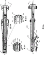
The perspective view that Fig. 1 a-1p is the pedal plate (footplate) according to the embodiment of the present invention.
Fig. 2 a shows the right side perspective view of the expanding unit of assembling fully according to the embodiment of the present invention.
The right side perspective view that Fig. 2 b exposes for the part of the expanding unit according to the embodiment of the present invention.
The right side perspective view that Fig. 3 a exposes for the part of the expanding unit according to the embodiment of the present invention.
Fig. 3 b is the amplification window view according to the part of the expanding unit in Fig. 3 a of the embodiment of the present invention.
Fig. 4 a is the perspective view according to the distal portions of the expanding unit of the embodiment of the present invention.
Fig. 4 b is the amplification window view according to the part of the expanding unit in Fig. 4 a of the embodiment of the present invention.
Fig. 5 a-5f is the perspective view according to the stopper of the embodiment of the present invention.
The right side perspective view that Fig. 6 a exposes for the part of the expanding unit according to the embodiment of the present invention.
Fig. 6 b is the amplification window view according to the part of the expanding unit in Fig. 6 a of the embodiment of the present invention.
The right side perspective view that Fig. 6 c exposes for the part of the expanding unit according to the embodiment of the present invention.
The top plan view that Fig. 7 a exposes for the part of the expanding unit according to the embodiment of the present invention.
Fig. 7 b is the amplification window view according to the part of the expanding unit in Fig. 7 a of the embodiment of the present invention.
Fig. 7 c is the amplification window view according to the part of the expanding unit in Fig. 7 a of the embodiment of the present invention.
The perspective view of the distal portions that Fig. 8 exposes for the part according to the expanding unit of the embodiment of the present invention.
Fig. 9 a is the perspective view according to the distal portions of the expanding unit of the embodiment of the present invention.
Fig. 9 b is the amplification window view according to the part of the expanding unit in Fig. 9 a of the embodiment of the present invention.
Fig. 9 c is the profile perspective according to the far-end of the expanding unit of the embodiment of the present invention.
Fig. 9 d is the perspective view of a part of differentially expanding of distally C shape pipe when allowing stopper therefrom to pass illustrated according to the embodiment of the present invention.
Figure 10 a is the right side perspective view according to the local exposed portions serve of the expanding unit of the embodiment of the present invention.
Figure 10 b is the amplification window view according to the part of the expanding unit in Figure 10 a of the embodiment of the present invention.
Figure 11 is the right side perspective view according to the local exposed portions serve of the expanding unit of the embodiment of the present invention.
Figure 12 is the right side perspective view according to the local exposed portions serve of the expanding unit of the embodiment of the present invention.
Figure 13 is the right side perspective view according to the local exposed portions serve of the expanding unit of the embodiment of the present invention.
Figure 14 is the right side perspective view according to the local exposed portions serve of the expanding unit of the embodiment of the present invention.
The right side perspective view that Figure 15 a exposes for the part of the expanding unit according to the embodiment of the present invention.
Figure 15 b is the amplification window view according to the part of the expanding unit in Figure 15 a of the embodiment of the present invention.
Figure 16 is the right side perspective view according to the local exposed portions serve of the expanding unit of the embodiment of the present invention.
The right side perspective view that Figure 17 a exposes for the part of the expanding unit according to the embodiment of the present invention.
Figure 17 b is the right side perspective view according to the local exposed portions serve of the expanding unit of the embodiment of the present invention.
The backside perspective view that Figure 18 exposes for the part of the expanding unit according to the embodiment of the present invention.
Figure 19 is the right side perspective view according to the local exposed portions serve of the expanding unit of the embodiment of the present invention.
Figure 20 is the top plan view according to the local exposed portions serve of the expanding unit of the embodiment of the present invention.
Figure 21 a is the cross-sectional right side view according to the local exposed portions serve of the expanding unit of the embodiment of the present invention.
Figure 21 b is the top side sectional view according to the local exposed portions serve of the expanding unit of the embodiment of the present invention.
Figure 21 c and 21d are the amplification window view according to the part of the expanding unit in Figure 21 a of the embodiment of the present invention.
Figure 22 a is the cross-sectional right side view according to the local exposed portions serve of the expanding unit of the embodiment of the present invention.
Figure 22 b is the top side sectional view according to the local exposed portions serve of the expanding unit of the embodiment of the present invention.
Figure 22 c and 22d are the amplification window view according to the part of the expanding unit in Figure 22 b of the embodiment of the present invention.
Figure 22 e is the amplification window view according to the part of the expanding unit in Figure 22 a of the embodiment of the present invention.
Figure 23 a is the cross-sectional right side view according to the local exposed portions serve of the expanding unit of the embodiment of the present invention.
Figure 23 b is the top side sectional view according to the local exposed portions serve of the expanding unit of the embodiment of the present invention.
Figure 23 c and 23d are the amplification window view according to the part of the expanding unit in Figure 23 b of the embodiment of the present invention.
Figure 23 e is the amplification window view according to the part of the expanding unit in Figure 23 a of the embodiment of the present invention.
Figure 24 a is the cross-sectional right side view according to the local exposed portions serve of the expanding unit of the embodiment of the present invention.
Figure 24 b is the top side sectional view according to the local exposed portions serve of the expanding unit of the embodiment of the present invention.
Figure 24 c-24f is the amplification window view according to the part of the expanding unit in Figure 24 b of the embodiment of the present invention.
Figure 25 a is the cross-sectional right side view according to the local exposed portions serve of the expanding unit of the embodiment of the present invention.
Figure 25 b is the top side sectional view according to the local exposed portions serve of the expanding unit of the embodiment of the present invention.
Figure 25 c-25d is the amplification window view according to the part of the expanding unit in Figure 25 b of the embodiment of the present invention.
Figure 26 a is the cross-sectional right side view according to the local exposed portions serve of the expanding unit of the embodiment of the present invention.
Figure 26 b is the top side sectional view according to the local exposed portions serve of the expanding unit of the embodiment of the present invention.
Figure 26 d and 26f are the amplification window view according to the part of the expanding unit in Figure 26 a of the embodiment of the present invention.
Figure 26 g is the amplification vertical cross-section figure through the part of the expanding unit in Figure 26 a according to the embodiment of the present invention.
Figure 26 c and 26e are the amplification window view according to the part of the expanding unit in Figure 26 b of the embodiment of the present invention.
Figure 27 is the left side perspective view according to the local exposed portions serve of the expanding unit of the embodiment of the present invention.
Figure 28 a is the cross-sectional right side view according to the local exposed portions serve of the expanding unit of the embodiment of the present invention.
Figure 28 b is the downside view according to the expanding unit of the embodiment of the present invention.
Figure 29 a is the cross-sectional right side view according to the local exposed portions serve of the expanding unit of the embodiment of the present invention.
Figure 29 b is the top side sectional view according to the local exposed portions serve of the expanding unit of the embodiment of the present invention.
Figure 29 d, 29e and 29f are the amplification window view according to the part of the expanding unit in Figure 29 a of the embodiment of the present invention.
Figure 29 c is the amplification vertical cross-section figure through the part of the expanding unit in Figure 29 a according to the embodiment of the present invention.
Figure 30 a is the cross-sectional right side view according to the local exposed portions serve of the expanding unit of the embodiment of the present invention.
Figure 30 b-30c is the amplification window view according to the part of the expanding unit in Figure 30 a of the embodiment of the present invention.
Figure 31-41 show the sequential steps when launching the opening that closing device forms through blood vessel with shutoff with expanding unit according to the embodiment of the present invention.
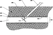
Figure 42-43 show according to the closing device in the shutoff relation between the embodiment of the present invention and opening that form through blood vessel (being to launch the configuration position after closing device launches).
The specific embodiment
Below will introduce in detail the preferred embodiments of the present invention, each example shown in the drawings.
According to embodiments of the invention, provide and comprised that pedal plate 110 is (as described below, this pedal plate can comprise the embodiment of any pedal plate), the closing device 100 of stopper 111 and wire rod 120, and this closing device 100 can be for shutoff or the closed opening formed through biological tissue in order to control (or prevent or stop) bleed (or other biological fluid or tissue flow), (this point of puncture comprises the opening formed through blood vessel wall and the anatomic passages of bordering on the opening formed through biological tissue to described opening such as the point of puncture formed for percutaneous, described anatomic passages extends to the skin be stacked and placed on blood vessel through tissue), otch or through such as blood vessel, the biological tissues such as organ and the opening of some other type of forming.For example, the closing device 100 of the embodiment of the present invention can be for the shutoff arteriotomy, and this arteriotomy is that (through the skin of next-door neighbour's blood vessel top and the unlimited anatomic passages of tissue) forms such as the opening in the tremulous pulsies such as femoral artery or otch and the point of puncture that formed together with percutaneous by the clinician in diagnostic or curative endovascular surgical procedures.
According to embodiments of the invention, closing device 100 can launch the configuration position or launch the configuration position after closing device launches before closing device launches.Launch the configuration position before closing device launches and comprise such configuration position:, closing device 100 is present in the expanding unit 200 (for closing device 100 being deployed into to for example opening of blood vessel wall, with shutoff blood vessel and then prevention blood flow, crossing opening) of the embodiment of the present invention.Launch the configuration position after closing device launches and comprise such configuration position:, closing device 100 is present in the opening on blood vessel wall and passes this opening.
Illustrate more all sidedly below with reference to the accompanying drawings before closing device 100, closing device launch that launching configuration position, closing device launches configuration position, expanding unit 200 and launch the method for closing device 100 with the opening on the shutoff blood vessel wall after launching.
Now, refer to from start to finish the accompanying drawing of same section with reference to same numeral, Fig. 1 a shows the pedal plate 110 according to the embodiment of the present invention.The present embodiment shows the pedal plate 110 that launches the configuration position before closing device launches, wherein in the far-end of pedal plate 110 in expanding unit 200 (not shown).Pedal plate 110 comprises the distal portions (overall structure) of the single length of the wire rod 120 that bends to the elongated configuration that is rendered as long U-loop 30.Long U-loop 30 comprises far-end 102 and a pair of laterally spaced longitudinal extension lower limb 31,32 of unlimited near-end 101, sealing.The far-end 102 of sealing and should be roughly coplanar in common plane and be roughly parallel to the longitudinal axis of the control housing 210 of expanding unit 200 to laterally spaced longitudinal extension lower limb 31,32.The closed distal end 102 of long U-loop 30 limits vertical end of the elongated configuration of bent wire.Long U-loop should comprise free lower limb 31 and connection leg 32 to laterally spaced longitudinal extension lower limb 31,32, this freely moves back unlimited near-end 101 sides that 31 free near-end is positioned at long U-loop.The coupling part 33 of shape is connected with wire rod 120 twist.The coupling part 33 of shape can be operable at bending area permanent (plasticity) distortion occurs twist.Wire rod 120 is along the longitudinal axis of controlling housing 210.Wire rod 120 is close to pedal plate 110, and the coupling part 33 of shape is in extension between engagement leg 34 (and laterally spaced longitudinal extension lower limb 31,32 is roughly coplanar) and wire rod 120 at the unlimited near-end 101 of long U-loop 30 twist.
Forward Fig. 1 b to, show the pedal plate 110 according to the embodiment of the present invention.The present embodiment shows (in Fig. 1 a) pedal plate 110 and launch the configuration position after closing device launches, and wherein the part of pedal plate 110 leans on the inwall of blood vessel (for example tremulous pulse, not shown) below percutaneous puncture point (not shown).The coupling part 33 of shape comprises bending area twist, and wherein permanent (plasticity) distortion occurs this bending area.Blind end 102 and should roughly keep coplanar in common plane to laterally spaced longitudinal extension lower limb 31,32, and be approximately perpendicular to the longitudinal axis of puncture and be roughly parallel to the plane of the inwall of blood vessel.Wire rod 120 extends to anatomic passages from the opening that the coupling part 33 of shape is passed blood vessel wall towards nearside twist, and wherein wire rod 120 (before being unfolded device 200 cuttings bending) is along the longitudinal axis of puncture.
Forward Fig. 1 c to, show the pedal plate according to the embodiment of the present invention.The present embodiment shows the pedal plate 110 ' that launches the configuration position before closing device launches, wherein in the far-end of this pedal plate 110 ' in expanding unit 200 (not shown).Pedal plate 110 ' comprises the distal portions (overall structure) of the single length of the wire rod 120 that bends to the elongated configuration that is rendered as long U-loop 30 '.Long U-loop 30 ' comprises near-end 101 ' and a pair of laterally spaced longitudinal extension lower limb 31 ', 32 ' of unlimited far-end 102 ', sealing.The near-end 101 ' of the sealing of long U-loop 30 ' limits vertical near-end of the elongated configuration of bent wire.Being somebody's turn to do of long U-loop 30 ' comprise free lower limb 31 ' and connection leg 32 ' to laterally spaced longitudinal extension lower limb, and the free distal end of this free lower limb 31 ' is positioned at the unlimited far-end 102 ' side of long U-loop 30 '.Show the coupling part 33 ' that bends to arc and the middle lower limb 34 ' that comprises bending area.The coupling part 33 ' that bends to arc is between connection leg 32 ' and middle lower limb 34 ' and extends at unlimited far-end 102 ', and limits vertical far-end of bent wire configuration.Long U-loop 30 ' is roughly coplanar in common plane with the coupling part 33 ' that bends to arc, and coaxial with the longitudinal axis of the control housing 210 of expanding unit 200.The coupling part 33 ' that bends to arc is medially crooked towards connection leg 32 ' and the middle lower limb 34 ' that is clipped between free lower limb 31 ' and connection leg 32 '.The distal portions of lower limb in the middle of free lower limb 31 ' and connection leg 32 ' are fixed to by tack-weld 35 respectively.Tack-weld 35 can comprise electron-beam point plumb joint or laser spot welding joint.The far-end of free lower limb is stopped (but can be longer or shorter) at this free lower limb by the some place of lower limb 34 ' in the middle of spoting weld.Middle lower limb 34 ' extends and extends in the below of near-end 101 ' (but can extend in the top of near-end 101 ') towards nearside towards the near-end 101 ' of sealing, and surpass the near-end 101 ' of sealing at a certain angle and extend to wire rod 120 with respect to above-mentioned common plane, wherein wire rod 120 is positioned at the nearside of pedal plate 110 '.
Forward Fig. 1 d to, show the pedal plate 110 ' according to the embodiment of the present invention.The pedal plate 110 ' that the present embodiment shows in Fig. 1 c launches the configuration position after closing device launches, and wherein the part of pedal plate 110 ' leans on the inwall of blood vessel (for example tremulous pulse, not shown) below percutaneous puncture point (not shown).Permanent (plasticity) distortion occurs in bending area (proximal edge of the tack-weld 35 of lower limb 34 ' in the middle of being preferably placed at).Long U-loop 30 ' and the coupling part 33 ' that bends to arc keep roughly coplanar in common plane, and are approximately perpendicular to the longitudinal axis of puncture and are roughly parallel to the plane of the inwall of blood vessel.Wire rod 120 extends to the inside of anatomic passages through the opening blood vessel wall from bending area towards nearside, wherein wire rod 120 (before being unfolded device 200 cuttings bending) is along the longitudinal axis of puncture.
Forward Fig. 1 e-1f to, show the pedal plate 710 according to the embodiment of the present invention.Except free lower limb 731 and tack-weld 735, the embodiment of these pedal plates is similar to respectively the pedal plate shown in Fig. 1 c-1d.As shown in Fig. 1 e and Fig. 1 f, free lower limb 731 comprises hook-shaped far-end, and tack-weld 735 only is fixed to middle lower limb 734 on connection leg 732.The coupling part 733 that also shows long U-loop 730, near-end 1101 and far-end 1102 and bend to arc.
Forward Fig. 1 g to, show the pedal plate 810 according to the embodiment of the present invention.The present embodiment shows the pedal plate 810 that launches the configuration position before closing device launches, wherein in the far-end of this pedal plate 810 in expanding unit 200 (not shown).Pedal plate 810 is piece or the bar rod 837 longitudinally be shaped.This rod 837 comprises longitudinal hole 840, arc top surface 838, lower arcuate surface (not shown) (select as another kind, end face and bottom surface can be roughly plane), all side surfaces 839, near-end 2101 and far-end 2102.Wire rod 120 by the distal portions 2102 of the arc top surface 838 with bar rod 837, be connected (also can be connected with lower arcuate surface) flat or pressure-sizing far-end 836 and be connected (being preferably welding) with bar rod 837.The far-end 836 of pressure-sizing extends to mid portion 834 towards nearside, and this mid portion 834 extends to the below (but can extend above near-end 2101) of near-end 2101 through hole 840 towards nearside.
Forward Fig. 1 h to, show the pedal plate 810 according to the embodiment of the present invention.The pedal plate 810 that the present embodiment shows in Fig. 1 g launches the configuration position after closing device launches, and wherein the part of pedal plate 810 leans on the inwall of blood vessel (for example tremulous pulse, not shown) below percutaneous puncture point (not shown).Mid portion 834 comprises bending area, and wherein permanent (plasticity) distortion occurs this bending area.Mid portion 834 extends through hole 840 towards nearside.Wire rod 120 extends to anatomic passages from middle part 834 through the opening blood vessel wall at nearside, and wherein wire rod 120 (before being unfolded device 200 cuttings bending) is along the longitudinal axis of puncture (not shown).
Forward Fig. 1 i-1j to, show the pedal plate 1010 according to the embodiment of the present invention.Except the far-end 1036 of wire rod 120, the embodiment of these pedal plates is similar to respectively the pedal plate shown in Fig. 1 g-1h.Far-end 1036 is neither flat (but having the circular cross-section identical with the remainder of wire rod) that neither pressure-sizing.Far-end 4102 place's wire rods 120 at the bar rod 1037 of pedal plate 1010 are longitudinally fixed between (being preferably welding) distal portions and arc top surface 1038 at wire rod 120 interfacial both sides.Also show near-end 4101, mid portion 1034, hole 1040 and all side surfaces 1039.
Forward Fig. 1 k to, show the top plan view according to the pedal plate 910 of the embodiment of the present invention.The present embodiment shows the pedal plate 910 that launches the configuration position before closing device launches, wherein in the far-end of this pedal plate 910 in expanding unit 200 (not shown).Pedal plate 910 comprises piece or the bar rod 937 longitudinally be shaped.Bar rod 937 comprises the end face 938 of general planar, bottom surface (not shown), all side surfaces 939, near-end 3101 and the far-end 3102 of general planar.Wire rod 120 is connected with bar rod 937 by the balled end 936 of bracket 941 connections of the flat top 938 with bar rod 937 (also can be connected with planar bottom surface).As shown in Fig. 1 l, bracket 941 is " C " font to allow pedal plate 910 actions.The part of wire rod 120 can be seated in the arc-shaped recess part 942 of end face 938 of bar rod 937.
Forward Fig. 1 l to, show the downside view according to the pedal plate 910 of the embodiment of the present invention.The pedal plate 910 that the present embodiment shows in Fig. 1 i launches the configuration position after closing device launches, and wherein the part of this pedal plate 910 leans on the inwall of blood vessel (for example tremulous pulse, not shown) below percutaneous puncture point (not shown).There is not bending area in the present embodiment of pedal plate 910.Bar rod 937 can be operable to the structure/mechanism that follows ball 936 and bracket 941 and rotate.Can set up pivot point like this, near-end 3101 is rotated down and far-end 3102 rotates up (selecting as another kind can be according to alternative structure along contrary direction rotation) around set up pivot point towards proximal direction (proximal direction) towards distal direction (distal direction) around set up pivot point.Fig. 1 l shows pedal plate 910 in its full action or position of rotation.Wire rod 120 extends to anatomic passages from ball 936 through the opening blood vessel wall at nearside, and wherein wire rod 120 (before being unfolded device 200 cuttings bending) is along the longitudinal axis of puncture (not shown).Show the bottom surface 943 of general planar, it also can comprise ledge, and this ledge comprises the bottom of female 942 of the end face 938 of bar rod 937.
Forward Fig. 1 m to, show the top plan view according to the pedal plate 1110 of the embodiment of the present invention.The present embodiment shows the pedal plate 1110 that launches the configuration position before closing device launches, wherein in the far-end of this pedal plate 1110 in expanding unit 200 (not shown).Pedal plate 1110 comprises piece or the bar rod 1137 longitudinally be shaped.Bar rod 1137 is " y font ", and comprises the end face 1138 of general planar, bottom surface 1143 (not shown), all side surfaces 1139, near-end 5101, the far-end 5102 of general planar and two roughly coplanar lower limb 1144 and 1145 (not shown) that extend towards nearside that separated by slot 1146.The linkage of wire rod 120 by comprising hooked end 1136 is connected with bar rod 1137, semi-circular portions 1141 connections on the end face 1138 (also can be connected with planar bottom surface) of this hooked end 1136 and the general planar that is arranged on bar rod 1137.
Forward Fig. 1 n to, show the downside view according to the pedal plate 1110 of the embodiment of the present invention.The pedal plate 1110 that the present embodiment shows in Fig. 1 m launches the configuration position after closing device launches, and wherein the part of this pedal plate 1110 leans on the inwall of blood vessel (for example tremulous pulse, not shown) below percutaneous puncture point (not shown).There is not bending area in the present embodiment of pedal plate 1110.Bar rod 1137 can be operable to follows linkage and rotates, this will set up pivot point, and near-end 5101 is rotated down and far-end 5102 rotates up (selecting as another kind can be according to alternative structure along contrary direction rotation) around set up pivot point towards proximal direction towards distal direction around set up pivot point.Fig. 1 n shows pedal plate 1110 in its full action or position of rotation.Wire rod 120 extends to anatomic passages towards proximal direction through the opening on blood vessel wall, and wherein wire rod 120 (before being unfolded device 200 cuttings bending) is along the longitudinal axis of puncture (not shown).Also show the bottom surface 1143 of general planar.
Forward Fig. 1 o-1p to, show the pedal plate 1210 according to the embodiment of the present invention.Except the distal hooked 1236 of wire rod 120 and through hole 1241 and slot 1246 these configuration far-ends 1236 of installation, the embodiment of these pedal plates is similar to respectively the pedal plate embodiment shown in Fig. 1 m-1n.Distal hooked 1236 is installed on bar rod 1237 through hole 1241.Distal hooked 1236 extends to the end face 1238 of general planar from the bottom surface 1243 of general planar through hole 1241, then hook slot 1246, thus pedal plate 1210 is fixed on wire rod 120.Also show the end face 1238 of bar rod 1237, far-end 6102 and near-end 6101, general planar, the bottom surface 1243 of general planar, all side surfaces 1239, two roughly coplanar lower limb 1244 and 1245, slot 1246 and the wire rods 120 that extend towards proximal direction.
According to embodiments of the invention, the expanding unit 200 below with reference to the accompanying drawing explanation with the closing device 100 of the embodiment of the present invention.As the example of spendable pedal plate, specifically pedal plate 110 ' is done to the introduction about pedal plate.Yet should be understood that can be with comprising that above introduced any pedal plate embodiment substitutes pedal plate 110 '.
Forward Fig. 2 a-4b to, (Fig. 2 a shows the expanding unit 200 of assembling fully to show right side view according to the expanding unit 200 with near-end 10 and far-end 20 of the embodiment of the present invention, view is exposed in the part that Fig. 2 b, Fig. 3 and Fig. 4 are expanding unit 200, and default some part is to expose other parts of expanding unit 200).According to embodiments of the invention, before in being deployed into the blood vessel that needs shutoff, pedal plate 110 ' is positioned at the far-end 20 of expanding unit 200 and is present in outside distally C shape pipe 201, and the remainder of wire rod 120 is near the far-end pedal plate 110 ' in expanding unit 200 and end at wire ferrule 250 places and (see that the Fig. 7 that the following describes a).Pedal plate 110 ' with respect to the longitudinal axis of the control housing 210 of expanding unit 200 in shaft core position.(seeing Fig. 4 a-4b) as described below, the near-end 101 of pedal plate 110 ' is against the far-end of inboard distally C shape pipe 202.
Forward Fig. 5 a-5f to, show the stopper 111 according to the embodiment of the present invention.These embodiment show coning shape and comprise distal portions (or end) 104 and the stopper 111 of proximal part (or end) 103, and wherein the diameter of the distal portions 104 of stopper is less than the diameter of the proximal part 103 of stopper.As described below, the maximum gauge of stopper 111 is greater than the diameter in the main pipe zone 205 of expanding unit.Forward Fig. 5 a to, show the right side view of stopper 111.Forward Fig. 5 b to, show the top side view of stopper 111.Forward Fig. 5 c to, show the left side upset view of stopper 111.Forward Fig. 5 d to, show the front view with the stopper 111 of inner chamber 105.Forward Fig. 5 e to, show the underneath side elevation view of stopper 111.Forward Fig. 5 f to, show the lateral side view with the stopper 111 of inner chamber 105.According to embodiments of the invention, one or more " otch " or " cavity " can be set at the far-end of stopper 111, in order to allow the nested pedal plate 110 ' of stopper 111 and wire rod 120.In addition, according to embodiments of the invention, one or more " otch " or " cavity " can be set at the near-end of stopper 111, in order to allow the insert 112 (seeing Figure 10 b) of the far-end of ejector sleeve 212 to keep the Spin Control of stopper 111 with respect to pedal plate 110 '.Various embodiments of the present invention have been conceived combination with various " otch " or without any the stopper 111 of " otch ".
Forward Fig. 6 a-6c to, show the right side view exposed according to the part of the expanding unit 200 of the embodiment of the present invention.According to embodiments of the invention, in being deployed into the blood vessel that needs shutoff before (being to launch the configuration position before closing device launches), stopper 111 is near pedal plate 110 ' and along the longitudinal axis of wire rod 120.In the distal portions of the distally, the outside of expanding unit 200 pipe 211 (it is controlling the inside of housing 210), stopper 111 is adjacent to ejector sleeve 212 in distally.
Forward Fig. 7 a-7c to, show the top view exposed according to the part of the expanding unit of the embodiment of the present invention.The present embodiment shows wire rod 120 and is positioned at expanding unit 200.Wire rod 120 110 ' stretches through longitudinal axis hole 105 (not shown) stopper 111 along the direction from as far as near from pedal plate.Wire rod 120 is managed 202 (not shown) and is sheared the inboard near-end of managing 224 (in ejector sleeves 212) and then extending to wire ferrule 250 through inboard distally C shape from pedal plate 110 '.
According to embodiments of the invention, below will roughly from far-end 20 to near-end, the closing device expansion of the expanding unit 200 of the 10 explanation embodiment of the present invention, launch configuration (acquiescence configuration).Usually, in suitable figure, the clamp device of allowing (for example screw) indicates label 226, and packing ring indicates label 214.Expanding unit 200 below will be described and launch the using method of the closing device 100 of configuration position after closing device launches.
Rotate back into Fig. 2 a-2b, these embodiment show the expanding unit 200 that comprises distally, outside C shape pipe 201.The far-end of distally, outside C shape pipe 201 comprises nose end or the end portion 203 of constriction.This nose end of distally, outside C shape pipe 201 divides 203 to be for holding the part of pedal plate 110 ' (not shown) in expanding unit.The remainder of distally, outside C shape pipe 201 holds inboard distally C shape pipe 202 (seeing Fig. 8) and wire rod 120, and the bottom of this distally, inboard C shape pipe 202 comprises longitudinal opening 204.These distally C shapes pipe nests together with one heart and forms following main pipe zone 205.
Forward Fig. 8, Fig. 9 a-9c to, show the distal end view according to the expanding unit 200 of the embodiment of the present invention.Fig. 9 b shows the 406,Gai ingate, ingate 406 entered into by distally, outside C shape pipe 201 and the inboard distally C shape pipe 202 main pipe zones 205 that form (seeing Fig. 9 c) and is used as the blood mark channel.Ingate 406 is near the far-end of distally, outside C shape pipe 201.In addition, distally, outside C shape pipe 201 and inboard distally C shape pipe 202 comprise respectively the side opening 206 (gas outlet) of aiming at concentrically with respect to one another.Side opening 206 is away from stopper 111 (not shown) close to pedal plate 110 '.Side opening 206 can be operable to as blood flows through blood mark channel 205 from blood vessel towards nearside and flow to 406De gas outlet, ingate.Blood flows through distal portions that side opening 206 shows pedal plate and expanding unit 200 intravasation (not shown, as below will to illustrate) towards nearside.In addition, main pipe zone 205 can be operable to as the spreading area that launches stopper 111, thus wherein distally C shape pipe can be operable to expand partly and separate produce allow stopper 111 therefrom by and intravasation launches the irreversible non-nested state (seeing Fig. 9 d) of rear configuration position.
According to embodiments of the invention, the view of the distal portions that Fig. 9 a and 9b are expanding unit 200, the cutaway view of the distal portions that Fig. 9 c is expanding unit 200, Fig. 9 c shows the nested configuration of 201 (comprising guidewire lumen 300) of outside distally C shape pipe and inboard distally C shape pipe 202, manages 202 according to this distally, outside C shape pipe 201 of embodiments of the invention and inboard distally C shape and forms together blood mark channel 205 and the passage of nested wire rod 120 therein.Distally, outside C shape pipe 201 comprises guidewire lumen 300 (seeing Fig. 9 c), and this guidewire lumen 300 comprises that proximal guidewire exports 207 and (sees Fig. 9 a) and the distal guide entrance 301 (seeing Fig. 9 b and 9c) for inserting the seal wire (not shown).Proximal guidewire outlet 207 is away from stopper 111 closing device close to pedal plate 110 ' launches front expanded position.Distal guide entrance 301 is positioned at the farthest (203 places are divided in the nose end that is positioned at far-end) of expanding unit 200.
According to embodiments of the invention, distally, outside C shape pipe 201 and inboard distally C shape pipe 202 can move along the longitudinal independently of one another, be that distally C shape pipe can be operable to along the longitudinal axis of wire rod 120 and (for example slides independently, as described below, when the inner chamber in tremulous pulse is inner, permission and the 110 ' action of auxiliary pedal plate are to the substantially vertical position of longitudinal axis with respect to controlling housing 210).
Forward Figure 10 a-10b to, show the right side view exposed according to the part of the expanding unit 200 of the embodiment of the present invention.The present embodiment shows outside distally C shape pipe 201 and inboard distally C shape pipe 202 near-end separately and just terminates in outside nearside pipe 211 (inboard distally C shape pipe 202 terminates in back-up ring 325 places (see Figure 11, below will illustrate) and manages 201 and a little more rely on nearside than terminating in distally, outside C shape that back-up ring 324 (seeing Figure 11) locates).Outside nearside pipe 211 by control housing 210 around, conversely this control housing 210 partly by skin flange assembly 222 (not shown) that comprise distal portions 221 and proximal part 303 (seeing Fig. 2 b) around.Skin flange assembly 222 (not shown) can be operable to along the longitudinal axis of wire rod 120 and along the Outboard Sections of controlling housing 210 and the Outboard Sections of distally C shape pipe and slide in distally.Stopper 111 is adjacent to the far-end of insert 112 and ejector sleeve 212 in distally, this ejector sleeve 212 mainly is located immediately at inboard nearside pipe 213 (it is positioned at outside nearside pipe 211 grades), and this inboard nearside pipe 213 roughly extends to the near-end 10 (seeing Fig. 6 a-6b) of expanding unit 200 towards proximal direction.The nearside pipe can be operable to along the longitudinal axis of wire rod 120 and slide independently.
Forward Figure 11-13 to, show the right side view that expose the part of the expanding unit 200 of the embodiment of the present invention.The present embodiment shows ejector sleeve 212, and this ejector sleeve 212 is positioned at nearside pipe (211,213), and the far-end of ejector sleeve 212 by back-up ring 325 around and near-end by adjusting key 326, supported.Ejector sleeve 212 extends from ejector sleeve insert 112 (it is by means of be fixed to the far-end of ejector sleeve 212 such as suitable means such as welding) towards proximal direction through packing ring 214 (its be welded on ejector sleeve 212 and its proximal face close to the far-end of sliding cylinder 215), and outstanding main body through sliding cylinder 215 makes the nearest end of ejector sleeve 212 be close to the most proximal end close to sliding cylinder.Far-end in top side, ejector sleeve 212 has the opening 219 (for slot) extended towards proximal direction at the point of the nearside of the far-end of ejector sleeve 212 a little from just.Shear pipe 224 and be housed in one heart in ejector sleeve 212, these shearings pipe 224 proximal face of the inclination from ejector sleeve insert 112 350 (seeing Figure 30 c) are managed the most proximal end nearside of the most proximal end of ejector sleeve 212 (slightly) towards proximal direction to returning to extend to shear.The near-end of shearing pipe 224 has the lid 216 be fixed to the upper.Ejector sleeve 212 and shearing pipe 224 can be operable to along the longitudinal axis of wire rod 120 and slide towards distally.Ejector sleeve 212 can be operable to and promote after stopper 111 enters closing device expansion as described below through main pipe zone 205 to launch the configuration position.As described below, shearing pipe 224 (together with ejector sleeve inserts 112) can be operable to by wire rod 120 bendings and after fractureing into vessel sealing and launch configuration.
Forward Figure 14-16 to, show the right side view exposed according to the part of the expanding unit 200 (being depicted as default location) of the embodiment of the present invention.According to embodiments of the invention, be provided with the constant force spring that comprises a plurality of horizontal constant force springs, described a plurality of horizontal constant force springs comprise left laterally constant force spring 125 and right laterally constant force spring 125.(left and right) laterally constant force spring 125 comprises respectively flat 227 and wind spring part 228.(left and right) horizontal constant force spring 125 wind spring part 228 separately is positioned at partly respectively the distal portions of (being nested in) control housing 210 and (sees Figure 15 a), and cover (accommodating within it) (seeing Figure 14) by the distal portions 221 of skin flange assembly 222 in the left and right sides.(left and right) laterally the flat 227 of constant force spring 125 is stretched over the inboard proximal part 303 of the left and right sides of skin flange assembly 222 along straight ground, the outside (respectively in the left and right sides) of controlling housing 210 (difference) from wind spring part 228 towards proximal direction, the clamp device 226 that flat 227 is allowed is fastened on this place (seeing Figure 14).Laterally constant force spring can be operable to and utilize the constant skin flange assembly 222 that far moves to power towards distally.Laterally constant force spring also can be operable to the outer surface of patient's skin, apply constant far to power.In addition, laterally constant force spring can be operable to wire rod 120 and apply constant proximad tensile force.This constant proximad tensile force makes pedal plate 110 ' lean on inwall 403 (not shown) of blood vessel, and wherein as described below, the some place leaned at pedal plate 110 ' produces datum mark.
According to embodiments of the invention, be provided with the constant force spring that comprises constant force spring 135 and lower constant force spring 135, described upper constant force spring 135 and lower constant force spring 135 comprise respectively flat 230 and wind spring part 229.Upper and lower constant force spring 135 wind spring part 229 separately is positioned at (above and below) outside that (being nested in) controls the far-end of housing 210, and covers (accommodating within it) (seeing Figure 14) by the distal portions 221 of skin flange assembly 222.The flat 230 of upper and lower constant force spring 135 extends from wind spring part 229 separately (being positioned at the distal portions of controlling housing 210) towards proximal direction and stretches along the outside (respectively in upper and lower both sides) of control housing 210 straightly, and for example, be fastened to about middle part (seeing Figure 16) of sliding cylinder 215 (respectively in top and bottom) by means of the clamp device of allowing (, screw 226 and packing ring 214).Upper and lower constant force spring 135 can be operable to by applying to sliding cylinder 215 and constant far to power, towards distal direction, move sliding cylinder 215.Sliding cylinder 215 can be operable to by upper and lower constant force spring 135 and apply constant far to power, towards distal direction propelling ejector sleeve 212, wherein stopper 111 percutaneously being pushed to percutaneous puncture point (seeing Figure 39) and then arrive the expansion configuration position after closing device launches to sliding cylinder 215.The datum mark (as described below) produced by wire rod 120 and pedal plate 110 ' is controlled the expansion configuration position after this closing device launches, thus the opening on the shutoff blood vessel wall.
Forward Figure 17 a, 17b and 18 to, show the near-end 10 (right lateral side that expose part and lateral side view) according to the expanding unit 200 of the embodiment of the present invention.The present embodiment shows the extrusion lever Handleset 231 of expanding unit 200.This extrusion lever Handleset 231 comprises extrusion lever handle 232, remains on interior button 233 and the connecting rod 235 of retainer plate 234 of extrusion lever handle 232.Button 233 can be in the interior slip of guard ring part 234.The near-end of connecting rod 235 is (by unci or the C shape parts 266 of making progress, not shown) be installed to removedly (by means of joint pin 256, not shown) bottom of sliding cylinder 215 is (as described below, when extruding extrusion lever handle 232, mechanical energy is delivered to sliding cylinder and produce sliding cylinder far to movement).The other end of connecting rod 235 (bottom) is installed on extrusion lever handle 232 by means of joint pin mechanism 236.By hooked end 237 transversely, extrusion lever handle 232 is installed on the proximal part 303 of skin flange assembly 222 (in the left and right sides of device) removedly.
Forward Figure 19 to, show the right side view that exposes be arranged according to the parts of the proximal part of the expanding unit 200 of the embodiment of the present invention.The present embodiment shows the sliding cylinder assembly that comprises sliding cylinder 215 and cut off lever 218, and this cut-out lever 218 comprises by means of joint pin mechanism 238 and is hinged to the proximal part on sliding cylinder 215.Cut off lever 218 distal portions can around joint pin mechanism 238, along vertical direction, the longitudinal axis away from wire rod 120 (not shown) hingedly moves.The near-end that sliding cylinder 215 is positioned at wire rod 120 (not shown) is installed to the distally of the position on wire ferrule 250 and is housed in control housing 210 (not shown).The sliding cylinder assembly can be operable to along the longitudinal axis of wire rod 120 (not shown) and slide towards distally.
Forward Figure 20 to, show the top view exposed be arranged according to the parts of the proximal part of the expanding unit 200 of the embodiment of the present invention.The present embodiment shows wire ferrule 250, and it comprises long U-shaped structure.This long U-shaped structure comprises the near-end 251 of sealing and unlimited far-end 252.Wire ferrule 250 is positioned at inboard nearside pipe 213 (not shown), and can be operable to along the longitudinal axis of wire rod 120 (not shown) and longitudinally slide.Roughly extend to the outstanding right side near-end through wire ferrule 250 of release shaft 239 of the near-end of sliding cylinder 215 towards distally.Also show near-end and control most proximal end 10 places that case lid 240 is positioned at expanding unit 200, this near-end is controlled case lid 240 and is had two laterally spaced lid pusher dogs (right cover pusher dog 241, left cover pusher dog 242) of controlling the distal inner surface extension of case lid 240 from near-end.
According to embodiments of the invention, when diagnostic or curative endovascular surgical operation finishes, the closing device 100 that expanding unit 200 by the embodiment of the present invention launches the embodiment of the present invention, with by stopping up or the shutoff arteriotomy is controlled (or stop or prevent) bleed (method that the following describes expansion).
According to embodiments of the invention, after endovascular surgical operation, preferably after the clinician removes surgical cannula, seal wire 299 (as shown in Figure 31 a) is being retained in to arteriotomy site (blood vessel wall meaned by label 401) (select as another kind, new seal wire 299 can be inserted to arteriotomy).As mentioned above, this seal wire 299 is 306 (inside of patient body) from expose portion 307 (outside of patient body) towards distal extension to unexposed portion, pass the skin penetrating point 397 of patient skin 399, through anatomic passages 407, through arteriotomy 405, and then the inner chamber 404 of intravasation 400.
According to embodiments of the invention, by action, sequentially illustrate that clinician's shutoff in diagnostic or curative endovascular surgical procedures (for example is formed on blood vessel 400 now, such as tremulous pulsies such as femoral artery) wall 401 on the method for opening (arteriotomy), wherein, form the opening on blood vessel wall together with the anatomic passages percutaneous, described anatomic passages and described opening are bordered on and are extended and then (see Figure 31 a) through the surface (percutaneous puncture) that is stacked in the skin on blood vessel towards nearside through subcutaneous tissue.That is the action of Client-initiated action/action and passive generation in both assemblies of closing device 100 and expanding unit 200.Described method comprises provides following system with shutoff opening 405, and described system comprises for shutoff and is formed on the closing device 100 (seeing Figure 43) of the opening (arteriotomy) on the wall 401 of blood vessel 400 and (sees Fig. 2 a) for the expanding unit 200 that closing device 100 is deployed into to the opening (arteriotomy) on the wall 401 that is formed on blood vessel 400.
The embodiment of the method for the present invention of institute's example explanation here is not limited to the order of described action/action, also is not necessarily limited to implement the whole actions that propose.Other sequence of movement or be less than whole actions or action occur can be for implementing embodiments of the invention simultaneously.
Figure 31 a-43 shows according to the distal portions 20 of the expanding unit 200 of the embodiment of the present invention and closing device 100 (as mentioned above, comprise seal wire 299) form the patient's of puncture dissection structure, the i.e. function of skin penetrating point as described below, anatomic passages, arteriotomy etc. for the percutaneous produced before vessel sealing operation.
Forward Figure 31 a to, before bringing into use expanding unit 200, seal wire 299 is in place, and the unexposed portion 306 of seal wire 299 is from patient's skin 399 towards distal direction through skin penetrating point 397 and anatomic passages 407 and then extend to the position of inner chamber 404 inside of blood vessel; And the expose portion 307 of seal wire 299 (bordering on unexposed portion 306) extends so that the outside of expose portion 307 in patient body of seal wire 299 towards proximal direction from patient's skin.
Forward Figure 31 b and Figure 32 to, when starting to launch closing device 100 by expanding unit 200, by seal wire 299 (as mentioned above, in part in the inside of patient body and the local outside at patient body be pre-stored in position) near-end 305 insert seal wire entrance 301 (towards proximal direction).Seal wire 299 is advanced further until the near-end 305 of seal wire 299 exports 207 through seal wire towards proximal direction.When the near-end 305 of seal wire 299 has been given prominence to through seal wire outlet 207 and has been exposed to the device outside, the user firmly grasps and pulls seal wire 299 not change the position of seal wire 299 in patient body inside with any relaxing of eliminating seal wire 299.Then, expanding unit 200 can be crossed seal wire 299 and advance towards distal direction, (plane with respect to the surface of patient skin 399 becomes to be less than the angle of 90 °) is through skin penetrating point 397 so that the far-end 20 of expanding unit 200, continuation moves through the length that percutaneous forms puncture towards distally, through anatomic passages 407 (extending through the subcutaneous tissue 409 be stacked and placed on blood vessel 400), and the inner chamber 404 through arteriotomy 405 and then intravasation 400, (far-end that comprises pedal plate 110 ' and distally C shape pipe) in tube chamber (in inside of the inner chamber 404 of blood vessel 400) until the far-end 20 of expanding unit 200.
According to embodiments of the invention, when blood vessel 400 is inner, arteriotony due to forward, blood flows into main pipe zone 205 (it is as the blood mark channel) via ingate 406 and then towards nearside, arrives side opening 206, can observe drop of blood 408 (" blood labelling ") (seeing Figure 32) at this place.The visible observation of this nearside blood flow indicates pedal plate 110 ' to be positioned at the inside of blood vessel 400 to the user definitely.Then, preferably the far-end more than 20 of expanding unit 200 advances several millimeters to guarantee in the complete inner chamber 404 in blood vessel 400 of pedal plate 110 ', and guarantees that the clinician does not observe wrong blood labelling.Then, the user removes seal wire 299 (by pull seal wire towards nearside, making seal wire pass proximal guidewire outlet 207) fully, then seal wire is placed in to suitable medical waste receptacle, the while user remains on original place by expanding unit 200 and (sees Figure 33, removed seal wire 299, simultaneously the far-end 20 of expanding unit 200 to be retained in the inner chamber 404 of blood vessel 400 be default location).
Figure 21 a-30c relates to by the expanding unit 200 expansion closing devices 100 according to the embodiment of the present invention.These accompanying drawings show action and the automatic function of expanding unit 200, show the displacement in turn (movement) of interior each part of assembly of expanding unit 200 simultaneously.According to embodiments of the invention, Figure 21 a-30c mainly illustrates in the mode of sectional view, in order to can understand better relatively move (percutaneous puncture point, blood vessel etc. are not shown) of interior each part of assembly of expanding unit 200.In these accompanying drawings, longitudinal center line is expressed as consistent with the longitudinal centre line of wire rod 120.These figure also provide " window " of close up view of inside processing of the concrete part (being meaned by dotted line and circle) of expanding unit 200.Show expanding unit such as inboard nearside pipe 213, outside nearside pipe 211, wire ferrule 250, sliding cylinder 215, cut off lever 218, extrusion lever handle 232, connecting rod 235 and button 233, the horizontal constant force spring 125 of left and right sides (comprising wind spring part 228 and flat 227), transversely hooked end 237, upper and lower constant force spring 135 (comprising wind spring part 229 and flat 230), distally, outside C shape pipe 201, inboard distally C shape pipe 202, pedal plate 110 ' (being depicted as whole pedal plate embodiment), stopper 111, the parts such as 203 are divided in the nose end of shearing pipe 224 and distally, outside C shape pipe 201.
As mentioned above, according to embodiments of the invention, Figure 33-43 show each member of distal portions 20 of expanding unit 200 and closing device 100 anatomical structure with respect to patient's percutaneous passage, and skin penetrating point, subcutaneous tissue passage, arteriotomy and blood vessel relatively moves.
Forward Figure 21 a-21d to, show the default location of expanding unit 200 before the user pushes extrusion lever handle 232.Extrusion lever handle 232 is in opening (not extruding) position fully.Extrusion lever handle 232 hingedly is installed to and controls on housing 210 via cylindrical element 271, and this cylindrical element 271 extends from the both sides of controlling housing 210 and be coaxial with the through hole 272 distal flange of extrusion lever handle 232.Connecting rod 235 hingedly is installed on extrusion lever handle 232 and sliding cylinder 215 simultaneously.This connecting rod 235 is power to be delivered to the linkage element of sliding cylinder 215 from extrusion lever handle 232.In this step, inboard nearside pipe 213 and outside nearside pipe 211 are in its distal-most position.The transversely hooked end 237 of extrusion lever handle 232 engages with the hook shape component 255 of the near-end 222 of skin flange assembly 222.Inboard distally C shape manages 202 (not shown) and distally, outside C shape manages 201 in its distal-most position.Pedal plate 110 ' (not shown) is contained in distally, outside C shape pipe 201.The blind end 101 ' of pedal plate is in far-end and undercutting member 208 CONTACT WITH FRICTION (seeing Figure 22 e) of inboard distally C shape pipe 202.
According to embodiments of the invention, after from expanding unit 200, removing seal wire 299, the far-end 20 of expanding unit 200 (wherein having pedal plate 110 ') is the interior intracavity (seeing Figure 33) in blood vessel before extruding extrusion lever handle 232.As shown in Figure 22 a-26g, in order to understand how to operate expanding unit 200 better, below in a series of continuous steps, explain this imminent extruding action.Yet, in a preferred embodiment, this extruding action/action of disposable generation.
Forward Figure 22 a-22e to, extruding extrusion lever handle 232 makes sliding cylinder 215 move towards nearside via the connecting rod 235 hingedly be installed on extrusion lever handle 232 and sliding cylinder 215.Thereby the extruding pusher dog stop part of sliding cylinder 215 217 pulls outside nearside pipe 211 with the stop part 220 formation CONTACT WITH FRICTION of outside nearside pipe 211 towards proximal direction.Distally, outside C shape pipe 201 slides towards nearside with respect to inboard distally C shape pipe 202, so pedal plate 110 ' is exposed to the inside (also referring to Figure 34, showing the interior intracavity that pedal plate 110 ' is exposed to blood vessel) of the inner chamber 404 of blood vessel 400.
Forward Figure 23 a-23e to, further push extrusion lever handle 232, make sliding cylinder 215 further towards proximal direction, move and (see Figure 23 a) via connecting rod 235 (hingedly being installed on extrusion lever handle 232 and sliding cylinder 215).Towards nearside, the moving and cause outside nearside pipe 211 further to move towards nearside of the extruding pusher dog stop part 217 of sliding cylinder 215 (engaging with the stop part 220 of outside nearside pipe 211) (seeing Figure 23 d).This of outside nearside pipe 211 further moves and causes the pushing clasp 223 of outside nearside pipe to engage (seeing Figure 23 c) with the distal face 253 of wire ferrule 250 towards nearside.Towards nearside, the moving and change the movement towards nearside and the power (tensile load) that wire rod 120 is applied into of wire ferrule 250.This makes every effort to promote makes pedal plate 110 ' (stable pivotable/pin joint provided by the undercutting member 208 on the far-end that is positioned at inboard distally C shape pipe 202 is provided for it) arrive the inside of blood vessel 400 with respect to the substantially vertical position (seeing Figure 23 e and Figure 35) of longitudinal axis of controlling housing 210.The embodiment of pedal plate relates to that whole pedal plate and comprising for good and all is fixed together each other and because the pedal plate more than a part of permanent deformation (plastic deformation) occurs applied tensile load.Plastic deformation does not occur in the embodiment that relates to the pedal plate of hinge and ball-bracket mechanism, but because applied tensile load is rotated to start position.At advancing while finishing towards nearside of wire ferrule 250, the near-end hasp pusher dog 243 of outside nearside pipe 211 and 260 lockings (seeing Figure 23 c) of the latch member of controlling housing 210.In addition, the near-end hasp pusher dog 254 of wire ferrule engages and makes wire ferrule 250 be locked in its most proximal position (seeing Figure 23 c) with lid pusher dog 242.
Forward Figure 24 a-24f to, further push extrusion lever handle 232 and make sliding cylinder 215 further towards nearside, move and (see Figure 24 a) via connecting rod 235 (it hingedly is installed on extrusion lever handle 232 and sliding cylinder 215).Along with sliding cylinder 215 moves towards nearside, the width in the otch 261 at the top of the outside of the extruding pusher dog 269 of the distal portion office of sliding cylinder 215 one-tenth fillet part 270 and control housing 210 gradually narrow regional 273 forms CONTACT WITH FRICTION (seeing Figure 24 e).Two extruding pusher dogs 269 are pressed together (inside strain respectively), until extruding pusher dog stop part 217 breaks away from (seeing Figure 24 f) fully with the stop part 220 of outside nearside pipe 211.The moving towards nearside the near-end 244 that causes sliding cylinder and contact (seeing Figure 24 d) with release shaft 239 of sliding cylinder 215.As a result, release shaft 239 moves the near-end 245 that makes release shaft and forms CONTACT WITH FRICTION with the fillet member 246 that becomes of right cover pusher dog 241 towards nearside.The outside strain of right cover pusher dog 241 makes the far-end of right cover pusher dog 241 and the near-end 262 of inboard nearside pipe 213 break away from (seeing Figure 24 c).
Forward Figure 25 a-25d to, further push extrusion lever handle 232 and make sliding cylinder 215 further towards nearside, move and (see Figure 25 a) via connecting rod 235 (it hingedly is installed on extrusion lever handle 232 and sliding cylinder 215).This in course of action constantly, sliding cylinder neither with inboard nearside pipe joint also not with outside nearside pipe joint.But this step is only the time in turn relatively moved of offsetting inboard nearside pipe 213 and outside nearside pipe 211.When this step finishes, the distal face CONTACT WITH FRICTION of the proximal end face of the promotion member 248 on the near-end 244 of sliding cylinder 215 and the stop part 263 of inboard nearside pipe 213.
Forward Figure 26 a-26g to, further push extrusion lever handle 232 and make sliding cylinder 215 further towards nearside, move and (see Figure 26 a) via connecting rod 235 (it hingedly is installed on extrusion lever handle 232 and sliding cylinder 215).When this extruding release, because the case shape member 265 projected upwards from sliding button 233 (it is installed to extrusion lever handle 232 slidably) and the bottom side of controlling housing 210 form CONTACT WITH FRICTION, therefore do not allow further to push extrusion lever handle 232 (seeing Figure 26 d and Figure 26 g).In the process of extruding action, the proximal end face of the promotion member on the near-end 248 of sliding cylinder 215 (via the distal face of the stop part 263 of inboard nearside pipe 213) (seeing Figure 26 c) is pushed into inboard nearside pipe towards proximal direction the complete final proximal location of inboard nearside pipe 213.When this step finishes, the hasp pusher dog 264 of inboard nearside pipe 213 and 259 lockings (seeing Figure 26 e) of the stop dog component of controlling housing 210.In addition, when this step finishes, the hasp pusher dog 249 of extrusion lever handle 232 forms snap fit (seeing Figure 26 g) with the first undercutting member 258 in the outside of controlling housing 210.Now, inboard distally C shape pipe 202 moves (arriving its most proximal location) towards proximal direction, and then with pedal plate 110 ', separates fully, makes pedal plate 110 ' be exposed to the inner chamber 404 interior (also referring to Figure 36) of blood vessel 400 fully.The transversely hooked end 237 that this extruding action also makes extrusion lever handle 232 (in the left and right sides of device) separates with the hook shape component 255 on the near-end of skin flange assembly 222, discharge thus skin flange assembly 222, this skin flange assembly 222 moves until the outer surface (also seeing Figure 38) of the distal face 209 contact patient skins 399 of the distal portions 221 of skin flange assembly 222 towards distal direction.Constantly because laterally constant force spring 125 (in the left and right sides of controlling housing 210) produces far to power, cause skin flange assembly 222 to move towards distally.Along with skin flange assembly 222 moves towards distally, but, before the distal face 209 of distal portions 221 and the outer surface of patient skin 399 form and contact, the user can navigate to expanding unit 200 position (see Figure 37) substantially vertical with respect to the plane, surperficial place of patient skin 399 vertically.Form plane relation between the outside of this of expanding unit 200 distal face 209 that vertically location makes distal portions 221 and patient skin 399, make existence between the outside of the plane interface of the distal face 209 of the distal portions 221 of skin flange assembly 222 and patient skin 399 be similar to uniform contact pressure (seeing Figure 38).The damping due to rotation system 225 (seeing Figure 27) that comprises rack pinion structure can be set and the skin flange portion be provided to the power contrary to power far away applied with horizontal constant force spring, this power is partly resisted described constant far to power but not exclusively offset.This damping due to rotation system 225 is for keeping the suitable low speed of skin flange, and it has two benefits: (1) allows the free vertically location of user expanding unit 200 (as mentioned above); And (2) minimize distal face 209 and the impulsive force of the outside formation time of contact of patient skin 399.When the distal face 209 of the distal portions 221 of skin flange assembly 222 contacts with patient's skin 399, this distal face 209 applies constant far to power to skin 399, conversely, produce proximad pulling force in wire rod 120, make pedal plate 110 ' lean on the inboard of blood vessel wall 403.The point place leaned at pedal plate produces datum mark (also seeing Figure 38).Now, both far-ends of distally, outside C shape pipe 201 and inboard distally C shape pipe 202 all move to nearside (outside) position (seeing Figure 38) of outer surface 402 of the blood vessel wall 401 of blood vessel 400 towards proximal direction.
Forward successively Figure 28 a-28b to, towards distal direction slip sliding button 233, it allows extrusion lever handle 232 further to be pushed in next step.When sliding button 233 has moved (sliding towards distally), case shape member 265 is positioned at remote location in order to freely (avoid mechanical interference) and enter the rectangular aperture 273 of the bottom side of controlling housing 210.Until the next step case shape member 265 that extrusion lever handle 232 is further pushed just enters rectangular aperture 273.
Forward Figure 29 a-29f to, finally extrusion lever handle 232 further is expressed to final squeezable position.According to the moving towards distally of sliding button 233 (as mentioned above), in last extrusion process, allow case shape member 265 (projecting upwards from sliding button 233) to be projected into the rectangular aperture 273 of the bottom of controlling housing 210, so allow extrusion lever handle 232 (sliding button 233 is installed on this extrusion lever handle 232 slidably) to arrive the final position (seeing Figure 29 a and Figure 29 d) that is extruded the most completely.When this step finishes, the hasp pusher dog 249 of extrusion lever handle 232 and the second undercutting member 275 snap fit (seeing Figure 29 c) of controlling housing 210 outsides.This last extruding discharges sliding cylinder 215 from the C shape member 266 of the near-end of connecting rod 235 at lower joint pin 256.Via the cam wheel of the cam member 267 that is positioned at connecting rod 235 central authorities and the bottom side (outer surface) 257 of controlling housing 210 by C shape member 266 from joint pin 256 break away from (seeing Figure 29 e).That at connecting rod 235 and sliding cylinder 215, separates is instantaneous, and sliding cylinder 215 moves and (sees Figure 29 a) towards distally under the effect of the power of upper and lower constant force spring 135.Along with sliding cylinder 215 moves towards distal direction, ejector sleeve 212, ejector sleeve insert 112 and stopper 111 also move towards distal direction.Stopper 111 is crossed wire rod 120 and is moved, keep simultaneously concentric with wire rod 120 and with wire rod 120 and pedal plate 110 ' rotary alignment.When the far-end 104 of stopper 111 arrive pedal plates 110 ' proximal 113 nearby the time, mobile stop (seeing Figure 29 f).According to embodiments of the invention, distally C shape pipe differentially expanding and separation and produce irreversible non-nested state, thereby configuration position after allowing stopper 111 to launch through intravasation from the C shape pipe of distally, wherein the proximal diameter of stopper 111 is greater than the internal diameter in main pipe zone 205.After the longitudinal length of advancing through distally C shape pipe at stopper 111 (near to far), two distally C shape pipes keep (non-nested) separated from one another (seeing Fig. 9 d).Sliding cylinder 215 towards the distally mobile end time, if cut off the far-end bottom side portion of lever 218, with slope member 277 formation of the top side of controlling housing 210, contact, cut off on lever 218 and turn over and (see Figure 29 a).
As shown in figure 39, when this step finishes, stopper 111 has entered arteriotomy 405, and stopper 111 and pedal plate 110 ' in relative to each other with the final position (as described below, as after closing device launches, to launch the configuration position) of blood vessel wall 401.As mentioned above, control closing device by the datum mark of previous generation and launch rear expanded position (direction from far near).
Forward Figure 30 a-30c to, the user is along the distal portions of the disconnected lever 218 of draw cut on the vertical direction of the longitudinal axis away from wire rod.In cutting-off process, cut off lever 218 around joint pin 238 rotations, the through hole 274 of the proximal edge of the nearside extension of this joint pin 238 and sliding cylinder 215 is in same position.The contact surface 310 that cuts off the bottom side of lever 218 forms CONTACT WITH FRICTION with the nearest end face 315 of the lid 240 of the near-end of shearing pipe 224.Cam wheel because the contact surface 310 that cuts off lever 218 transmits, drive and shear pipe 224 towards distal direction.Cross static (static) wire rods 120 towards the distally displacement along with shearing pipe 224, between the beveled distal end 312 of shearing pipe 224 and the inclination proximal end face 350 of ejector sleeve insert 112, have high contact force (its opposing be applied to shear manage on 224 far to power).Along with the beveled distal end face 312 of shearing pipe 224 slips over the inclination proximal end face 350 of (crossing) ejector sleeve insert 112, at the near-end 103 of stopper 111, wire rod 120 is applied and cuts off the type shearing force position of nearside a little.When surpassing the peak shear strength of wire rod 120, wire rod inefficacy (disconnection).The short residual wire part of simultaneously, giving prominence to from near-end 103 proximads of stopper 111 is along the moving direction of shearing pipe 224 crooked (being shown in Figure 30 c and Figure 41).The club foot produced in wire rod, with the locking of the relative position by stopper 111 and pedal plate 110 ', is stablized and the final implantation structure of safety thereby provide.Figure 40 illustrates the details that comprises the cutting system of shearing pipe 224 and wire rod 120 (before cut-out/crooked front construction).Illustrated in Figure 30 c and 41 by shearing pipe 224 and cut off and bent wire 120 (structure after cut-out is rear/crooked).Then, can remove expanding unit 200 from the percutaneous puncture point, and be placed in suitable medical waste receptacle.
Forward Figure 42 and Figure 43 to, will illustrate now that the closing device of closing device 100 launches the rear configuration position of launching.This configuration position can comprise any in the various embodiment of pedal plate as above.Yet, as the example of the configuration position of briefly introducing some other pedal plate embodiment, the discussion that launches the configuration position after the closing device of closing device 100 launches will be specifically related to pedal plate 110 ' (with stopper 111 and wire rod 120).
According to embodiments of the invention, in the method for the closing device 100 that launches the embodiment of the present invention as above, along with launch the inwall 403 that configuration position pedal plate 110 ' leans on blood vessel 400 after the closing device expansion, promote the proximal part that stopper 111 passes main pipe zone 205 and crosses wire rod 120.In addition, stopper 111 is percutaneously pushed point of puncture, is passed down through anatomic passages and enters arteriotomy.The distal portions that the distal portions 104 of stopper 111 is crossed wire rod 120 extends through blood vessel wall, and then lower limb 34 ' nearside forms and contacts with pedal plate 110 ' in the middle of the inherence, roughly common plane of being set up with the coupling part 33 ' that bends to arc by long U-loop 30 '.(in comprising the closing device embodiment of pedal plate 110, for example, along with stopper 111 will self be nested in the U-loop part 30 of pedal plate 110, the distal portions 104 of stopper 111 is clamped the part (pull this part of arterial wall and maintain) of (restriction) arterial wall in the edge of arteriotomy 405, wherein the far-end 104 of stopper 111 can be positioned at the distally (inner chamber 404 of blood vessel 400) of the inner surface of blood vessel wall 403 a little).The part of the pedal plate 110 ' of the inwall 403 of dependence tremulous pulse comprises long U-loop 30 '.The wire rod 120 of pedal plate 110 ' extends through the axial hole 105 in stopper 111 towards proximal direction, wherein wire rod 120 at near-end 103 places of stopper 111 along the direction of the longitudinal axis away from stopper axial hole 105 with sharp bend.The proximal part 103 of stopper 111 is positioned at the outside of anatomic passages medium-sized artery wall 401.As another kind, select, whole stopper can be positioned at arterial wall.Usually, the diameter of the proximal part 103 of stopper 111 is greater than the opening (arteriotomy 405) on the radially separating surface place blood vessel wall between the proximal part 103 of arteriotomy 405 and stopper 111.Launch the configuration position after this closing device launches, form the shutoff of closing device 100 by the radially separating surface between stopper 111 and arteriotomy 405.(in comprising the closing device embodiment of pedal plate 110, for example, the vascular wall tissue that is drawn into ring portion (and being supported by pedal plate 110) also can contribute to form the shutoff of closing device 100.) delay (locking) mechanism of closing device 100 comprises the part close to stopper 111 of wire rod 120, this wire rod 120 be cut off and crooked (effect of the cut-out lever 218 by expanding unit 200 as mentioned above) with the structure of the almost parallel with respect to blood vessel 403 in conjunction with pedal plate 110 ' by stopper 111 with together with pedal plate 110 ' is fastened to.This is detained mechanism and allows pedal plate 110 ' opposing towards proximal direction to returning through arteriotomy 405.Equally, this is detained mechanism and contributes to prevent that stopper 111 from moving (passing) arteriotomy 405 fully towards distal direction.Therefore, closing device 100 (final implantation structure) is stable, locked with opposing in vivo towards distal direction or towards the displacement of proximal direction.
As mentioned above, can utilize arbitrary embodiment of pedal plate to set up the rear configuration position of launching of essentially identical closing device expansion.For example, the part of pedal plate that can lean on the inwall (and contacting with the distal portions 104 of stopper 111) of blood vessel for example comprises the long U-loop 730 (seeing Fig. 1 f) of pedal plate 710, wherein, the distal portions that the distal portions 104 of stopper 111 is crossed wire rod 120 extends through blood vessel wall, and this distal portions 104 forms and contacts with pedal plate 710 at middle lower limb 734 nearsides in the roughly common plane of being set up with the coupling part 33 that bends to arc by long U-loop 730.For example, in the embodiment of the pedal plate (, pedal plate 810,910,1010,1110 and 1210) meaned at the rod of the bar by longitudinally being shaped, the end face of pedal plate or bottom surface lean on the inwall of blood vessel.For example, pedal plate 810 and 1010 bottom arcwall face (seeing Fig. 1 g, 1h, 1i and 1j) lean on the inwall of blood vessel; Perhaps the end face (938 and 1138) (seeing Fig. 1 k, 1l, 1m and 1n) of pedal plate 910 and 1110 general planar leans on respectively the inwall of blood vessel; Perhaps the bottom surface 1243 of the general planar of pedal plate 1210 (seeing Fig. 1 o and 1p) leans on the inwall of blood vessel.
Although the present invention can carry out various modification and produce alternative form, instantiation shown in the drawings and having been described in detail in the text.Yet, should be understood to the invention is not restricted to disclosed particular form or method, but contrary, the present invention drops on covering whole modification, equivalents and the alternative in the spirit and scope of claims.
Claims (17)
1. a closing device, the opening that it forms through biological tissue for shutoff, described closing device comprises:
(a) stopper, it comprises proximal end face and distal face;
(b) rigidity wire rod, its pedal plate from the far-end that is away from described stopper extends through the axial hole of described stopper, and when described wire rod during in restriction site, described wire rod comprises the plastic deformation bending section, and described plastic deformation bending section is positioned to engage securely with the described proximal end face of described stopper; And
(c) be away from the pedal plate of the far-end of described stopper, described pedal plate or be installed on described wire rod or be roughly the annular distal end part of described wire rod, and be positioned at the distally of the described distal face of described stopper.
2. closing device according to claim 1, wherein,
One of at least at least local in described stopper, described wire rod and described pedal plate formed by biological corrodible metal.
3. closing device according to claim 2, wherein,
Described biological corrodible metal comprises magnesium.
4. closing device according to claim 2, wherein,
Described biological corrodible metal comprises magnesium alloy.
5. closing device according to claim 4, wherein,
Described magnesium alloy is AZ31.
6. closing device according to claim 1, wherein,
Described stopper comprises the passage that described wire rod is therefrom extended through.
7. closing device according to claim 6, wherein,
Described stopper can move along described wire rod.
8. closing device according to claim 1, wherein,
Described stopper comprises the first with first size and the second portion with second size, and described the second size is greater than described first size.
9. closing device according to claim 8, wherein,
Described pedal plate is positioned at the distally of the described first of described stopper, and described plastic deformation crooked position is in the nearside of the described second portion of described stopper.
10. closing device according to claim 8, wherein,
Described stopper is roughly taper shape.
11. closing device according to claim 10, wherein,
The area of the distal face of described stopper is less than the area of the proximal end face of described stopper.
12. closing device according to claim 11, described wire rod also comprises longitudinal axis, and described plastic deformation bending section with respect to described longitudinal axis the angular bend with 30 to 90 degree.
13. closing device according to claim 1, wherein,
Be installed to the hole that described pedal plate on described wire rod comprises the long slab part of the far-end that is installed to described wire rod and runs through formation.
14. closing device according to claim 1, wherein,
The described pedal plate be installed on described wire rod comprises the plate portion longitudinally be shaped, and hingedly is installed to the far-end of described wire rod.
15. closing device according to claim 1, wherein,
Described wire rod comprises the stretching element of selecting in the group from being comprised of monofilament and many fibrils.
16. closing device according to claim 1, wherein,
Described pedal plate and described stopper are biodegradable.
17. closing device according to claim 16, wherein,
Described pedal plate, with the speed biodegradation faster than described stopper, makes the first complete biodegradable of described pedal plate before described stopper complete biodegradable.
Applications Claiming Priority (3)
| Application Number | Priority Date | Filing Date | Title |
|---|---|---|---|
| US97161807P | 2007-09-12 | 2007-09-12 | |
| US60/971,618 | 2007-09-12 | ||
| PCT/US2008/075411 WO2009035921A2 (en) | 2007-09-12 | 2008-09-05 | Closure device, deployment apparatus, and method of deploying a closure device |
Publications (2)
| Publication Number | Publication Date |
|---|---|
| CN101854867A CN101854867A (en) | 2010-10-06 |
| CN101854867B true CN101854867B (en) | 2013-12-04 |
Family
ID=40432717
Family Applications (1)
| Application Number | Title | Priority Date | Filing Date |
|---|---|---|---|
| CN2008801155939A Expired - Fee Related CN101854867B (en) | 2007-09-12 | 2008-09-05 | Closure device, deployment apparatus, and method of deploying a closure device |
Country Status (12)
| Country | Link |
|---|---|
| US (1) | US8137380B2 (en) |
| EP (2) | EP2194884A4 (en) |
| JP (1) | JP5426553B2 (en) |
| KR (1) | KR101240150B1 (en) |
| CN (1) | CN101854867B (en) |
| AU (1) | AU2008299144B2 (en) |
| CA (1) | CA2704005C (en) |
| HK (1) | HK1147930A1 (en) |
| IL (1) | IL204468A (en) |
| MX (1) | MX2010002827A (en) |
| NZ (1) | NZ584557A (en) |
| WO (1) | WO2009035921A2 (en) |
Families Citing this family (39)
| Publication number | Priority date | Publication date | Assignee | Title |
|---|---|---|---|---|
| US6863825B2 (en) * | 2003-01-29 | 2005-03-08 | Union Oil Company Of California | Process for removing arsenic from aqueous streams |
| US8066874B2 (en) | 2006-12-28 | 2011-11-29 | Molycorp Minerals, Llc | Apparatus for treating a flow of an aqueous solution containing arsenic |
| WO2008152617A2 (en) | 2007-06-15 | 2008-12-18 | Zerusa Limited | A closure device |
| US9456816B2 (en) | 2007-09-12 | 2016-10-04 | Transluminal Technologies, Llc | Closure device, deployment apparatus, and method of deploying a closure device |
| US8876861B2 (en) * | 2007-09-12 | 2014-11-04 | Transluminal Technologies, Inc. | Closure device, deployment apparatus, and method of deploying a closure device |
| US20090107925A1 (en) * | 2007-10-31 | 2009-04-30 | Chevron U.S.A. Inc. | Apparatus and process for treating an aqueous solution containing biological contaminants |
| US8349764B2 (en) | 2007-10-31 | 2013-01-08 | Molycorp Minerals, Llc | Composition for treating a fluid |
| US8252087B2 (en) | 2007-10-31 | 2012-08-28 | Molycorp Minerals, Llc | Process and apparatus for treating a gas containing a contaminant |
| AR074321A1 (en) * | 2008-11-11 | 2011-01-05 | Molycorp Minerals Llc | REMOVAL OF OBJECTIVE MATERIALS USING RARE LAND METALS |
| WO2011014244A1 (en) * | 2009-07-28 | 2011-02-03 | St. Jude Medical Puerto Rico Llc | Vascular closure device with automatic suture cutter |
| EP2519161B1 (en) | 2009-12-30 | 2020-04-29 | Vivasure Medical Limited | Closure system |
| CN103068319B (en) * | 2010-08-03 | 2016-03-09 | W.L.戈尔及同仁股份有限公司 | Tissue plug |
| JP5981930B2 (en) * | 2010-11-09 | 2016-08-31 | トランスルミナル テクノロジーズ リミテッド ライアビリティー カンパニー | Specially designed magnesium-aluminum alloy and its use in medicine in hemodynamic environment |
| AU2015227482B2 (en) * | 2010-11-09 | 2017-04-20 | Transluminal Technologies, Llc | Specially designed magnesium-aluminum alloys and medical uses thereof in a hemodynamic environment |
| US9233863B2 (en) | 2011-04-13 | 2016-01-12 | Molycorp Minerals, Llc | Rare earth removal of hydrated and hydroxyl species |
| WO2012145362A1 (en) * | 2011-04-19 | 2012-10-26 | St. Jude Medical Puerto Rico Llc | Vascular locator device and method for locating a vessel |
| JP6026513B2 (en) * | 2011-05-13 | 2016-11-16 | スパイレーション インコーポレイテッド ディー ビー エイ オリンパス レスピラトリー アメリカ | Deployment catheter |
| JP2014223095A (en) * | 2011-09-26 | 2014-12-04 | テルモ株式会社 | Medical device |
| US10485524B2 (en) | 2011-10-25 | 2019-11-26 | Essential Medical, Inc. | Instrument and methods for surgically closing percutaneous punctures |
| EP3400879B1 (en) | 2012-02-29 | 2023-09-27 | Vivasure Medical Limited | Percutaneous perforation closure devices |
| WO2014150154A1 (en) | 2013-03-15 | 2014-09-25 | Essential Medical, Inc. | Vascular closure devices and methods of use |
| US9850013B2 (en) | 2013-03-15 | 2017-12-26 | Vivasure Medical Limited | Loading devices and methods for percutaneous perforation closure systems |
| US10154835B2 (en) | 2013-05-09 | 2018-12-18 | Essential Medical, Inc. | Vascular closure device with conforming plug member |
| EP3007631A4 (en) * | 2013-06-11 | 2016-11-16 | Promed Inc | Improved vessel access closure |
| EP3086716B1 (en) | 2013-12-23 | 2021-04-07 | Arrow International LLC | Vascular closure device |
| CA2941859A1 (en) | 2014-03-07 | 2015-09-11 | Molycorp Minerals, Llc | Cerium (iv) oxide with exceptional arsenic removal properties |
| WO2015156850A1 (en) | 2014-04-11 | 2015-10-15 | Hemotek Medical Incorporated | Systems and methods for automatic termination of flow due to needle dislodgement |
| US11141142B2 (en) | 2014-12-15 | 2021-10-12 | Vivasure Medical Limited | Implantable sealable member with mesh layer |
| EP3232938B1 (en) | 2014-12-15 | 2024-05-01 | Vivasure Medical Limited | Closure apparatus with flexible sealable member and flexible support member |
| US10555727B2 (en) | 2015-06-26 | 2020-02-11 | Essential Medical, Inc. | Vascular closure device with removable guide member |
| EP3389505A1 (en) | 2015-12-15 | 2018-10-24 | Vivasure Medical Limited | Arteriotomy closure apparatus with slotted shoe for advantageous pressure distribution |
| CA3020191A1 (en) * | 2016-04-21 | 2017-10-26 | Zenflow, Inc. | Systems and methods for implants and deployment devices |
| WO2018107123A1 (en) | 2016-12-09 | 2018-06-14 | Zenflow, Inc. | Systems, devices, and methods for the accurate deployment of an implant in the prostatic urethra |
| JP2020501872A (en) | 2016-12-21 | 2020-01-23 | ヘモテック メディカル インコーポレイテッド | Needle safety system |
| DE102017201434A1 (en) * | 2017-01-30 | 2018-08-02 | Fresenius Medical Care Deutschland Gmbh | Kanülierautomat |
| ES2686840A1 (en) * | 2017-04-19 | 2018-10-22 | Fundación Para El Fomento De La Investigación Sanitaria Y Biomédica De La Comunitat Valenciana | DURAL SEALING SYSTEM (Machine-translation by Google Translate, not legally binding) |
| WO2019152845A1 (en) * | 2018-02-01 | 2019-08-08 | Transluminal Technologies, Llc | Trans-radial closure device, deployment apparatus, and method of deploying a trans-radial closure device |
| WO2021162956A2 (en) * | 2020-02-13 | 2021-08-19 | Deinde Medical Corp. | Closure devices and methods for sealing biologic tissue membranes |
| US20220354486A1 (en) | 2021-05-10 | 2022-11-10 | Cilag Gmbh International | System of surgical staple cartridges comprising absorbable staples |
Family Cites Families (138)
| Publication number | Priority date | Publication date | Assignee | Title |
|---|---|---|---|---|
| JPS5753541Y2 (en) * | 1978-01-28 | 1982-11-19 | ||
| US4744364A (en) * | 1987-02-17 | 1988-05-17 | Intravascular Surgical Instruments, Inc. | Device for sealing percutaneous puncture in a vessel |
| USRE34866E (en) * | 1987-02-17 | 1995-02-21 | Kensey Nash Corporation | Device for sealing percutaneous puncture in a vessel |
| US4890612A (en) * | 1987-02-17 | 1990-01-02 | Kensey Nash Corporation | Device for sealing percutaneous puncture in a vessel |
| JP2754067B2 (en) * | 1989-01-17 | 1998-05-20 | 日本ゼオン株式会社 | Medical body wall hole plugging jig |
| US6764500B1 (en) | 1989-05-29 | 2004-07-20 | Kensey Nash Corporation | Sealing device |
| US6190400B1 (en) | 1991-10-22 | 2001-02-20 | Kensey Nash Corporation | Blood vessel sealing device and method of sealing an opening in a blood vessel |
| NL8901350A (en) | 1989-05-29 | 1990-12-17 | Wouter Matthijs Muijs Van De M | CLOSURE ASSEMBLY. |
| CA2078530A1 (en) * | 1991-09-23 | 1993-03-24 | Jay Erlebacher | Percutaneous arterial puncture seal device and insertion tool therefore |
| US20070135842A1 (en) | 1991-10-22 | 2007-06-14 | Kensey Nash Corporation | Sealing device |
| US5222974A (en) * | 1991-11-08 | 1993-06-29 | Kensey Nash Corporation | Hemostatic puncture closure system and method of use |
| US5282827A (en) | 1991-11-08 | 1994-02-01 | Kensey Nash Corporation | Hemostatic puncture closure system and method of use |
| US5411520A (en) | 1991-11-08 | 1995-05-02 | Kensey Nash Corporation | Hemostatic vessel puncture closure system utilizing a plug located within the puncture tract spaced from the vessel, and method of use |
| US5676689A (en) | 1991-11-08 | 1997-10-14 | Kensey Nash Corporation | Hemostatic puncture closure system including vessel location device and method of use |
| US6056768A (en) * | 1992-01-07 | 2000-05-02 | Cates; Christopher U. | Blood vessel sealing system |
| US5342393A (en) * | 1992-08-27 | 1994-08-30 | Duke University | Method and device for vascular repair |
| US5312435A (en) | 1993-05-17 | 1994-05-17 | Kensey Nash Corporation | Fail predictable, reinforced anchor for hemostatic puncture closure |
| US6017359A (en) | 1993-05-25 | 2000-01-25 | Vascular Solutions, Inc. | Vascular sealing apparatus |
| WO1994028800A1 (en) | 1993-06-04 | 1994-12-22 | Kensey Nash Corporation | Hemostatic vessel puncture closure with filament lock |
| US5391182A (en) * | 1993-08-03 | 1995-02-21 | Origin Medsystems, Inc. | Apparatus and method for closing puncture wounds |
| US5531759A (en) | 1994-04-29 | 1996-07-02 | Kensey Nash Corporation | System for closing a percutaneous puncture formed by a trocar to prevent tissue at the puncture from herniating |
| US5545178A (en) * | 1994-04-29 | 1996-08-13 | Kensey Nash Corporation | System for closing a percutaneous puncture formed by a trocar to prevent tissue at the puncture from herniating |
| US5641501A (en) * | 1994-10-11 | 1997-06-24 | Ethicon, Inc. | Absorbable polymer blends |
| US6162192A (en) | 1998-05-01 | 2000-12-19 | Sub Q, Inc. | System and method for facilitating hemostasis of blood vessel punctures with absorbable sponge |
| US5645566A (en) | 1995-09-15 | 1997-07-08 | Sub Q Inc. | Apparatus and method for percutaneous sealing of blood vessel punctures |
| US6071300A (en) | 1995-09-15 | 2000-06-06 | Sub-Q Inc. | Apparatus and method for percutaneous sealing of blood vessel punctures |
| US6113624A (en) | 1995-10-02 | 2000-09-05 | Ethicon, Inc. | Absorbable elastomeric polymer |
| US5766220A (en) | 1996-02-29 | 1998-06-16 | Moenning; Stephen P. | Apparatus and method for protecting a port site opening in the wall of a body cavity |
| US5951588A (en) | 1996-02-29 | 1999-09-14 | Moenning; Stephen P. | Apparatus and method for protecting a port site opening in the wall of a body cavity |
| US5941898A (en) | 1996-02-29 | 1999-08-24 | Stephen P. Moenning | Apparatus and method for moving sealing members of a medical apparatus between a first orientation and a second orientation |
| US5662681A (en) * | 1996-04-23 | 1997-09-02 | Kensey Nash Corporation | Self locking closure for sealing percutaneous punctures |
| US5690674A (en) | 1996-07-02 | 1997-11-25 | Cordis Corporation | Wound closure with plug |
| WO1998005259A1 (en) | 1996-08-06 | 1998-02-12 | Quinton Instrument Company | Insertion assembly and method of inserting a hemostatic closure device into an incision |
| US5782861A (en) | 1996-12-23 | 1998-07-21 | Sub Q Inc. | Percutaneous hemostasis device |
| US6464712B1 (en) | 1997-02-11 | 2002-10-15 | Biointerventional Corporation | Expansile device for use in blood vessels and tracts in the body and method |
| DE19731021A1 (en) | 1997-07-18 | 1999-01-21 | Meyer Joerg | In vivo degradable metallic implant |
| CA2276731C (en) * | 1997-10-31 | 2007-04-10 | Sherwood Services Ag | Hemostatic puncture closure device |
| US6042601A (en) * | 1998-03-18 | 2000-03-28 | United States Surgical Corporation | Apparatus for vascular hole closure |
| US6315753B1 (en) | 1998-05-01 | 2001-11-13 | Sub-Q, Inc. | System and method for facilitating hemostasis of blood vessel punctures with absorbable sponge |
| US6610026B2 (en) | 1998-05-01 | 2003-08-26 | Sub-Q, Inc. | Method of hydrating a sponge material for delivery to a body |
| EP0966979B1 (en) | 1998-06-25 | 2006-03-08 | Biotronik AG | Implantable bioresorbable support for the vascular walls, in particular coronary stent |
| US6080183A (en) | 1998-11-24 | 2000-06-27 | Embol-X, Inc. | Sutureless vessel plug and methods of use |
| EP1156741B1 (en) | 1999-02-10 | 2010-12-22 | Sub-Q, Inc. | Device for facilitating hemostasis of a biopsy tract |
| US6712836B1 (en) * | 1999-05-13 | 2004-03-30 | St. Jude Medical Atg, Inc. | Apparatus and methods for closing septal defects and occluding blood flow |
| EP1196092A1 (en) | 1999-06-18 | 2002-04-17 | Radi Medical Systems Ab | A tool, a sealing device, a system and a method for closing a wound |
| US7942888B2 (en) | 1999-09-13 | 2011-05-17 | Rex Medical, L.P. | Vascular hole closure device |
| US7267679B2 (en) * | 1999-09-13 | 2007-09-11 | Rex Medical, L.P | Vascular hole closure device |
| US7341595B2 (en) * | 1999-09-13 | 2008-03-11 | Rex Medical, L.P | Vascular hole closure device |
| US7662161B2 (en) * | 1999-09-13 | 2010-02-16 | Rex Medical, L.P | Vascular hole closure device |
| US6461364B1 (en) | 2000-01-05 | 2002-10-08 | Integrated Vascular Systems, Inc. | Vascular sheath with bioabsorbable puncture site closure apparatus and methods of use |
| US7842068B2 (en) | 2000-12-07 | 2010-11-30 | Integrated Vascular Systems, Inc. | Apparatus and methods for providing tactile feedback while delivering a closure device |
| US6391048B1 (en) | 2000-01-05 | 2002-05-21 | Integrated Vascular Systems, Inc. | Integrated vascular device with puncture site closure component and sealant and methods of use |
| US6197042B1 (en) | 2000-01-05 | 2001-03-06 | Medical Technology Group, Inc. | Vascular sheath with puncture site closure apparatus and methods of use |
| US6780197B2 (en) | 2000-01-05 | 2004-08-24 | Integrated Vascular Systems, Inc. | Apparatus and methods for delivering a vascular closure device to a body lumen |
| US6942674B2 (en) | 2000-01-05 | 2005-09-13 | Integrated Vascular Systems, Inc. | Apparatus and methods for delivering a closure device |
| EP1253857B1 (en) | 2000-02-03 | 2009-01-21 | Tissuemed Limited | Device for the closure of a surgical puncture |
| US6786915B2 (en) | 2000-04-19 | 2004-09-07 | Radi Medical Systems Ab | Reinforced absorbable medical sealing device |
| US6540735B1 (en) | 2000-05-12 | 2003-04-01 | Sub-Q, Inc. | System and method for facilitating hemostasis of blood vessel punctures with absorbable sponge |
| US7001411B1 (en) | 2000-09-25 | 2006-02-21 | Dean John C | Soft tissue cleat |
| US7201725B1 (en) | 2000-09-25 | 2007-04-10 | Sub-Q, Inc. | Device and method for determining a depth of an incision |
| US6626918B1 (en) | 2000-10-06 | 2003-09-30 | Medical Technology Group | Apparatus and methods for positioning a vascular sheath |
| US6508828B1 (en) | 2000-11-03 | 2003-01-21 | Radi Medical Systems Ab | Sealing device and wound closure device |
| US8690910B2 (en) | 2000-12-07 | 2014-04-08 | Integrated Vascular Systems, Inc. | Closure device and methods for making and using them |
| US7905900B2 (en) | 2003-01-30 | 2011-03-15 | Integrated Vascular Systems, Inc. | Clip applier and methods of use |
| US6623510B2 (en) | 2000-12-07 | 2003-09-23 | Integrated Vascular Systems, Inc. | Closure device and methods for making and using them |
| US6623509B2 (en) | 2000-12-14 | 2003-09-23 | Core Medical, Inc. | Apparatus and methods for sealing vascular punctures |
| US8083768B2 (en) | 2000-12-14 | 2011-12-27 | Ensure Medical, Inc. | Vascular plug having composite construction |
| US6896692B2 (en) | 2000-12-14 | 2005-05-24 | Ensure Medical, Inc. | Plug with collet and apparatus and method for delivering such plugs |
| US6846319B2 (en) | 2000-12-14 | 2005-01-25 | Core Medical, Inc. | Devices for sealing openings through tissue and apparatus and methods for delivering them |
| US6890343B2 (en) | 2000-12-14 | 2005-05-10 | Ensure Medical, Inc. | Plug with detachable guidewire element and methods for use |
| US6969397B2 (en) | 2000-12-14 | 2005-11-29 | Ensure Medical, Inc. | Guide wire element for positioning vascular closure devices and methods for use |
| US6770076B2 (en) * | 2001-02-12 | 2004-08-03 | Opus Medical, Inc. | Method and apparatus for attaching connective tissues to bone using a knotless suture anchoring device |
| US7025776B1 (en) * | 2001-04-24 | 2006-04-11 | Advanced Catheter Engineering, Inc. | Arteriotomy closure devices and techniques |
| JP4267867B2 (en) | 2001-05-03 | 2009-05-27 | ラディ・メディカル・システムズ・アクチェボラーグ | Wound occlusion element guide device |
| ES2223679T3 (en) | 2001-05-09 | 2005-03-01 | Radi Medical Systems Ab | SHUTTER OF AN ARTERIAL PERFORATION. |
| US7029489B1 (en) | 2001-05-18 | 2006-04-18 | Sub-Q, Inc. | System and method for delivering hemostasis promoting material to a blood vessel puncture site |
| US6863680B2 (en) | 2001-11-08 | 2005-03-08 | Sub-Q, Inc. | System and method for delivering hemostasis promoting material to a blood vessel puncture site by fluid pressure |
| US7008440B2 (en) | 2001-11-08 | 2006-03-07 | Sub-Q, Inc. | System and method for delivering hemostasis promoting material to a blood vessel puncture site by fluid pressure |
| US7025748B2 (en) | 2001-11-08 | 2006-04-11 | Boston Scientific Scimed, Inc. | Sheath based blood vessel puncture locator and depth indicator |
| US7037322B1 (en) | 2001-11-08 | 2006-05-02 | Sub-Q, Inc. | System and method for delivering hemostasis promoting material to a blood vessel puncture with a staging tube |
| US6749621B2 (en) | 2002-02-21 | 2004-06-15 | Integrated Vascular Systems, Inc. | Sheath apparatus and methods for delivering a closure device |
| US20040002752A1 (en) | 2002-06-26 | 2004-01-01 | Scimed Life Systems, Inc. | Sacrificial anode stent system |
| ATE428351T1 (en) | 2002-07-31 | 2009-05-15 | Abbott Lab Vascular Entpr Ltd | DEVICE FOR COMPLETING SURGICAL PUNCTURES |
| EP1440661B1 (en) * | 2003-01-14 | 2009-07-15 | Radi Medical Systems Ab | Closure device |
| US7850654B2 (en) | 2003-04-24 | 2010-12-14 | St. Jude Medical Puerto Rico B.V. | Device and method for positioning a closure device |
| US9289195B2 (en) * | 2003-06-04 | 2016-03-22 | Access Closure, Inc. | Auto-retraction apparatus and methods for sealing a vascular puncture |
| CA2527975C (en) | 2003-06-13 | 2011-08-09 | Mnemoscience Gmbh | Biodegradable stents comprising a shape memory polymeric material |
| US20060052824A1 (en) | 2003-06-16 | 2006-03-09 | Ransick Mark H | Surgical implant |
| US20050192627A1 (en) | 2003-10-10 | 2005-09-01 | Whisenant Brian K. | Patent foramen ovale closure devices, delivery apparatus and related methods and systems |
| US20050085773A1 (en) | 2003-10-15 | 2005-04-21 | Forsberg Andrew T. | Method and apparatus for locating vascular punctures |
| US20050085853A1 (en) | 2003-10-15 | 2005-04-21 | Forsberg Andrew T. | Collagen delivery assembly with blood perfusion holes |
| US8007514B2 (en) | 2003-10-17 | 2011-08-30 | St. Jude Medical Puerto Rico Llc | Automatic suture locking device |
| US7361183B2 (en) | 2003-10-17 | 2008-04-22 | Ensure Medical, Inc. | Locator and delivery device and method of use |
| US7326230B2 (en) * | 2003-10-23 | 2008-02-05 | Sundaram Ravikumar | Vascular sealing device and method of use |
| US20050096697A1 (en) | 2003-11-04 | 2005-05-05 | Forsberg Andrew T. | Vascular insertion sheath with stiffened tip |
| US20050096696A1 (en) * | 2003-11-04 | 2005-05-05 | Forsberg Andrew T. | Arteriotomy closure device with anti-roll anchor |
| US20050107820A1 (en) | 2003-11-13 | 2005-05-19 | Forsberg Andrew T. | Vascular puncture depth locator |
| US8128652B2 (en) | 2003-11-13 | 2012-03-06 | St. Jude Medical Puerto Rico Llc | Method and apparatus for sealing an internal tissue puncture incorporating a block and tackle |
| US7597705B2 (en) * | 2003-12-03 | 2009-10-06 | St. Jude Medical Puerto Rico Llc | Vascular puncture seal anchor nest |
| US7621937B2 (en) | 2003-12-03 | 2009-11-24 | St. Jude Medical Puerto Rico LC | Vascular sealing device with high surface area sealing plug |
| US7648493B2 (en) | 2004-04-20 | 2010-01-19 | St. Jude Medical Puerto Rico Llc | Method and apparatus for locating vascular punctures |
| US8257389B2 (en) | 2004-05-07 | 2012-09-04 | W.L. Gore & Associates, Inc. | Catching mechanisms for tubular septal occluder |
| DE102004035905A1 (en) | 2004-07-20 | 2006-02-16 | Biotronik Vi Patent Ag | Magnesium-containing wound dressing material |
| DE102004035904A1 (en) | 2004-07-20 | 2006-02-16 | Biotronik Vi Patent Ag | Implantable electrode |
| DE102004043231A1 (en) | 2004-09-07 | 2006-03-09 | Biotronik Vi Patent Ag | Endoprosthesis made of magnesium alloy |
| DE102004043232A1 (en) | 2004-09-07 | 2006-03-09 | Biotronik Vi Patent Ag | Endoprosthesis made of magnesium alloy |
| DE102004044679A1 (en) | 2004-09-09 | 2006-03-16 | Biotronik Vi Patent Ag | Implant with low radial strength |
| US20060058844A1 (en) | 2004-09-13 | 2006-03-16 | St. Jude Medical Puerto Rico B.V. | Vascular sealing device with locking system |
| US20070055305A1 (en) | 2004-09-23 | 2007-03-08 | Guido Schnyder | Biodegradable and/or bioabsorbable member for vascular sealing |
| JP2006167078A (en) * | 2004-12-15 | 2006-06-29 | Terumo Corp | Medical implant |
| US8105352B2 (en) | 2004-12-16 | 2012-01-31 | Radi Medical Systems Ab | Medical sealing device |
| JP4366306B2 (en) | 2004-12-17 | 2009-11-18 | テルモ株式会社 | In vivo tissue closure device and in vivo tissue closure device |
| US7931671B2 (en) | 2005-03-11 | 2011-04-26 | Radi Medical Systems Ab | Medical sealing device |
| US7250057B2 (en) | 2005-04-11 | 2007-07-31 | St. Jude Medical Puerto Rico B.V. | Tissue puncture closure device with automatic torque sensing tamping system |
| US7713283B2 (en) | 2005-04-11 | 2010-05-11 | St. Jude Medical Puerto Rico, Llc | Tissue puncture closure device with magazine fed tamping system |
| US7988706B2 (en) | 2005-04-11 | 2011-08-02 | St. Jude Medical Puerto Rico Llc | Tissue puncture closure device with automatic torque sensing tamping system |
| US7618436B2 (en) | 2005-04-12 | 2009-11-17 | St. Jude Medical Puerto Rico Llc | Tissue puncture closure device with scroll gear transmission tamping system |
| US8088144B2 (en) | 2005-05-04 | 2012-01-03 | Ensure Medical, Inc. | Locator and closure device and method of use |
| US7618438B2 (en) | 2005-05-17 | 2009-11-17 | St. Jude Medical Puerto Rico Llc | Tissue puncture closure device with disengagable automatic tamping system |
| US8273094B2 (en) | 2005-05-17 | 2012-09-25 | St. Jude Medical Puerto Rico Llc | Puncture locating device |
| US7837705B2 (en) | 2005-05-17 | 2010-11-23 | St. Jude Medical Puerto Rico Llc | Tissue puncture closure system with retractable sheath |
| USD566272S1 (en) * | 2005-05-19 | 2008-04-08 | Integrated Vascular Systems, Inc. | Vessel closure device |
| US7749247B2 (en) | 2005-08-04 | 2010-07-06 | St. Jude Medical Puerto Rico, Llc | Tissue puncture closure device with coiled automatic tamping system |
| US20070032824A1 (en) | 2005-08-04 | 2007-02-08 | St. Jude Medical Puerto Rico B.V. | Tissue puncture closure device with track plug |
| US20070050009A1 (en) | 2005-08-30 | 2007-03-01 | Aiden Flanagan | Bioabsorbable stent |
| US20070083232A1 (en) * | 2005-10-07 | 2007-04-12 | Innovasive, Inc. | Vascular closure device |
| US8382794B2 (en) | 2006-01-04 | 2013-02-26 | St. Jude Medical Puerto Rico Llc | Balloon insertion apparatus and method of sealing a tissue puncture |
| US7625392B2 (en) * | 2006-02-03 | 2009-12-01 | James Coleman | Wound closure devices and methods |
| US8808310B2 (en) | 2006-04-20 | 2014-08-19 | Integrated Vascular Systems, Inc. | Resettable clip applier and reset tools |
| WO2007136969A2 (en) | 2006-05-16 | 2007-11-29 | Medtronic Vascular, Inc. | Bioabsorbable magnesium-reinforced polymer stents |
| US7850710B2 (en) | 2006-05-23 | 2010-12-14 | St. Jude Medical Puerto Rico Llc | Puncture closure apparatuses, sealing plugs, and related methods |
| US20070282432A1 (en) | 2006-05-31 | 2007-12-06 | Stinson Jonathan S | Implantable medical endoprostheses |
| DE102006038231A1 (en) | 2006-08-07 | 2008-02-14 | Biotronik Vi Patent Ag | Implant of a biocorrodible metallic material with a coating of an organosilicon compound |
| DE102006038242A1 (en) | 2006-08-07 | 2008-02-14 | Biotronik Vi Patent Ag | Stent with a structure made of a biocorrodible metallic material |
| DE102006042313A1 (en) | 2006-09-06 | 2008-03-27 | Biotronik Vi Patent Ag | Biocorrodible metallic implant with a coating or cavity filling made of gelatin |
| US7749248B2 (en) | 2006-09-18 | 2010-07-06 | St. Jude Medical Puerto Rico Llc | Flexible tamping device |
| US9427217B2 (en) * | 2007-02-05 | 2016-08-30 | Boston Scientific Scimed Inc. | Apparatus and method for closing an opening in a blood vessel using memory metal and collagen |
| US20090228040A1 (en) * | 2008-03-04 | 2009-09-10 | Medtronic Vascular, Inc. | Mechanism and Method for Closing an Arteriotomy |
-
2008
- 2008-09-05 MX MX2010002827A patent/MX2010002827A/en active IP Right Grant
- 2008-09-05 EP EP08830171.8A patent/EP2194884A4/en not_active Withdrawn
- 2008-09-05 CN CN2008801155939A patent/CN101854867B/en not_active Expired - Fee Related
- 2008-09-05 WO PCT/US2008/075411 patent/WO2009035921A2/en active Application Filing
- 2008-09-05 AU AU2008299144A patent/AU2008299144B2/en not_active Ceased
- 2008-09-05 EP EP17188338.2A patent/EP3278740B1/en active Active
- 2008-09-05 CA CA2704005A patent/CA2704005C/en active Active
- 2008-09-05 NZ NZ584557A patent/NZ584557A/en not_active IP Right Cessation
- 2008-09-05 KR KR1020107007950A patent/KR101240150B1/en active IP Right Grant
- 2008-09-05 US US12/204,977 patent/US8137380B2/en not_active Expired - Fee Related
- 2008-09-05 JP JP2010524933A patent/JP5426553B2/en not_active Expired - Fee Related
-
2010
- 2010-03-14 IL IL204468A patent/IL204468A/en active IP Right Grant
-
2011
- 2011-03-07 HK HK11102227.8A patent/HK1147930A1/en not_active IP Right Cessation
Also Published As
| Publication number | Publication date |
|---|---|
| AU2008299144B2 (en) | 2011-11-24 |
| KR20100068431A (en) | 2010-06-23 |
| HK1147930A1 (en) | 2011-08-26 |
| CA2704005C (en) | 2013-02-05 |
| CA2704005A1 (en) | 2009-03-19 |
| IL204468A (en) | 2013-08-29 |
| EP2194884A4 (en) | 2014-12-03 |
| US20090069844A1 (en) | 2009-03-12 |
| EP2194884A2 (en) | 2010-06-16 |
| US8137380B2 (en) | 2012-03-20 |
| MX2010002827A (en) | 2010-08-31 |
| WO2009035921A3 (en) | 2009-04-30 |
| NZ584557A (en) | 2012-01-12 |
| KR101240150B1 (en) | 2013-03-07 |
| WO2009035921A2 (en) | 2009-03-19 |
| EP3278740A1 (en) | 2018-02-07 |
| AU2008299144A1 (en) | 2009-03-19 |
| EP3278740B1 (en) | 2019-12-18 |
| JP2010538747A (en) | 2010-12-16 |
| JP5426553B2 (en) | 2014-02-26 |
| CN101854867A (en) | 2010-10-06 |
Similar Documents
| Publication | Publication Date | Title |
|---|---|---|
| CN101854867B (en) | Closure device, deployment apparatus, and method of deploying a closure device | |
| JP6567614B2 (en) | Closure device, deployment apparatus and deployment method of closure device | |
| US6010514A (en) | Suturing assembly and method of use | |
| US8852229B2 (en) | Locator and closure device and method of use | |
| CN102824199B (en) | Wound closure devices | |
| AU2012327249B2 (en) | Devices and methods for occluding or promoting fluid flow | |
| US20080086075A1 (en) | Vascular access devices and methods of use | |
| CN102137644B (en) | Introducer for endovascular implants | |
| US20020029048A1 (en) | Endovascular fastener and grafting apparatus and method | |
| WO2000019912A1 (en) | Device for the occlusion of a puncture in a bodily duct | |
| EP0955902B1 (en) | Hemostatic puncture closure device | |
| US6596003B1 (en) | Vascular anastomosis device | |
| KR20080082687A (en) | Drug eluting vascular closure devices and methods | |
| WO2012148745A1 (en) | Distal balloon bond for temporary sealing location device and methods | |
| US20080287986A1 (en) | Closure device | |
| US20080249602A1 (en) | Artificial Blood Vessel Stent | |
| JP2002515797A (en) | Bioabsorbable hemostatic seal assembly | |
| EP2446839A1 (en) | Endovascular suture staple | |
| US9456816B2 (en) | Closure device, deployment apparatus, and method of deploying a closure device | |
| EP2257322A1 (en) | Method and apparatus for vascular access | |
| AU3429902A (en) | Bioabsorbable hemostatic sealing assembly |
Legal Events
| Date | Code | Title | Description |
|---|---|---|---|
| C06 | Publication | ||
| PB01 | Publication | ||
| C10 | Entry into substantive examination | ||
| SE01 | Entry into force of request for substantive examination | ||
| REG | Reference to a national code |
Ref country code: HK Ref legal event code: DE Ref document number: 1147930 Country of ref document: HK |
|
| C14 | Grant of patent or utility model | ||
| GR01 | Patent grant | ||
| REG | Reference to a national code |
Ref country code: HK Ref legal event code: GR Ref document number: 1147930 Country of ref document: HK |
|
| CF01 | Termination of patent right due to non-payment of annual fee | ||
| CF01 | Termination of patent right due to non-payment of annual fee |
Granted publication date: 20131204 |