CN101830114A - The generation of dither matrix - Google Patents
The generation of dither matrix Download PDFInfo
- Publication number
- CN101830114A CN101830114A CN201010164972A CN201010164972A CN101830114A CN 101830114 A CN101830114 A CN 101830114A CN 201010164972 A CN201010164972 A CN 201010164972A CN 201010164972 A CN201010164972 A CN 201010164972A CN 101830114 A CN101830114 A CN 101830114A
- Authority
- CN
- China
- Prior art keywords
- point
- matrix
- error
- color
- pixel
- Prior art date
- Legal status (The legal status is an assumption and is not a legal conclusion. Google has not performed a legal analysis and makes no representation as to the accuracy of the status listed.)
- Pending
Links
Images


Classifications
-
- H—ELECTRICITY
- H04—ELECTRIC COMMUNICATION TECHNIQUE
- H04N—PICTORIAL COMMUNICATION, e.g. TELEVISION
- H04N1/00—Scanning, transmission or reproduction of documents or the like, e.g. facsimile transmission; Details thereof
- H04N1/40—Picture signal circuits
- H04N1/405—Halftoning, i.e. converting the picture signal of a continuous-tone original into a corresponding signal showing only two levels
- H04N1/4051—Halftoning, i.e. converting the picture signal of a continuous-tone original into a corresponding signal showing only two levels producing a dispersed dots halftone pattern, the dots having substantially the same size
Landscapes
- Engineering & Computer Science (AREA)
- Multimedia (AREA)
- Signal Processing (AREA)
- Ink Jet (AREA)
- Facsimile Image Signal Circuits (AREA)
- Color, Gradation (AREA)
- Image Processing (AREA)
- Color Image Communication Systems (AREA)
- Particle Formation And Scattering Control In Inkjet Printers (AREA)
Abstract
The present invention relates to the generation of dither matrix, the printing equipment that is used for printing on printed medium comprises: the point data generating unit, thus it represents the point data of the formation state of point by carrying out the halftone process generation; Printing Department, its each of a plurality of nozzle rows in each scanning of print head forms color different point group mutually, generates described printing image by on public printing zone this being made up mutually.The point data generating unit, gray value at least a portion in the described input gray level value, set the condition of described halftone process as follows: i.e. specific two kinds of point groups more than the color in the point group for described multiple color, suppress the contact between the above point group of described specific two kinds of colors.Thereby the prepared Chinese ink point of ejection polychrome on printed medium is on one side scanned in the public domain on the printed medium on one side, thus the picture element deterioration that is caused by the printing of image is suppressed.
Description
This case be based on the applying date be that June 26, application number in 2007 are 200710159657.2, denomination of invention divides an application for the application for a patent for invention of " generation of dither matrix ".
Technical field
The present invention relates on printed medium, form the technology of point with the printing image.
Background technology
As the image that utilizes computer to generate, utilize the output device of image that digital camera takes etc., on printed medium, form point and be widely used with the printing equipment of printing image.This printing equipment because with respect to input gray level, the gray value that can form a little is less, therefore by halftone process, carries out the gray scale performance.A kind of as halftone process utilizes the dithering of the tissue of dither matrix to be widely used.Because how the content of dither matrix produces very big influence to picture element, so as disclosed in the patent documentation 1, dithering has been considered the evaluation function of human vision by utilization and has been called the simulation full annealing or the optimization of this analytic method realization dither matrix of genetic algorithm.On the other hand, as disclosed in the Patent Document 2, a kind of technology that is used for improving the dispersiveness of the multiple point of printing image that forms in that the concentration multiple point different with tone merged has mutually been proposed also.
[Patent Document 1]: the spy opens flat 7-177351 communique
[Patent Document 2]: the spy opens flat 10-157167 communique
Yet, in this halftone process, do not consider because the ejection polychrome ink droplet on this printed medium on one side of the common region on the scan edge printed medium, print image thus and the picture element that causes reduces (for example, the colour mixture spot of the polychrome point that produces by each main scanning).
The present invention is intended to solve the problems referred to above of prior art and proposes, and its purpose suppresses owing to the common region on the scan edge printed medium for providing a kind of, on one side prints the technology that picture element that image causes reduces thus to printed medium ejection polychrome ink droplet.
Summary of the invention
Be at least a portion that addresses the above problem, the invention provides a kind of printing equipment that on printed medium, prints.This device, comprise: the point data generating unit, the view data of the input gray level value of its each pixel by expression being constituted source images is carried out halftone process, thereby generation point data, described point data are represented the formation state at the point of each printed pixels that should be formed on the printing image on the described printed medium; And Printing Department, it has print head, described print head has a plurality of nozzle rows that are used to spray the different prepared Chinese ink of mutual color, according to described point data, the mutual different point group of each formation color in a plurality of nozzle rows described in each scanning of described print head, by be combined in the point group of the multiple color that forms in the single pass at least of described print head mutually at public printing zone, thereby generate described printing image, described point data generating unit, gray value at least a portion in the described input gray level value, set the condition of described halftone process as follows: i.e. specific two kinds of point groups more than the color in the point group for described multiple color, suppress the contact between the above point group of described specific two kinds of colors.
In printing equipment of the present invention, because the halftone process condition is set to each row in a plurality of nozzle rows of each scanning process of print head and forms the different mutually point group of color and suppress by contacting between the above point group of specific dichromatism in the formed polychrome point group of single pass at least, reduce so can suppress picture element, for example the colour mixture spot of the polychrome prepared Chinese ink that in each main scanning process, occurs or the aftermentioned counter-rotating spot that in the bidrectional printing process, occurs.Thus, can suppress on printed medium, to spray ink droplet owing to the common region on the scan edge printed medium, on one side and print the picture element reduction that image causes.
Here, ' contact of the specific above point group of dichromatism ' has generalized concept, not only comprises the adjacent contact of point of the above point group of specific dichromatism, and comprises the overlapping of them.In addition, suppress the implication that contact also has broad sense, it not only comprises the situation that suppresses point group contact (adjacency promptly and overlapping), and comprise that (1) suppresses owing to make contacted point disperse to cause the further situation of contact and (2) only be conceived to the to join dispersiveness of contact of contacted point, the inhibition situation (for example in the variation of the 3rd embodiment, only being conceived to the method for overlapping point) of multiple contact of contact of joining only.In addition, this halftone process can be utilized and adopt the halftone process or the error-diffusion method of dither matrix to realize.
In above-mentioned printing equipment, also can be that the above point group of described specific dichromatism or dichromatism forms in one scan.
Because under the situation about forming in one scan, the time interval is extremely short and be easy to take place spreading and sinking in of polychrome prepared Chinese ink and ooze, so the present invention can play significant effect.Yet the present invention is not only applicable to the polychrome point that forms in same main scanning, is suitable for the polychrome point that for example forms in the continuous main scanning of aftermentioned yet.This is because the time interval between main scanning also lacks continuously.
In above-mentioned printing equipment, also can be, described Printing Department, repeatedly scanning by being combined in described print head mutually at public printing zone each time in the point group of multiple color of formation, and generate described printing image, the point group that described specific two kinds of colors are above is included in a plurality of point groups with the point group of the multiple color that forms in the one scan and the same color that forms in continuous sweep.
Like this, when by on common printing zone, be combined in mutually print head repeatedly scanning in each scanning in formed polychrome point group generate the printing image situation under, can be suppressed at the contact between the above point group of formed specific dichromatism in the continuous main scanning.Because also forming and be easy to spread and sink in the time interval in the short time, the point group in continuous main scanning more than the formed specific dichromatism oozes.In addition, the number of times of continuous sweep is not limited to twice, also can be more than three times.
In addition, in this case, the above point group of specific dichromatism is included in the above point group (for example yellow and black) of the specific dichromatism that forms in certain scanning and the point group (for example yellow and black) more than the specific dichromatism that forms in scanning next time, so the correlation of a plurality of point groups that contact is suppressed comprises for example following form:
(1) yellow point group that in certain scanning, forms and the inhibition that contacts between the black color dots faciation that forms in scanning next time is mutual.
(2) black point group that in certain scanning, forms and the inhibition that contacts between the yellow dots will faciation that forms in scanning next time is mutual.
(3) inhibition that the yellow point group that forms in one scan and black color dots faciation contact between mutually.The inhibition that formed black point group and yellow dots will faciation contact between mutually in one scan.
In above-mentioned printing equipment, also can be, Printing Department when the going to of described print head and when returning these both sides form a little.
Like this, can suppress owing to the formation order of polychrome point in bidrectional printing is being gone to the different picture elements reductions (counter-rotating spot) that cause with Return-ing direction of direction.Because for example the order according to K, C, Mz, Y forms point when print head (Fig. 3) carries out main scanning along past direction, and form point when order when Return-ing direction carries out main scanning on the other hand, so overlapping like this and form under the situation of point and can cause the picture element reduction owing to produce difference aspect both color developments according to opposite order Y, Mz, C, K.This structure can suppress this picture element reduction by the situation that minimizing overlaps to form a little at least.
In above-mentioned printing equipment, also can be that described Printing Department forms the point of multiple size, the condition of the halftone process of described setting, only comprising the point of the specific dimensions of maximum sized point in the point of described multiple size in the point for described multiple size, setting.
Because the size of point is big more, point is easy to overlapping more, so can be suitable for the present invention effectively like this.
In above-mentioned printing equipment, also can be, set the condition of the halftone process of described setting, so that make, the colour mixture pattern of the regulation that is made of described two kinds of specific point groups more than the color has the spatial frequency characteristic of predefined regulation.
Like this, can control owing to the contact of a plurality of points and produce the spatial frequency characteristic of the color development spot that colour mixture causes, thereby can control the reduction of picture element by the setting of spatial frequency characteristic.
In above-mentioned printing equipment, also can be, set the condition of the halftone process of described setting as follows: being about to that the above point group of described specific two kinds of colors assumes is the different point of concentration only mutually, and the colour mixture pattern of described regulation has the spatial frequency characteristic of described regulation.
Like this because can enough concentration this single parameter show the polychrome point, so can make the calculating of spatial frequency characteristic of predetermined colour mixture pattern to simplify.For example, the concentration that also can be regarded as the magenta that human eye notices easily increases and the concentration of the yellow that human eye is difficult to notice reduces.
In above-mentioned printing equipment, also can be, set the condition of the halftone process of described setting as follows: i.e. the overlapping point that forms by means of overlapping described specific a plurality of points that two kinds of point groups more than the color comprised in same printed pixels has the spatial frequency characteristic of described regulation.
Like this, spatial frequency characteristic can be suppressed, thereby the reduction of picture element can be controlled by the setting space frequency characteristic owing to the overlapping color development spot that colour mixture caused that takes place of a plurality of points.
In above-mentioned printing equipment, also can be that the halftone process condition that sets further is set in the above point group of specific dichromatism each and all has the predetermined space frequency characteristic.
In above-mentioned printing equipment, also can be to set the condition of the halftone process of described setting as follows: promptly constitute each of point group of the multiple color of described printing image, have the spatial frequency characteristic of described regulation.
In above-mentioned printing equipment, also can be that the gray value of a described part is for supposition situation of equivalent arrangements point on described printed medium, the gray value that low-frequency component becomes and comprised than in higher 40% to 60% the dot density scope.
Because in this dot density scope,, show low-frequency component and because ink droplet aggegation etc. is easy to occur picture element reduces, so the invention described above can play significant effect as the spatial frequency characteristic of each point in a plurality of pixel groups more.
In above-mentioned printing equipment, also can be, the spatial frequency characteristic of described regulation has following such spatial frequency characteristic: on the printed medium of the viewing distance that is disposed at 300mm, visual sensitivity the people is in the scope of the regulation low frequency below per 4 circulation millimeters than higher spatial frequency zone, there is the immediate frequency band of predetermined characteristic with the spatial frequency of the dot pattern of described printing image in the colour mixture pattern of the regulation that is made of described two kinds of specific point groups more than the color.
Like this, in the high zone of human vision sensitivity, reduce, improve picture element effectively thereby can be conceived to human vision sensitivity because can suppress picture element.Here, predetermined characteristic not only can utilize graininess index described later or the granular degree of RMS, also can be to evaluation criterion (the particle scale: the various yardsticks that the so-called dispersiveness GS value) is represented of the employings such as Dooley that utilize Xerox (ゼ ロ Star Network ス).
In above-mentioned printing equipment, also can be, the characteristic of described regulation, it is the graininess index of calculating by the computing that comprises Fourier transform processing, described graininess index, be based on according to the VTF function that spatial frequency characteristic determined of vision with by the amassing of constant that described Fourier transform processing is calculated in advance, calculate.Also can be that the characteristic of described regulation is the granular degree of RMS of calculating by the computing that comprises low-pass filtering treatment.
In above-mentioned printing equipment, also can be, described point data generating unit, gray value at least a portion in the described input gray level value, utilize the dither matrix of setting as follows and carry out described halftone process: i.e. specific two kinds of point groups more than the color in the point group for described multiple color, suppress the contact between the above point group of described specific two kinds of colors.
Like this, can be by setting the threshold value in each element that is deposited in dither matrix, the control point forms state and is suitable for the present invention thus energetically.Yet, all do not use dither matrix to carry out halftone process when not needing to determine the formation state of polychrome (perhaps a plurality of pixel groups) point at every turn, also can carry out halftone process by for example making up with error-diffusion method.
In above-mentioned printing equipment, also can be, described dither matrix, comprise: to each a plurality of particular color dither matrix of setting one by one of described specific two kinds of point groups more than the color, described point data generating unit, to each described two kinds of specific point group more than the color, use any described halftone process of described a plurality of particular color dither matrixs, and form the colour mixture pattern of described regulation.
In above-mentioned printing equipment, also can be that described a plurality of particular color dither matrixs comprise: two dither matrixs that constitute in the mode of the mutual backward of described a plurality of threshold values.
In above-mentioned printing equipment, also can be, described dither matrix, comprise the single fundamental matrix that described two kinds of specific point groups more than the color are commonly set, described point data generating unit, at least one dither matrix that uses described fundamental matrix and generate by the conversion process that described fundamental matrix is stipulated, to each described two kinds of specific point more than the color, carry out different halftone process mutually, and form the colour mixture pattern of described regulation
The conversion process of described regulation is included at least one the processing in the conversion process of rotation of the displacement of sub scanning direction of the displacement of the main scanning direction that comprises described fundamental matrix, described fundamental matrix and described fundamental matrix.
In above-mentioned printing equipment, also can be that described dither matrix comprises: be set to any unity reference colour moment battle array of the above point group of described specific two kinds of colors,
Described point data generating unit, the transformation matrix that uses described reference colours matrix, generates by the conversion process that described reference colours matrix is stipulated and described reference colours matrix carried out the inverse-transform matrix that the conversion process with the conversion process contrary of described regulation generates, each described two kinds of specific point more than the color is carried out different halftone process mutually, and form the colour mixture pattern of described regulation
The conversion process of described regulation is included at least one the processing in the conversion process of rotation of the displacement of sub scanning direction of the displacement of the main scanning direction that comprises described reference colours matrix, described reference colours matrix and described reference colours matrix.
In above-mentioned printing equipment, also can be, described dither matrix, comprise the unity reference colour moment battle array that is set to the reference colours prepared Chinese ink among the described specific three color dot groups, described reference colours prepared Chinese ink is the ink color of the image quality deterioration maximum that causes of the mutual contact because of described specific three color dot groups.
In addition, open in the technology of the intermediate data (individual logarithmic data) that disclosed use in 2005-236768 communique and the Te Kai 2005-269527 communique is used in reference to fixed point formation state at Ru Te, dither matrix of the present invention is the generalized concept that comprises the map table (perhaps mapping table) that generates with dither matrix.This map table not only can directly be generated by the dither matrix that utilizes generation method of the present invention to generate, and can adjust or improve the back generation to this dither matrix, but this situation, also corresponding to using the present invention to generate the dither matrix that method generates.
The present invention is also applicable to for example error-diffusion method. is concrete; For example; In above-mentioned printing equipment; Also can be; Described some data generating unit; Concern color dot at least a color in described specific two kinds of point groups more than the color; By error diffusion is arrived neighboring pixel; And the formation state of definite described concern color dot; Described neighboring pixel refers to become near the printed pixels of concerned pixel of judgement object of the formation state of described concern color dot; Namely as the formation state of described concern color dot undetermined printed pixels still
Described error diffusion comprises: first and second error diffusion in the scope separately of a plurality of pixel groups, described a plurality of pixel groups become the formation object separately of described specific two kinds of point groups more than the color in each scanning of described print head,
Described first error diffusion comprises: the error from the described concern color dot in described specific two kinds of point groups more than the color is promptly paid close attention to the color dot error diffusion,
Described second error diffusion comprises: from the error as at least one non-concern color dot of the non-concern color dot of the point except described concern color dot in described specific two kinds of point groups more than the color is non-concern color dot error diffusion.
In above-mentioned printing equipment, also can be that described error diffusion also comprises the described concern color dot error diffusion in all print image that constitutes described printing image.
In above-mentioned printing equipment, also can be, described Printing Department, while the main scanning of carrying out described print head when the going to of described print head and when returning these both sides in described each printed pixels, form the point of described multiple color,
Described a plurality of pixel groups comprises: become a group that forms the printed pixels of object when the going to of described print head; And when the returning of described print head, become a group that forms the printed pixels of object.
In above-mentioned printing equipment, also can be that described print head constitutes as follows: promptly spray the nozzle rows of the above prepared Chinese ink of described specific two kinds of colors respectively, in same main scanning, form point in the zone that is overlapping each other along sub scanning direction.
Compare with a plurality of nozzle rows (vertically arranging nozzle rows) of arranging along sub scanning direction, a plurality of nozzle rows (lateral arrangement nozzle rows, for example Fig. 3) of arranging along main scanning direction are easy to realize the miniaturization of printing equipment and do not require high mechanical precision.On the other hand, compare, thereby the existence of the nozzle rows of lateral arrangement is easy to occur owing to the point that forms in same main scanning is in contact with one another the problem that colour mixture causes picture element to reduce that takes place with the nozzle rows of vertical layout.
In addition, the point that " forming point in same main scanning in the overlapped zone of sub scanning direction " each print head of definiteness that differs forms always forms same main scanning line, also comprises the situation of for example a part of nozzle rows interlaced arrangement.
In above-mentioned printing equipment, also can be that described print head constitutes as follows: promptly described a plurality of nozzle rows be whole, in described same main scanning, is forming point along the overlapped zone of described sub scanning direction.That is, also can be configured to comprise the situation or the aftermentioned situation of nozzle rows interlaced arrangement.
Perhaps, described print head constitutes as follows: promptly described a plurality of nozzle rows is whole, in described same main scanning, at the roughly same position formation point of described sub scanning direction.That is, also can be configured to not comprise the situation of nozzle rows interlaced arrangement.If can further reduce like this, the size of the sub scanning direction of print head.
The present invention also provides above-mentioned dither matrix generation method.The method is based on input image data, generation is used for the dither matrix in each of a plurality of threshold values of each element storage, described a plurality of threshold value is used to determine the formation state at the point of the multiple color of each printed pixels that should be formed on the printing image on the described printed medium, the formation of described printing image is carried out according to following action: promptly in each scanning of the print head with a plurality of nozzle rows that are used for spraying the different prepared Chinese ink of mutual color, each of described a plurality of nozzle rows forms the different point group of mutual color, and is combined in the point group of formed multiple color in the single pass at least of described print head mutually at public printing zone.
This dither matrix generation method may further comprise the steps:
The evaluation of estimate determining step, wherein according to the formation state of point of each candidate of the storage element that is assumed to the concern threshold value that becomes evaluation object in described a plurality of threshold value, specific two kinds of point groups more than the color in the point group for described multiple color, be each described candidate, determine that the matrix assessment value is promptly utilized the value after the exposure level between described specific two kinds of point groups more than the color quantized and the evaluation of estimate that calculates;
The storage element determining step wherein according to described matrix assessment value after determining, is determined the storage element of described concern threshold value among the described candidate; And
Repeating step, wherein for the gray value of at least a portion of described a plurality of threshold values, Yi Bian change described concern threshold value, Yi Bian repeat each step of described evaluation of estimate determining step and described storage element determining step.
Here, " matrix assessment value " generally can be to use the evaluation of estimate that the value of the exposure level quantification of putting more than the specific dichromatism in the polychrome point is calculated.In addition, can be coefficient correlation between the state (blue noise characteristic or green noise characteristic) that diminishes by this specific dichromatism or point constitutes more than the dichromatism dot pattern and result points exposure level the value of the exposure level quantification of the above point of specific dichromatism.
The value of the exposure level quantification between the above point group of specific dichromatism be can be used as graininess index or the granular degree of RMS of putting the dot pattern that constitutes by this more than the specific dichromatism.Also can utilize in addition threshold value is deposited in potentiometry in the element corresponding with the lower pixel of dot density after the low-pass filtering treatment in order.In addition, under the situation of using low pass filter, the degree that can also reduce according to the picture element that the colour mixture influence causes is adjusted the scope of weight coefficient and low pass filter.For example under the contact of thinking more inhibition point emphatically with respect to a dispersiveness or overlapping situation, can deal with by the scope that reduces low pass filter.
In above-mentioned dither matrix generation method, also can, also comprise: pay close attention to the threshold value determining step, wherein in a plurality of threshold values from each element that should be stored in described dither matrix, the threshold value of the easiest ON of the becoming state of formation of still undetermined threshold value of the element that should store and point is defined as paying close attention to threshold value
Described repeating step comprises: for the gray value of at least a portion of described a plurality of threshold values, and the step that each step of described concern threshold value determining step, described evaluation of estimate determining step and described storage element determining step is carried out repetition.
Perhaps also can also comprise: preparation process, wherein prepare dither matrix, described dither matrix is as the original state that a plurality of threshold values is stored in each element, and described a plurality of threshold values are used for determining whether to be formed with according to the input gray level value point of each pixel; With
The storage element replacement step wherein will be stored in the part of a plurality of threshold values of described element, replace with the threshold value that is stored in other elements,
Described evaluation of estimate determining step comprises the step of determining described matrix assessment value, and described matrix assessment value is to have determined under the situation of replacement of described threshold value about the matrix assessment value under the imaginary some formation state in supposition,
Described repeating step may further comprise the steps: to the gray value of at least a portion of described a plurality of threshold values, repeat each step of described storage element replacement step, described evaluation of estimate determining step and described storage element determining step.In addition, in the latter, ' each candidate of storage element ' is equivalent to each candidate group of a plurality of storage elements that quilt is exchanged in the aftermentioned variation (E-7).
In addition, may be implemented in a variety of ways the present invention, for example, dither matrix, dither matrix generating apparatus, the printing equipment that adopts dither matrix and the variety of way of printing process and printed article generation method one class, perhaps, be used to make the function of these methods of computer realization or device computer program, record this computer program recording medium, be embodied as data-signal in the carrier that comprises this computer program etc.
In addition, the use of dither matrix in printing equipment, printing process and the printed article generation method, judge by the gray scale that each pixel relatively is set in threshold value in this dither matrix and view data that the point of each pixel forms and have or not, but also can by compare threshold and gray scale and come judging point to form with definite value to have or not.Even, also can directly not use threshold value and come judging point formation to have or not according to data that generate in advance based on this threshold value and gray scale.Dithering of the present invention generally also can and be used to set and comes judging point to form with the threshold value of dither matrix pixel position corresponding to have or not according to the gray scale of each pixel.
Description of drawings
Fig. 1 is the block diagram of structure of the print system of the expression embodiment of the invention.
Fig. 2 is the summary pie graph of color printer 20.
Fig. 3 is the key diagram that expression is positioned at the nozzle arrangement below the print head.
Fig. 4 is the key diagram of expression according to an example of the generation method of the single color printing image of the embodiment of the invention.
Fig. 5 be represent in embodiments of the present invention by make belong in a plurality of pixel groups each printed pixels in common printing zone mutually combination come on printed medium, to generate the key diagram of the situation of printing image.
Fig. 6 is the key diagram of the part of illustration dither matrix conceptually.
Fig. 7 is the key diagram that the idea that has or not that the point of dither matrix forms is used in expression.
Fig. 8 is that conceptually illustration is set the key diagram of spatial frequency characteristic of threshold value of each pixel of the blue noise dither matrix with blue noise characteristic.
Fig. 9 is the promptly human vision that is had of spatial frequency characteristic VTF (vision transfer function) of conceptually the representing vision key diagram with respect to the sensory characteristic of spatial frequency.
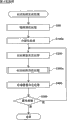
Figure 10 is the flow chart of expression according to the handling procedure of the dither matrix generation method of first embodiment of the invention.
Figure 11 is the key diagram of dither matrix M of the packetization process of expression implementation basis first embodiment of the invention.
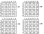
Figure 12 is 4 key diagrams of cutting apart matrix M 1~M4 of expression according to first embodiment of the invention.
Figure 13 is the key diagram that is illustrated in an example that becomes the evaluation of evaluation object matrix in the first embodiment of the invention.
Figure 14 is the flow chart of expression according to the handling procedure of the dither matrix evaluation processing of first embodiment of the invention.
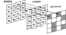
Figure 15 is the key diagram that expression point is formed on the situation at every place in 8 pixels, and these 8 pixels store the element that is easy to form threshold value a little corresponding to the 1st~8 of dither matrix M.
Figure 16 is that the matrix of status number value that expression will form dot pattern Dpa is the key diagram of the dot density matrix D da of quantificational expression dot density.
Figure 17 is the key diagram of expression four dot pattern Da1_2, Da2_3, Da3_4 and Da4_1, and these four dot patterns are formed on the 1st of dither matrix M~8th and store the printed pixels that belongs in the 1st~the 4th contiguous pixels group each in the element that is easy to form threshold value a little.
Figure 18 is expression and the key diagram of each corresponding dot density matrix D d1_2, Dd2_3, Dd3_4 and Dd4_1 among four dot pattern Da1_2, Da2_3, Da3_4 and the Da4_1.
Figure 19 is the flow chart of expression according to the handling procedure of the evaluation of estimate decision processing of first embodiment of the invention.
Figure 20 is the key diagram that expression is used for the calculating formula that the weighted addition of first embodiment of the invention handles.
Figure 21 is the key diagram of expression according to the flow chart of the error-diffusion method of second embodiment of the invention.
Figure 22 is the key diagram of expression Jarvice, Judice and Ninke type error diffusion matrix.
Figure 23 is the key diagram that expression is used for the continuous main scanning group of the error diffusion matrix M g1 of the error diffusion that the pixel groups under object pixel appends.
Figure 24 is the key diagram of flow chart of the variation of expression second embodiment of the invention.
Figure 25 is the key diagram that is illustrated in the error diffusion composite matrix Mg3 that uses in the variation of second embodiment of the invention.
Figure 26 is the flow chart of handling procedure of generation method of the dither matrix of expression third embodiment of the invention.
Figure 27 is the key diagram of the dither matrix M of the expression packetization process of implementing third embodiment of the invention.
Figure 28 is 4 key diagrams of cutting apart matrix M 1~M4 of expression third embodiment of the invention.
Figure 29 is the key diagram that is illustrated in an example of the dot pattern that becomes evaluation object in the third embodiment of the invention.
Figure 30 is the flow chart of the handling procedure handled of the dither matrix evaluation of expression third embodiment of the invention.
Figure 31 is the key diagram that expression point is formed on the situation at every place in 8 pixels, and these 8 pixels store the element that is easy to form threshold value a little corresponding to the 1st~8 of dither matrix M.
Figure 32 is that the matrix of status number value that expression will be formed with dot pattern Dpak is the key diagram of the dot density matrix D dak of quantificational expression dot density.
Figure 33 is the key diagram of the dot pattern Dp0ky of expression third embodiment of the invention.
Figure 34 is the key diagram of the dot density matrix D d0ky of expression third embodiment of the invention.
Figure 35 is the key diagram of the dot pattern Dp0k of expression third embodiment of the invention.
Figure 36 is the key diagram of the dot density matrix D d0k of expression third embodiment of the invention.
Figure 37 is the situation of storage candidate element is selected in expression from the element of cutting apart matrix M 1 a key diagram.
To be expression be formed on three dot density matrix D dak1, Dd0ky1 of status number value on the pixel corresponding with storing the candidate element (the 1st row the 3rd row) and the key diagram of Dd0k1 with point to Figure 38.
Figure 39 is the flow chart of expression according to the handling procedure of the dither matrix evaluation processing of third embodiment of the invention.
Figure 40 is the key diagram that expression is used for the calculating formula that the weighted addition of third embodiment of the invention handles.
Figure 41 is the flow chart of expression according to the handling procedure of the dither matrix evaluation processing of the variation of third embodiment of the invention.
Figure 42 is the key diagram that expression is used for the calculating formula that the weighted addition of the variation of third embodiment of the invention handles.
Figure 43 is the flow chart that the dither matrix of all fourth embodiment of the invention of expression generates the handling procedure of handling.
Figure 44 is the key diagram of content of the matrix shifting processing of expression fourth embodiment of the invention.
Figure 45 is the key diagram of the evaluation dot pattern Dp0kys1 of expression the 4th embodiment.
Figure 46 is the key diagram of the dot density matrix D d0kys1 of expression the 4th embodiment.
Figure 47 is the key diagram of an example of other using method of the single shared dither matrix Mc that generates of the generation method of expression the 4th embodiment.
Figure 48 is the key diagram of flow chart of the error-diffusion method of expression the 5th embodiment.
Figure 49 is the key diagram that expression is used for organizing to the pixel groups identical with object pixel the same main scanning group of the error diffusion matrix M g1 ' of propagated error ERgk, ERgy.
Figure 50 is the key diagram of flow chart of error-diffusion method of the variation of expression the 5th embodiment.
Figure 51 is the key diagram of the error diffusion composite matrix Mg3 that uses of the variation of expression the 5th embodiment.
Figure 52 is the key diagram of flow chart of the error-diffusion method of expression the 6th embodiment.
Figure 53 is the key diagram that expression is used for the same main scanning direction group of the error diffusion matrix of the error diffusion of appending to particular pixel group at the 6th embodiment.
Figure 54 is the key diagram that expression is used to calculate the low pass filter of the granular degree of RMS that first variation uses.
Figure 55 is the key diagram that expression is used to define the formula of the granular degree of RMS that first variation uses.
Figure 56 is the key diagram of expression by the formed printing state of line printer of second embodiment.
Figure 57 is that expression utilizes the some formation method of the 3rd variation to form the key diagram of the situation of printing image on printed medium.
Figure 58 is the key diagram of a plurality of pixel groups of expression the 3rd variation.
Figure 59 is the key diagram of a plurality of contiguous pixels groups of expression the 3rd variation.
Figure 60 is the key diagram of arrangement of nozzles below the print head of expression the 4th variation.
Among the figure: 10,12,251,252 ... print head, 20,200L ... color printer, 22 ... motor, 24 ... the balladeur train motor
25 ... roller, 30 ... balladeur train, 32 ... guidance panel, 40 ... control circuit,
56 ... connector, 60 ... printhead units, 90 ... computer, 91 ... video driver, 95 ... application program, 96 ... printer driver, 97 ... the resolution conversion assembly, 98 ... the look conversion assembly, 99 ... the assembly of losing lustre,
100 ... the printed data formation component, M ... dither matrix, M1 ... cut apart matrix, M2 ... cut apart matrix, M3 ... cut apart matrix, M4 ... cut apart matrix, EB1~EB4 ... element blocks, DP1, DP1a ... dot pattern, DP2, DP2a ... dot pattern, DP3, DP3a ... dot pattern, DP4, DP4a ... dot pattern.
Embodiment
Below, for effect of the present invention and effect more clearly are described, embodiments of the present invention are described in the following order.
A. the formation of the print system of the embodiment of the invention:
B. the idea of the optimization dither matrix of the embodiment of the invention:
C. utilize the improvement of the dispersiveness of the point that continuous main scanning forms
C-1. the halftoning of first embodiment (Ha one Off ト one Application) is handled (the generation method of dither matrix):
C-2. the halftone process of second embodiment (error-diffusion method):
D. the improvement of the dispersiveness of the polychrome point that forms with same main scanning
D-1. the halftone process of the 3rd embodiment (the generation method of dither matrix)
D-2. the halftone process of the 4th embodiment (the generation method of dither matrix)
D-3. the halftone process of the 5th embodiment (error-diffusion method)
D-4. the halftone process of the 6th embodiment (error-diffusion method)
E. variation
A: the formation of the print system of the embodiment of the invention:
Fig. 1 is the block diagram of formation of the print system of the expression embodiment of the invention.This print system comprises as the computer 90 of print control with as the color printer 20 of Printing Department.In addition, the combination of color printer 20 and computer 90 can be described as " printing equipment " of broad sense.
In the computer 90, application program 95 is worked under the scheduled operation system.Video driver 91 and printer driver 96 are assembled in the operating system, the printed data PD that is used to send to color printer 20 from application program 95 via its driver output.95 pairs of application programs handle that the image of object carries out being hoped processing, and via video driver 91 presentation video on CRT21.
The inside of printer driver 96 comprises the resolution conversion of input picture being the resolution conversion assembly 97 of printed resolution, the RGB look is transformed to the look conversion assembly 98 of CMYK, the assembly 99 of losing lustre that the dither matrix M that generates among the use aftermentioned embodiment is lost lustre to the output gray level number that can show the input gray level value by the formation of point, the utilization data that lose lustre generate the printed data formation component 100 of the printed data be used to send to color printer 20, the record counting rate meter DT that look conversion assembly 98 usefulness are showed signs of anger the look map table LUT of transform-based standard and handled the recording ratio of each size point of decision for losing lustre.Printer driver 96 is equivalent to realize generating the functional programs of printed data PD.The functional programs that is used for realizing printer driver 96 provides with the form of the recording medium that is recorded in embodied on computer readable.As this recording medium, for example, can utilize the various media of embodied on computer readable such as the memory internal device (memories such as RAM, ROM) of CD-ROM126, floppy disk, photomagneto disk, IC-card, boxlike ROM, punched card, the printed article that is printed with symbols such as bar code, computer and external memory.
Fig. 2 is the concise and to the point structural map of expression color printer 20.Color printer 20 comprises: utilize paper pushing motor 22 to carry the subscan drive division of printing P along sub scanning direction; Utilize balladeur train motor 24 to make balladeur train 30 axial (main scanning direction) reciprocating main scanning drive division along feeding-in roll 25; Driving is carried the printhead units 60 (being also referred to as the print head aggregate) on balladeur train 30 and is controlled the prepared Chinese ink ejection and put a driving mechanism that forms; And the control circuit 40 of managing paper pushing motor 22, balladeur train motor 24, having the printhead units 60 and the signal exchange between the guidance panel 32 of print head 10 and 20.Control circuit 40 is connected with computer 90 via connector 56.
Fig. 3 is that expression is positioned at the key diagram of arrangement of nozzles below print head 10 and 20.The yellow nozzle row Y that is formed with black nozzles row K, the cyan nozzle row C that is used to spray cyan (シ ア Application) prepared Chinese ink that is used to spray black prepared Chinese ink, magenta (マ ゼ Application タ) the nozzle rows Mz that is used to spray magenta prepared Chinese ink below the print head 10 and is used to spray yellow prepared Chinese ink.
A plurality of nozzle Nz of each nozzle rows arrange with certain nozzle pitch kD separately along sub scanning direction.Here, k is an integer, and D is the pitch (being called " some pitch ") suitable with the printed resolution of sub scanning direction.In this manual, we can say that also nozzle pitch is a k point.The point pitch of the unit here " point " finger mark brush resolution ratio.About the subscan feed, same " point " this unit that adopts.
In each nozzle Nz, be provided with the piezoelectric element (not shown), its as being used to drive each nozzle Nz so that during the printing of driving element of its ejection ink droplet, at print head 10 and 20 when main scanning direction MS moves, from each nozzle ejection ink droplet.
Have the color printer 20 that above-mentioned hardware constitutes, on one side can utilize paper pushing motor 22 to carry printing P, Yi Bian utilize balladeur train motor 24 that balladeur train 30 is moved back and forth.Simultaneously, carry out the ejection of ink droplet of all kinds, form large, medium and small ink dot, thereby on printing P, form vision system and color printer 20 most optimized image by the piezoelectric element that drives print head 10.Specifically, form the printing image as follows.In the following description, for understanding explanation easily, at first the single color printing example of print head 10 is only adopted in expression, then it is expanded to colored printing.
Fig. 4 is the key diagram of expression according to an example of the generation method of the single color printing image of the embodiment of the invention.In this image forming method example, while by carrying out main scanning and subscan, on printed medium, forming ink dot and generate the printing image.Main scanning is the action of instigating print head 10 to relatively move along main scanning direction with respect to printed medium.So-called subscan is the action of instigating print head 10 to relatively move along sub scanning direction with respect to printed medium.Print head 10 is constructed to ejection ink droplet on printed medium and forms ink dot.Print head 10 is equipped with 10 not shown nozzles with 2 times the interval of pel spacing k.
For the generation of printing image, Yi Bian carry out main scanning and subscan, Yi Bian carry out following steps.In the main scanning process of passage (pass) 1, be numbered location of pixels in 1,3,5,7,9,11,13,15,17 and 19 these 10 main scanning lines at wiregrating (ラ ス タ) and be numbered that ink dot forms on 1,3,5 and 7 the pixel.Main scanning line refers to the line that forms by along the continuous pixel of main scanning direction.Each circle is represented formation position a little.The pixel groups that numeral in each circle is made of a plurality of pixels that form ink dot simultaneously.In the passage 1, point is formed on the printed pixels that belongs to the 1st pixel groups.
In case the main scanning of passage 1 finishes, and just sends to the subscan of carrying out of 3 times of amount of movement Ls of pixel pitch along sub scanning direction.Generally, sending to by printed medium being moved carry out subscan, but in the present embodiment, for should be readily appreciated that explanation, also can be that print head 10 moves along sub scanning direction.In case end is sent in subscan to, just carry out the main scanning of passage 2.
In the main scanning process of passage 2, ink dot is formed on wiregrating and is numbered location of pixels in 6,8,10,12,14,16,18,20,22 and 24 these 10 main scanning lines and is numbered on 1,3,5 and 7 the pixel.Like this, in the passage 2, point is formed on the printed pixels that belongs to the 2nd pixel groups.In addition, diagram has been omitted wiregrating and has been numbered 22 and 24 these 2 main scanning lines.In case the main scanning of passage 2 finishes, and sends to aforementioned the same subscan with regard to carrying out, and carries out the main scanning of passage 3 then.
In the main scanning process of passage 3, ink dot is formed on the location of pixels that comprises in 10 main scanning lines that wiregrating is numbered 11,13,15,17 and 19 these several main scanning lines and is numbered on 2,4,6 and 8 the pixel.In the main scanning process of passage 4, ink dot is formed on the location of pixels that comprises in 10 main scanning lines that wiregrating is numbered 16,18 and 20 these 3 main scanning lines and is numbered on 2,4,6 and 8 the pixel.So as can be known, be numbered 15 later subscan positions at wiregrating and can form gapless ink dot.In passage 3 and the passage 4, point is respectively formed on the printed pixels that belongs to the 3rd pixel groups and the 4th pixel groups.
Observe the generation of this printing image if be conceived to certain zone, be appreciated that then it is following carrying out.For example, if with wiregrating be numbered 15~19 and location of pixels to be numbered 1~8 zone be the target area, then be appreciated that in this target area, to form the printing image as follows.
As can be known, in passage 1, in the target area, be formed be formed on wiregrating be numbered 1~5 and location of pixels be numbered the identical pattern of ink dot of 1~8 location of pixels.This dot pattern is formed by the point that is formed on the pixel that belongs to the 1st pixel groups.That is to say,, in the target area, on the pixel that belongs to the 1st pixel groups, form a little 1 li of passage.
In passage 2, in the target area, on the pixel that belongs to the 2nd pixel groups, form a little.In passage 3, in the target area, on the pixel that belongs to the 3rd pixel groups, form a little.In passage 4, in the target area, on the pixel that belongs to the 4th pixel groups, form a little.
Like this, as can be known, in the single color printing process of present embodiment, by make belong in the 1st~more than the 4th pixel groups each printed pixels in common printing zone mutually combination form the printing image.
On the other hand, in the colored printing process of present embodiment,, and form color printing image by on from print head (Fig. 3) ejection C, Mz, Y and K prepared Chinese ink to the 1 of all kinds~more than the 4th pixel groups each.Like this, in the colored printing process, utilize each main scanning almost side by side to spray polychrome prepared Chinese ink.
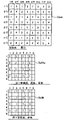
Fig. 5 represents in embodiments of the present invention each the printed pixels combination and generate the key diagram of the situation of printing image on printed medium mutually in common printing zone that belongs to a plurality of pixel groups by making.In Fig. 5 example, the printing image is the printing image with predetermined middle gray (monochrome).Dot pattern DP1 and DP1a represent to be formed on the dot pattern on a plurality of pixels that belong to the 1st pixel groups.Dot pattern DP2 and DP2a represent to be formed on the dot pattern on a plurality of pixels that belong to the 1st and the 2nd pixel groups.Dot pattern DP3 and DP3a represent to be formed on the dot pattern on a plurality of pixels that belong to the 1st~the 3rd pixel groups.Dot pattern DP4 and DP4a represent to be formed on the dot pattern on a plurality of pixels that belong to all pixel groups.
Dot pattern DP1, DP2, DP3 and DP4 are the dot patterns under the situation of the dither matrix that uses prior art.Dot pattern DP1a, DP2a, DP3a and DP4a are the dot patterns under the situation of using dither matrix of the present invention.As can understanding from Fig. 5, under the situation of using dither matrix of the present invention, particularly in the overlapping less dot pattern DP1a and DP2a of dot pattern, the situation of the existing dither matrix of the dispersed ratio use of point is homogeneous more.
In the dither matrix of prior art,, therefore only be conceived to the dispersiveness of the point in the final printing image that forms (being dot pattern DP4 in the example of Fig. 5), and carry out optimization because there is not the notion of so-called pixel groups.
Yet the inventor dare to be conceived to the dot pattern in a little the forming process and the picture element that prints image is resolved.As can be known, this analysis result is to produce the irregular of image owing to the density of putting dot pattern in the forming process causes.Irregular for this image, the inventor finds, because the overlap mode of the polychrome point that forms in same main scanning is inconsistent, separates the part of oozing of not spreading and sinking in polychrome point owing to color spot appears in generation spot shape so polychrome point contacts the part of oozing of spreading and sinking in.
This color spot also appears under the situation of utilizing 1 scanning formation printing image.Yet although color spot appears on the whole printing image equably, human eyes are difficult to see.Because the cause that homogeneous occurs, prepared Chinese ink does not take place and spreads and sinks in and ooze in the uneven one spot that contains low-frequency component.
Yet, when in same main scanning, almost forming simultaneously in the dot pattern that forms in the pixel groups of ink dot, because prepared Chinese ink is spread and sunk in and oozed and when human eyes are easy to cognitive low frequency region and color spot occurs, descend and obviousization that become as significant picture element.So, the inventor finds first, forms in the formation by ink dot under the situation of printing image, also is conceived to almost forming the dot pattern that forms in the pixel groups of ink dot simultaneously the dither matrix optimization, and is relevant with high picture elementization.
In addition, the inventor found out also that not only prepared Chinese ink is spread and sunk in and oozed, the prepared Chinese ink physical phenomenon of prepared Chinese ink aggegation spot, gloss uneven and so-called bronze (Block ロ Application ズ) phenomenon also as the deterioration of picture element by the perception significantly of the mankind's eyes.The bronze phenomenon is because the aggegation of the dyestuff of ink droplet etc., and causes print surface to present the phenomenon that the state of the light that bronze colour etc. reflected by the printing surface changes because of viewing angle.In addition, the inventor has found out that this prepared Chinese ink physical phenomenon also occurs in continuous sweep (for example passage 1 and passage 2).In addition, the inventor has found out that also above-mentioned color spot also takes place in continuous sweep.
In addition, for existing dither matrix, be prerequisite by closing with the mutual alignment that presupposes each pixel groups, seek optimization, concern in the mutual alignment can not guarantee optimality under nonsynchronous situation, thereby become the reason that picture element significantly descends.Yet the present inventor utilizes experiment to confirm for the first time: according to dither matrix of the present invention, even if also can guarantee a little dispersiveness in the dot pattern of each pixel groups, therefore also can misplace with respect to the mutual alignment relation and guarantee high-stability.
In addition, the inventor finds out also that this technological thought is accompanied by the high speed of print speed printing speed and is more and more important.Because the high speed of print speed printing speed is relevant with following situation: promptly, formed the point of next pixel groups can not fully keeping the prepared Chinese ink absorption with in the time.
B. the idea of the optimization dither matrix in the embodiment of the invention:
Fig. 6 is the key diagram of the part of illustration dither matrix conceptually.In illustrated matrix, the threshold value of do not have to omit selecting from the scope of gray scale 1~255 is stored, at 128 elements of transverse direction (main scanning direction) and 64 elements of longitudinal direction (sub scanning direction) in totally 8192 elements.In addition, the size of dither matrix is not limited to as illustrative size among Fig. 6, but can also comprise matrix that number of elements in length and breadth equates at interior all size.
Fig. 7 is that expression uses the point of dither matrix to form the key diagram of the idea that has or not.For illustrated convenience, only represented a part of element.When commit point formation has or not, as shown in Figure 7, with the gray value and the threshold that is stored in the corresponding position of dither matrix of view data.Form a little than being stored under the big situation of threshold value in the dither table gray value one side of view data, and under the less situation of gray value one side of view data, do not form a little.In Fig. 7, the pixel that has shade means becomes a formation object pixels.Like this, if adopt dither matrix, the gray value by the movement images data be set in this simple process that the threshold value in the dither matrix compares, the point that can judge each pixel forms and has or not, thereby can promptly implement greyscale transform process.In addition, as can be known, if determined the gray scale of view data, then can determine whether in each pixel, to have formed point by the threshold value that is set in the dither matrix fully, in organizing dithering, can come the generation situation at control point energetically by being set in the memory location of the threshold value in the dither matrix.
Like this, organize dithering, can come the generation situation at control point energetically, therefore have the feature that to come dispersiveness picture element in addition in control point by the memory location of adjusting threshold value by being set in the memory location of the threshold value in the dither matrix.This means that the optimal treatment that can utilize dither matrix makes halftone process with respect to various dbjective state optimization.
Fig. 8 is the illustration key diagram that has the spatial frequency characteristic of preset threshold in each pixel of blue noise dither matrix of blue noise characteristic as the simple example of the adjustment of dither matrix conceptually.The spatial frequency characteristic of blue noise matrix is that near the higher-frequency zone of one-period length one-period, length was 2 pixels has the characteristic of peak frequency composition.This spatial frequency characteristic has been considered the human vision property setting.That is to say that the blue noise matrix is a human vision property of having considered that in high-frequency region sensitivity is lower, adjust the dither matrix of the memory location of threshold value in the mode that produces the peak frequency composition at high-frequency region.
In addition, in Fig. 8, with the spatial frequency characteristic of green noise matrix as imaginary curve and illustration.As shown in the figure, the spatial frequency characteristic of green noise matrix is that one-period length has the peak frequency composition in the intermediate frequency zone from the 2nd pixel to the dozens of pixel.Threshold value for green noise matrix, because being set to, green noise matrix has such spatial frequency characteristic, therefore if judge the having or not of formation of each pixel with reference to having the dither matrix of green noise characteristic, then form point with several units adjacency on one side, Yi Bian the state that disperses with the group variety of putting (Gu ま り) forms as a whole.As so-called laser printer etc., be difficult to stably form in the printer of the fine point about a pixel, what the green noise matrix by generation like this came that judging point forms has or not, and can suppress the generation of isolated point.As a result, can promptly export the stable image of picture element.Utilizing laser printer etc. and in the dither matrix that has or not time institute's reference of the formation of judging point, setting adjusted threshold value conversely speaking, in mode with green noise characteristic.
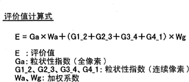
Fig. 9 (a) be conceptually represent vision spatial frequency characteristic VTF (vision transfer function) promptly at the key diagram of the sensory characteristic of the spatial frequency of the vision that the mankind had.If utilize the spatial frequency characteristic VTF of vision, then can by human visual sensitivity as this transfer function of spatial frequency characteristic VTF of so-called vision and modelling, the point after the halftone process is resorted to the granular sense quantification of human vision.So and the value after the quantification is called the graininess index.Fig. 9 (b) expression is used to express the representative empirical formula of the spatial frequency characteristic VTF of vision.Fig. 9 (c) is the formula of definition graininess index.COEFFICIENT K among Fig. 9 (c) is to be used for the coefficient of the value that obtains with the mankind's sensation merging.
About this quantification that resorts to the granular sense of human vision, can make dither matrix with respect to human visual system's optimization accurately.Particularly, the graininess index that obtains in the following way can be utilized as the evaluation function of dither matrix: promptly the dot pattern of setting when each input gray level value of input in dither matrix is carried out Fourier transformation and tries to achieve power spectrum FS, and after the spatial frequency characteristic VTF with vision multiplies each other, carry out integration (Fig. 9 (c)) with full input gray level value.In this example, if, then can realize optimization so that the mode that the evaluation function of dither matrix diminishes is adjusted the memory location of threshold value.
C. in the improvement of the dispersiveness of the point of main scanning formation continuously
C-1. the halftone process of first embodiment (the generation method of dither matrix)
Halftone process according to first embodiment of the invention realizes by the dither matrix M that use utilizes following method to generate.
Figure 10 is the flow chart of handling procedure of the dither matrix generation method of expression first embodiment of the invention.In the generation method of first embodiment, be constituted as, can consider that the dispersiveness of the point that forms by continuous main scanning (パ ス) realizes optimization in the forming process of printing image.In this example,, generate the little dither matrix of 8 row, 8 row for should be readily appreciated that explanation.The suitableeest property of dither matrix is estimated as performance, used graininess index (Fig. 9 (c)).
In step S100, carry out packetization process.So-called packetization process, in the present embodiment, be meant following such processing: promptly in the forming process (Fig. 4) of printing image, dither matrix is divided into and each the corresponding element of a plurality of pixel groups that almost forms point simultaneously, and continuously the group that has formed point is synthesized in time.
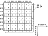
Figure 11 is the key diagram of dither matrix M that the packetization process of first embodiment of the invention is carried out in expression.In this packetization process, be divided into 4 pixel groups among Fig. 4.Be recorded in the affiliated pixel groups of each element of numeral of each element of dither matrix M.For example, the element of the 1st row the 1st row belongs to the 1st pixel groups (Fig. 4), and the element of the 2nd row the 1st row belongs to the 2nd pixel groups.
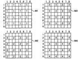
Figure 12 is 4 key diagrams of cutting apart matrix M 1~M4 of expression according to first embodiment of the invention.Cut apart matrix M 1 by with the element of dither matrix M in a plurality of elements of belonging to the corresponding a plurality of elements of pixel of the 1st pixel groups and becoming the sky hurdle be that empty hurdle element constitutes.Empty hurdle element is not limited to the input gray level value, does not normally form the element of point.Cut apart matrix M 2~M4 respectively by with the element of dither matrix M in belong to the pixel of the 2nd~the 4th pixel groups corresponding a plurality of elements and empty hurdle element and constitute.
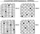
For such generation cut apart matrix M 2~M4, the point of formation continuous in time is synthetic, thus generate corresponding to each evaluation matrix M 1_2, M2_3, M3_4 and the M4_1 (Figure 13) in the 1st~the 4th contiguous pixels group.
Figure 13 is the key diagram that is illustrated in an example that becomes the evaluation of evaluation object matrix in the first embodiment of the invention.In the figure, the dot pattern that is formed in the 1st~the 4th contiguous pixels group corresponding with each evaluation matrix becomes evaluation object.The 1st contiguous pixels group is the 1st pixel groups and the synthetic pixel groups of the 2nd pixel groups that forms continuously in passage 1 and passage 2 respectively.Same, the 2nd contiguous pixels group is with the 2nd pixel groups and the synthetic pixel groups of the 3rd pixel groups.The 3rd contiguous pixels group is with the 3rd pixel groups and the synthetic pixel groups of the 4th pixel groups.The 4th contiguous pixels group is with the 4th pixel groups and the synthetic pixel groups of the 1st pixel groups.
Thus, in first embodiment, synthetic dot pattern is evaluated, described synthetic dot pattern is to constitute by the dot pattern that is formed respectively by continuous main scanning is merged, so as described later, can be conceived to utilize the dispersiveness of the dot pattern as a whole that continuous main scanning forms, the optimization of seeking dither matrix.
The dispersiveness that is conceived to synthetic dot image realizes that the optimization of dither matrix is mainly based on following two reasons.First, the prepared Chinese ink physical phenomenon of prepared Chinese ink aggegation spot, luster mottlings and so-called bronze phenomenon, as previously mentioned (for example in continuous main scanning, passage 1 among Fig. 4 and passage 2) in also take place, be related to high picture elementization so the dispersiveness of the dot image that forms main scanning both sides continuously is optimized.The second, suppress the some formation time caused picture element deterioration of deviation at interval that produces owing to the difference (for example, main scanning left end A among Fig. 2 and main scanning right-hand member B) of main scanning position.
The deviation in this time interval is followingly to produce like that.For example consider such a case: promptly printhead units 60 (Fig. 2) is promptly forming point from main scanning left end A along going to direction when main scanning right-hand member B carries out main scanning, and this printhead units 60 promptly forms point from main scanning right-hand member B along Return-ing direction when main scanning left end A carries out main scanning thereafter.In the case, in the direction main scanning, printhead units 60 after the main scanning left end A place as the starting point of going to the direction main scanning forms point through for example 0.5 second at main scanning right-hand member B place formation point as the terminating point of going to the direction main scanning.Then, if through for example beginning the Return-ing direction main scanning after 0.1 second, then after the main scanning right-hand member B place as the starting point of returning the direction main scanning forms point, through for example after 0.5 second at main scanning left end A place formation point as the terminating point that returns the direction main scanning.In the case, main scanning left end A place, the time interval that point forms is 1.1 seconds (=0.5 second+0.5 second+0.1 second).On the other hand, at B place, main scanning right side, the time interval that point forms is 0.1 second.
Thus, the interval that main scanning left end A sentenced 1.1 seconds forms point and sentences 0.1 second interval formation point at main scanning right-hand member B, the dispersion so the degree that main scanning left end A and main scanning right-hand member B place prepared Chinese ink physical phenomenon take place becomes.As previously mentioned, if the prepared Chinese ink physical phenomenon takes place on whole printing image equably, then the decline of picture element is difficult to appeal to human vision, can improve by proofreading and correct.Yet discrete (perhaps uneven) of prepared Chinese ink physical phenomenon can resort to the sensation of human vision significantly as the deterioration of picture element.In the present embodiment, for suppressing this fluctuation, optimization dither matrix M is to improve the dispersiveness of the dot pattern that both sides form in continuous main scanning.
Like this, in case the packetization process of step S100 (Figure 10) finishes, handle just entering step S200.
At step S200, carry out the targets threshold decision and handle.It is the processing that the threshold value that becomes storage element is determined that so-called targets threshold decision is handled.In the present embodiment, select to decide threshold value by the threshold value that promptly is easy to form value a little from the threshold value of smaller value in order.Like this, if select from the threshold value that is easy to form a little in order, then because to be arranged in a graininess significantly the threshold value controlled of the some configuration of highlight regions locate the element that will store in order, so can provide bigger design freedom to putting the significant highlight regions of graininess.As described later, after having determined, 8 threshold values determine the 9th threshold value in this example.
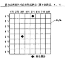
Figure 14 is the flow chart of the handling procedure handled of the dither matrix evaluation of expression first embodiment of the invention.In step S310, the corresponding points of decision threshold are put ON.What is called is decision threshold, is meant the threshold value that storage element has been determined.In the present embodiment,, therefore, on the pixel corresponding, must form a little with the element that stores fixed threshold value when when targets threshold formation is put owing to selects in order from the threshold value that is easy to form point value as previously mentioned.On the contrary, the targets threshold place has formed the minimum input gray level value place of point, does not form a little on the pixel corresponding with element beyond the element that stores decision threshold.
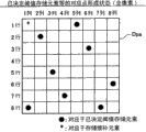
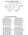
Figure 15 is the key diagram that the expression point is formed on the situation at 8 each places in the pixel, and described 8 pixels are corresponding to storing the element that is easy to the formation threshold value in the 1st of dither matrix M~8.The dot pattern Dpa of Gou Chenging is used to determine to be formed on which pixel place at the 9th like this.* the candidate element is stored in number expression.
At step S320 (Figure 14), store the candidate element and select to handle.So-called storage candidate element is selected to handle, and is the processing of storage candidate element of candidate that is selected to the storage element of threshold value from being used as the evaluation matrix the selecteed element of cutting apart matrix M 1.In this example, be with the storage element of * number first row, first row to be selected as storing the candidate element.
The selection of storage candidate element for example can be selected to remove conduct according to priority and determine to be i.e. all other storage element the decision element of 8 storage elements of the storage element of the threshold value of dither matrix M, perhaps, can preferentially select this as long as exist not and the adjacent element of decision element.
In step S330 (Figure 14), suppose at selected storage candidate element place point and put ON.Thus, can carry out the evaluation of dither matrix M, described dither matrix M is the dither matrix when the 9th threshold value that is easy to form a little is stored in the candidate key element.
Figure 16 is to be the key diagram that the dot density matrix D da of quantificational expression dot density represents to the matrix after will having formed state behind the dot pattern Dpa and quantizing.Numeral 0 do not mean and forms a little, and numeral 1 means and forms point (comprising the situation that supposition forms point).
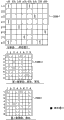
Figure 17 is the key diagram that expression is formed at four dot pattern Dp1_2, Dp2_3, Dp3_4 and the Dp4_1 at following such printed pixels place: promptly belong to the 1st~No. 8 of storing at dither matrix M and locate to form easily in the 1st~the 4th contiguous pixels group in the element of threshold value of point each.In other words, from dot pattern Dpa (Figure 15), pick out and be formed with each the dot pattern of printed pixels that belongs in the 1st~the 4th contiguous pixels group.Figure 17 is the same with dot pattern Dpa (Figure 15), utilizes * number expression and the corresponding printed pixels of storage candidate element.Figure 18 is expression and the key diagram of each corresponding dot density matrix D d1_2, Dd2_3, Dd3_4 and Dd4_1 among four dot pattern Da1_2, Da2_3, Da3_4 and the Da4_1.
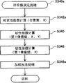
After determining 5 dot density matrix D da, Dd1_2, Dd2_3, Dd3_4 and Dd4_1 like this, handle entering into evaluation of estimate decision processing (step S340).
Figure 19 is the flow chart of expression according to the handling procedure of the evaluation of estimate decision processing of first embodiment of the invention.At step S342, with whole pixels as evaluation calculation and object graininess index.Specifically, based on dot density matrix D da (Figure 16) and utilize the formula of Fig. 9 (c) to calculate the graininess index.In step S344, with the 1st~the 4th contiguous pixels group as evaluation calculation and object graininess index.Specifically, based on each (Figure 18) among dot density matrix D da, Dd1_2, Dd2_3, Dd3_4 and the Dd4_1 and utilize the formula of Fig. 9 (c) to calculate the graininess index equally.
At step S348, be weighted (heavy body is paid け) addition process.It is that in each graininess index of being calculated each is weighted the processing of addition that weighted addition is handled.
Figure 20 is the key diagram that expression is used for the calculating formula of weighted addition processing.As calculating formula since then is understandable, evaluation of estimate E be confirmed as following such two values with the value that promptly on the graininess index Ga of relevant both full-pixel (in step S342, calculating), multiply by weight coefficient Wa (for example 4); And the value that on each 4 graininess index G1_2, G2_3, G3_4, G4_1 (S344 calculates in step) sum of relevant the 1st~the 4th contiguous pixels group, multiply by weight coefficient Wg (for example 1).
For whole storage candidate elements, carry out a series of processing (Figure 14) (step S350) of this decision processing (step S340) from storage candidate element selection processing (step S320) to evaluation of estimate.Like this, if all storage candidate elements have been determined evaluation of estimate separately, then handle and enter into step S400 (Figure 10).
In step S400, carry out the storage element decision and handle.In the storage element decision is handled, the storage candidate element of evaluation of estimate minimum is determined as the storage element for targets threshold.
This processing (step S200~step S400) repeatedly changes threshold value until final threshold value (step S500).Final threshold value can be the max-thresholds that is difficult to most form a little, perhaps can be the max-thresholds in the predefined predetermined threshold range.This is at first as the threshold value of evaluation object too.
Like this, in first embodiment, with dither matrix M optimization so that the graininess index that merges the synthetic dot pattern that constitutes by a plurality of dot patterns that will be in continuous main scanning form is respectively diminished, therefore can suppress because the picture element that the prepared Chinese ink physical phenomenon that takes place each other at a plurality of dot patterns causes descends, described a plurality of dot patterns are formation respectively in the continuous in time main scanning.In addition, in bidrectional printing, the discrete caused picture element decline in the time interval that the points that can also suppress to produce owing to the main scanning position is different significantly form.
C-2. the halftone process of second embodiment (error-diffusion method)
Figure 21 is the key diagram of flow chart of the error-diffusion method of expression second embodiment of the invention.This embodiment gives by the original characteristic of following such processing and utilizing error-diffusion method and is formed with the dot pattern that belongs to each printed pixels in the contiguous pixels group good dispersiveness is provided, and this processing is also spread another kind of error to the contiguous pixels group except common error diffusion.In error-diffusion method, make as constituting some formation and judge the some formation state that the object pixel of object pixels is shifted one by one and decides whole printed pixels.Displacement method generally is following such method: for example make object pixel one by one along the main scanning direction displacement, if the processing of whole pixels of this main scanning line finishes, make object pixel be displaced to the adjacent main scanning line that is untreated then.
In step S900, read in the propagated error that spreads at object pixel from other a plurality of pixels of having handled.In the present embodiment, propagated error comprises whole propagated error ERa and group propagated error ERg.
Whole propagated error ERa adopts error diffusion global matrix Ma shown in Figure 22 and the error that spreads.In the present embodiment, error is used known Jarvice, Judice﹠amp; Ninke type error diffusion matrix and spreading.This error diffusion is carried out as general error diffusion.The same with the error-diffusion method of prior art, as the original characteristic of error-diffusion method, good dispersiveness is provided can for final dot pattern.
But, in the present embodiment, this error-diffusion method is different from existing error-diffusion method part and is: in order further to provide good dispersiveness for being formed on the point group that utilizes on the pixel that continuous main scanning mutually forms, and group propagated error Erg is appended diffusion.
Figure 23 is that expression is used for key diagram error diffusion, the continuous main scanning group of error diffusion matrix M g1 that the pixel groups under object pixel is appended.The continuous main scanning group of error diffusion matrix M g1 is constructed such that error only is diffused into the mutual continuous formed pixel of main scanning.This error diffusion can easily realize by constituting according to the mode that makes error not diffuse into the pixel that forms in mutual discontinuous main scanning.
In the present embodiment, the continuous main scanning group of error diffusion matrix M g1 utilizes following relation to realize.
The point of (1) the 1st pixel groups and the 3rd pixel groups is also discontinuous and form.The point of (2) the 2nd pixel groups and the 4th pixel groups is also discontinuous and form.Position relation between (3) the 1st pixel groups and the 3rd pixel groups concerns the same with the position between the 2nd pixel groups and the 4th pixel groups.
For example, belong at object pixel under the situation of the 1st pixel groups, error diffusion is not constituted the continuous main scanning group of error diffusion matrix M g1 to the mode of the pixel that belongs to the 3rd pixel groups.That is, make the element blank that belongs to the location of pixels of the 3rd pixel groups with respect to the 1st pixel groups, and this element is assigned to other pixel.Belong at object pixel under the situation of the 3rd pixel groups,, can utilize the continuous main scanning group of error diffusion matrix M g1 like this because the relation of the position between the 1st pixel groups and the 3rd pixel groups is relative (object な).Then, belong at object pixel under the situation of the 2nd pixel groups, because it is the same that the position between the 2nd pixel groups and the 4th pixel groups relation and position between the 1st pixel groups and the 3rd pixel groups concern, so also can utilize the continuous main scanning group of error diffusion matrix M g1 in the case like this.In addition, belong at object pixel under the situation of the 4th pixel groups, also, can utilize the continuous main scanning group of error diffusion matrix M g1 like this because it is relative (object な) that the position between the 2nd pixel groups and the 4th pixel groups concerns.Like this, no matter which pixel groups object pixel belongs to, and can utilize the continuous main scanning group of error diffusion matrix M g1.
Like this, in the present embodiment, as follows error is spread: promptly make the maximal end point pattern have predetermined characteristics, and make in the characteristic that has regulation by the dot pattern that forms on the mutual continuously formed pixel of main scanning by means of error diffusion based on the continuous main scanning group of error diffusion matrix M g1 by means of error diffusion based on error diffusion global matrix Ma.
In step S910, calculate the average diffusion error E Rave of the weighted average of propagated error ERa as a whole and group propagated error ERg.In the present embodiment, as an example, the weight coefficient of whole propagated error ERa and group propagated error ERg is respectively " 4 " and " 1 ".With average diffusion error E Rave, as the value that multiply by weight coefficient " 4 " on the whole propagated error ERa and the value that on group propagated error ERg, multiply by weight coefficient " 1 " and divided by the value of the summation " 5 " of weight coefficient, and calculate.
In step S920,, proofread and correct data Dc and calculate input gray level Dt and average propagated error ERave addition.
In step S930, correction data Dc and the pre-set threshold Thre that is calculated compared.For proofreading and correct under the data Dc situation bigger than threshold value Thre, decision forms point (step S940) at comparative result.On the other hand, proofreading and correct under the data Dc situation littler than threshold value Thre, decision does not form point (step S950).
In step S960, calculate gamma error, simultaneously this gamma error is diffused into untreated pixel on every side.Gamma error is to proofread and correct data Dc and the decision that has or not by means of a formation and poor between the actual grey value that generates.For example, be 223 and to utilize point to form an actual gray scale that generates be 255 if proofread and correct the gray scale of data Dc, then gamma error be-32 (=223-255).In this step (S960), error diffusion is utilized error diffusion global matrix Ma and is carried out.
Specifically, right adjacent pixel about object pixel, to the value of the gamma error-32 that generated by object pixel, the value " 224/48 " (=-32 * 7/48) of the coefficient 7/48 corresponding with the right adjacent pixel of this object pixel is multiply by among the error diffusion global matrix Ma in diffusion.In addition, about second (2 つ) of object pixel right adjacent pixel, the value-160/48 (=-32 * 5/48) with the right adjacent corresponding coefficient 5/48 of pixel of second of this object pixel is multiply by among the error diffusion global matrix Ma in diffusion.The same with existing error-diffusion method, as the original characteristic of error-diffusion method, this error diffusion makes the maximal end point pattern have predetermined characteristics.
At step S970, different with existing error diffusion, utilize the error diffusion of the continuous main scanning group of error diffusion matrix M g1 (Figure 23) with appending.As previously mentioned, this is to provide good dispersiveness for the dot pattern that the pixel that forms in utilizing mutually main scanning is continuously formed.
Specifically, about the pixel on object pixel the right, for the value of the gamma error-32 that is generated by object pixel, the value 0 (=-32 * 0) of coefficient 0 corresponding with right neighbour's pixel among the continuous main scanning group of the error diffusion matrix M g1 is multiply by in diffusion.In addition, for the gamma error-32 that is generated by object pixel, the value-20/3 (=-32 * 5/24) that multiply by with the corresponding coefficient 5/24 of this object pixel pixel adjacent with the object pixel downside among the continuous main scanning group of the error diffusion matrix M g1 is multiply by in diffusion.
Like this, in the error-diffusion method of second embodiment, utilize the error diffusion of appending to the contiguous pixels group, can realize the purpose of first embodiment from object pixel.
Figure 24 is the key diagram of flow chart of the variation of expression second embodiment of the invention.Present embodiment is different from the second embodiment part and is to replace three step S900 of second embodiment and delete these other two step S910 and S970 with step S900b.On the other hand, if compare with existing error diffusion, the error diffusion matrix difference used of error diffusion only.Present embodiment is used to utilize linear property expansion second embodiment of propagated error, and the content of processing is equal to second embodiment on mathematics.
In step S900b, read in the average diffusion error E Rave that utilizes error diffusion composite matrix Mg3 diffusion.Average diffusion error E Rave is identical with the value that step S910a at second embodiment calculates.Error diffusion composite matrix Mg3 utilizes predetermined weight coefficient resultant error diffusion global matrix Ma and the continuous main scanning group of error diffusion matrix M g1 and the error diffusion matrix that constitutes.Predetermined weight coefficient is 4 pairs 1 in order.
Error diffusion composite matrix Mg3 (Figure 25) is by the denominator of each coefficient of error diffusion global matrix Ma and the continuous main scanning group of the adjusted error diffusion of weighting matrix M g1a and the molecule matrix that constitutes of addition simply.For the continuous main scanning group of the adjusted error diffusion of weighting matrix M g1a,, the denominator and the molecule of each coefficient of the continuous main scanning group of error diffusion matrix M g1 be multiply by 1.5 in order to carry out this addition.Thus, because the summation of the molecule of error diffusion global matrix Ma be 48 and the summation of the molecule of the continuous main scanning group of the adjusted error diffusion of weighting matrix M g1a be 12, so about molecule summation ratio, according to error diffusion global matrix Ma and the continuous main scanning group of error diffusion matrix M g1a, be 4 to 1.On the other hand, by the denominator that makes each coefficient be 60 (=48+12), the coefficient summation that can be propagated error is 1.In addition, in error diffusion composite matrix Mg3, be integer in order to make molecule, making denominator is 120.
Present embodiment has following advantage: promptly can in the processing procedure identical, only be suitable for the present invention by replacing error diffusion matrix with existing error diffusion, and because once carry out a plurality of DIFFUSION TREATMENT, so it is little to handle burden.
D. the improvement of the dispersiveness of the polychrome point that in same main scanning, forms
D-1. the halftone process of the 3rd embodiment (the generation method of dither matrix)
The halftone process of third embodiment of the invention realizes by the dither matrix M that use utilizes following method to generate.
Figure 26 is the flow chart of handling procedure of the dither matrix generation method of expression third embodiment of the invention.The dither matrix generation method part that this embodiment is different from first embodiment is: packetization process (step S100) and dither matrix evaluation are handled (step S300) and are changed to step S100a and step S300a respectively, have appended mass colour/matrix and have selected to handle and reprocessing (step S250 and S450).
The packetization process of present embodiment (step S100a), different with first embodiment, it is that dither matrix M is divided into each and prints the corresponding element of a plurality of pixel groups that almost forms point in the image forming course (Fig. 4) simultaneously.
Figure 27 is the key diagram of the dither matrix M of the expression packetization process of implementing third embodiment of the invention.In this packetization process, be divided into four pixel groups among Fig. 4.Be recorded in the numeral of each element of dither matrix M, represent the pixel groups that each element is affiliated.For example, the element of the 1st row the 1st row belongs to the 1st pixel groups (Fig. 4), and the element of the 2nd row the 1st row belongs to the 2nd pixel groups, and this point is the same with first embodiment.Dither matrix M is by constituting with the yellow matrix M y of dither matrix and the black prepared Chinese ink black matrix" Mk with dither matrix as yellow prepared Chinese ink.
Figure 28 is 4 key diagrams of cutting apart matrix M 1~M4 of expression according to third embodiment of the invention.Cut apart matrix M 1, same with first embodiment, be that empty hurdle element constitutes by a plurality of elements corresponding in the element of dither matrix M with a plurality of elements that become the sky hurdle with the pixel that belongs to the 1st pixel groups.Empty hurdle element is and the irrelevant and common element that does not form a little of input gray level.Cut apart matrix M 2~M4 respectively by with the element of dither matrix M in belong to the pixel of the 2nd~the 4th pixel groups corresponding a plurality of elements and empty hurdle element and constitute.
Mass colour/matrix is selected to handle (step S250) and is selected mass colour and the processing of the dither matrix of mass colour correspondence therewith.In this example, as previously mentioned,, utilize black prepared Chinese ink and yellow prepared Chinese ink to print in order to should be readily appreciated that explanation.Here, select the black matrix" of black prepared Chinese ink and the conduct dither matrix corresponding with black prepared Chinese ink.
Figure 29 is the key diagram that is illustrated in an example of the dot pattern that becomes evaluation object in the third embodiment of the invention.This figure is illustrated in three dot patterns that become evaluation object under the situation of selecting the 1st pixel groups, black prepared Chinese ink and the black matrix" corresponding with cutting apart matrix M 1.First dot pattern is the both full-pixel black pattern Dpak that utilizes all black color dots to constitute.Second dot pattern is the 1st pixel groups colour mixture pattern Dp0ky that utilizes black color dots with the yellow dots will formation of the printed pixels formation that belongs to the 1st pixel groups of the printed pixels formation that belongs to the 1st pixel groups.Thirdly pattern is the first pixel groups black pattern Dp0k that utilizes the black color dots formation of the printed pixels formation that belongs to the 1st pixel groups.
(step S300a) handled in the dither matrix evaluation of the 3rd embodiment, be with the different part of first embodiment, seek optimization for the dispersiveness of the polychrome point considering in the printing image forming course, almost to form simultaneously, be conceived to utilize the graininess index of the dot pattern of polychrome point formation to estimate dither matrix.For this reason, step S330 and step S340 are changed to step S330a and step S340a respectively.
Figure 30 is the flow chart of expression according to the handling procedure of the dither matrix evaluation processing of third embodiment of the invention.In step S310, the same with first embodiment, the corresponding points of decision threshold are put ON.
Figure 31 is illustrated in the key diagram that each place in 8 pixels forms the situation of point, and to locate to be easy to form the element of threshold value a little corresponding with storing at dither matrix M the 1st~No. 8 for described 8 pixels.The dot pattern Dpak of Gou Chenging is used to determine to be formed on which pixel at the 9th like this.
Figure 32 is that the matrix of status number value that expression will form dot pattern Dpak is the key diagram of the dot density matrix D dak of quantificational expression dot density.Numeral 0 do not mean and forms a little, and numeral 1 means and formed point.
Figure 33 and Figure 34 are the key diagrams of expression dot pattern Dp0ky and the dot density matrix D d0ky corresponding with it.Dot pattern Dp0ky is made of black color dots and yellow dots will.Black color dots is formed in and stores easily at black matrix" the 1st~No. 8 and locates to be easy to form in corresponding 8 printed pixels of element of threshold value and the point of cutting apart on matrix M 1 corresponding each printed pixels.Yellow dots will is formed in and stores easily at yellow matrix the 1st~No. 8 and locates to form the point that belongs in corresponding 8 printed pixels of element of threshold value on each printed pixels of cutting apart matrix M 1.
Figure 35 and Figure 36 are the key diagrams of expression dot pattern Dp0k and the dot density matrix D d0k corresponding with it.Dot pattern Dp0k is formed in and stores the 1st~No. 8 of black matrix" and locates to be easy to form the point that belongs in corresponding 8 printed pixels of element of threshold value on each printed pixels of cutting apart matrix M 1.
In step S320 (Figure 28), implement the storage candidate element identical and select to handle with the 1st embodiment.So-called storage candidate element is selected to handle, and is the processing of from the element of cutting apart matrix M 1 that is selected as evaluating matrix the storage candidate element of the candidate of the storage element that becomes threshold value being selected.
Figure 37 is the situation of storage candidate element is selected in expression from the element of cutting apart matrix M 1 a key diagram.In Figure 37, show three pattern Dpak1, Dp0ky1 and Dp0k1, described three pattern Dpak1, Dp0ky1 and Dp0k1 represent to select relatively with three dot pattern Dpak, Dp0ky becoming the evaluation object and Dp0k the selection mode of storage candidate element.In this example, be with * number the tertial storage element of first row selected as storing the candidate element.
Selection about storage candidate element, also can carry out as follows: for example, from the 1st pixel groups, select all other storage elements except that following decision element in turn: i.e. the storage element that the 1st row the 5th is listed as and the 5th row the 3rd is listed as that has determined as the storage element of the threshold value of black matrix"; And the storage element that is listed as of the 3rd row the 3rd row that determined as the storage element of the threshold value of yellow matrix and the 7th row the 7th.
In step S330 (Figure 30), the same with first embodiment suppose at selected storage candidate element place point is put ON.Thus, can when storing in the candidate element, carry out the evaluation of black matrix" Mk to the threshold value that the 9th is easy to form a little.
Figure 38 is that expression will form three dot density matrix D dak1, Dd0ky1 after a little the status number value and the key diagram of Dd0k1, under this some formation state, point be formed on 8 pixels among Figure 12 each go up and be formed on the pixel corresponding (the 1st row the 3rd is listed as) with storing the candidate element.In these dot density matrix D dak1, Dd0ky1 and Dd0k1, the numeral 0 in the element means not and to form point and numeral 1 means and formed point.
In step S340a (Figure 30), carry out the evaluation of estimate decision and handle.The evaluation of estimate decision of the 3rd embodiment is handled, and is different from the first embodiment part, is that not only the 1st~the 4th pixel groups (Fig. 4) becomes the evaluation object but also the polychrome point becomes the evaluation object.
Figure 39 is the flow chart that the evaluation of estimate of expression the 3rd embodiment determines the handling procedure of processing.The evaluation of estimate decision of the 3rd embodiment is handled the evaluation of estimate decision processing part that is different from first embodiment and is: step S342 and S348 (Figure 19) that the evaluation of estimate decision of first embodiment is handled change to step S342a and S348a respectively, and the graininess index computing (step S344) of each contiguous pixels group is replaced by two step S345 and S346 respectively.
In step S342a, all pixels are calculated the graininess index relatively as evaluation object and black color dots.Specifically, utilize the formula of Fig. 9 (c) to calculate based on dot density matrix D dak1 (Figure 38).In step S345, calculate the graininess index relevant as the evaluation object with black color dots and yellow dots will with the 1st contiguous pixels group.Particularly, similarly calculate based on dot density matrix D doky1.In step S346, calculate the graininess index as the evaluation object with black color dots with the 1st contiguous pixels group relevantly.Particularly, similarly calculate based on dot density matrix D dok1.
Weighted addition at the 3rd embodiment is handled in (step S348a), as an example, calculates formula 1 according to the evaluation of estimate of Figure 40 and is weighted addition process.As calculating formula since then is understandable, evaluation of estimate as following three values with and determine: the value that promptly on the value that multiply by weight coefficient Wak (for example 4) on the graininess index Gak relevant, the value that multiply by weight coefficient Wg1 (for example 1) on the graininess index Gk relevant and the graininess index Gky relevant with yellow dots will, multiply by weight coefficient Wg2 (for example 2) with the black color dots of the 1st~the 4th pixel groups with the black color dots of the 1st~the 4th pixel groups with all pixels.In addition, the formula about 5 expressions of formula 2~formula illustrates in the back.
Like this, in the 3rd embodiment, because the formation state based on black color dots and yellow dots will both sides' point is selected to store the candidate element and is set black matrix" and yellow matrix in the mode that the graininess index diminishes, be difficult to contact so black color dots becomes with yellow dots will, thereby can improve in the dispersiveness that makes the dot pattern under these states of putting stack.In addition, the present invention is because can suppress to ooze the picture element reduction that causes owing to spread and sink in, so the advantage that also has is can use in the past owing to spread and sink in to ooze former thereby out of use prepared Chinese ink.
In addition, in the present embodiment, be that example is illustrated, but for example also can be configured to the dither matrix more than three that generates with spot correlation ground more than three looks that perhaps the mass colour that for example also can only ooze at being easy to spread and sink in is suitable for the present invention with black color dots and yellow dots will.In addition, also can polychrome (for example 5 looks or 7 looks) point be divided into a plurality of groups and each the group in the generation dither matrix.
For example, under the situation that is conceived to black, magenta and yellow these three kinds of colors, can utilize for example formula 2~formula 5 (Figure 40).Formula 2 is evaluation of estimate calculating formulas of the graininess when also being conceived to the colour mixture of black color dots and pinkish red color dot on the basis of the evaluation of estimate of formula 1.Formula 3 is evaluation of estimate calculating formulas of the graininess when further also being conceived to the colour mixture of yellow dots will and pinkish red color dot on the basis of the evaluation of estimate of formula 2.Since the evaluation of estimate calculating formula of the graininess the when graininess when formula 4 is graininess, black color dots when utilizing different separately weights to be conceived to black color dots and yellow dots will colour mixture and pinkish red color dot colour mixture and yellow dots will and pinkish red color dot colour mixture, the optimization so can pay attention to specific colour mixture.Formula 5 is to be conceived to black color dots, yellow dots will and the pinkish red color dot evaluation of estimate calculating formula of the graininess during colour mixture mutually.Therefore the graininess of the advantage of formula 5 in the time can improving such two mixture of colours of black color dots and yellow dots will or pinkish red color dot and yellow dots will simultaneously can obtain identical effect by the amount of calculation of lacking than formula 3.In addition, can also expand to four looks and (for example, black, cyan (シ ア Application), yellow and magenta) more than four looks from three looks equally.
Figure 41 is the flow chart of the handling procedure handled of the dither matrix evaluation of the variation of expression third embodiment of the invention.The evaluation of estimate decision processing part that this embodiment is different from the 3rd embodiment is to have appended step S347 and weighted addition is handled (S348a) in the handling procedure (step S340a) that the evaluation of estimate decision is handled to change to step S348b.
In step S347, for each pixel groups corresponding with cutting apart matrix M 1~M4, the graininess index of the overlapping point that calculating black color dots and yellow dots will overlap to form.When the formation rate of the each point of black color dots and yellow dots will surpasses 50%, overlapping point be inevitable.But the inventor expects if the generation of this point is also disperseed equably, then is conceived to the picture element deterioration that the low frequency spot do not occur and be difficult to resort to human vision, can this colour mixture dot pattern (not shown) as the evaluation object of dither matrix.
In step S348b, the same with the 3rd embodiment, as shown in figure 42, multiply by predetermined weight coefficient Wg3 and add with appending at the graininess index Gky ' of the colour mixture dot pattern that utilizes overlapping point to constitute.By this, because can improve the dispersiveness of colour mixture dot pattern equally, so can suppress effectively owing to the picture element that uses polychrome prepared Chinese ink to cause reduces.
In addition, this variation can also by when generating the dot density matrix with the value that forms the element that both sides orders as with digital 2 or the value that multiplies each other of suitable weight coefficient (for example 0.75) (for example 1.5) realize.In addition, also can only be conceived to overlapping point, only improve the dispersiveness of overlapping point.That is, also can make weight coefficient Wg3 is 1 and other all weight coefficients are 0.
D-2. the halftone process of the 4th embodiment (the generation method of dither matrix)
The halftone process of fourth embodiment of the invention realizes by the dither matrix M that use utilizes following method to generate.
Figure 43 is the flow chart that the dither matrix of expression fourth embodiment of the invention generates the handling procedure of handling.Dither matrix generation processing (Figure 26) part that this embodiment is different from the 3rd embodiment is to have appended matrix shifting processing (step S50) and deleted mass colour/matrix and selected processing (step S250 and S450) in the dither matrix generation is handled.In fourth embodiment of the invention, make single shared dither matrix displacement decide black color dots and yellow dots will both sides' formation state (halftone process), this point is different with the various embodiments described above.
Figure 44 is the key diagram of expression according to the content of the matrix shifting processing (step S50) of fourth embodiment of the invention.So-called matrix shifting processing is the processing that under the state identical with employed state in the above-mentioned halftone process dither matrix is shifted to be provided with this dither matrix.In the method for the 4th embodiment, be created on employed single common dither matrix Mc in the halftone process of black color dots and yellow dots will.When shared dither matrix Mc was configured in the precalculated position, it was used to determine the formation state of black color dots as dither matrix Mc1.On the other hand, as shared dither matrix Mc during from the displacement that stipulates in the precalculated position, it is used to determine the formation state of yellow dots will as dither matrix Mc2.
In the present embodiment, in order to should be readily appreciated that explanation, make that cutting apart matrix M 1~M4 implements this shifting processing consistent with each otherly.In this legend, only towards main scanning direction displacement Sx (6 pixels) and only towards sub scanning direction displacement Sy (6 pixels).But this displacement does not need the displacement of main scanning direction and sub scanning direction consistent, can only be shifted facing one direction yet.In addition, if cut apart matrix M 1~M4 mode consistent with each other and be shifted according to making as present embodiment, then advantage is can reduce dither matrix to generate the burden of handling.
In the fourth embodiment of the present invention, because use single shared dither matrix Mc in the halftone process of black color dots and yellow dots will, so do not need mass colour/matrix to select to handle (step S250 and S450).Suppose that for example the row and column of Figure 44 is represented location of pixels, then be positioned at the location of pixels of the 1st row the 1st row and the threshold value used by the black color dots halftone process also can the location of pixels of 6 pixels that are shifted respectively along main scanning direction and sub scanning direction promptly the 7th row the 7th row location of pixels and used by the yellow dots will halftone process.In other words, the threshold value of the most above-listed left lateral of shared dither matrix Mc had both been used by the black color dots halftone process at the location of pixels of the 1st row the 1st row, and the location of pixels at the 7th row the 7th row is used by the yellow dots will halftone process again.
Figure 45 and Figure 46 are expressions according to the key diagram of the evaluation dot pattern Dp0kys1 of the 4th embodiment and the dot density matrix D d0kys1 corresponding with it.The evaluation dot pattern Dp0kys1 of the 4th embodiment and dot density matrix D d0kys1 are equivalent to evaluation dot pattern Dp0ky1 (Figure 37) and the dot density matrix D d0ky1 (Figure 38) among the 3rd embodiment respectively.In the example of Figure 45 and Figure 46, the threshold value that deposits in belonging to the element of cutting apart matrix M 1 of shared dither matrix Mc in the element of the element of the 1st row the 5th row and the 5th row the 3rd row determines.Thus, on the pixel corresponding, form black color dots with the element of the element of the 1st row the 5th row and the 5th row the 3rd row, simultaneously with from the element of the element of the 1st row the 5th row and the 5th row the 3rd row along main scanning direction and the sub scanning direction corresponding pixel of the element of the element of the 7th row the 3rd row after 6 pixels and the 3rd row the 1st row that respectively is shifted form yellow dots will.
In addition, in Figure 45 and Figure 46, because the element of the 1st row the 1st row is selected as storing candidate element (with reference to * number), so storage numeral 1 in dot density matrix D d0kys1, described digital 1 expression respectively the element of the 1st row the 1st row and from then on the element element that plays the 7th row the 7th row after main scanning direction and 6 pixels of each displacement of sub scanning direction formed point.Like this, determined black color dots and these both sides' of yellow dots will formation state owing to decision based on a threshold value, therefore can select to handle under the situation of (step S250) not carrying out mass colour/matrix, determine the threshold value that the some formation state to black color dots and yellow dots will determines simultaneously.
Like this, in the 4th embodiment, realize a kind of method, wherein supposed by making single shared dither matrix Mc shift configuration carry out halftone process, and in this imaginary halftone process, improved the comprehensive dispersiveness of polychrome point.The shared dither matrix Mc of Sheng Chenging has following advantage like this: promptly can reduce the quantity of the dither matrix that is used for halftoning and can reduce the processing burden and the load of hardware resources of print system.In addition, the advantage that the generation method of the dither matrix of the 4th embodiment also has is to have deleted mass colour/matrix to select to handle (step S250), thereby can reduce the burden that dither matrix generates processing.
Figure 47 is the key diagram of an example of expression other using method of utilizing the single shared dither matrix Mc that the generation method of the 4th embodiment generates.Make in the use-case at this, carry out the halftone process of cyan point, pinkish red color dot and yellow dots will.In the 4th embodiment, formation state for cyan point, use is by being located at shared dither matrix Mc the dither matrix Mc1 that sets in the precalculated position, decision for the formation state of pinkish red color dot, use is by disposing the dither matrix Mc2 that shared dither matrix Mc sets thus from the precalculated position along main scanning direction and sub scanning direction 6 pixels that respectively are shifted, for the decision of the formation state of yellow dots will, use by disposing the dither matrix Mc3 that shared dither matrix Mc sets thus from the precalculated position along main scanning direction and sub scanning direction 6 pixels that respectively are shifted.
In this embodiment, can guarantee to form the point of state and the suitableeest property by the colour mixture between the point of dither matrix Mc2 decision formation state by dither matrix Mc1 decision, and by the point of dither matrix Mc2 decision formation state and determine to form the suitableeest property of the colour mixture between the point of state by dither matrix Mc3.That is to say, can guarantee the suitableeest property of the colour mixture between cyan point and the pinkish red color dot and the suitableeest property of the colour mixture between pinkish red color dot and the yellow dots will,, can significantly improve picture element so the picture element deterioration is had under the situation of considerable influence in the colour mixture of pinkish red color dot.The colour mixture of the pinkish red color dot of hoping has the situation of considerable influence to the picture element deterioration, and for example magenta prepared Chinese ink has to be easy to dry up and infiltrates the such situation of character of other color prepared Chinese ink.
Yet, also can expand the generation method of the 4th embodiment, can consider perhaps that also the suitableeest property of the colour mixture between cyan point and the yellow dots will generates shared dither matrix Mc.Above-mentioned optimization is meant that to the suitableeest property of colour mixture between cyan point and the pinkish red color dot and the suitableeest property of colour mixture between pinkish red color dot and the yellow dots will emphasis ground distributes the design freedom of dither matrix.Therefore, also wish to be careful this point of the suitableeest property of colour mixture that tends to reduce between cyan point and the yellow dots will, the colour mixture that is conceived to as required between cyan point and the yellow dots will is estimated.
Like this, use multiple mass colour to generate in the halftone process of printing image, can be every kind in multiple mass colour setting dither matrix, perhaps also can shared a part of dither matrix.In addition, also can divide into groups and be every group to prepare dither matrix at least a portion in the multiple mass colour.
D-3. the halftone process of the 5th embodiment (error-diffusion method)
Figure 48 is the key diagram of flow chart of the error-diffusion method of expression the 5th embodiment.The error-diffusion method part that this error-diffusion method is different from second embodiment is the propagated error in order to obtain the effect identical with the 3rd, the 4th embodiment.In addition because the 5th embodiment and second embodiment are very different, so with second embodiment independently, carry out following explanation in addition again.
In step S900a, read in the propagated error that is diffused into object pixel from other a plurality of pixels of having handled.In the present embodiment,, carry out the error diffusion processing at black color dots and yellow dots will in order to should be readily appreciated that explanation, and the some formation state of the colour mixture of consideration and yellow dots will ground decision black color dots.As for propagated error, comprise whole propagated error ERak and group propagated error ERgk relatively with black color dots, with yellow dots will relatively, comprise yellow set propagated error ERgy.Here, in the present embodiment,,, utilize in advance and organize dithering etc. to finish halftone process for yellow dots will in order to should be readily appreciated that explanation.
Whole propagated error ERak is the error that adopts aforementioned error diffusion global matrix Ma to spread at the black color dots that has spread.But present embodiment is different from existing error-diffusion method part and is, appends the diffusion group propagated error ERgk relevant with black prepared Chinese ink, so that each in the 1st~the 4th these a plurality of pixel groups (Fig. 4) also has good dispersiveness.In addition, the error-diffusion method of present embodiment constitutes as follows: promptly pass through the addition of the group propagated error ERgy of yellow dots will, be to comprise that yellow dots will and these both sides' of black color dots the dot pattern of dot pattern is all, give obtain as the original character of error diffusion good dispersed.The group propagated error ERgy of yellow dots will can be as previously mentioned based on the formation state of the yellow dots will that is predetermined and calculate.
Figure 49 is the key diagram that expression is used for organizing towards the pixel groups identical with object pixel the same main scanning group of the error diffusion matrix M g1 ' of propagated error ERgk, ERgy.The same main scanning group of error diffusion matrix M g1 ' is the error diffusion matrix that error is spread with being used for appending in the 1st~the 4th these a plurality of pixel groups pixel groups identical with object pixel.4 cut apart matrix M 1~M4 be represented as with shown in Figure 12 cut apart matrix identical and, be used to represent the position relation of the 1st~the 4th these a plurality of pixel groups and be expressed.
Belong at for example object pixel under the situation of the 1st pixel groups, error is diffused into and cuts apart the corresponding pixel of element that stores " 1 " value in the matrix M 1.The same main scanning group of error diffusion matrix M g1 ' is as according to error diffusion is stored the error diffusion matrix of the coefficient that is used for error diffusion and is configured to the mode of this pixel.On the other hand, belong at for example object pixel under the situation of the 2nd~the 4th pixel groups that in same main scanning (passage scanning), forms, can be understood that because object pixel is identical with the relative position relation of other pixel, so can utilize same error diffusion matrix.
Like this, in the present embodiment, carry out error diffusion as follows: promptly make the maximal end point pattern have predetermined characteristics (good dispersiveness) by means of error diffusion based on error diffusion global matrix Ma, and by means of the error diffusion based on the same main scanning group of error diffusion matrix M g1 ' make with a plurality of pixel groups in each have predetermined characteristics by the dot pattern that black color dots and yellow dots will both sides constitute relatively.
In step S910a, calculate the average diffusion error E Ravek of the weighted average of propagated error ERak as a whole and group propagated error ERgk, ERgy.In the present embodiment, as an example, the weight coefficient (heavy body is paid け) of whole propagated error ERak and group propagated error ERgk, ERgy is respectively 4 and 1.Average diffusion error E Ravek is calculated as, to multiply by the value of weight coefficient 1 in the value that multiply by weight coefficient 4 on the whole propagated error Erak, on black group propagated error ERgk and on yellow set propagated error Ergy, multiply by weight coefficient 1 value and, divided by the value of the weight coefficient summation 5 relevant with black color dots.
The weight coefficient relevant " 1 " with yellow dots will by except reason can be understood as yellow dots will propagated error and be zero on whole zone.That is to say because if suitably implement the halftone process of yellow dots will and correctly representing gradation then in wider zone the summation of error be zero, do not influence so the propagated error of yellow dots will only influences the configuration of black color dots and count.On the contrary, if the weight coefficient 1 relevant with yellow dots will not except, then because diminish, so the counting to become and lack of black color dots than needed the counting of suitable representing gradation divided by the value after the weight coefficient summation 5.In addition, the weight coefficient relevant with yellow dots will is not limited to 1, gets various values but can be used as design parameter.
In step S920a, input gray level Dtk and the ravek addition of average diffusion error E calculated proofread and correct data Dck.
In step S930a, compare the correction data Dck and the pre-set threshold Thre that are calculated.For proofreading and correct under the data Dck situation bigger than threshold value Thre, decision forms point (step S940) at comparative result.On the other hand, proofreading and correct under the data Dck situation littler than threshold value Thre, decision does not form point (step S950).
In step S960a, calculate gamma error, and this gamma error is diffused into untreated pixel on every side.Error diffusion is to utilize whole propagated error mechanism and aftermentioned two groups propagated error these three error diffusion mechanisms of mechanism and spread.In whole propagated error mechanism, with the input gray level data Dtk and the whole propagated error ERak sum of black color dots, and the decision that has or not by means of a formation and poor between the actual grey that generates are spread.For example, if input gray level data Dtk and whole propagated error ERak's and gray value be 223, and utilize point to form and the gray scale of actual generation is 255, then gamma error be-32 (=223-255).In this step (S960a), error diffusion is utilized error diffusion global matrix Ma (Figure 22) and is carried out.
Specifically, about the right adjacent pixel of object pixel, for the gamma error-32 that generates by object pixel, to multiply by among the error diffusion global matrix Ma (Figure 22) with the right adjacent corresponding coefficient 7/48 of pixel of this object pixel after value " 224/48 " (=-32 * 7/48) spread.In addition, two pixels about object pixel the right, for the gamma error-32 that generates by object pixel, the value " 160/48 " (=-32 * 5/48) that multiply by behind the coefficient 5/48 corresponding with two pixels on this object pixel the right among the error diffusion global matrix Ma is spread.The same with existing error-diffusion method, as the original characteristic of error-diffusion method, make the maximal end point pattern have predetermined characteristics.
In step S970a, different with existing error diffusion, utilize the same main scanning group of error diffusion matrix M g1 ' error diffusion (Figure 49) with appending.Specifically, utilize two group propagated error mechanisms promptly towards the group propagated error mechanism (black group diffusion mechanism) of the pixel groups identical, relevant group propagated error and towards the group propagated error mechanism (yellow set diffusion mechanism) of the pixel groups identical, relevant group propagated error, error is spread with appending with yellow dots will with object pixel with black color dots with object pixel.In black group diffusion mechanism, the input gray level data Dtk of black color dots with the relevant group propagated error ERgk sum of black color dots, and the decision that has or not that forms by means of black color dots and difference between the actual grey that generates is spread.On the other hand, in the yellow set diffusion mechanism, the input gray level data Dty (not shown) of yellow dots will and the group propagated error ERgy relevant with yellow dots will and, and utilize the decision that has or not that yellow dots will forms and difference between the actual grey that generates is spread.In this step (S970a), in arbitrary error diffusion mechanism, all can utilize the same main scanning group of error diffusion matrix M g1 ' (Figure 49) similarly to implement error diffusion with whole propagated error mechanism.
The diffusion of this grouping error makes in the 1st~the 4th these a plurality of pixel groups (Fig. 4) each have the characteristic of regulation, also has to make counting in each that is formed in these pixel groups approach impartial effect.Like this, have and make counting in each that is formed in a plurality of pixel groups approach the reasons are as follows of impartial effect.Because the related error diffusion of appending, only limit in the 1st~the 4th these a plurality of pixel groups the inside of each, so error does not diffuse into other group.This is because because the summation of input gray level value is consistent in each is organized with the summation of the gray scale that is showed by point, approach equalization so can make to count under the identical situation of the summation of the input gray level value of each group in this formation.
Like this, in the error-diffusion method of the 5th embodiment, can be by the appending property diffusion of the grouping error that produces towards the appending property error diffusion of the pixel groups identical and by other color dot with object pixel, and realize the purpose identical with third and fourth embodiment.
In addition, although in said method, utilize yellow set propagated error ERgy to improve black color dots and these both sides' of yellow dots will some dispersiveness, for example also can adopt the disclosed technology of the inventor (open source literature 98-003341) and improve both sides' some dispersiveness.Specifically, can be by the input gray level data Dty (not shown) of yellow dots will be improved both sides' some dispersiveness in the Calais mutually with poor (binarization error) and black propagated error ERgk between the actual grey of determining to generate that has or not that forms by means of yellow dots will.Yet, this structure, in the halftone process of carrying out yellow dots will so that black color dots and yellow dots will in same main scanning, belong to same group and in arbitrary group the AME of yellow dots will all be under zero the situation, to play significant effect.
Figure 50 is the key diagram of expression according to the flow chart of the error-diffusion method of the variation of the 5th embodiment.This variation is different from the 5th embodiment part and is can be simultaneously every kind of mass colour to be carried out error diffusion towards same pixel groups or same pixel cohort once.The variation of the 5th embodiment is carried out the distortion the same with the variation of aforementioned second embodiment.
This variation is different from the 5th embodiment part and is, with step S900b replacement step S900a, and has deleted step S910a and S970a.This variation is used to utilize the linear property of propagated error and expands the 5th embodiment, and the content of processing is equal to the 5th embodiment on mathematics.
In step S900b, will utilize the average diffusion error E ravek of error diffusion composite matrix Mg3 diffusion to read.Average diffusion error E Ravek is identical with the value that step S910a at the 5th embodiment calculates.To be the weight coefficient that utilizes regulation synthesize and the error diffusion matrix that constitutes error diffusion composite matrix Mg3 and the same main scanning group of error diffusion matrix M g1 ' error diffusion composite matrix Mg3.The weight coefficient of regulation is 4 pairs 1 in order.
On the other hand, the propagated error of yellow dots will spreads same main scanning group matrix M g1 ' and the group propagated error Ergy that calculates as use error as the 5th embodiment, by addition simply.
Error diffusion composite matrix Mg3 is by simply the denominator of each coefficient of error diffusion composite matrix Mg3 and the same main scanning group of the adjusted error diffusion of weighting matrix M g1a ' and the matrix that the molecule addition constitutes.The same main scanning group of the adjusted error diffusion of weighting matrix M g1a ' is in order to carry out this addition, and 1.5 denominator and the molecules that multiply by each coefficient of the same main scanning group of error diffusion matrix M g1a '.Thus, because the summation of the molecule of error diffusion composite matrix Mg3 be 48 and the summation of the molecule of the same main scanning group of the adjusted error diffusion of weighting matrix M g1a ' be 12, therefore according to error diffusion composite matrix Mg3 and the same main scanning group of error diffusion matrix M g1a ', molecule summation ratio is 4 to 1.On the other hand, by the denominator that makes each coefficient be 60 (=48+12), the coefficient summation of propagated error can be 1.In addition, in error diffusion composite matrix Mg3, be integer and denominator is made as 120 in order to make molecule.
The advantage that this variation has is: can reduce the number of times that error diffusion is handled, thereby alleviate the processing burden.In addition, this variation is equal to the 5th embodiment in number, thus the same with the 5th embodiment, also play each the interior impartial effect of counting in a plurality of pixel groups that is formed on that makes.
D-4. according to the halftone process (error-diffusion method) of the 6th embodiment
Figure 52 is the key diagram of the flow chart of the error-diffusion method among expression the 6th embodiment.This variation, especially when bidrectional printing, because the look order that forms point is being gone on direction and the Return-ing direction on the contrary, therefore special reduction with the color spot that is caused by colour mixture can be played significant effect relatively.For example, when using print head 10,12 (Fig. 3) to carry out bidrectional printing, when this print head 10,12 carries out main scanning along past direction, according to the order formation point of K, C, M, Y.On the other hand, when print head 10,12 when returning direction and carry out main scanning, form point according to the order of Y, M, C, K, thereby generate so-called counter-rotating spot.This embodiment is because can make the point of Y, M, C, K disperse on the whole, so can suppress this counter-rotating spot effectively.
The 6th embodiment constitutes by three step S900a, S910a and the S970a that replaces the 5th embodiment with step S900b, S910b and S970b respectively.
Step S900b, be different from the 5th embodiment part be for two the element cohort M13, the corresponding pixel of M24 (Figure 53) that form point along same main scanning direction, error is also spread with the 1st~the 4th pixel groups the samely.Here, element cohort M13 is, in bidrectional printing corresponding two of the pixel that forms with same main scanning direction (for example among Fig. 2 right-hand) cut apart that matrix M 1 and M3 synthesize and the element cohort that constitutes.Element cohort M24 is to cutting apart the element cohorts that matrix M 2 and M4 constitute with corresponding two of the pixel that forms along same main scanning direction (for example left among Fig. 2) in bidrectional printing.This group synthetic in bidrectional printing, is conceived to move easily as a whole along the dot pattern that same direction forms, and therefore also can be used as integral body when error diffusion and handles.
In step S910b, the weighted average that calculates group propagated error ERg1y, the ERg2y of group propagated error ERg1k, the ERg2k of propagated error ERak, black color dots as a whole and yellow dots will is average diffusion error E Ravek.Group propagated error ERg1k, be with the 5th embodiment in the suitable propagated error of group propagated error ERgk.Group propagated error ERg2k is the propagated error that spreads in element cohort M13 or element cohort M24.On the other hand, group propagated error ERg1y be with the 5th embodiment in the suitable propagated error of group propagated error ERgy.Group propagated error ERg2y is the propagated error that is spread in element cohort M13 or element cohort M24.In the present embodiment, as an example, the weight coefficient of whole propagated error ERak, group propagated error ERg1k, group propagated error ERg2k, group propagated error ERg1y and group propagated error ERg2y is respectively 4,1,1,2,2.Average diffusion error E ravek is calculated as following value: be about to whole propagated error ERak multiply by weight coefficient 4 value, to group propagated error ERg1k and ERg1y multiply by the value of weight coefficient 1 and group propagated error ERg2k and ERg2y be multiply by weight coefficient 2 value and, divided by the summation 7 of the weight coefficient relevant with black color dots.
At step S970b, except that the error diffusion in the error diffusion of the 5th embodiment, also append and carry out the error diffusion that use error spreads same main scanning direction group matrix M g2 (Figure 53).As previously mentioned, each that is used for making the pixel cohort corresponding with element cohort M13 and M24 all has good dispersiveness.
The concrete processing of the grouping error diffusion relevant with black color dots is as follows.If gamma error for example is made as-32, then about the pixel on object pixel the right, multiply by with error diffusion global matrix Ma (Figure 22) in value " 224/48 " (=-32 * 7/48) behind the right adjacent corresponding coefficient 7/48 of pixel, to gamma error " 32 " multiply by with the same main scanning group of error diffusion matrix M g1 ' (Figure 49) in the corresponding coefficient 0 of right adjacent pixel after value 0=(32 * 0), and to gamma error-32 multiply by with the same main scanning direction group of error diffusion matrix M g2 (Figure 53) in the corresponding coefficient ' 8/24 ' of right adjacent pixel after value-256/24=(32 * 8/24) of being somebody's turn to do, spread.In addition, based on the formation state of the yellow dots will that is predetermined, use error spreads same main scanning direction group matrix M g2 (Figure 53), and similarly handles the grouping error diffusion relevant with yellow dots will.
Like this, in the error-diffusion method of the 6th embodiment,, can improve the picture element of bidrectional printing by means of at appending property error diffusion by the formed pixel cohort of point that forms along the main scanning direction identical with object pixel.
In addition, all carried out 2 values in above-mentioned each error diffusion embodiment and the variation thereof, but the present invention also be applicable to by with the structure that relatively carries out many-valuedization of a plurality of threshold values.
Variation
Several embodiment of the present invention more than has been described, but embodiments of the present invention are not limited thereto, but in the scope that does not break away from its spirit, it can be implemented in many ways.For example, the present invention can be the optimization of the dither matrix relevant with following variation.
E-1. first variation: in the above-described embodiments, use the evaluation criterion of graininess index, but also can use the granular degree of RMS for example described later as dither matrix.This evaluation criterion can utilize low pass filter (Figure 54) that the dot density value is carried out low-pass filtering treatment and utilized the calculating formula (Figure 55) of regulation that the density value without low-pass filtering treatment is calculated standard deviation simultaneously.
E-2. second variation: the printer that the present invention also can be applicable to have a plurality of print heads is the line printer shown in Figure 56 for example.Figure 56 is the key diagram that expression utilizes the printing state of the line printer 200L with a plurality of print heads 251 and 252.Print head 251 and print head 252 are located at a plurality of positions in upstream side and downstream respectively.Line printer 200L does not carry out main scanning, only carries out the high speed output printer of subscan.
The dot pattern 500 of line printer 200L formation is represented to utilize in the right side of Figure 56.Numeral 1 in the black circle and 2 expression points are to be formed by in print head 251 and 252 which.Concrete, numeral is 1 and 2 point in the circle, utilizes print head 251 and print head 252 to form respectively.
The thick line inside of dot pattern 500 is to utilize print head 251 and print head 252 both form a little overlapping region.The overlapping region is in order to make connecting portion between print head 251 and the print head 252 level and smooth and make the point that produces at the both ends of this print head 251 and 252 form site error significantly not to be provided with.At place, the both ends of print head 251 and 252, print head 251 and 252 manufacturing individual difference become the error that big and point forms the position and also become greatly, so need make this error not remarkable.
Because the error of same in the case because print head 251 and 252 mutual alignment relation produces and is above-mentioned toward direction motion and the identical phenomenon of the time point of the motion in the other direction formation inconsistent situation in position, so as the location of pixels group of print head 251 formation and the location of pixels group of print head 252 formation, by carrying out the processing same, can realize the raising of picture element with the foregoing description.In addition, under for example print head 251 and 252 is configured in order to the situation that sprays multiple colored prepared Chinese ink,, also can suppresses mutual colour mixture and improve picture element by adopting the structure the same with the foregoing description.
E-3. the 3rd variation: in the above-described embodiments, be that one-period forms the printing image with four main scannings as shown in Figure 4, but for example also be applicable to be the printing treatment that one-period forms the printing image with eight main scannings shown in Figure 57~Figure 59.The present invention is applicable to while carrying out main scanning and subscan, forming the printing treatment of printing image with the fixing or variable cycle.
E-4. in the foregoing description and variation, utilization is calculated evaluation of estimate by the graininess index or the RMS of the dot pattern that the point more than the dichromatism in the spendable polychrome point of printer constitutes, but also can for example utilize threshold value is deposited in potentiometry in the element corresponding with the lower pixel of dot density after the low-pass filtering treatment in order.In addition, under the situation of using low pass filter, can also not only adjust the scope of weight coefficient but also adjustment low pass filter according to the degree of the picture element reduction that causes because of the colour mixture influence.For example under the contact of thinking more inhibition point emphatically with respect to a dispersiveness or overlapping situation, can deal with by the scope that reduces low pass filter.
In addition, matrix assessment value of the present invention can be used the value of the exposure level quantification of the point more than the specific dichromatism in the polychrome point is calculated.In addition, the value after the exposure level quantification of the above point of specific dichromatism, can be to utilize the dot pattern that the above point of specific dichromatism constitutes and as a result of make coefficient correlation between the state (blue noise characteristic or green noise characteristic) that an exposure level diminishes.
E-5. in the above-described embodiments, the storage element of each threshold value is all estimated processing, but the present invention is also applicable to the situation that for example determines the storage element of a plurality of threshold values simultaneously.Concrete, decision is to the storage element of the 6th threshold value situation with the storage element that determines the 7th or the 8th threshold value in the foregoing description for example, also can be added evaluation of estimate under the situation in the storage element that evaluation of estimate under the situation in the storage element of the 7th threshold value and point be added the 7th and the 8th threshold value respectively based on point, and the decision storage element perhaps only determines the storage element of the 7th threshold value.
E-6. in the above-described embodiments, estimate the suitableeest property of dither matrix, but also can be configured to dot pattern is carried out Fourier transformation and utilizes the VTF function to estimate the suitableeest property of dither matrix based on graininess index or the granular degree of RMS.Concrete, the opinion scale (Grainess scale:GS value) that also can be configured to the employings such as Dooley of an Xerox (ゼ ロ Star Network ス) is applied to dot pattern, utilizes the GS value to estimate the suitableeest property of dither matrix.Here, so-called GS value is to quantize in interior predetermined processing by dot pattern being comprised the secondary Fourier transformation, and after the filtering of multiply by spatial frequency characteristic VTF is handled, carries out the graininess evaluation of estimate that integration obtains.
E-7. be configured to the storage element of decision threshold in order in the foregoing description, but also can for example be configured to generate dither matrix by the dither matrix of adjusting as pre-prepd A-stage.For example, also can prepare dither matrix, described dither matrix is used for determining the point of each pixel to form the original state that a plurality of threshold values that have or not deposit each element in according to the input gray level value as handle, utilize at random or a part that the method for in an organized way decision will be stored in a plurality of threshold values in each element replaces with the threshold value that is stored in other element, and based on the evaluation of estimate before and after replacing whether decision is changed, thereby adjust and generate dither matrix.
E-8. in the above-described embodiments, by each pixel relatively being set in the threshold value in the dither matrix and the gray scale of view data, come to form and have or not at each pixel judging point, but also can by comparative example such as threshold value and gray scale and come judging point to form with fixed value to have or not.In addition, also can directly not use threshold value, have or not and come judging point to form according to data that generate in advance based on this threshold value and gray scale.Halftone process of the present invention, general preferred according to each pixel gray value and the threshold value of the respective pixel set positions of dither matrix, come judging point to form and have or not.
E-9. in the above-described embodiments, utilize improve (the 3rd~the 6th embodiment) of dispersiveness of the polychrome point that improves (first and second embodiment) and in same main scanning, form of the dispersiveness of the point that continuous main scanning forms to realize high picture elementization respectively by improvement respectively, realize but both are made up.This makes and for example can suppress because the contact of the point that forms of main scanning and picture element that consequent colour mixture causes reduces continuously.
E-10. the 4th variation: in the print head 10 and 12 of the various embodiments described above and variation, it is overlapped that nozzle rows of all kinds (cyan prepared Chinese ink nozzle rows C, magenta prepared Chinese ink nozzle rows Mz, yellow prepared Chinese ink nozzle rows Y and black prepared Chinese ink nozzle rows K) all is provided in the subscan position, but the present invention also be applicable at least a portion that its print head is configured to make prepared Chinese ink nozzle rows of all kinds in the subscan position mutual nonoverlapping printing equipment.
Figure 60 represents the key diagram of the arrangement of nozzles below the print head 36 of the present invention's the 4th variation.In print head 36, the colored prepared Chinese ink nozzle rows (cyan prepared Chinese ink nozzle rows C, magenta prepared Chinese ink nozzle rows Mz and yellow prepared Chinese ink nozzle rows Y) that sprays colored prepared Chinese ink is arranged (vertically arranging) and becomes at subscan position phase non-overlapping copies, and the black nozzles row are arranged (lateral arrangement) one-tenth color nozzle row C, Mz and Y and subscan location overlap.
Because vertically a plurality of nozzle rows (vertically arranging nozzle rows) of arranging are provided in subscan position phase non-overlapping copies, so, have that the contact that can suppress the point that formed by same main scanning causes and advantage that the picture element reduction that colour mixture causes takes place for the polychrome prepared Chinese ink of vertical layout nozzle rows ejection.Yet because point is formed on along in the broad range of each main scanning and sub scanning direction, for example mutual alignment skew, the maximization of printing equipment, the printing of each color dot float etc. so produced variety of issue.
The mutual alignment skew of each color dot is a little to cause owing to a plurality of nozzle rows of vertically arranging form in bigger width along sub scanning direction.Give because implement repeatedly subscan,, will be accumulated, also be easy to take place the problem of crooked (paper is sent to) with being tilted so error is given in subscan until form for example cyan point and yellow dots will at same printing zone.Be head it off, compare, use the nozzle rows of vertically arranging to require subscan to give and have higher paper feeding to precision with a plurality of nozzle rows (lateral arrangement nozzle rows) of use lateral arrangement.
Vertically arrange nozzle rows because by making a plurality of nozzle rows that are configured to along sub scanning direction forms a little come in wide scanning plane (point of=sub scanning direction forms width * main scanning distance), to form point, so become the reason that printing equipment maximizes along the main scanning direction scanning vertical with sub scanning direction in bigger width.In addition, for guaranteeing a precision that forms the position, also require to be suppressed at floating of the interior paper of this wide scanning plane.
By this situation, vertically arrange that nozzle rows is characterised in that it had both had and can suppresses because the advantage that picture element that colour mixture causes reduces takes place in being in contact with one another of the point that same main scanning forms, have again and cause the printing equipment maximization and require the high shortcoming of mechanical precision.On the other hand, the lateral arrangement nozzle rows is characterised in that it had both had the picture element that is easy to take place cause owing to this colour mixture and has reduced, and had the advantage that reduces above-mentioned hardware burden again.
The present invention has the lateral arrangement nozzle rows of above-mentioned feature and vertically arranges nozzle rows by combination, can play the some contact of avoiding above-mentioned hardware burden and suppressing to form in same main scanning owing to the lateral arrangement nozzle and produce the remarkable result that colour mixture causes picture element to descend.
In addition, the point that " forming point in same main scanning in the overlapped zone of sub scanning direction " each print head of definiteness that differs in the specific request scope forms always forms same main scanning line, also comprises the situation of for example a part of nozzle rows interlaced arrangement.In addition, " print head " indication meaning usually in the specific request scope with nozzle rows of the mutual different prepared Chinese ink of a plurality of ejection colors, but comprise that also the nozzle rows that for example sprays black prepared Chinese ink has the nozzle rows that a plurality of situations promptly sprays homochromy prepared Chinese ink and has a plurality of situations.
Claims (3)
1. a printing equipment is used for printing on printed medium, and it comprises:
The point data generating unit, the view data of the input gray level value of its each pixel by expression being constituted source images is carried out halftone process, thereby generation point data, described point data are represented the formation state at the point of each printed pixels that should be formed on the printing image on the described printed medium; With
Printing Department, it has print head, described print head has a plurality of nozzle rows that are used to spray the different prepared Chinese ink of mutual color, according to described point data, the mutual different point group of each formation color in a plurality of nozzle rows described in each scanning of described print head, by be combined in the point group of the multiple color that forms in the single pass at least of described print head mutually at public printing zone, thereby generate described printing image, described point data generating unit, gray value at least a portion in the described input gray level value, set the condition of described halftone process as follows: i.e. specific two kinds of point groups more than the color in the point group for described multiple color, suppress the contact between the above point group of described specific two kinds of colors
Described point data generating unit, concern color dot at least a color in described specific two kinds of point groups more than the color, by error diffusion is arrived neighboring pixel, and the formation state of definite described concern color dot, described neighboring pixel is meant near the printed pixels of the concerned pixel of the judgement object that becomes the formation of described concern color dot state, promptly as the still undetermined printed pixels of the formation state of described concern color dot
Described error diffusion comprises: first and second error diffusion in the scope separately of a plurality of pixel groups, described a plurality of pixel groups become the formation object separately of described specific two kinds of point groups more than the color in each scanning of described print head,
Described first error diffusion comprises: the error from the described concern color dot in described specific two kinds of point groups more than the color is promptly paid close attention to the color dot error diffusion,
Described second error diffusion comprises: from the error as at least one non-concern color dot of the non-concern color dot of the point except described concern color dot in described specific two kinds of point groups more than the color is non-concern color dot error diffusion.
2. printing equipment as claimed in claim 2 is characterized in that,
Described error diffusion also comprises the described concern color dot error diffusion in all print image that constitutes described printing image.
3. printing equipment as claimed in claim 1 or 2 is characterized in that,
Described Printing Department, while the main scanning of carrying out described print head when the going to of described print head and when returning these both sides in described each printed pixels, form the point of described multiple color,
Described a plurality of pixel groups comprises: become a group that forms the printed pixels of object when the going to of described print head; And when the returning of described print head, become a group that forms the printed pixels of object.
Applications Claiming Priority (4)
| Application Number | Priority Date | Filing Date | Title |
|---|---|---|---|
| JP2006-176361 | 2006-06-27 | ||
| JP2006176361 | 2006-06-27 | ||
| JP2006-349829 | 2006-12-26 | ||
| JP2006349829A JP5211481B2 (en) | 2006-06-27 | 2006-12-26 | Dither matrix generation |
Related Parent Applications (1)
| Application Number | Title | Priority Date | Filing Date |
|---|---|---|---|
| CN2007101596572A Division CN101195305B (en) | 2006-06-27 | 2007-06-26 | Printing device, printing method, generation of dither matrix |
Publications (1)
| Publication Number | Publication Date |
|---|---|
| CN101830114A true CN101830114A (en) | 2010-09-15 |
Family
ID=38873262
Family Applications (2)
| Application Number | Title | Priority Date | Filing Date |
|---|---|---|---|
| CN201010164972A Pending CN101830114A (en) | 2006-06-27 | 2007-06-26 | The generation of dither matrix |
| CN2007101596572A Active CN101195305B (en) | 2006-06-27 | 2007-06-26 | Printing device, printing method, generation of dither matrix |
Family Applications After (1)
| Application Number | Title | Priority Date | Filing Date |
|---|---|---|---|
| CN2007101596572A Active CN101195305B (en) | 2006-06-27 | 2007-06-26 | Printing device, printing method, generation of dither matrix |
Country Status (3)
| Country | Link |
|---|---|
| US (1) | US7961350B2 (en) |
| JP (1) | JP5211481B2 (en) |
| CN (2) | CN101830114A (en) |
Families Citing this family (17)
| Publication number | Priority date | Publication date | Assignee | Title |
|---|---|---|---|---|
| JP4875396B2 (en) * | 2006-04-12 | 2012-02-15 | キヤノン株式会社 | Color processing apparatus and method |
| US7788306B2 (en) * | 2006-07-13 | 2010-08-31 | International Business Machines Corporation | On-demand numerical conversion |
| JP5434058B2 (en) | 2008-12-04 | 2014-03-05 | セイコーエプソン株式会社 | Printing device and dither mask |
| JP5505029B2 (en) * | 2009-04-08 | 2014-05-28 | セイコーエプソン株式会社 | Printing apparatus, printing method, and dither mask creation method |
| JP5534787B2 (en) * | 2009-11-24 | 2014-07-02 | キヤノン株式会社 | Image processing apparatus and image processing method |
| US9137422B2 (en) * | 2010-12-23 | 2015-09-15 | Marvell International Ltd. | Image processing in contone space and halftone space |
| JP5741112B2 (en) * | 2011-03-24 | 2015-07-01 | セイコーエプソン株式会社 | Printing apparatus, printing method, print data generation program, and dither mask generation method |
| JP5299466B2 (en) * | 2011-04-07 | 2013-09-25 | コニカミノルタ株式会社 | Image processing apparatus, image processing method, and program |
| JP5773532B2 (en) * | 2012-06-19 | 2015-09-02 | 株式会社Screenホールディングス | Image data generation method, image recording method, image data generation device, and image recording device |
| JP6130272B2 (en) * | 2013-08-29 | 2017-05-17 | 株式会社Screenホールディングス | Image data generation method, image recording method, image data generation device, and image recording device |
| JP6312397B2 (en) * | 2013-10-01 | 2018-04-18 | キヤノン株式会社 | How to create a dither pattern |
| JP6351342B2 (en) * | 2014-04-04 | 2018-07-04 | キヤノン株式会社 | Method for creating dot arrangement or threshold matrix, image processing apparatus, and storage medium |
| CN103957343B (en) * | 2014-04-22 | 2016-08-17 | 杭州电子科技大学 | A kind of colour errors method of diffusion |
| US10571589B2 (en) * | 2016-08-17 | 2020-02-25 | Pgs Geophysical As | Constraint of dithering of source actuations |
| JP7047311B2 (en) * | 2017-09-29 | 2022-04-05 | セイコーエプソン株式会社 | Print control device, print device and print control method |
| JP7242272B2 (en) * | 2018-11-30 | 2023-03-20 | キヤノン株式会社 | Dither matrix generation device, generation method, image processing device using dither matrix, image processing method, and program |
| CN113470591B (en) | 2020-03-31 | 2023-11-14 | 京东方科技集团股份有限公司 | Monitor color matching method and device, electronic equipment and storage medium |
Family Cites Families (13)
| Publication number | Priority date | Publication date | Assignee | Title |
|---|---|---|---|---|
| EP0650289A1 (en) | 1993-10-04 | 1995-04-26 | Eastman Kodak Company | Method and apparatus for generating a halftone pattern for a multi-level output device |
| US5768411A (en) * | 1996-02-26 | 1998-06-16 | Seiko Epson Corporation | Dispersed-dot dither with improved light-color smoothness |
| US5812744A (en) * | 1996-04-30 | 1998-09-22 | Hewlett Packard Company | Joint design of dither matrices for a set of colorants |
| JP3292104B2 (en) | 1996-10-01 | 2002-06-17 | セイコーエプソン株式会社 | PRINTING APPARATUS, IMAGE RECORDING METHOD, AND RECORDING MEDIUM RECORDING ITS PROGRAM |
| US6439682B1 (en) * | 1998-03-05 | 2002-08-27 | Seiko Epson Corporation | Printing method, printing apparatus, and recording medium |
| US6582046B1 (en) * | 1998-12-25 | 2003-06-24 | Copyer Co., Ltd. | Method and device for image processing |
| JP4931164B2 (en) * | 2000-08-30 | 2012-05-16 | キヤノン株式会社 | Mask pattern manufacturing method |
| JP4375071B2 (en) | 2004-03-22 | 2009-12-02 | セイコーエプソン株式会社 | An image output system for outputting an image based on information on the number of dots formed in a predetermined area |
| JP4375050B2 (en) | 2004-02-20 | 2009-12-02 | セイコーエプソン株式会社 | An image output system for outputting an image based on information on the number of dots formed in a predetermined area |
| JP4574470B2 (en) * | 2004-07-06 | 2010-11-04 | キヤノン株式会社 | Data processing apparatus and dither pattern manufacturing method |
| JP4635762B2 (en) | 2005-02-09 | 2011-02-23 | セイコーエプソン株式会社 | Image processing apparatus and printing apparatus for bidirectional printing |
| JP4604940B2 (en) | 2005-06-10 | 2011-01-05 | セイコーエプソン株式会社 | Image processing apparatus and printing apparatus for bidirectional printing |
| JP4572335B2 (en) | 2005-08-10 | 2010-11-04 | セイコーエプソン株式会社 | Dither matrix |
-
2006
- 2006-12-26 JP JP2006349829A patent/JP5211481B2/en active Active
-
2007
- 2007-06-26 CN CN201010164972A patent/CN101830114A/en active Pending
- 2007-06-26 US US11/823,424 patent/US7961350B2/en not_active Expired - Fee Related
- 2007-06-26 CN CN2007101596572A patent/CN101195305B/en active Active
Also Published As
| Publication number | Publication date |
|---|---|
| US7961350B2 (en) | 2011-06-14 |
| CN101195305B (en) | 2011-04-27 |
| CN101195305A (en) | 2008-06-11 |
| JP2008030432A (en) | 2008-02-14 |
| US20070296990A1 (en) | 2007-12-27 |
| JP5211481B2 (en) | 2013-06-12 |
Similar Documents
| Publication | Publication Date | Title |
|---|---|---|
| CN101195305B (en) | Printing device, printing method, generation of dither matrix | |
| CN101195306B (en) | Printing device, printing method, generation of dither matrix | |
| JP4254840B2 (en) | Control of density unevenness in printing | |
| JP5505029B2 (en) | Printing apparatus, printing method, and dither mask creation method | |
| JP4765635B2 (en) | High quality halftone processing | |
| JP4598750B2 (en) | Dither matrix generation | |
| JP2008539615A (en) | Method for Frequency Modulation Screen Using Error Feedback Based on Dual Feedback | |
| JP4535011B2 (en) | High quality halftone processing | |
| Lee et al. | Inkjet printer model-based halftoning | |
| JP2007053714A (en) | Image processing apparatus and printer for performing bidirectional printing | |
| EP1229731A2 (en) | Method and system for designing spatially-partitioned and correlated stochastic screens for color halftoning | |
| CN101112823A (en) | Image processing device and printing apparatus for performing bidirectional printing | |
| JP2009006510A (en) | Printer, printing method, and program | |
| US6778299B2 (en) | Error diffusion with partial dots method and system | |
| EP0461250B1 (en) | False density contour suppression using randomly modified input signals for comparison to threshold values | |
| CA2568500A1 (en) | Methods and apparatus for generating dither mask through interpolation between preferred patterns | |
| JP2022025573A (en) | Generation method of threshold value matrix | |
| JP2012049719A (en) | Image forming apparatus and method | |
| JP5326756B2 (en) | Printing apparatus and printing method | |
| JP5310208B2 (en) | Printing apparatus and printing method | |
| JP4645400B2 (en) | Dither matrix generation | |
| EP1122943B1 (en) | Continuous tone reproduction using improved ink jet droplet dispersion techniques | |
| JP4470806B2 (en) | Image processing device | |
| JP3944742B2 (en) | Image processing apparatus, image processing method, print control apparatus, and image processing program | |
| JPH05169720A (en) | Color image forming apparatus |
Legal Events
| Date | Code | Title | Description |
|---|---|---|---|
| C06 | Publication | ||
| PB01 | Publication | ||
| C10 | Entry into substantive examination | ||
| SE01 | Entry into force of request for substantive examination | ||
| C02 | Deemed withdrawal of patent application after publication (patent law 2001) | ||
| WD01 | Invention patent application deemed withdrawn after publication |
Application publication date: 20100915 |