CN101825350B - Heat accumulating type anti-freeze solar heat collector system - Google Patents
Heat accumulating type anti-freeze solar heat collector system Download PDFInfo
- Publication number
- CN101825350B CN101825350B CN2010101527517A CN201010152751A CN101825350B CN 101825350 B CN101825350 B CN 101825350B CN 2010101527517 A CN2010101527517 A CN 2010101527517A CN 201010152751 A CN201010152751 A CN 201010152751A CN 101825350 B CN101825350 B CN 101825350B
- Authority
- CN
- China
- Prior art keywords
- cycle fluid
- stop valve
- communicated
- pipe
- communicating pipe
- Prior art date
- Legal status (The legal status is an assumption and is not a legal conclusion. Google has not performed a legal analysis and makes no representation as to the accuracy of the status listed.)
- Expired - Fee Related
Links
Images


Classifications
-
- Y—GENERAL TAGGING OF NEW TECHNOLOGICAL DEVELOPMENTS; GENERAL TAGGING OF CROSS-SECTIONAL TECHNOLOGIES SPANNING OVER SEVERAL SECTIONS OF THE IPC; TECHNICAL SUBJECTS COVERED BY FORMER USPC CROSS-REFERENCE ART COLLECTIONS [XRACs] AND DIGESTS
- Y02—TECHNOLOGIES OR APPLICATIONS FOR MITIGATION OR ADAPTATION AGAINST CLIMATE CHANGE
- Y02E—REDUCTION OF GREENHOUSE GAS [GHG] EMISSIONS, RELATED TO ENERGY GENERATION, TRANSMISSION OR DISTRIBUTION
- Y02E10/00—Energy generation through renewable energy sources
- Y02E10/40—Solar thermal energy, e.g. solar towers
Landscapes
- Heat-Pump Type And Storage Water Heaters (AREA)
Abstract
The invention discloses a heat accumulating type anti-freeze solar heat collector system, relates to an anti-freeze solar heat collector system and aims to solve the problems of frost cracking of valves and pipelines because moisture is easy to remain in a returning and emptying system, frost cracking of the pipelines due to the solidification of circulating working fluid at an extremely low temperature, high primary investment in the anti-freeze liquid system and easy environment pollution. A first cut-off valve and a temperature sensor of the system are sequentially arranged on a circulating working fluid inflow pipe along the flowing direction of the circulating working fluid; a second check valve and a second circulating water pump are sequentially arranged on a circulating working fluid return pipe along the flowing direction of the circulating working fluid; first and second communicating pipes are arranged on the two sides of the first cut-off valve in parallel; the upper ends of the first and second communicating pipes are communicated with the circulating working fluid inflow pipe; and the lower ends of the first and second communicating pipes are communicated with the inlet end and the outlet end of a heat accumulating tank made of a phase-change material respectively. The system reduces the primary investment in the anti-freeze liquid system of the heat collector, avoids pollution and solves the problems of frost cracking of the pipelines and the valves.
Description
Technical field
The present invention relates to a kind of anti-freeze solar heat collector system.
Background technology
Because China some areas outside air temperature in winter is on the low side, when applied solar energy, must consider the antifreeze problem of solar thermal collector.And in the antifreeze design of solar thermal collector, national standard is generally recommended emptying system, is flow back to system, anti-icing fluid system and circulation winterization system.Flow back to and emptying system, the problem owing at the not in place and equipment of installing itself very easily causes residual moisture content in the system, thereby causes the bursting by freezing of valve and pipeline, influences the safe operation of system.The anti-icing fluid system, high concentration anti-icing fluid system particularly, its initial cost is bigger, its price is approximately 300~400 yuan of every square meter solar thermal collectors, and because solar thermal collector is positioned at outdoor, be subjected to the impact of external force easily and cause leakage, thereby cause the pollution of environment and waste economically.The circulation winterization system mainly starts circulating pump when the frozen situation of working medium may take place, very difficult in the control.If temperature is very low, only might do not had antifreeze effect by bursting by freezing by circulation yet.
Summary of the invention
The objective of the invention is for solve flow back to emptying system in very easily residual moisture content, cause the bursting by freezing problem of valve and pipeline, the very low problem that makes cycle fluid solidify the bursting by freezing pipeline of temperature, and anti-icing fluid system initial cost causes environmental pollution problems greatly and easily, and then a kind of heat accumulating type anti-freeze solar heat collector system is provided.
The present invention solves the problems of the technologies described above the technical scheme of taking to be: heat accumulating type anti-freeze solar heat collector system of the present invention comprises solar thermal collector, first water circulating pump, hot user, first check-valves, the 4th stop valve, cycle fluid effuser and cycle fluid inflow pipe, hot user's outflow end is communicated with solar thermal collector by the cycle fluid effuser, first check-valves is installed on the cycle fluid effuser, hot user's inflow end is communicated with solar thermal collector by the cycle fluid inflow pipe, the flow direction that the 4th stop valve and first water circulating pump follow ring working medium is installed on the cycle fluid inflow pipe successively, described anti-freeze solar heat collector system also comprises the phase-change material heat-accumulator tank, second water circulating pump, second check-valves, temperature sensor, first stop valve, second stop valve, the 3rd stop valve, the cycle fluid return duct, first communicating pipe, second communicating pipe, first control line and second control line, the flow direction that described first stop valve and temperature sensor follow ring working medium is installed on the cycle fluid inflow pipe successively, and first stop valve and temperature sensor are on the cycle fluid inflow pipe between solar thermal collector and the 4th stop valve, one end of described cycle fluid return duct is communicated with cycle fluid inflow pipe between first stop valve and the temperature sensor, the other end of cycle fluid return duct is communicated with cycle fluid effuser between first check-valves and the solar thermal collector, the flow direction that described second check-valves and second water circulating pump follow ring working medium is installed on the cycle fluid return duct successively, described first communicating pipe and second communicating pipe are set up in parallel the both sides at first stop valve, the upper end of first communicating pipe and second communicating pipe all is communicated with the cycle fluid inflow pipe, the lower end of first communicating pipe is communicated with the entrance point of phase-change material heat-accumulator tank, the lower end of second communicating pipe is communicated with the port of export of phase-change material heat-accumulator tank, second stop valve was installed on first communicating pipe, the 3rd stop valve was installed on second communicating pipe, described temperature sensor is connected with second water circulating pump by first control line, and temperature sensor is connected with the 4th stop valve by second control line.
The present invention compared with prior art has following beneficial effect: phase-change material heat-accumulator tank of the present invention has renewed the heat that solar thermal collector produces, when needs are antifreeze, and flow through phase-change material heat-accumulator tank heat removal of cycle fluid; The present invention has reduced the first cost of solar thermal collector freezing prevention liquid systems, and first cost only for 60% of existing solar thermal collector freezing prevention system first cost, has been stopped problem of environmental pollution simultaneously; The present invention has also solved owing to install or solar energy that other reasons causes flows back to or pipeline and the valve bursting by freezing problem of emptying system, and temperature is low causes that circulation is antifreeze not to have thermal source and the problem of bursting by freezing pipeline; The present invention is widely used, and its hot user's end can be building and heating, domestic hot-water and industrial oil field pipeline tracing etc.
Description of drawings
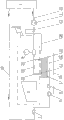
Fig. 1 is an integrally-built systematic schematic diagram of the present invention, Fig. 2 is the systematic schematic diagram (arrow is represented the flow direction of cycle fluid among the figure) of accumulation of heat pattern of the present invention, Fig. 3 is the systematic schematic diagram (arrow is represented the flow direction of cycle fluid among the figure) of normal operation mode of the present invention, and Fig. 4 is the systematic schematic diagram (arrow is represented the flow direction of cycle fluid among the figure) of antifreeze operational mode of the present invention.
The specific embodiment
The specific embodiment one: present embodiment is described in conjunction with Fig. 1-Fig. 4, the heat accumulating type anti-freeze solar heat collector system of present embodiment comprises solar thermal collector 2, first water circulating pump 4, hot user 5, first check-valves 7, the 4th stop valve 13, cycle fluid effuser 20 and cycle fluid inflow pipe 21, hot user's 5 outflow end is communicated with solar thermal collector 2 by cycle fluid effuser 20, first check-valves 7 is installed on the cycle fluid effuser 20, hot user's 5 inflow end is communicated with solar thermal collector 2 by cycle fluid inflow pipe 21, the flow direction that the 4th stop valve 13 and first water circulating pump 4 follow ring working medium is installed on the cycle fluid inflow pipe 21 successively, described anti-freeze solar heat collector system also comprises phase-change material heat-accumulator tank 1, second water circulating pump 6, second check-valves 8, temperature sensor 9, first stop valve 10, second stop valve 11, the 3rd stop valve 12, cycle fluid return duct 22, first communicating pipe 23, second communicating pipe 24, first control line 25 and second control line 26, the flow direction that described first stop valve 10 and temperature sensor 9 follow ring working medium is installed on the cycle fluid inflow pipe 21 successively, and first stop valve 10 and temperature sensor 9 are on the cycle fluid inflow pipe 21 between solar thermal collector 2 and the 4th stop valve 13, one end of described cycle fluid return duct 22 is communicated with cycle fluid inflow pipe 21 between first stop valve 10 and the temperature sensor 9, the other end of cycle fluid return duct 22 is communicated with cycle fluid effuser 20 between first check-valves 7 and the solar thermal collector 2, the flow direction that described second check-valves 8 and second water circulating pump 6 follow ring working medium is installed on the cycle fluid return duct 22 successively, described first communicating pipe 23 and second communicating pipe 24 are set up in parallel the both sides at first stop valve 10, the upper end of first communicating pipe 23 and second communicating pipe 24 all is communicated with cycle fluid inflow pipe 21, the lower end of first communicating pipe 23 is communicated with the entrance point of phase-change material heat-accumulator tank 1, the lower end of second communicating pipe 24 is communicated with the port of export of phase-change material heat-accumulator tank 1, second stop valve 11 was installed on first communicating pipe 23, the 3rd stop valve 12 was installed on second communicating pipe 24, described temperature sensor 9 is connected with second water circulating pump 6 by first control line 25, and temperature sensor 9 is connected with the 4th stop valve 13 by second control line 26.
The specific embodiment two: present embodiment is described in conjunction with Fig. 1-Fig. 4, the anti-freeze solar heat collector system of present embodiment also increases expansion tank 3 and third connecting pipe 27, described expansion tank 3 is communicated with cycle fluid inflow pipe 21 by third connecting pipe 27, and third connecting pipe 27 is on the cycle fluid inflow pipe 21 between temperature sensor 9 and the 4th stop valve 13.So be provided with, play the effect of level pressure supply.Other composition is identical with the specific embodiment one with annexation.
Accumulation of heat pattern of the present invention (referring to Fig. 2): first stop valve 10 is closed, and second stop valve 11, the 3rd stop valve 12, the 4th stop valve 13 are opened; Cycle fluid flows out from hot user 5, after entering solar thermal collector 2 and heating up, enters in the phase-change material heat-accumulator tank 1 the phase-change material accumulation of heat in the phase-change material heat-accumulator tank 1 through second stop valve 11; Cycle fluid resupplies hot user 5 through the 3rd stop valve 12, first water circulating pump 4 afterwards; Expansion tank 3 plays the effect of level pressure supply.The phase-change material accumulation of heat that the accumulation of heat pattern is carried out in phase-change material heat-accumulator tank 1 always finishes.
Normal operation mode of the present invention (referring to Fig. 3): the temperature of the interior cycle fluid of solar energy collector system this moment is higher than its freezing point, because this moment, system need not antifreeze, and accumulation of heat finishes, close second stop valve 11 and the 3rd stop valve 12, open first stop valve 10 and the 4th stop valve 13, cycle fluid flows out from hot user 5, through first check-valves 7, after entering solar thermal collector 2 intensifications, resupply hot user 5 through the 4th stop valve 13, first water circulating pump 4.Described expansion tank 3 plays the effect of level pressure supply.
Antifreeze operational mode of the present invention (referring to Fig. 4): the temperature of the interior cycle fluid of solar energy collector system this moment is lower than its freezing point, because this moment, system needed antifreeze, first stop valve 10 and the 4th stop valve 13 are closed, second stop valve 11 and the 3rd stop valve 12 are opened, indoor section with first water circulating pump 4 close and stop the circulation; Cycle fluid flows out from solar thermal collector 2, through second stop valve 11, enter in the phase-change material heat-accumulator tank 1, cycle fluid is warmed up to more than the freezing point, the 3rd stop valve 12 of flowing through again enters in the cycle fluid return duct 22, turns back in the solar thermal collector 2 through second water circulating pump 6 more again.
Claims (2)
1. heat accumulating type anti-freeze solar heat collector system, it comprises solar thermal collector (2), first water circulating pump (4), hot user (5), first check-valves (7), the 4th stop valve (13), cycle fluid effuser (20) and cycle fluid inflow pipe (21), hot user's (5) outflow end is communicated with solar thermal collector (2) by cycle fluid effuser (20), first check-valves (7) is installed on the cycle fluid effuser (20), hot user's (5) inflow end is communicated with solar thermal collector (2) by cycle fluid inflow pipe (21), the flow direction that the 4th stop valve (13) and first water circulating pump (4) follow ring working medium is installed on the cycle fluid inflow pipe (21) successively, it is characterized in that: described anti-freeze solar heat collector system also comprises phase-change material heat-accumulator tank (1), second water circulating pump (6), second check-valves (8), temperature sensor (9), first stop valve (10), second stop valve (11), the 3rd stop valve (12), cycle fluid return duct (22), first communicating pipe (23), second communicating pipe (24), first control line (25) and second control line (26), the flow direction that described first stop valve (10) and temperature sensor (9) follow ring working medium is installed on the cycle fluid inflow pipe (21) successively, and first stop valve (10) and temperature sensor (9) are positioned on the cycle fluid inflow pipe (21) between solar thermal collector (2) and the 4th stop valve (13), one end of described cycle fluid return duct (22) is communicated with cycle fluid inflow pipe (21) between first stop valve (10) and the temperature sensor (9), the other end of cycle fluid return duct (22) is communicated with cycle fluid effuser (20) between first check-valves (7) and the solar thermal collector (2), the flow direction that described second check-valves (8) and second water circulating pump (6) follow ring working medium is installed on the cycle fluid return duct (22) successively, described first communicating pipe (23) and second communicating pipe (24) are set up in parallel the both sides in first stop valve (10), the upper end of first communicating pipe (23) and second communicating pipe (24) all is communicated with cycle fluid inflow pipe (21), the lower end of first communicating pipe (23) is communicated with the entrance point of phase-change material heat-accumulator tank (1), the lower end of second communicating pipe (24) is communicated with the port of export of phase-change material heat-accumulator tank (1), second stop valve (11) was installed on first communicating pipe (23), the 3rd stop valve (12) was installed on second communicating pipe (24), described temperature sensor (9) is connected with second water circulating pump (6) by first control line (25), and temperature sensor (9) is connected with the 4th stop valve (13) by second control line (26).
2. according to the described heat accumulating type anti-freeze solar heat collector system of claim 1, it is characterized in that: anti-freeze solar heat collector system also comprises expansion tank (3) and third connecting pipe (27), expansion tank (3) is communicated with cycle fluid inflow pipe (21) by third connecting pipe (27), and third connecting pipe (27) is positioned on the cycle fluid inflow pipe (21) between temperature sensor (9) and the 4th stop valve (13).
Priority Applications (1)
| Application Number | Priority Date | Filing Date | Title |
|---|---|---|---|
| CN2010101527517A CN101825350B (en) | 2010-04-22 | 2010-04-22 | Heat accumulating type anti-freeze solar heat collector system |
Applications Claiming Priority (1)
| Application Number | Priority Date | Filing Date | Title |
|---|---|---|---|
| CN2010101527517A CN101825350B (en) | 2010-04-22 | 2010-04-22 | Heat accumulating type anti-freeze solar heat collector system |
Publications (2)
| Publication Number | Publication Date |
|---|---|
| CN101825350A CN101825350A (en) | 2010-09-08 |
| CN101825350B true CN101825350B (en) | 2011-07-20 |
Family
ID=42689414
Family Applications (1)
| Application Number | Title | Priority Date | Filing Date |
|---|---|---|---|
| CN2010101527517A Expired - Fee Related CN101825350B (en) | 2010-04-22 | 2010-04-22 | Heat accumulating type anti-freeze solar heat collector system |
Country Status (1)
| Country | Link |
|---|---|
| CN (1) | CN101825350B (en) |
Families Citing this family (3)
| Publication number | Priority date | Publication date | Assignee | Title |
|---|---|---|---|---|
| CN103940125B (en) * | 2014-04-10 | 2016-03-23 | 哈尔滨工业大学 | The control method of intelligent circulation antifreezing solar energy control system and this system |
| CN104110899A (en) * | 2014-08-01 | 2014-10-22 | 金赛博阳(北京)科技有限公司 | Solar light and heat convertor |
| CN110986382A (en) * | 2019-12-27 | 2020-04-10 | 长春工程学院 | Distributed solar heat pipe heat collection and storage self-circulation heating system and heating method |
Citations (4)
| Publication number | Priority date | Publication date | Assignee | Title |
|---|---|---|---|---|
| CN1912477A (en) * | 2006-07-19 | 2007-02-14 | 北京工业大学 | Full heat recovery fresh air energy-saving system of using solar phase transformation thermal storage |
| CN101033900A (en) * | 2007-04-18 | 2007-09-12 | 哈尔滨工业大学 | Three casing pipes energy accumulating solar and air resource heat pump integrated system |
| CN101059280A (en) * | 2006-04-18 | 2007-10-24 | 同济大学 | Solar energy-storage hot water heat-supply system |
| CN101424470A (en) * | 2008-10-27 | 2009-05-06 | 湘潭市宇恒电器科技有限公司 | Wind-cooling heat pump defrosting, compensating and energy-saving equipment by utilizing solar |
Family Cites Families (2)
| Publication number | Priority date | Publication date | Assignee | Title |
|---|---|---|---|---|
| JPH11148728A (en) * | 1997-11-18 | 1999-06-02 | Toyota Motor Corp | Solar heat hot-water supplier and operating method thereof |
| JP4036864B2 (en) * | 2004-12-27 | 2008-01-23 | 三洋電機株式会社 | Solar power system |
-
2010
- 2010-04-22 CN CN2010101527517A patent/CN101825350B/en not_active Expired - Fee Related
Patent Citations (4)
| Publication number | Priority date | Publication date | Assignee | Title |
|---|---|---|---|---|
| CN101059280A (en) * | 2006-04-18 | 2007-10-24 | 同济大学 | Solar energy-storage hot water heat-supply system |
| CN1912477A (en) * | 2006-07-19 | 2007-02-14 | 北京工业大学 | Full heat recovery fresh air energy-saving system of using solar phase transformation thermal storage |
| CN101033900A (en) * | 2007-04-18 | 2007-09-12 | 哈尔滨工业大学 | Three casing pipes energy accumulating solar and air resource heat pump integrated system |
| CN101424470A (en) * | 2008-10-27 | 2009-05-06 | 湘潭市宇恒电器科技有限公司 | Wind-cooling heat pump defrosting, compensating and energy-saving equipment by utilizing solar |
Non-Patent Citations (4)
| Title |
|---|
| JP特开2006-183933A 2006.07.13 |
| JP特开平11-148728A 1999.06.02 |
| 姜益强等.太阳能季节性相变蓄热热泵系统在哈尔滨应用的模拟研究.《暖通空调》.2007,第37卷(第3期),第15-20页. * |
| 韩志涛等.空气源热泵蓄能热气除霜新系统与实验研究.《哈尔滨工业大学学报》.2007,第39卷(第6期),第901-903页. * |
Also Published As
| Publication number | Publication date |
|---|---|
| CN101825350A (en) | 2010-09-08 |
Similar Documents
| Publication | Publication Date | Title |
|---|---|---|
| CN102589070B (en) | A kind of solar air source heat pumps hot water air-conditioning system | |
| CN206398895U (en) | The composite heating air-conditioning system of air source heat pump and water source heat pump combining | |
| CN101825350B (en) | Heat accumulating type anti-freeze solar heat collector system | |
| CN101718477A (en) | Solar thermal collector freezing prevention system | |
| CN202692493U (en) | Highly-integrated non-pressure operation confined water tank | |
| CN204535084U (en) | Low-temperature heat pump water heater | |
| CN213811154U (en) | Frost protection system for water medium air heater | |
| CN101818941B (en) | Air heated anti-freezing solar energy collector system | |
| CN202442525U (en) | Novel replacement heat exchange solar water heater | |
| CN105222342A (en) | Enhanced heat exchange formula heat pump | |
| CN2750244Y (en) | Solar energy heat pump water heater | |
| CN108204625A (en) | Solar-energy air-energy geothermal heat pipeline evacuation and anti-freezing system | |
| CN201014799Y (en) | Secondary circulation solar water heater | |
| CN202757313U (en) | Solar energy water heater anti-freezing tube device | |
| CN202339017U (en) | Low-pressure closed solar water heating system of flat plate collector | |
| CN104676860A (en) | Expansion tank design | |
| CN203785296U (en) | System for preventing flat plate type solar heat collector from frost cracking | |
| CN108561939B (en) | Waste heat utilization device based on phase change heat exchange technology | |
| CN201184701Y (en) | Double-pump workstation for solar heating system | |
| CN202204205U (en) | Single-pipe natural emptying solar water heater | |
| CN219414954U (en) | Bypass device for preventing middle deep central tube from deforming | |
| CN201497224U (en) | Special direct-acting electromagnetic valve for energy-saving anti-freezing solar water heater pipeline | |
| CN202153022U (en) | Radiator water heater | |
| CN203116331U (en) | Solar energy thermal-collecting engineering protecting device | |
| CN205505492U (en) | Grouping ground source heat pump system with journey setting |
Legal Events
| Date | Code | Title | Description |
|---|---|---|---|
| C06 | Publication | ||
| PB01 | Publication | ||
| C10 | Entry into substantive examination | ||
| SE01 | Entry into force of request for substantive examination | ||
| C14 | Grant of patent or utility model | ||
| GR01 | Patent grant | ||
| C17 | Cessation of patent right | ||
| CF01 | Termination of patent right due to non-payment of annual fee |
Granted publication date: 20110720 Termination date: 20130422 |