Reversing control valve, reverse dosing filling machine and packaging process thereof
Technical field
The present invention relates to the liquid filling device art, refer in particular to a kind of reversing control valve, reverse dosing filling machine and packaging process thereof.
Background technology
Bottle placer is a kind of for air containing fluid, air containing fluid, the various filling materials of body of paste are not filled into the mechanical equipment of various packing containers such as bottle, jar, box, bucket or bag, adopt the mechanization can not only can raise labour productivity, reduce product losses, guarantee packaging quality, and can reduce production environment and the mutual pollution of being adorned material.Therefore, present bottle placer has been widely used in the automated job can production of medicine, daily use chemicals, food and special industry factory.Divide by the can principle, bottle placer includes vacuum filling machine, atmospherical pressure filling machine, counter pressure filling machine, low vacuum filling machine or pressurization bottle placer etc.
Yet, though above-mentioned existing bottle placer can be realized the basic function of its can operation, but when using, reality finds still to have many deficiencies on himself structure and the in-use performance, fail to reach result of use and the task performance of the best.Its weak point especially is embodied in: in pouring process, exhaust during can and the control liquid level after the can are two different actions, corresponding these two different action orthodox methods are to use two different devices to realize, and for the control liquid level after the can, general easy device is difficult to accomplish fast and actv. is accurately controlled, must use comparatively complicated induction installations such as electronics package if need accomplish the accurate control of liquid level, thereby improved productive costs, do not utilized to save production cost and enhance productivity.
Summary of the invention
Main purpose of the present invention provides a kind of reversing control valve, reverse dosing filling machine and packaging process thereof, and it is the function that vacuumizes the control liquid level in the time of can realizing can by utilizing a reversing control valve to switch air flow line after exhaust and the can.
Another object of the present invention provides a kind of reversing control valve, reverse dosing filling machine and packaging process thereof, and it has more accurate reliable and quick can quantitation capabilities.
For achieving the above object, the present invention adopts following technical scheme:
A kind of reverse dosing filling machine, include support and the liquid feed device that is arranged on the support, be disposed with cover bottle and bottle jacking system in the liquid feed device below, further include reversing control valve, vacuumize the control liquid level after exhaust and the can when reversing control valve is used for can, include
One valve body has a cavity in this valve body, valve body is provided with admission port, exhausr port and the bleeding point that is communicated with cavity; This admission port is connected with a tracheae that can stretch into bottle inside; This exhausr port is communicated with the back pressure district of liquid feed device or directly is communicated with ambient atmosphere, the exhaust when being used for can; This bleeding point connects vacuum-pumping pipeline, is used for vacuumizing the control liquid level after the can;
Two spools, this two spool is arranged in the aforementioned cavity, is respectively applied to shutoff exhausr port and bleeding point;
One spool control setup, open or shutoff exhausr port and bleeding point by correspondence for control two spools move for this spool control setup, and this spool control setup includes tabular body, actuating device and elasticity reset device; This tabular body is positioned at the same side of two spools, is provided with a high position and low level in a side of tabular body; This actuating device is two cams, this two cam is installed on the support, two cams and tabular body are inconsistent and lay respectively at the above and below of tabular body, moved by this driving device controls tabular body, make an end of two spools alternately impel corresponding spool to a side shifting with the high-order inconsistent of tabular body with moving up and down of tabular body; This elasticity reset device acts on the other end of two spools and impels two spools to the reverse reset movement of opposite side;
When opening exhausr port by spool control setup control spool shutoff bleeding point, exhausr port is communicated with admission port, is used for the exhaust of pouring process;
During the shutoff exhausr port, bleeding point is communicated with admission port, vacuumizes the control liquid level after finishing for can when opening bleeding point by spool control setup control spool.
As a kind of preferred version, described elasticity reset device is a pressure spring, and an end of this pressure spring pushes on the end face of spool, and the other end of pressure spring then pushes on the valve interior wall face.
As a kind of preferred version, described liquid feed device includes fluid reservoir and filling control valve, is provided with discharging opening in the fluid reservoir, and the filling control valve is used for opening and cutting out of control discharging opening; This filling control valve includes movable valve, fixedly cock body and pressure spring; Be provided with the cavity that is communicated with fluid reservoir inside in this movable valve, movable valve is provided with the can outlet that is communicated with this cavity simultaneously; Should be fixedly cock body be installed in the cavity, movable valve relative fixed cock body moves and opens or close can and export; One end of this pressure spring pushes on fluid reservoir, and the other end of pressure spring pushes on movable valve, and pressure spring is used for movable valve is automatically reset.
As a kind of preferred version, described bottle jacking system includes cylinder, piston rod and bottle carriage, by this air cylinder driven bottle carriage along piston rod up and down straight line move.
A kind of reversing control valve, include a valve body, has a cavity in this valve body, be provided with entrance and at least two outlets that are communicated with cavity in valve body, be provided with the spool that can be used for this outlet of shutoff corresponding to each outlet, further comprise a spool control setup, open or each outlet of shutoff by correspondence for the control spool moves for this spool control setup, and this spool control setup includes tabular body, actuating device and elasticity reset device; This tabular body is positioned at the same side of two spools, is provided with a high position and low level in a side of tabular body; This actuating device is two cams, two cams and tabular body are inconsistent and lay respectively at the above and below of tabular body, moved by this driving device controls tabular body, make an end of two spools alternately impel corresponding spool to a side shifting with the high-order inconsistent of tabular body with moving up and down of tabular body; This elasticity reset device acts on the other end of two spools and impels two spools to the reverse reset movement of opposite side.
As a kind of preferred version, described spool control setup includes tabular body, actuating device and elasticity reset device; This tabular body is positioned at a side of spool, is provided with a high position and low level in a side of tabular body, is moved by this driving device controls tabular body, makes the high-order inconsistent spool that impels of an end of spool and tabular body to a side shifting with the movement of tabular body; This elasticity reset device acts on the other end of spool and impels spool to the reverse reset movement of opposite side.
As a kind of preferred version, described elasticity reset device is a pressure spring, and an end of this pressure spring pushes on the end face of spool, and the other end then pushes on the internal face of valve body.
A kind of packaging process, it is by the filling control valve of opening liquid feed device bottle to be carried out can, utilize a reversing control valve to carry out exhaust and control liquid level in the pouring process, this reversing control valve includes a valve body, has a cavity in this valve body, be provided with entrance and at least two outlets that are communicated with cavity in valve body, be provided with the spool that can be used for this outlet of shutoff corresponding to each outlet, further comprise a spool control setup, open or each outlet of shutoff by correspondence for the control spool moves for this spool control setup, and this spool control setup includes tabular body, actuating device and elasticity reset device; This tabular body is positioned at the same side of two spools, is provided with a high position and low level in a side of tabular body; This actuating device is two cams, two cams and tabular body are inconsistent and lay respectively at the above and below of tabular body, moved by this driving device controls tabular body, make an end of two spools alternately impel corresponding spool to a side shifting with the high-order inconsistent of tabular body with moving up and down of tabular body; This elasticity reset device acts on the other end of two spools and impels two spools to the reverse reset movement of opposite side; Wherein, during can, utilize reversing control valve to switch air flow line, make bottle carry out exhaust by the back pressure district of tracheae and liquid feed device or extraneous the connection; When can puts in place, close the filling control valve and stop can, utilize reversing control valve to switch air flow line simultaneously, bottle is connected by tracheae and vacuum-pumping pipeline bleeds, and take the material that covered the tracheae lower end away, make material remain on height near the tracheae lower surface, realize the accurate control of liquid level.
The present invention compared with prior art has tangible advantage and beneficial effect, particularly, and as shown from the above technical solution:
One, by utilizing a reversing control valve to carry out the switching controls of air-flow, and vacuumize the control liquid level after the exhaust can realize can time the and the can, this two action can be switched mutually, and is simple in structure, easy and simple to handle, is conducive to save production cost.
Two, vacuumize and rapidly the material that covered tracheae to be taken away by utilization, make material remain on height near the tracheae lower end, and can more accurately control the can amount, improve can liquid level control accuracy, be conducive to guarantee the reliability of can.
Three, the present invention's commutation dosing filling machine also has the advantage that makes things convenient for fluid reservoir and filling control valve to clean.Be widely used in the auto-filling of various can media such as fruit juice, tea beverage, liquid milk, vegetable juice, sports drink, mineral water, mineral water, carbonated beverage or beer, and the can operation of various PET bottle or glass bottle.
For more clearly setting forth architectural feature of the present invention and effect, the present invention is described in detail below in conjunction with accompanying drawing and specific embodiment:
Description of drawings
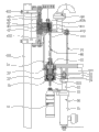
Fig. 1 is the integral structure diagram of the present invention's embodiment, and bottle is in lowering position among the figure;
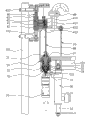
Fig. 2 is another mode of operation diagram of Fig. 1, and bottle rises to the preparation filling position among the figure;
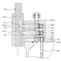
Fig. 3 is the main body structure for amplifying diagram of reversing control valve among the present invention's the embodiment;
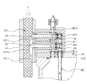
Fig. 4 is another mode of operation diagram of Fig. 3;
Fig. 5 is the mode of operation diagram again of Fig. 3.
The accompanying drawing identifier declaration:
10, fluid reservoir 11, discharging opening
20, filling control valve 21, upper valve body
22, valve body 221, can outlet down
23, pressure spring 24, fixing cock body
25, cavity 30, bottle jacking system
31, cylinder 32, piston rod
33, bottle carriage 40, reversing control valve
41, valve body 411, cavity
412, admission port 413, exhausr port
414, bleeding point 42, spool
43, spool control setup 431, tabular body
4311, a high position 4312, low level
432, cam 433, pressure spring
44, seal ring 50, bottle
60, total blow off valve 70, cover bottle
80, tracheae 101, support
The specific embodiment:
Please refer to Fig. 1 to shown in Figure 5, the concrete structure that it has demonstrated the present invention's preferred embodiment comprises fluid reservoir 10, filling control valve 20, bottle jacking system 30, reversing control valve 40.
Wherein, this fluid reservoir 10 is installed on the support 101, and fluid reservoir 10 is used for storing the materials such as various water, fruit juice, beverage or cola that need be filled in the bottle 50 as a kind of component part of liquid feed device.Be provided with a discharging opening 11 in the lower end of this fluid reservoir 10, further be provided with total blow off valve 60 in the top of fluid reservoir 10, this total blow off valve 60 is communicated with fluid reservoir 10 inside, the total exhaust when being used for can.
This filling control valve 20 is installed on discharging opening 11 belows of aforementioned fluid reservoir 10, is used for opening and closing of control discharging opening 11.This filling control valve 20 includes upper valve body 21, down valve body 22, pressure spring 23 and fixing cock body 24.This upper valve body 21 is installed on the fluid reservoir 10, and following valve body 22 is movable valve body, and this upper valve body 21 and 22 butt joints of following valve body surround and form a cavity 25, and this cavity 25 is communicated with fluid reservoir 10.Be provided with the can outlet 221 that is communicated with cavity 25 on this time valve body 22 simultaneously.One end of this pressure spring 23 pushes on upper valve body 21, and the other end of pressure spring 23 pushes on following valve body 22.This time valve body 22 can move relative to upper valve body 21, and can be resetted by pressure spring 23.Fixedly cock body 24 is installed in the cavity 25, is used for shutoff can outlet 221.When the bottleneck with bottle 50 will descend valve body 22 jack-up, can outlet 221 is opened, material in the fluid reservoir 10 flows in the bottle 50 by can outlet 221, when bottle 50 during away from following valve body 22, by pressure spring 23 valve body 22 is resetted, fixedly cock body 24 blocks can outlet 221 and stops can.In addition, be installed with a cover bottle 70 in the below of the can outlet 221 of valve body 22 down, this cover bottle 70 forms sealing with the bottleneck outer rim of bottle 50, and then realizes the sealing can, to guarantee the can quality.
This bottle jacking system 30 is arranged at the below of fluid reservoir 10, be used for realizing the lifting of bottle 50, the operating altitude of control bottle 50 and approach backs down that filling control valve 20 carries out the can of material or stop can away from filling control valve 20, also is used for changing automatically bottle 50 simultaneously to realize the effect of rapid batch can.Bottle jacking system 30 includes cylinder 31, piston rod 32 and bottle carriage 33, by this cylinder 31 drive bottle carriages 33 along piston rod about in the of 32 straight line move, utilize the lifting that slides up and down to drive bottle 50 of this bottle carriage 32.
This reversing control valve 40 includes a valve body 41, two spools 42 and a spool control setup 43.
Wherein, this valve body 41 is installed in the top of aforementioned fluid reservoir 10, has a cavity 411 in the valve body 41, simultaneously, is provided with admission port 412, exhausr port 413 and the bleeding point 414 that is communicated with cavity 411 in valve body 41.This admission port 412 is connected with a tracheae 80 that can stretch into bottle 50 inside, and the tracheae 80 in the present embodiment passes aforementioned fixedly cock body 24 and extends to bottle 50 inside, not to be limited.This exhausr port 413 is communicated with the inside of aforementioned fluid reservoir 10, the exhaust when being used for can.This bleeding point 414 is communicated with vacuum-pumping pipeline, is used for vacuumizing the liquid level of controlling in the bottle 50 after the can.
This two spool 42 is arranged side by side in aforementioned cavity 411, and wherein, the spool 42 that is positioned at upside is used for shutoff bleeding point 414, and the spool 422 that is positioned at downside is used for shutoff exhausr port 413.Simultaneously, can form the better seal performance for making two spools 42 and bleeding point 414 or exhausr port 413, be provided with seal ring 44 in spool 42.
Open or shutoff exhausr port 413 and bleeding point 414 by correspondence for control two spools 42 move for this spool control setup 43, and the spool control setup 43 in the present embodiment includes a tabular body 431, two cams 432 and two pressure springs 433, but is not limited to this.Wherein, this tabular body 431 is positioned at the left side of spool 42, is provided with high-order 4311 and low level 4312 in the right flank of tabular body 431.This two cam 432 is used for driving tabular body 431 and moves, and two cams 432 are to be installed on the support 101, and two cams 432 contact the above and below that lays respectively at tabular body 431 with tabular body 431.Control tabular body 431 moves up and down perpendicular to the moving direction of spool 42 by these two cams, 432 drivings, make the left side of spool 42 and a high position 4311 inconsistent spools 42 that impel of tabular body 431 move to the right with moving up and down of tabular body 431, spool 42 movement to the right can be realized opening of exhausr port 413 or bleeding point 414.One end of this pressure spring 433 pushes on the right side of spool 42, the other end of pressure spring 433 then pushes on the internal face of aforementioned valve body 41, and pressure spring 433 is used for impelling the reverse to the left reset movement of spool 42 and shutoff exhausr port 413 or bleeding point 414.
As Fig. 3, the spool 42 of downside is in high-order 4311 the time when making the spool 42 of upside be in low level 4312 by this spool control setup 43 control tabular bodys 431, exhausr port 413 is opened, and bleeding point 414 is by shutoff, exhausr port 413 is communicated with admission port 412, be used for the exhaust of pouring process, utilize the deadweight of material to be filled into bottle 50 inside.
As Fig. 4, when making two spools 42 be in low level 4312 simultaneously by these spool control setup 43 control tabular bodys 431 be, exhausr port 413 and bleeding point 414 are simultaneously by shutoff, and can can't be carried out exhaust, and can stops.
As Fig. 5, when the spool 42 of downside is in low level 4312 when making the spool 42 of upside be in a high position 4311 by these spool control setup 43 control tabular bodys 431, exhausr port 413 is by shutoff, and bleeding point 414 is opened, bleeding point 414 is communicated with admission port 412, vacuumizing after finishing for can, and utilization vacuumizes the material of taking tracheae 80 lower ends away, make material remain on height near tracheae 80 lower surfaces, realize the accurate control of liquid level.
During use, the switching that vacuumizes two actions of control liquid level after exhaust when the pouring process of present embodiment utilizes reversing control valve 40 to realize can and the can, concrete working process and principle are as follows: before the beginning can, at first need pour into the material of q.s in fluid reservoir 10, at this moment, as shown in Figure 1, the fixedly cock body 24 of this filling control valve 20 blocks in the can outlet 221, close can outlet 221, do not have material to flow out.
During the beginning can, as shown in Figure 2, at first, utilize reversing control valve 40 to switch the direction of air-flow, the method of switching is: by spool control setup 43 control spools 42, tabular body 431 is moved up, as Fig. 3, when tabular body 431 is moved upwards up to end position, the spool 42 of this upside is in low level 4312 and blocks bleeding point 414, the spool 42 of this downside then is in a high position 4311 and opens exhausr port 413, and at this moment, exhausr port 413 is communicated with admission port 412.Then, use bottle jacking system 30 to hold up bottle 50, the bottleneck of bottle 50 peaks at the below of cover bottle 70 and forms sealing with the external world, and tracheae 80 stretches into bottle 50 inside.Continue to apply dynamics and will descend valve body 22 jack-up, can outlet 221 is opened thus, material utilization deadweight flow in bottle 50 inside, and the air in the bottle 50 is then by tracheae 80 successively flow through reversing control valve 40 and fluid reservoir 10 inside, and finally discharges by total blow off valve 60.In addition, this kind exhaust condition of reversing control valve 40 can be applied to clean liquid storage cylinder 10, only needs to inject water or other cleaning liquids toward liquid storage cylinder 10, namely carries out self-loopa and cleans.
When the liquid level of the material in the bottle 50 was increased to the lower nozzle that touches tracheae 80, tracheae 80 lower ends were sealed by liquid, because the gas in the bottle 50 can't be discharged by tracheae 80 again, can is stopped.Then, control bottle jacking system 30 descends, bottle 50 is away from following valve body 22, by pressure spring 23 valve body 22 is resetted, fixedly cock body 24 blocks can outlet 221 and closes the filling control valve, bottle continues to descend then, about 1 to 2mm the time apart from the sealing surface of cover bottle 70 until bottleneck, switch air flow line, the method of switching is by spool control setup 43 control spools 42 equally, tabular body 431 moves down, as Fig. 4, make two spools 42 all be in low level 4312, exhausr port 413 and bleeding point 414 are simultaneously by shutoff, continuing that then reversing control valve 40 is switched to the third state enters and vacuumizes the control liquid level, method is by spool control setup 43 control spools 42 equally, as Fig. 5, make the spool 42 of upside be in a high position 4311 and open bleeding point 414, the spool 42 of this downside then is in low level 4312 and blocks exhausr port 413, at this moment, bleeding point 414 is communicated with admission port 412, because bleeding point 414 links to each other with vacuum-pumping pipeline simultaneously, has namely entered in the state of vacuumizing, the material that covered tracheae 80 lower ends is namely taken away, this step can make material remain on height near tracheae 80 lower surfaces, realizes the accurate control of liquid level.In addition, this kind state of reversing control valve 40 can be applicable to clean in the filling control valve 20, and cleaning liquid enters filling control valve 20 by liquid storage cylinder 10 and flow in the bottle 50, the dirt that cleans is discharged by vacuum-pumping pipeline through tracheae 80 to get final product again.
At last, the liquid level in the bottle 50 is stablized, and bottle 50 continues to break away from tracheae 80 fully away from filling control valve 20 to bottleneck, by defeated bottle star-wheel the bottle 50 of can good beverage is delivered to other places again.
Switching according to need can circulate between above three kinds of states of reversing control valve 40.
In sum, design focal point of the present invention is, main system utilizes a reversing control valve to carry out the switching of air flow line, vacuumize the control liquid level after exhaust when utilizing this device just can be realized and the can, this two action can be switched mutually, simple in structure, easy and simple to handle, be conducive to save production cost.Secondly, vacuumize and rapidly the material that covered tracheae to be taken away by utilization, make material remain on height near the tracheae lower end, and can more accurately control the can amount, improve the filling control precision, be conducive to guarantee the reliability of can.In addition, the present invention's commutation dosing filling machine also has the advantage that makes things convenient for fluid reservoir and filling control valve to clean.Be widely used in the auto-filling of various can media such as fruit juice, tea beverage, liquid milk, vegetable juice, sports drink, mineral water, mineral water, carbonated beverage or beer, and the can operation of various PET bottle or glass bottle.
The above, it only is preferred embodiment of the present invention, be not that technical scope of the present invention is imposed any restrictions, so every foundation technical spirit of the present invention all still belongs in the scope of technical solution of the present invention any trickle modification, equivalent variations and modification that above embodiment does.