CN101795343A - Image processing apparatus and image processing method - Google Patents
Image processing apparatus and image processing method Download PDFInfo
- Publication number
- CN101795343A CN101795343A CN201010106699A CN201010106699A CN101795343A CN 101795343 A CN101795343 A CN 101795343A CN 201010106699 A CN201010106699 A CN 201010106699A CN 201010106699 A CN201010106699 A CN 201010106699A CN 101795343 A CN101795343 A CN 101795343A
- Authority
- CN
- China
- Prior art keywords
- point
- unit
- image processing
- image
- appended drawings
- Prior art date
- Legal status (The legal status is an assumption and is not a legal conclusion. Google has not performed a legal analysis and makes no representation as to the accuracy of the status listed.)
- Pending
Links
Images


Classifications
-
- H—ELECTRICITY
- H04—ELECTRIC COMMUNICATION TECHNIQUE
- H04N—PICTORIAL COMMUNICATION, e.g. TELEVISION
- H04N1/00—Scanning, transmission or reproduction of documents or the like, e.g. facsimile transmission; Details thereof
- H04N1/00838—Preventing unauthorised reproduction
- H04N1/0084—Determining the necessity for prevention
- H04N1/00843—Determining the necessity for prevention based on recognising a copy prohibited original, e.g. a banknote
- H04N1/00846—Determining the necessity for prevention based on recognising a copy prohibited original, e.g. a banknote based on detection of a dedicated indication, e.g. marks or the like
-
- H—ELECTRICITY
- H04—ELECTRIC COMMUNICATION TECHNIQUE
- H04N—PICTORIAL COMMUNICATION, e.g. TELEVISION
- H04N1/00—Scanning, transmission or reproduction of documents or the like, e.g. facsimile transmission; Details thereof
- H04N1/00838—Preventing unauthorised reproduction
- H04N1/00856—Preventive measures
- H04N1/00864—Modifying the reproduction, e.g. outputting a modified copy of a scanned original
- H04N1/00867—Modifying the reproduction, e.g. outputting a modified copy of a scanned original with additional data, e.g. by adding a warning message
- H04N1/0087—Modifying the reproduction, e.g. outputting a modified copy of a scanned original with additional data, e.g. by adding a warning message with hidden additional data, e.g. data invisible to the human eye
-
- H—ELECTRICITY
- H04—ELECTRIC COMMUNICATION TECHNIQUE
- H04N—PICTORIAL COMMUNICATION, e.g. TELEVISION
- H04N1/00—Scanning, transmission or reproduction of documents or the like, e.g. facsimile transmission; Details thereof
- H04N1/00838—Preventing unauthorised reproduction
- H04N1/00883—Auto-copy-preventive originals, i.e. originals that are designed not to allow faithful reproduction
-
- H—ELECTRICITY
- H04—ELECTRIC COMMUNICATION TECHNIQUE
- H04N—PICTORIAL COMMUNICATION, e.g. TELEVISION
- H04N2201/00—Indexing scheme relating to scanning, transmission or reproduction of documents or the like, and to details thereof
- H04N2201/0077—Types of the still picture apparatus
- H04N2201/0094—Multifunctional device, i.e. a device capable of all of reading, reproducing, copying, facsimile transception, file transception
Abstract
The present invention relates to a kind of image processing apparatus and image processing method.When dwindle simply by the sampling of pixel comprise represent by the set of point, during such as the image of the pattern of copy-forgery-inhibited pattern and two-dimension code, point is by close arrangement, makes that downscaled images is whole to show black, and its content indigestion that becomes.Image processing apparatus comprises: dwindle the unit, it is configured to downscaled images; And delete cells, it is configured to delete described appended drawings picture, being comprised at described image under the situation of the appended drawings picture with the information that is hidden in wherein when dwindling the unit and dwindling described image by described.
Description
Technical field
The present invention relates to image processing apparatus, the image processing method of the pattern image of a kind of processing such as copy-forgery-inhibited pattern (copy-forgery-inhibitedpattern) and two-dimension code, the program of carrying out this image processing method and print media.
Background technology
Traditionally, knownly a kind ofly when printing document,, copy-forgery-inhibited pattern image (part (sub-image) that disappears when using photocopier to duplicate and the image of the pattern of part (background) formation of reproduction when duplicating) prints the technology of document (for example referring to TOHKEMY 2004-223854 communique) by being appended to the original document image in order to prevent to duplicate without approval.In addition, knownly a kind of additional information is converted to one dimension sign indicating number (for example bar code) and two-dimension code (for example QR sign indicating number and low visual bar code) and appends to the technology (for example TOHKEMY 2002-305646 communique and TOHKEMY 2008-271110 communique) that the original document image is printed the N dimension yard after the conversion by the dimension of the N after will change sign indicating number.
Aforesaid copy-forgery-inhibited pattern image and N dimension sign indicating number are the images of being represented by the set of point (in this manual, copy-forgery-inhibited pattern image and N dimension sign indicating number being referred to as the appended drawings picture).Therefore, dwindle if added the image of appended drawings picture, then residual many points on the image that dwindles are perhaps put and are emphasized, and grasp sometimes and discern the original document image become the difficulty.
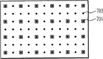
For example, when the pixel by image that as shown in Figure 6 property dot cycle ground is arranged is sampled (sparse (thinning)), when dwindling this image simply, the residual degree of point during according to sampling phase place and marked change.The difference of the phase place of Fig. 7 A when Fig. 7 D shows the picture that dwindles of expression how according to sampling and different figure.In Fig. 7 A, to sampling with the corresponding pixel of the dash area in sampled targets zone 702.In this case, the pixel 701 of the point on the formation original image does not have residual, and therefore, shown in Fig. 7 B, on downscaled images, the pattern of point all disappears.In contrast, in Fig. 7 C, to sampling with the corresponding pixel of the dash area in sampled targets zone 704.In this case, the pixel 703 that forms the point on the original image is residual with high probability, and therefore, shown in Fig. 7 D, on its downscaled images, the pattern of point occurs with high density.
By this way, when by pixel is sampled, and when dwindling the image that comprises the pattern of being represented by the set of point (for example copy-forgery-inhibited pattern and two-dimension code) simply, these points are closely arranged, make downscaled images show black on the whole.Therefore, its content elusive problem that becomes appears.
Summary of the invention
In order to address the above problem, the present invention includes following structure.
Image processing apparatus of the present invention comprises: dwindle the unit, it is configured to downscaled images; And delete cells, it is configured to delete described appended drawings picture, being comprised at described image under the situation of appended drawings picture when dwindling the unit and dwindling described image by described, and described appended drawings looks like to have the information that is hidden in wherein.
Even when the image of the appended drawings picture that comprises pattern (for example copy-forgery-inhibited pattern and the two-dimension code) formation of being represented by the set of point dwindles, also can on downscaled images, stably guarantee the visuality of original original copy.
By following description to exemplary embodiment (with reference to accompanying drawing), it is clear that further feature of the present invention will become.
Description of drawings
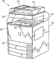
Fig. 1 is the figure that illustrates according to the example of the outward appearance of digital multi ancillary equipment of the present invention;
Fig. 2 is the block diagram that illustrates according to the example of the structure of the control unit of digital multi ancillary equipment of the present invention;
Fig. 3 is the figure that conceptually represents block (tile) data;
Fig. 4 is the in-built block diagram that the scanner graphics processing unit is shown;
Fig. 5 is the in-built block diagram that the printer image processing unit is shown;
Fig. 6 illustrates the periodically figure of the example of layout points;
Fig. 7 A is that the picture that dwindles the how difference of the phase place when point is sampled and the figure of a different example are shown to Fig. 7 D;
Fig. 8 is the figure that the situation that use is printed the situation of the reporting printing (report print) with downscaled images and used conventional art to print the reporting printing with downscaled images according to the digital multi ancillary equipment of present embodiment is compared;
Fig. 9 is the partial enlarged drawing that has added the original image of low visual bar code;
Figure 10 is the figure that the example of the arrangement pattern of hanging down the point in the visual bar code is shown;
Figure 11 is the block diagram that the parts of information analysis unit are shown;
Figure 12 is the figure of the detection method of the point in the explanation point detecting unit;
Figure 13 is the chart that the principle of the point that can not constitute low visual bar code is removed in explanation;
Figure 14 is the flow chart from the series of processing steps that scans type-script that illustrates according to the digital multi ancillary equipment of first embodiment;
Figure 15 A is the figure that the principle of sparse processing visually is described to Figure 15 D;
Figure 16 is the example of having added the image of copy-forgery-inhibited pattern;
Figure 17 is the example of the layout of the point in the copy-forgery-inhibited pattern;
Figure 18 is the flow chart from the series of processing steps that scans type-script that illustrates according to the digital multi ancillary equipment of second embodiment; And
Figure 19 A is the figure of principle of the analyzing and processing of explanation copy-forgery-inhibited pattern to Figure 19 C.
Embodiment
Hereinafter, embodiments of the present invention will be described by referring to the drawings.
[first embodiment]
Fig. 1 is the figure that illustrates according to the outward appearance of the digital multi ancillary equipment 001 of present embodiment.
Fig. 2 is the block diagram of structure that the control unit 100 of digital multi ancillary equipment 001 is shown.
150 pairs of scanner graphics processing units are proofreaied and correct, are handled and edit from the view data that scanner unit 200 receives via scanner interface 113.To be described in the details of the processing of carrying out in the scanner graphics processing unit 150 after a while.
160 pairs of view data that send from decompression unit 114 of printer image processing unit are carried out various image processing.View data after the image processing is outputed to printer unit 300 via printer interface 115.To be described in the details of the processing of carrying out in the printer image processing unit 160 after a while.
The 120 pairs of view data of image conversion unit are carried out intended conversion and are handled, and image conversion unit 120 is made of to 130 as follows each unit 121.
121 pairs of view data that are received in wherein of decompression unit decompress.122 pairs of view data that are received in wherein of compression unit are compressed.123 pairs of view data that are received in wherein of rotary unit are rotated.Unit for scaling 124 is carried out conversion of resolution to the view data of its reception and is handled (for example 600dpi being converted to 200dpi).Color space converting unit 125 conversions are received in the color space of view data wherein.In color space converting unit 125, also carry out brightness concentration conversion process (RGB is to CMY) and output color correction process (CMY is to CMYK).The view data that the many-valued converting unit 126 of two-value will be received in two gray scales (gradation) wherein is converted to the view data of 256 gray scales.In contrast, many-valued two-value converting unit 127 view data that will be received in 256 gray scales wherein by technology such as error diffusion processing is converted to the view data of two gray scales.Synthesis unit 128 synthesizes or distributes two view data that are received in wherein, generates a view data.When synthesizing two view data, the mean value of the brightness value that the pixel that application will be synthesized has is set to the method for synthetic brightness value, or the method for the brightness value of the pixel after the brightness value of pixel brighter on the brightness degree is set to synthesize.In addition, can also use the method for the pixel after darker pixel is set to synthesize.In addition, can use by the pixel that will synthesize is carried out or (OR) computing, with (AND) computing, XOR (EXCLUSIVE-OR) computing etc., determine the method for the brightness value after synthetic.These synthetic methods all are known methods.In addition, for distribution,, come a plurality of view data that synthesis unit 128 receives are distributed, to generate a view data by being included in the method in the control program that is stored in advance among the ROM 108.According to for example when carrying out reporting printing, will attach to the first-class mode of each fixed area by dwindling image and the text message in the predefined text size that scan image obtains, at various operations, determine distribution method in advance.The additional treatment of picture of deletion from be received in view data is wherein carried out in sparse unit 129, promptly carries out sparse to the pixel in the residing row of point that constitutes the appended drawings picture.130 pairs of appended drawings pictures of additional graphics processing unit are carried out processing such as some detection, analysis, decoding.Additional graphics processing unit 130 is carried out and is generated predetermined appended drawings picture and detect the appended drawings picture pattern and decode to obtain the processing of raw information from be received in view data wherein.In addition, additional graphics processing unit 130 is also connected to system bus 101, can give CPU 103 with the result notification of decoding processing.Additional graphics processing unit 130 comprises the information analysis unit 131 as the internal module that is used to detect and analyze the appended drawings picture, after a while with described.
RIP (raster image processor, raster image processor) 110 receives the intermediate data that generates based on the PDL data that send from the (not shown) such as outer computer that are connected on the LAN 500, to generate many-valued data bitmap.
Fig. 4 is the in-built block diagram that scanner graphics processing unit 150 is shown.
Processing in the scanner graphics processing unit 150 needn't be used all unit in the histogram processing unit 156, subscan color cast correction unit 151, and can add other image processing modules.In addition, subscan color cast correction unit 151 shown in Figure 4 only is an example to the processing sequence of histogram processing unit 156, can carry out each according to arbitrary sequence and handle.
Fig. 5 is the in-built block diagram that printer image processing unit 160 is shown.
Reference numeral 161 indication background colors are removed the unit, and the background color that it removes view data is about to unwanted background atomizing (fog).For example, carry out background color removal processing by the matrix operation or the one dimension look-up table (LUT) of 3 * 8 sizes.
The monochromatic generation unit of Reference numeral 162 indications, it is converted to monochromatic data with color image data, and when printing as monochrome, color image data (for example RGB data) is converted to grey (Gray) monochrome.For example, carry out RGB be multiply by the matrix operation of arbitrary constant with 1 * 3 size that is converted into grey signal.
Reference numeral 163 indication output color correction unit, it carries out the corresponding color correction of characteristic with the printer unit 300 of output image data.For example, carry out the matrix operation of 4 * 8 sizes and the directly processing of mapping.
Reference numeral 164 indication filter processing unit, it is the spatial frequency characteristic of image correcting data at random, for example carries out the processing of the convolution algorithm of 7 * 7 sizes.
Reference numeral 165 indication gammates, it carries out the corresponding gamma correction of characteristic with the printer unit of exporting 300, and uses one dimension look-up table (LUT) usually.
Reference numeral 166 indication Nonlinear Processing unit, it prevents from also to carry out the processing that suppresses the toner use amount when the toner save mode is effective the processing except carrying out print through (show-through).
The pseudo-halftone process of Reference numeral 167 indications unit, it is carried out the pseudo-intermediate grey scales corresponding with the number of greyscale levels of the printer unit of exporting 300 and handles, and carries out such as any screen processing and the error diffusion of binaryzation and 32 values and handle.
All unit processing in the printer image processing unit 160 needn't be used from above-mentioned background colour removal unit 161 to pseudo-halftone process unit 167, and can add other image processing module.In addition, background color removal unit 161 only is an example to the sequence of the processing of pseudo-halftone process unit 167, can carry out each according to arbitrary sequence and handle.
In the present embodiment, will be described as the situation of a kind of low visual bar code of eletric watermark example as two-dimension code.
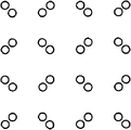
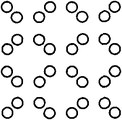
Fig. 9 is the partial enlarged drawing that has added the original image of low visual bar code.In typical case's use pattern of such a appended drawings picture, the small point of the information of presentation code is arranged on the whole original image.
Figure 10 is the figure that the example of the arrangement pattern of hanging down the point in the visual bar code is shown.Point 1003 shown in the black circle be fixed on virtual grid (by vertically and the clathrate pattern represented of horizontal straight line) intersection point (grid point) on anchor point.Point 1002 expressions shown in the Bai Yuan can be arranged the position by the data point of the direction of displacement that begins from grid point (direction of displacement of some position) expression information.In this example, around a grid point, specify 8 positions in advance, represent from 0 to 7 information according to the residing position of point.More particularly, any one position in position 0 to 7 forms point, and comes expression information by the position of point.As manifesting from Figure 10, when point 1002 expression information 1,3,4 and 6, data point 1002 is arranged on the virtual grid, and expression information 0,2,5 and 7 o'clock, data point 1002 was not arranged on the virtual grid.Constitute 100% being arranged on the virtual grid of 50% anchor point of some sum, about 50% (the expression information 1,3,4 and 6 situation) that constitutes 50% data point of some sum is arranged on the virtual grid.Therefore, the probability that is arranged in the quantity of the point on the virtual grid in the having a few (0.5 * 1+0.5 * 0.5=0.75) that is about 75%.In the present invention, by using the geometry characteristic,, also generate the downscaled images that easily to grasp the content of original document image even file and picture dwindles.
Next, the information analysis unit 131 that adds in the graphics processing unit 130 is described.
Figure 11 is the block diagram that the parts of configuration information analytic unit 131 are shown.131 detection/the analyses of information analysis unit are as the two-dimension code of appended drawings picture.
At first, some detecting unit 132 receives the image that is read by scanner unit 200 with the form of many-valued monochrome image.Embed by the name a person for a particular job information of appended drawings picture of two-value.Yet because the influence of the optical characteristics the when processing of the sheet material of the print characteristic when embedding, printing and scanning, the image that is read by scanner unit 200 is received with the state of putting trickle distortion.More particularly, because the offset of point and density unevenness are even, so information may be inaccurate.In order to eliminate these influences, by test point, and discern the position of the center of gravity of detected point as the absolute coordinate of each point, improve accuracy of detection.
Figure 12 is the figure of the detection method of the point in the explanation point detecting unit 132.
For test point, image is carried out the inspection of gap (gap) from four direction.The direction of the existence of Reference numeral 1201 to 1204 indication checkpoints whether the time.Normally about two pixels of the diameter of assumed position, for example, vertical 1201 testing result is " in vain ", " in vain ", " deceiving ", " deceiving ", " in vain " and " in vain ", can suppose that black part is a little.Yet only can not get rid of thus is the possibility of row (line) transversely.Similarly, though when only by checking horizontal 1202 when determining to be the possibility of point, also have the possibility of the row on being actually vertically.In the present embodiment, improve the inspection precision by the inspection of carrying out a little at longitudinal and transverse, right diagonal angle and left diagonal angle four direction.More particularly, exist on 1201 to 1204 all directions when being the testing result of possibility of point, determine to exist a little in this position when in a certain zone, having provided.
Next, be described in the details of the processing of carrying out in the point analysis unit 133.
According to definition, detected in a detecting unit 132 a bit needn't all be the point that constitutes low visual bar code.For example, such point can be the point of the half tone dot that comprises in the expression original image (file and picture), the voiced sound symbol of hiragana character etc.In the sparse processing of describing after a while, the such point that does not constitute low visual bar code can not be by sparse.Therefore, the point of expression half tone dot etc. need be removed from detected point.
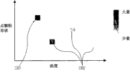
Figure 13 is used for illustrating the chart of removing the principle of the point that can not constitute low visual bar code from a detecting unit 132 detected points.
On axis of ordinates, mark and draw the grain shape of point, on axis of abscissas, marked and drawed the concentration of point, and shown the histogram of representing frequency a little with the concentration of point.Show histogrammic concentration high more (black more), the frequency of appearance is high more.Here, under the situation of the point of low visual bar code, when embedding, by making embed a little consistent with concentration of grain shape a little, so the peak of the frequency of occurrences appears at the close limit interior (1301) of chart.On the other hand, under the situation of the point of half tone dot etc., grain shape and concentration are not normalized, and therefore point sporadicly appears in the wide region on the chart.Therefore, frequency low relatively (1302).By using this characteristic, the position that the peak will be shown in close limit is defined as the point of low visual sign indicating number, and removes the point beyond this point.Absolute coordinate (positional information of each point on the absolute coordinate) at the point of the point that is defined as low visual sign indicating number is created the absolute coordinate tabulation, and with the absolute coordinate list storage in absolute coordinate list storage unit 134.
As mentioned above, by removing the processing of half tone dot etc., in the absolute coordinate tabulation, only print the point of low visual sign indicating number basically.
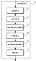
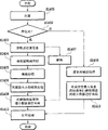
Figure 14 is the flow chart from the series of processing steps that scans type-script that illustrates according in the digital multi ancillary equipment 001 of present embodiment.Specifically, scan manuscript, the example of situation that analyze to embed the content of the additional information in the original copy and carry out the reporting printing of analysis result are described.
At first, in step S1401, scanner unit 200 based on via operating unit 400 from user's instruction (beginning to analyze the instruction of the operation of the information of embedding and reporting printing), the original copy that scanning is placed.To be input in the control unit 100 via scanner I/F 113 by the view data that scan manuscript obtains.To after the image execution predetermined process, in compression unit 112, view data is compressed, and it is stored among the RAM 107 temporarily in the scanner graphics processing unit 150 in control unit 100.Afterwards, in decompression unit 121, view data is decompressed, and be entered in the additional graphics processing unit 130.
In step S1402, the view data of the 132 pairs of inputs of some detecting unit in the additional graphics processing unit 130 is carried out above-mentioned point and is detected processing, determines whether exist a little in image.
When determining not exist, in step S1409, view data is carried out common convergent-divergent and handle.More particularly, will not exist definite result a little to report to CPU 103, and, the view data that temporarily is stored among the RAM 107 is input in the unit for scaling 124 via decompression unit 121 according to order from CPU 103 via system bus 101.In unit for scaling 124, view data is carried out common convergent-divergent handle, view data is dwindled into the size (for example 10% of length and width size) that is used for reporting printing, obtain downscaled images thus.
In step S1410, synthesis unit 128 is distributed in the character picture of the downscaled images that obtains and the no additional information of expression (for example " additional information of not having embedding " etc.) with in one page.More particularly, be created on an image arranging downscaled images and character picture in the presumptive area of one page.
On the other hand, when in step S1402, determining to have point, handle entering step S1403.
In step S1403, above-mentioned analyzing and processing is carried out in the point analysis unit 133 in the additional graphics processing unit 130, to generate and to print the absolute coordinate tabulation.More particularly, point analysis unit 133 obtains the positional information (coordinate) of the point that constitutes the appended drawings picture.
Subsequently, executed in parallel generates the processing (step S1404 is to step S1406) of downscaled images and the appended drawings of encoding is looked like to carry out process of decoding (step S1407).
At first, the processing that generates downscaled images is described.
In step S1404, sparse unit 129 is defined as wanting sparse row with reference to the absolute coordinate tabulation that generates with the row that has many points.Specifically, sparse unit 129 is along virtual grid each at stringer and in walking crosswise, and how many somes tabulation is calculated and be positioned on the row according to absolute coordinate, and will add up that the residing row of the many points in ground is defined as will sparse row.
Subsequently, in step S1405,129 pairs of sparse unit are determined from view data (being input to the view data in the additional graphics processing unit 130 among step S1402) in step S1404 wants the pixel of sparse row, carries out sparse processing.
Figure 15 A is the figure that the principle of sparse processing visually is described to Figure 15 D.
As also described in Figure 10, Reference numeral 1501 indications of Figure 15 A are arranged in the anchor point on the grid point of virtual grid, and Reference numeral 1502 indications can be arranged by represent the position of the data point of information from the offset of grid point.What Reference numeral 1503 indications were determined in step S1404 will sparse row.Corresponding to the size of point 1501 and 1502, determine the width of row 1503 that will be sparse.For example, measure and be formed in the size of the point of detected appended drawings picture in the point analysis unit, and ask it average.In addition, mean value be multiply by α (for example 1.1 times) etc., determine the width of row that will be sparse thus.Subsequently, remove the pixel of the row of wanting sparse from entire image, thus, the point that only is arranged in the data point place shown in Figure 15 C is residual.As a result, the output of the sparse processing among the step S1405 is the form shown in Figure 15 D.
By above-mentioned processing, generate formation and hang down the view data that the quantity of the point of visual bar code significantly reduces.To be input in the unit for scaling 124 through the view data of sparse processing.
In step S1406, unit for scaling 124 is carried out and view data is dwindled (or amplification) processing to the size that is used for reporting printing, and generates the image that has according to the pixel quantity of application target definition.As variable change times method, can the application of known method.For example, can use arest neighbors method (nearest neighbor method), two cubes of interpolation or Bilinear Method (bi-cubicinterpolation or bilinear method) etc., the arest neighbors method is applied directly to output image with the value of the necessary pixel of original image according to the quantity of necessary pixel, and the value of two cubes of interpolation or the Bilinear Method a plurality of pixels by using original image is carried out interpolation calculation and determined output pixel value.
Next, the appended drawings of describing coding looks like to carry out process of decoding.
In step S1407, additional graphics processing unit 130 is carried out the processing of each unit in converting unit 135, relative coordinate list storage unit 136 and the decoding unit 137 at above-mentioned, with the information (additional information) that obtains to embed.The information representation character code that embeds is carried out the processing that character code is converted to character picture at this, but this processing and the present invention do not have direct relation.Therefore, omit its details.
After finishing the processing that generates downscaled images as mentioned above and the appended drawings of coding looked like to carry out process of decoding, handle entering step S1408.
In step S1408, synthesis unit 128 will be used for reporting printing and the information (character picture) of the image that dwindles and embedding is assigned to the precalculated position with one page.More particularly, synthesis unit 128 generates the view data that the downscaled images that will generate is linked to the decoded result among the step S1407 in step S1406.
At last, in step S1411, printer unit 300 print execution the view data of layout processing.Specifically, view data is not through decompression unit 141 (because view data is compressed at first), in printer image processing unit 160, view data is converted to after the data that print, data are sent to printer unit 300 via printer I/F 115.Subsequently, printer unit 300 print image datas, thus finish series of processing steps.
In the present embodiment, the situation of printing the view data that generates has been described, but can with the image data storage that generates in HDD 109 grades so that use in the future.In this case, also represented the effect that the present invention can stably guarantee the visuality of the original original copy on the downscaled images.
Fig. 8 is the figure that the situation that use is printed the situation of the reporting printing with downscaled images and used the conventional art printed report to print according to the digital multi ancillary equipment of present embodiment is compared.Wherein there is the low visual bar code of being represented by the set of point in the original original copy of Reference numeral 801 indications in whole original copy.The reporting printing that the present invention prints is used in Reference numeral 802 indications, and the reporting printing that conventional art prints is used in Reference numeral 803 indications.When will be when dwindling thumbnail image 804 and 805 that original image 801 generates and compare, their difference comes into plain view.Increased the weight of owing to constitute the point of low visual bar code, so image 805 is whole shows black result, visual variation and be difficult to discern character and figure in the thumbnail image.On the other hand, sparse by the point that constitutes low visual bar code is carried out, use image 804 whole whitenings of the present invention, the result, in thumbnail image, image has character and the figure good contrast with respect to background, and image has good visuality.Therefore, can understand its content immediately.
In the present embodiment, described the situation of low visual bar code as example, but the invention is not restricted to this.Copy-forgery-inhibited pattern that the present invention can be widely used in describing after a while and N dimension sign indicating number are as long as it is the coding techniques that is made of the set of putting.Especially when point was arranged to the basic cycle property that has to a certain degree, it is remarkable that effect becomes.
[second embodiment]
In first embodiment,, the pattern that detected the point that constitutes low visual sign indicating number before point is carried out sparse processing has been described for the situation that adopts low visual bar code as the example of two-dimension code.In the present embodiment, for the situation that adopts copy-forgery-inhibited pattern as example, be described in point is carried out the pattern that sparse processing does not detect point before.
The part common with first embodiment adopts identical figure and Reference numeral, and omits its details.
At first, use Figure 16 and Figure 17 to describe the overview of copy-forgery-inhibited pattern.
Figure 16 is the example of having added the image of copy-forgery-inhibited pattern.Copy-forgery-inhibited pattern is characterised in that to make arranges that puncticulose zone is identical with the mean concentration that is furnished with a little bigger zone.Thus, form the image that is included in two kinds of zones that visually are difficult to distinguish, and when printed copy, the zone of point is not reproduced, thus, the character such as " COPY " can be apparent in the duplicating thing.
Figure 17 is the layout example of the point in the copy-forgery-inhibited pattern.In the zone that constitutes by point 1701 (left side), with than by a little bigger 1702 regional high concentration layout points that constitute.By layout points periodically as shown in figure 17, form many copy-forgery-inhibited patterns usually.In the present embodiment, utilize the feature of the periodic arrangement of point to realize dwindling method.
Figure 18 is the flow chart from the series of processing steps that scans type-script that illustrates according in the digital multi ancillary equipment 001 of present embodiment.
At first, in step S1801, scan manuscript.After in the additional graphics processing unit 130 of view data input, in step S1802, additional graphics processing unit 130 is analyzed copy-forgery-inhibited pattern by unshowned internal module (copy-forgery-inhibited pattern analytic unit), and determine to exist the probability of the point that constitutes copy-forgery-inhibited pattern high want sparse row.
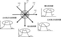
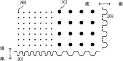
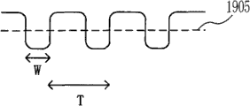
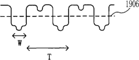
Figure 19 A is the figure of principle of the analyzing and processing of explanation copy-forgery-inhibited pattern to Figure 19 C.
As mentioned above, copy-forgery-inhibited pattern is made of two zones, and a zone is made of point 1901, and a zone constitutes by a little bigger 1902.In order to determine that simply these put residing row, accumulate pixel value respectively at a plurality of arranged direction (for example vertical and horizontal) that property dot cycle ground occurs, to obtain the Wave data 1903 and 1904 of the distribution that accumulated value is shown shown in Figure 19 A.Utilize the periodicity of Wave data to detect the row that has point in the entire image.For example, under the situation of the Wave data of Figure 19 B, the cycle that can determine an existence is T, and can determine that width a little is w.According to period T that obtains and some width w, determine the position and the width of row that will be sparse.In addition, under the situation of point and a little bigger row that coexists, obtain the Wave data shown in Figure 19 C.In the case, can use and exist point and a little bigger both part to obtain period T and width w as benchmark.Yet, in real image, also there is the some point in addition that constitutes copy-forgery-inhibited pattern, so the Wave data distortion.Therefore,, mean value (by the value shown in dotted line 1905 or 1906) is set to benchmark (threshold value), accumulated value is divided into above the part of benchmark and the part below the benchmark, and uses thus obtained Wave data for the waveform that obtains to be suitable for determining.
As mentioned above, try to achieve the position and the width of the high row of the probability of the point that exist to constitute copy-forgery-inhibited pattern, to determine to want sparse row.
In step S1803,129 pairs of sparse unit be stored in temporarily view data among the RAM 107 carry out in step S1802, determine want sparse stringer and the sparse processing of walking crosswise, and generate the view data of the point of having removed the formation copy-forgery-inhibited pattern.
The view data that generates is input in the unit for scaling 124, and is converted into desired images size (step S1804).
Subsequently, with identical in first embodiment, in step S1805, downscaled images is carried out layout at random.At this moment, can discern in order to make the copy-forgery-inhibited pattern that appends to raw image data, can be in the information of placed around such as the message (for example " original image comprises copy-forgery-inhibited pattern ") of downscaled images.In this case, for example, execution will illustrate the processing that the information of having added copy-forgery-inhibited pattern is incorporated the view data of generation into, and the information of having added copy-forgery-inhibited pattern and the processing that links as the view data of data separately maybe will be shown.Afterwards, in step S1806, use the view data that generates to carry out print processing.
In addition, identical with the situation of first embodiment, can be in HDD 109 grades with the image data storage that generates as mentioned above, so that use etc. in the future.
[other embodiment]
Each side of the present invention can also be by reading and executive logging is carried out the system of functional programs of the foregoing description or the computer of device (or such as CPU or MPU device) in being used on the memory device and come the method for execution in step to realize by the functional programs that the computer of system or device is for example read and executive logging being used on memory device carried out the foregoing description.Given this, for example provide program to computer via network or from various types of recording mediums (for example computer-readable medium) as memory device.
Though described the present invention with reference to exemplary embodiment, should be appreciated that to the invention is not restricted to disclosed exemplary embodiment.The scope of reply claims gives the most wide in range explanation, so that it covers all modification, equivalent structure and function.
Claims (7)
1. image processing apparatus, described image processing apparatus comprises:
Dwindle the unit, it is configured to downscaled images; And
Delete cells, it is configured to, comprise under the situation of the appended drawings picture with the information that is hidden in the appended drawings picture at described image when dwindling the unit and dwindling described image described, deletes described appended drawings picture.
2. image processing apparatus according to claim 1,
Wherein, described appended drawings picture constitutes by being arranged to the point with basic cycle property, and
Described delete cells is deleted described appended drawings picture by the pixel of the residing row of sparse described point from described image.
3. image processing apparatus according to claim 2, described image processing apparatus also comprises:
Acquiring unit, it is configured to obtain the positional information of the point that constitutes described appended drawings picture; And
Determining unit, it is configured to determine the residing row of described point based on the positional information of being obtained.
4. image processing apparatus according to claim 3, described image processing apparatus also comprises:
Remove the unit, it is configured to remove the point that can not constitute described appended drawings picture from described image.
5. image processing apparatus according to claim 2, described image processing apparatus also comprises:
In a plurality of arranged direction that are configured to occur at property dot cycle of described appended drawings picture ground each accumulated pixel value, with the unit of the distribution of obtaining accumulated value; And
Determining unit, it is configured to determine the residing row of described point according to the distribution of the accumulated value that is obtained.
6. image processing apparatus according to claim 1,
Wherein, described appended drawings similarly is copy-forgery-inhibited pattern or two-dimension code.
7. image processing method, described image processing method comprises:
Reduction process, downscaled images; And
The deletion step when dwindling described image in described reduction process, comprises under the situation of the appended drawings picture with the information that is hidden in the appended drawings picture at described image, deletes described appended drawings picture.
Applications Claiming Priority (2)
| Application Number | Priority Date | Filing Date | Title |
|---|---|---|---|
| JP2009018731A JP5159660B2 (en) | 2009-01-29 | 2009-01-29 | Image processing apparatus, image processing method, program for executing image processing method, and recording medium |
| JP2009-018731 | 2009-01-29 |
Publications (1)
| Publication Number | Publication Date |
|---|---|
| CN101795343A true CN101795343A (en) | 2010-08-04 |
Family
ID=42353939
Family Applications (1)
| Application Number | Title | Priority Date | Filing Date |
|---|---|---|---|
| CN201010106699A Pending CN101795343A (en) | 2009-01-29 | 2010-01-26 | Image processing apparatus and image processing method |
Country Status (3)
| Country | Link |
|---|---|
| US (1) | US20100188670A1 (en) |
| JP (1) | JP5159660B2 (en) |
| CN (1) | CN101795343A (en) |
Families Citing this family (2)
| Publication number | Priority date | Publication date | Assignee | Title |
|---|---|---|---|---|
| AU2007254595B2 (en) * | 2007-12-20 | 2011-04-07 | Canon Kabushiki Kaisha | Constellation detection |
| JP6194903B2 (en) * | 2015-01-23 | 2017-09-13 | コニカミノルタ株式会社 | Image processing apparatus and image processing method |
Citations (4)
| Publication number | Priority date | Publication date | Assignee | Title |
|---|---|---|---|---|
| US20070091352A1 (en) * | 2005-10-21 | 2007-04-26 | Canon Kabushiki Kaisha | Image processing apparatus and a control method therefor |
| US20080180753A1 (en) * | 2007-01-30 | 2008-07-31 | Oki Electric Industry Co., Ltd. | System for managing flexible copying with information leakage prevented and/or detected |
| JP2008271110A (en) * | 2007-04-19 | 2008-11-06 | Canon Inc | Image processor, its control method, control program, and storage medium |
| US20090010695A1 (en) * | 2003-10-10 | 2009-01-08 | Canon Kabushiki Kaisha | Information processing apparatus and information processing method |
Family Cites Families (12)
| Publication number | Priority date | Publication date | Assignee | Title |
|---|---|---|---|---|
| JP4029253B2 (en) * | 2000-04-10 | 2008-01-09 | 富士フイルム株式会社 | Image resizing apparatus and method |
| JP2003211727A (en) * | 2002-01-23 | 2003-07-29 | Canon Inc | Imaging apparatus and imaging method |
| US7339599B2 (en) * | 2003-01-22 | 2008-03-04 | Canon Kabushiki Kaisha | Image-processing apparatus and method, computer program, and computer-readable storage medium for discouraging illegal copying of images |
| JP4164463B2 (en) * | 2003-06-03 | 2008-10-15 | キヤノン株式会社 | Information processing apparatus and control method thereof |
| JP4259462B2 (en) * | 2004-12-15 | 2009-04-30 | 沖電気工業株式会社 | Image processing apparatus and image processing method |
| JP2007081692A (en) * | 2005-09-13 | 2007-03-29 | Canon Inc | Image forming apparatus and image forming apparatus particularizing system |
| JP4135012B2 (en) * | 2005-10-31 | 2008-08-20 | コニカミノルタビジネステクノロジーズ株式会社 | Image processing apparatus and image processing method |
| US20070127056A1 (en) * | 2005-12-06 | 2007-06-07 | Canon Kabushiki Kaisha | Image processing apparatus, image processing method and program, and storage medium therefor |
| JP4865475B2 (en) * | 2006-09-25 | 2012-02-01 | 株式会社リコー | Image display data generation system, image display data generation method, and image display data generation program |
| JP2008160675A (en) * | 2006-12-26 | 2008-07-10 | Fuji Xerox Co Ltd | Image generator, copy controller, program and printing medium |
| JP4314282B2 (en) * | 2007-03-07 | 2009-08-12 | キヤノン株式会社 | Authentication apparatus, image processing apparatus, control method for image processing apparatus, program, and storage medium |
| JP4448156B2 (en) * | 2007-07-05 | 2010-04-07 | キヤノン株式会社 | Apparatus, method and program |
-
2009
- 2009-01-29 JP JP2009018731A patent/JP5159660B2/en not_active Expired - Fee Related
-
2010
- 2010-01-15 US US12/688,304 patent/US20100188670A1/en not_active Abandoned
- 2010-01-26 CN CN201010106699A patent/CN101795343A/en active Pending
Patent Citations (4)
| Publication number | Priority date | Publication date | Assignee | Title |
|---|---|---|---|---|
| US20090010695A1 (en) * | 2003-10-10 | 2009-01-08 | Canon Kabushiki Kaisha | Information processing apparatus and information processing method |
| US20070091352A1 (en) * | 2005-10-21 | 2007-04-26 | Canon Kabushiki Kaisha | Image processing apparatus and a control method therefor |
| US20080180753A1 (en) * | 2007-01-30 | 2008-07-31 | Oki Electric Industry Co., Ltd. | System for managing flexible copying with information leakage prevented and/or detected |
| JP2008271110A (en) * | 2007-04-19 | 2008-11-06 | Canon Inc | Image processor, its control method, control program, and storage medium |
Also Published As
| Publication number | Publication date |
|---|---|
| JP2010178084A (en) | 2010-08-12 |
| US20100188670A1 (en) | 2010-07-29 |
| JP5159660B2 (en) | 2013-03-06 |
Similar Documents
| Publication | Publication Date | Title |
|---|---|---|
| JP4218920B2 (en) | Image processing apparatus, image processing method, and storage medium | |
| US7599099B2 (en) | Image processing apparatus and image processing method | |
| JP3813387B2 (en) | Information embedding method and apparatus, and recording medium | |
| JP4732250B2 (en) | Information processing apparatus, control method, and computer program | |
| CN101800827B (en) | Apparatus and method | |
| US8335014B2 (en) | Image forming apparatus, control method, and program for copy-forgery-inhibited dot pattern calibration | |
| JP5312166B2 (en) | Image processing apparatus, control method, and program | |
| CN101867673B (en) | Image processing apparatus and image processing method | |
| US8280100B2 (en) | Image processing apparatus, image processing method, and computer program product | |
| CN101581909B (en) | Image processing apparatus handling copy-forgery-inhibited pattern image data | |
| JP4771283B2 (en) | Image processing apparatus, image forming apparatus, copy-forgery-inhibited pattern image, printed matter, image processing method, image forming method, and program | |
| US8170275B2 (en) | Determining document authenticity in a closed-loop process | |
| US7372594B1 (en) | Image processing apparatus and method, and storage medium | |
| US20140092442A1 (en) | Image processing apparatus and image processing method | |
| Mizumoto et al. | Robustness investigation of DCT digital watermark for printing and scanning | |
| JP4380733B2 (en) | Apparatus and method for managing copy history of manuscript | |
| JP2011193394A (en) | Image processing apparatus, image processing method, and program | |
| JP3514050B2 (en) | Image processing device | |
| CN101465939B (en) | Image processing apparatus, image processing method | |
| US8274515B2 (en) | Vector image generation method, image processing apparatus, and computer-readable storage medium for computer program | |
| CN101795343A (en) | Image processing apparatus and image processing method | |
| JP2001313814A (en) | Image processor, image-processing method and storage medium | |
| CN101207693B (en) | Image forming apparatus, image forming device control method | |
| JP5538996B2 (en) | Image processing apparatus, image processing method, program, and storage medium | |
| JP2010206399A (en) | Image processing apparatus, method and program |
Legal Events
| Date | Code | Title | Description |
|---|---|---|---|
| C06 | Publication | ||
| PB01 | Publication | ||
| C10 | Entry into substantive examination | ||
| SE01 | Entry into force of request for substantive examination | ||
| C12 | Rejection of a patent application after its publication | ||
| RJ01 | Rejection of invention patent application after publication |
Application publication date: 20100804 |