CN101795022A - Equipment and method to external device (ED) supply electric power - Google Patents
Equipment and method to external device (ED) supply electric power Download PDFInfo
- Publication number
- CN101795022A CN101795022A CN201010106079A CN201010106079A CN101795022A CN 101795022 A CN101795022 A CN 101795022A CN 201010106079 A CN201010106079 A CN 201010106079A CN 201010106079 A CN201010106079 A CN 201010106079A CN 101795022 A CN101795022 A CN 101795022A
- Authority
- CN
- China
- Prior art keywords
- electric power
- unit
- external device
- power supply
- charging
- Prior art date
- Legal status (The legal status is an assumption and is not a legal conclusion. Google has not performed a legal analysis and makes no representation as to the accuracy of the status listed.)
- Pending
Links
Images


Classifications
-
- H—ELECTRICITY
- H02—GENERATION; CONVERSION OR DISTRIBUTION OF ELECTRIC POWER
- H02J—CIRCUIT ARRANGEMENTS OR SYSTEMS FOR SUPPLYING OR DISTRIBUTING ELECTRIC POWER; SYSTEMS FOR STORING ELECTRIC ENERGY
- H02J50/00—Circuit arrangements or systems for wireless supply or distribution of electric power
- H02J50/40—Circuit arrangements or systems for wireless supply or distribution of electric power using two or more transmitting or receiving devices
- H02J50/402—Circuit arrangements or systems for wireless supply or distribution of electric power using two or more transmitting or receiving devices the two or more transmitting or the two or more receiving devices being integrated in the same unit, e.g. power mats with several coils or antennas with several sub-antennas
-
- H—ELECTRICITY
- H02—GENERATION; CONVERSION OR DISTRIBUTION OF ELECTRIC POWER
- H02J—CIRCUIT ARRANGEMENTS OR SYSTEMS FOR SUPPLYING OR DISTRIBUTING ELECTRIC POWER; SYSTEMS FOR STORING ELECTRIC ENERGY
- H02J50/00—Circuit arrangements or systems for wireless supply or distribution of electric power
- H02J50/10—Circuit arrangements or systems for wireless supply or distribution of electric power using inductive coupling
-
- H—ELECTRICITY
- H02—GENERATION; CONVERSION OR DISTRIBUTION OF ELECTRIC POWER
- H02J—CIRCUIT ARRANGEMENTS OR SYSTEMS FOR SUPPLYING OR DISTRIBUTING ELECTRIC POWER; SYSTEMS FOR STORING ELECTRIC ENERGY
- H02J50/00—Circuit arrangements or systems for wireless supply or distribution of electric power
- H02J50/80—Circuit arrangements or systems for wireless supply or distribution of electric power involving the exchange of data, concerning supply or distribution of electric power, between transmitting devices and receiving devices
-
- H—ELECTRICITY
- H02—GENERATION; CONVERSION OR DISTRIBUTION OF ELECTRIC POWER
- H02J—CIRCUIT ARRANGEMENTS OR SYSTEMS FOR SUPPLYING OR DISTRIBUTING ELECTRIC POWER; SYSTEMS FOR STORING ELECTRIC ENERGY
- H02J50/00—Circuit arrangements or systems for wireless supply or distribution of electric power
- H02J50/90—Circuit arrangements or systems for wireless supply or distribution of electric power involving detection or optimisation of position, e.g. alignment
-
- H—ELECTRICITY
- H02—GENERATION; CONVERSION OR DISTRIBUTION OF ELECTRIC POWER
- H02J—CIRCUIT ARRANGEMENTS OR SYSTEMS FOR SUPPLYING OR DISTRIBUTING ELECTRIC POWER; SYSTEMS FOR STORING ELECTRIC ENERGY
- H02J7/00—Circuit arrangements for charging or depolarising batteries or for supplying loads from batteries
- H02J7/0013—Circuit arrangements for charging or depolarising batteries or for supplying loads from batteries acting upon several batteries simultaneously or sequentially
-
- H—ELECTRICITY
- H02—GENERATION; CONVERSION OR DISTRIBUTION OF ELECTRIC POWER
- H02J—CIRCUIT ARRANGEMENTS OR SYSTEMS FOR SUPPLYING OR DISTRIBUTING ELECTRIC POWER; SYSTEMS FOR STORING ELECTRIC ENERGY
- H02J7/00—Circuit arrangements for charging or depolarising batteries or for supplying loads from batteries
- H02J7/0047—Circuit arrangements for charging or depolarising batteries or for supplying loads from batteries with monitoring or indicating devices or circuits
- H02J7/0048—Detection of remaining charge capacity or state of charge [SOC]
-
- H—ELECTRICITY
- H02—GENERATION; CONVERSION OR DISTRIBUTION OF ELECTRIC POWER
- H02J—CIRCUIT ARRANGEMENTS OR SYSTEMS FOR SUPPLYING OR DISTRIBUTING ELECTRIC POWER; SYSTEMS FOR STORING ELECTRIC ENERGY
- H02J7/00—Circuit arrangements for charging or depolarising batteries or for supplying loads from batteries
- H02J7/00032—Circuit arrangements for charging or depolarising batteries or for supplying loads from batteries characterised by data exchange
- H02J7/00036—Charger exchanging data with battery
-
- H—ELECTRICITY
- H02—GENERATION; CONVERSION OR DISTRIBUTION OF ELECTRIC POWER
- H02J—CIRCUIT ARRANGEMENTS OR SYSTEMS FOR SUPPLYING OR DISTRIBUTING ELECTRIC POWER; SYSTEMS FOR STORING ELECTRIC ENERGY
- H02J7/00—Circuit arrangements for charging or depolarising batteries or for supplying loads from batteries
- H02J7/00047—Circuit arrangements for charging or depolarising batteries or for supplying loads from batteries with provisions for charging different types of batteries
-
- H—ELECTRICITY
- H02—GENERATION; CONVERSION OR DISTRIBUTION OF ELECTRIC POWER
- H02J—CIRCUIT ARRANGEMENTS OR SYSTEMS FOR SUPPLYING OR DISTRIBUTING ELECTRIC POWER; SYSTEMS FOR STORING ELECTRIC ENERGY
- H02J7/00—Circuit arrangements for charging or depolarising batteries or for supplying loads from batteries
- H02J7/0042—Circuit arrangements for charging or depolarising batteries or for supplying loads from batteries characterised by the mechanical construction
- H02J7/0044—Circuit arrangements for charging or depolarising batteries or for supplying loads from batteries characterised by the mechanical construction specially adapted for holding portable devices containing batteries
Landscapes
- Engineering & Computer Science (AREA)
- Power Engineering (AREA)
- Computer Networks & Wireless Communication (AREA)
- Charge And Discharge Circuits For Batteries Or The Like (AREA)
Abstract
The invention provides a kind of equipment and method to external device (ED) supply electric power.This equipment comprises: a plurality of electric power supply units are used in the noncontact mode to described a plurality of external device (ED) supply electric power; Acquiring unit is used to obtain the information relevant with the electric power accepting state, and whether each external device (ED) in the described a plurality of external device (ED)s of described information representation is receiving electric power; And recognition unit, be used for based on the described information of being obtained, discern the external device (ED) that each electric power supply unit in described a plurality of electric power supply unit supplies power to.
Description
Technical field
The present invention relates to a kind of equipment and method that is used to supply electric power.
Background technology
As the equipment that is used for to external device (ED) supply electric power, known a kind of electromagnetic induction that uses is with the charging device of noncontact mode to the external device (ED) charging.Mechanism below non-contact charge equipment uses is charged: change the voltage that (excitation) is applied to the primary coil of charging device, with the magnetic flux around the secondary coil that changes the charging destination apparatus, thereby make secondary coil generate electromotive force (for example, with reference to Japanese kokai publication hei 10-233235 communique).
This class non-contact charge equipment is mainly used in device chargings such as the electric shaver that may be got wet and electric toothbrushes.
Different with traditional charging method, the non-contact charge method has been eliminated the step that is used to make the terminal contact or connects the charging destination apparatus by cable.For this reason, the non-contact charge method has been proposed in various types of devices.
If can charge to various types of devices in the noncontact mode as mentioned above, then can expect such system, in this system, single charging device is equipped with a plurality of primary coils simultaneously multiple arrangement is charged.
If simultaneously to the multiple arrangement charging, then each primary coil charges to different device simultaneously in the noncontact mode.If the characteristic of employed battery and circuit is different between device, then importantly at primary coil identification charging destination apparatus, with to the suitable electric power of this device provisioning.
Summary of the invention
In one aspect of the invention, provide a kind of equipment that is used for to a plurality of external device (ED) supply electric power with battery, having comprised: a plurality of electric power supply units are used in the noncontact mode to described a plurality of external device (ED) supply electric power; Acquiring unit is used to obtain the information relevant with the electric power accepting state, and whether each external device (ED) in the described a plurality of external device (ED)s of described information representation is receiving electric power; And recognition unit, be used for based on the described information of being obtained, discern the external device (ED) that each electric power supply unit in described a plurality of electric power supply unit supplies power to.
In another aspect of this invention, a kind of equipment that is used for to the external device (ED) supply electric power with battery is provided, comprise: a plurality of electric power supply units, be used in the noncontact mode to described external device (ED) supply electric power, wherein, described external device (ED) be configured in the corresponding a plurality of presumptive areas of described a plurality of electric power supply units in; Recognition unit is used to discern described external device (ED); Display unit is used to show and the relevant information of a plurality of external device (ED)s that identifies; And control unit, be used to control a plurality of external device (ED)s that identify, between a plurality of external device (ED)s that identify, to transmit data.
In still another aspect of the invention, provide a kind of method that is used for to a plurality of external device (ED) supply electric power, having comprised: supply electric power in the noncontact mode to described a plurality of external device (ED)s by a plurality of electric power supply units with battery; Obtain the information relevant with the electric power accepting state by acquiring unit, whether each external device (ED) in the described a plurality of external device (ED)s of described information representation is receiving electric power; And the external device (ED) that supplies power to based on each electric power supply unit in the described a plurality of electric power supply units of the described information Recognition of being obtained by recognition unit.
By below with reference to the detailed description of accompanying drawing to exemplary embodiments, further feature of the present invention and aspect will be apparent.
Description of drawings
Be included in the specification and constitute the accompanying drawing of the part of specification, exemplary embodiments of the present invention, feature and aspect are shown, and are used for explaining principle of the present invention with specification.
Fig. 1 illustrates the charging system of the exemplary embodiments according to the present invention;
Fig. 2 A is the block diagram that the structure of charging device is shown;
Fig. 2 B is the block diagram that the structure of charging destination apparatus is shown;
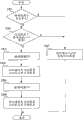
Fig. 3 is the flow chart that the processing that is used to discern the charging destination apparatus is shown;
Fig. 4 illustrates the charging system of the exemplary embodiments according to the present invention;
Fig. 5 is the flow chart that the processing that is used to discern the charging destination apparatus is shown;
Fig. 6 is the flow chart that the processing that is used to discern the charging destination apparatus is shown;
Fig. 7 illustrates mode signal;
Fig. 8 illustrates mode signal;
Fig. 9 A is the block diagram that the structure of charging device is shown;
Fig. 9 B is the block diagram that the structure of charging destination apparatus is shown;
Figure 10 is the flow chart that the processing that is used to discern the charging destination apparatus is shown;
Figure 11 is the block diagram that the structure of charging destination apparatus is shown;
Figure 12 is the flow chart that the processing that is used to discern the charging destination apparatus is shown;
Figure 13 illustrates the charging system of the exemplary embodiments according to the present invention;
Figure 14 is the block diagram that the structure of charging device is shown;
Figure 15 is the flow chart that the processing that is used to discern the charging destination apparatus is shown;
Figure 16 illustrates the charging system of the exemplary embodiments according to the present invention;
Figure 17 is the block diagram that the structure of charging device is shown;
Figure 18 illustrates the display frame of charging device; And
Figure 19 is the flow chart that the operation of charging device is shown.
Embodiment
Describe various exemplary embodiments of the present invention, feature and aspect in detail below with reference to accompanying drawing.
Fig. 1 illustrates the structure of the charging system 100 of first exemplary embodiments according to the present invention.Charging system 100 comprises charging device 200 and charging destination apparatus 300.Charging device 200 uses electromagnetic induction to supply electric power in the noncontact mode to charging destination apparatus 300.Charging destination apparatus 300 is the external device (ED)s with battery, and receives the electric power supplied from charging device 200 with to this battery charge.Charging device 200 is tabular, and charging destination apparatus 300 can be placed on the charging device 200.Charging device 200 comprises and is used for supplying electric power with the coil to 300 chargings of charging destination apparatus in the noncontact mode.Charging destination apparatus 300 be placed in charging device 200 on the corresponding charhing unit 201A of coil and 202A that are comprised, so that can be to the battery charge that is comprised in the charging destination apparatus 300.
Fig. 1 illustrates portable phone 300A and digital camera 300B as charging destination apparatus 300, yet the present invention can be applicable to described other device that can communicate by letter with charging device 200 in back.
Fig. 2 A is the block diagram that the structure of charging device 200 is shown.Fig. 2 B is the block diagram that the structure of charging destination apparatus 300 is shown.
Attaching plug 214 in the charging device 200 is connected with wall socket, to supply the AC voltages to rectification and smoothing circuit 203.Rectification and smoothing circuit 203 rectifications and the level and smooth AC voltage of supplying converting thereof into dc voltage, and are supplied to DC-DC transducer 204 with this dc voltage.DC-DC transducer 204 converts the dc voltage of input to predetermined voltage, and sends it to control unit 205.Control unit 205 comprises microcomputer and memory, and each unit in the control charging device 200.Control unit 205 control coil exciting units 206 and 207 are to use the dc voltage excitation coil 201 and 202 that sends from DC-DC transducer 204. Coil stimulating unit 206 and 207 based on the dc voltage excitation coil of being supplied from DC-DC transducer 204 201 and 202, with change magnetic flux, thereby is supplied electric power in the noncontact mode to charging destination apparatus 300 by control unit 205.
But but these functions make communication unit 210 to send information and to receive information from the outside communicator to the outside communicator.Communication unit 210 uses known communication techniques such as bluetooth, WLAN or Wi-Fi to carry out radio communication.
On the other hand, charging destination apparatus 300 is placed on the charhing unit 201A and 201B of charging device 200, so that electric current is because coil 201 and 202 magnetic flux that generated and flow in the coil 301 of secondary coil.Owing to the spread of voltage of being supplied from coil 301, thereby by rectification and smooth unit 302 rectifications and level and smooth this voltage, it is supplied to power control unit 303.Power control unit 303 charges to secondary cell 304 by the voltage that comes the sliding unit 302 of self-rectifying peace.Voltage and the charging interval state that detect secondary cell 304 of power control unit 303 by secondary cell 304 controlled supply of electric power to secondary cell.For example, can use lithium ion battery or Ni-MH battery as secondary cell 304.Secondary cell 304 can be assembled to charging destination apparatus 300 or unload secondary cell 304 from charging destination apparatus 300.
Fig. 2 B only illustrates according to the piece relevant with charging process in the charging destination apparatus 300 of this exemplary embodiments.As shown in Figure 1, for example,, then except that the structure shown in Fig. 2 B, also be provided for realizing other functional block of the function of portable phone if charging destination apparatus 300 is portable phone 300A.In addition, in digital camera 300B, and be similar to the charging destination apparatus 300 shown in Fig. 2 B according to the relevant processing block of the charging process of this exemplary embodiments.Except that the structure shown in Fig. 2 B, digital camera 300B also has the functional block of the function that is used to realize digital camera.
The processing that is used to discern charging destination apparatus 300 below with reference to the flowchart text charging device of Fig. 3.Processing by control unit 205 execution graphs 3.The not special assembling mains switch of the charging device 200 of Fig. 1.Attaching plug 214 is inserted wall socket, then automatic opening power.
When opening the power supply of charging device 200, detecting unit 208 magnetic test coils 201 and 202 voltage or the variation of electric current, and notify this variation to control unit 205.When on control unit 205 detects in charhing unit 201A and 201B at least one, having placed object, begin this handling process.
If on the charhing unit 201A of charging device 200 and 201B, placed objects such as charging destination apparatus, then with its on do not place anything and compare, coil 201 and 202 inductance more or less change.Control unit 205 makes coil stimulating unit 206 and 207 with predetermined period short time excitation coil 201 and 202.At this moment, the electric current that flows in detecting unit 208 magnetic test coils 201 and 202 is to detect variation inductance.Above-mentioned processing makes it possible to detect the objects such as charging destination apparatus that are placed on charhing unit 201A and the 201B.
At step S301, control unit 205 judges whether only to have placed object on a charhing unit.If only placed object (step S301 is a "Yes") on a charhing unit, then at step S307, communication unit 210 is communicated by letter with this object.If the object of placing is a charging destination apparatus 300, then communication unit 210 inquiry charging destination apparatus 300 it be the device of what kind.Communication unit 210 based in response to this inquiry from replying of being sent of charging destination apparatus 300, obtain the information relevant with the destination apparatus 300 of charging.Control unit 205 is based on the information Recognition charging destination apparatus 300 that obtains from communication unit 210.
In this exemplary embodiments, as the information of charging destination apparatus 300, the information of the charging capacity of acquisition battery and maximum charging voltage etc.Control unit 205 is according to the information that is obtained by communication unit 210, in the control coil exciting unit 206 and 207 with its on placed the corresponding coil stimulating of the charhing unit unit of charging destination apparatus, with transmission be suitable for the charging electric power of destination apparatus.
On the other hand, if control unit 205 is judged and all placed object (step S301 is a "No") on charhing unit 201A and 201B, then at step S302, control unit 205 judges whether to have identified and is placed in a charging destination apparatus on the charhing unit.
For example, then another object is placed on another charhing unit, then identified the charging destination apparatus of first placement if the destination apparatus that will charge earlier places on the charhing unit.(step S302 is a "Yes") in this case handles and enter step S307, and communication unit 210 communicated by letter with this device.If placed two charging destination apparatus, then communication unit 210 receives replying from these two charging destination apparatus 300.Yet, owing to identified a charging destination apparatus 300, thereby the destination apparatus 300 that another can be charged is identified as the device of new placement.Therefore, can discern the destination apparatus 300 that respectively charges that is placed on these two charhing unit 201A and the 201B.
If do not identify any device (step S302 is a "No"), then at step S303, at first excitation coil 201, and stop excitation coil 202.At step S304, communication unit 210 is communicated by letter with device, whether receives electric power with interrogation winding 301.At this moment, communication unit 210 receives replying from two charging destination apparatus 300.Because excitation coil 201 only, thereby obviously, notifying its device that is receiving electric power is that coil 201 transmits the device of electric power to it.For this reason, can will notify its device that is receiving electric power to be identified as the device that is placed on the charhing unit 201A.
At step S305, excitation coil 202, and stop excitation coil 201.At step S306, communication unit 210 communicate by letter with charging destination apparatus 300, with inquiry charge destination apparatus 300 they whether receiving electric power.As mentioned above, notifying its device that is receiving electric power is that coil 202 transmits the device of electric power to it, thereby can discern the device that is placed on the charhing unit 201B.
Therefore, when finishing the identification of the charging destination apparatus that is placed on each charhing unit, control unit 205 begins to be used for each is installed the processing of charging.Control unit 205 is according to the information Control coil stimulating unit 206 and 207 that is obtained by communication unit 210, is suitable for electric power to each charging destination apparatus charging with transmission.
More than explanation is for the explanation that is used for discerning in the system that comprises a charging device 200 and two charge destination apparatus 300A and 300B as shown in Figure 1 the processing of charging destination apparatus.
For example, may there be situation shown in the charging system 100A among Fig. 4.In Fig. 4, except that charging device 200, portable phone 300A and digital camera 300B, also there be charging device 200A, portable phone 300C and 300E and the video camera 300D of similar in charging device 200.
If device 300C~300E be present in charging device 200 can with scope that these devices are communicated by letter in, then as described in Figure 3, equipment 300C~300E is to replying from the inquiry of communication unit 210.In addition, if just by charging device 200A to portable phone 300C and video camera 300D charging, then portable phone 300C and video camera 300D send replying that they just are being recharged.As a result, in can not recognition device 300A~300D which is placed on the charging device 200.
Therefore, in this exemplary embodiments, carry out identification according to the flow chart of Fig. 5 and handle, be placed in charging destination apparatus on the charging device 200 with identification.Processing by control unit 205 execution graphs 5.
When detecting unit 208 detects the variation of the voltage or the electric current of coil 201 and 202, and control unit 205 detects when having placed the charging destination apparatus in charhing unit 201A and 201B at least one, begins this handling process.
At step S501, whether control unit 205 exists the charging destination apparatus that can communicate by letter with communication unit 210 around judging.If there is not the charging destination apparatus (step S501 is a "No") that can communicate by letter on every side, then judging the device that is placed on the charging device 200 is not the charging destination apparatus, and finishes this processing.
At step S502, if the charging destination apparatus responds (step S501 is a "Yes") to this inquiry, then at step S502, control unit 205 judges whether to exist function class to be similar to the charging device of charging device 200 based on replying that communication unit 210 is received.If control unit 205 detects charging device, for example, the charging device 200A (step S502 is a "Yes") on every side among Fig. 4, then at step S503, the on-off mode adjustment of between charging device, charging.
The following describes charging on-off mode adjustment.
After detecting charging device, between charging device, adjust, to prevent that detecting the employed mode signal of the device that is placed on the charging device 200 in the described in the back processing repeats.In this case, carry out this adjustment, so that charging device 200 uses mode signal 701 shown in Figure 7, and charging device 200A uses mode signal 702 shown in Figure 7.
If there is no function class is similar to the charging device (step S502 is a "No") of charging device 200, then charging device 200 uses suitable mode signal 801 as shown in Figure 8.In Fig. 7 and 8, when signal becomes on, excitation coil 201 and 202.When signal becomes off, stop excitation coil 201 and 202.
At step S504, communication unit 210 beginnings are communicated by letter with the destination apparatus that charges around all.In Fig. 4, charging device 200 is communicated by letter with portable phone 300A, digital camera 300B, portable phone 300C, video camera 300D and portable phone 300E.At step S505, carry out the processing that is used to judge the device of being placed.
The processing that is used to judge the device of being placed below with reference to the flowchart text step S505 of Fig. 6.
At step S601, control unit 205 is according to mode signal, for example by the signal 701 among determined Fig. 7 of processing of step S503, and control coil exciting unit 206 and 207, thereby switching coil 201 and 202 energized condition in the same manner.Each mode signal is stored in the memory (not shown).As shown in Figure 7, mode signal 701 switches between on state and off state with the predetermined period of t0~t4.For example, mode signal 701 during t0 be off, thereby stop excitation coil 201 and 202 both.At step S602, whether the charging destination apparatus that communication unit 210 inquiries are being communicated by letter it receiving electric power.For example, at Fig. 4, owing to stop excitation coil 201 and 202, thereby portable phone 300A and digital camera 300B send them and are not receiving replying of electric power.On the other hand, owing to control the charging process of portable phone 300C and video camera 300D by charging device 200A, thereby do not know whether portable phone 300C and video camera 300D send them and receiving replying of electric power.To portable phone 300E charging, thereby portable phone 300E sends it and is not receiving replying of electric power.
At this moment, finish processing during of mode signal.At step S603, control unit 205 judges whether to have finished the processing of t0~t4 during all.Because the processing of t0 during only having finished this moment, thus the term of execution t1 processing.During t1 excitation coil 201 and 202.Communication unit 210 is inquired the charging destination apparatus once more.
Therefore, repeat to switch energized condition and inquire each device according to mode signal about receiving electric power.Charging device 200 and 200A according to the mode signal 701 and 702 of Fig. 7, switch energized condition and inquiry charging destination apparatus with same period respectively.In this case, even each charging device carries out the processing of step S601 and S602 simultaneously, portable phone 300C and video camera 300D also return replying of the energized condition that is different from charging device 200 during Fig. 7 in t0~t4.Therefore, can judge portable phone 300C and video camera 300D is not placed on the charging device 200.If use the mode signal of Fig. 8, then during repeat same treatment in t0~t7.
At step S604, (step S601~S603) can judge portable phone 300A and digital camera 300B is the charging destination apparatus that is placed on the charging device 200 by above-mentioned processing.
Therefore determine to be placed in the device on the charging device 200, the processing of control unit 205 execution in step S506 and later step then.Step S506~S512 is identical with the processing of step S301~S307 of Fig. 3, thereby omits the explanation to it.
In this exemplary embodiments, between two charging devices 200 and 200A, adjust overlapped to prevent mode signal.Yet, replacing the adjustment modes signal, mode signal can use and for example be difficult to long mode signal shown in Figure 8 of overlapping random number or cycle.
In this exemplary embodiments,, when charging device has three or more charhing units, can discern the charging destination apparatus that is placed on each charhing unit similarly although the charging device with two charhing units has been described.
In the processing of Fig. 5 and 6, at first determine to be placed in the charging destination apparatus on the charging device 200, identification is placed in the charging destination apparatus on each charhing unit then.Yet, in Fig. 6, replace by encouraging two coils to inquire simultaneously, can carry out inquiry by only encourage a coil according to mode signal to the electric power accepting state.
More specifically, in the processing of step S601, for example,, and keep stopping excitation coil 202 according to mode signal excitation coil 201.Result as at each device of electric power accepting state inquiry can be identified as the device that is placed on the charhing unit 210A with carrying out the following device of replying: according to the energized condition of mode signal corresponding to the electric power accepting state.Control coil 202 in the same manner, thereby make and can discern the device that is placed on the charhing unit 202A.
In this case, do not carry out the processing of step S506 and later step.
According to this exemplary embodiments, can discern the charging destination apparatus that is placed on a plurality of charhing units.According to the information Control that is received from each device and the energized condition of the corresponding coil of a plurality of charhing units, so that can be to the best electric power of each device provisioning.
In first exemplary embodiments, be placed in device on the charging device 200 with identification according to the energized condition of mode signal control coil.On the other hand, in this exemplary embodiments, for the control signal of coil stimulating unit, the multiplexing modes signal is with excitation coil.
Fig. 9 A is the block diagram of structure that the charging device 200 of the charging system 100 in this exemplary embodiments is shown, and Fig. 9 B is the block diagram of structure that the charging destination apparatus 300A of the charging system 100 in this exemplary embodiments is shown.Represent the assembly identical with 2B with same reference numerals, and omit detailed description thereof with Fig. 2 A.
In Fig. 9 A, 215 pairs of coil stimulating unit 206, the multiplexed unit of signal and 207 the multiplexed signal specific of signal.In Fig. 9 B, signal separation unit 310 is isolated the signal specific composition from the excitation energy that sends from coil 301, and sends it to communication control unit 308.
Be used to discern the processing of charging destination apparatus in this exemplary embodiments of flowchart text below with reference to Figure 10.In Figure 10, step S1001~S1004 is identical with the processing of step S501~S504, thereby omits the explanation to it.
As mentioned above, charging device 200 carries out the charge mode adjustment with other charging device, and beginning communicates with the destination apparatus that charges.After this, at step S1005, for example, to the mode signal 701 of multiplexed Fig. 7 of control signal of coil stimulating unit 206 with excitation coil 201.The signal separation unit 310 of charging in the destination apparatus 300 be from the output clastotype signal of coil 301, and export it to communication control unit 308.
At step S1006, communication unit 210 each device of request send it back detected pattern.In this case, portable phone 300A can send it back mode signal 701, thereby can learn that the charging destination apparatus that is placed on the charhing unit 201A is portable phone 300A.
At step S1007 and S1008, coil 202 is carried out similar processing.As a result, can learn that the charging destination apparatus that is placed on the charhing unit 202A is digital camera 300B.
Therefore, according to this exemplary embodiments, can discern the charging destination apparatus that is placed on a plurality of charhing units.According to energized condition from the information Control coil of each device, thus can be to the best electric power of each device provisioning.
According to the 3rd exemplary embodiments, the charging destination apparatus can excitation coil.Figure 11 is the block diagram that illustrates according to the structure of the charging destination apparatus 300 of the 3rd exemplary embodiments.Represent the assembly identical with same reference numerals, and omit detailed description thereof with Fig. 2 B.Figure 11 has added coil stimulating unit 311 with different being of Fig. 2 B to charging destination apparatus 300.The structure of the charging device in the 3rd exemplary embodiments is identical with the structure of the charging device 200 shown in Fig. 2 A.Omit detailed description thereof.
When from charging device 200 during to the communication unit 305 request excitation coils of charging the destination apparatus 300, communication control unit 308 control coil exciting units 311 are at scheduled period underexcitation coil 301.If charging destination apparatus 300 is placed on the charging device 200, then, in coil 201 or 202, generate electromotive force according to the excitation operation of the 311 pairs of coils 301 in coil stimulating unit.
Below with reference to the processing that is used to discern the charging destination apparatus of the flowchart text of Figure 12 according to this exemplary embodiments.Step S1201 among Figure 12, S1202 and S1206 are identical with the processing of step S301, the S302 of Fig. 3 and S307 respectively.
At step S1201, control unit 205 judges whether only to have placed object on a charhing unit.If only placed object (step S1201 is a "Yes") on a charhing unit, then at step S1206, communication unit 210 is communicated by letter with this object with identification charging destination apparatus.
All placed object (step S1201 is a "No") if control unit 205 is judged on charhing unit 201A and 201B, then at step S1202, control unit 205 judges whether to have identified the charging destination apparatus that is placed on one of them charhing unit.If identified the charging destination apparatus (step S1202 is a "Yes") that is placed on one of them charhing unit, then handle and enter step S1206, and communication unit 210 is communicated by letter with object to discern the charging destination apparatus of new placement.
If do not identify any device (step S1202 is a "No"), then at step S1203, any in a plurality of charging destination apparatus that communication unit 210 is selected just communicating by letter, and requesting selected device excitation coil.In this case, request portable phone 300A encourages this coil.Then, the coil of excitation portable phone 300A is with the magnetic flux around the change coil 201, and the generation electromotive force.Detecting unit 208 detects the electromotive force that is generated in the coil 201, and sends it to control unit 205.Therefore, at step S1204, learn that portable phone 300A is placed on the charhing unit 201A.
If identified a charging destination apparatus, then at step S1205, control unit 205 judges whether to have identified all charging destination apparatus.If have the unidentified charging destination apparatus that goes out,, ask positive communicating devices excitation coil similarly then at step S1203.Therefore, finally detect portable phone 300A and be placed on the charhing unit 201A, and digital camera 300B is placed on the charhing unit 202A.
Therefore, according to this exemplary embodiments, can discern the charging destination apparatus that is placed on a plurality of charhing units.According to the energized condition from the information Control coil of each device, thereby make can be to the best electric power of each device provisioning.
In recent years, use being widely used as the communication equipments such as IC-card of representative of the short distance wireless communication technology with RFID.In this exemplary embodiments, use this class the short distance wireless communication technology and charging destination apparatus to communicate, be placed in charging destination apparatus on the charging device with identification.
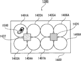
Figure 13 is the schematic diagram of the charging system 1300 in this exemplary embodiments.In Figure 13, be similar to above-mentioned exemplary embodiments, charging device 1400 uses electromagnetic induction to charge in the noncontact mode.Charging device 1400 is tabular, and is equipped with 8 charhing unit 1401A~1408A that include charge coil.
Charging destination apparatus 1500 is placed on any charhing unit of charging device 1400, so that can be the battery charge of charging destination apparatus 1500.Charging destination apparatus 1500 is structurally identical with the charging destination apparatus 300 shown in Fig. 2 B, and receives electric power with to battery charge in the noncontact mode.This exemplary embodiments uses wireless near field communication to communicate by letter with charging device 1400 with the different communication units 305 that are of the exemplary embodiments of Fig. 2 B.
Figure 14 is the block diagram that the structure of charging device 1400 is shown.
Be used to discern the processing of charging destination apparatus in this exemplary embodiments of flowchart text below with reference to Figure 15.
At step S1501, object is placed on the charging device 1400, this changes the output of some coils, and detecting unit 1420 is to the variation of control unit 1411 notice coil (charhing unit) outputs.At step S1502, control unit 1411 judges whether only to have placed object on a charhing unit.If placing object on some charhing units and on other charhing unit, do not placing other object (step S1502 is a "Yes"), then at step S1509, control unit 1411 selects detected charhing unit to be included in communication unit in its communication range from two communication units 1422 and 1426.At step S1510, selected communication unit is communicated by letter with object.If the object of being placed is a charging destination apparatus 1500, then communication unit inquiry charging destination apparatus 1500 it be the equipment of which kind, and obtain the information relevant with the destination apparatus 1500 of charging.At step S1510, control unit 1411 is based on the information Recognition charging destination apparatus from communication unit obtained.
In addition, in this exemplary embodiments, as the information of charging destination apparatus, information such as the charging capacity of acquisition battery and maximum charging voltage.Control unit 1411 control with its on placed the corresponding coil stimulating of the charhing unit unit of charging destination apparatus 1500, with transmission be suitable for the charging electric power of destination apparatus.
Placed object (step S1502 is a "No") if control unit 1411 is judged on a plurality of charhing units, then at step S1503, control unit 1411 judges that whether detected charhing unit is the charhing unit in the communication range of same communication unit.If the charhing unit of having placed object on it is in the communication range of different mutually communication units 1422 and 1426 (step S1503 is a "No"), then at step S1511, communication unit 1422 and 1426 is similar to communicating by letter of step S1510, with identification charging destination apparatus 1500.
If control unit 1411 is judged detected a plurality of charhing unit (step S1503 is a "Yes") in the communication range of same communication unit, then at step S1504, control unit 1411 selects detected charhing unit to be included in communication unit in its communication range from two communication units.At step S1505, control unit 1411 judges whether to have identified the charging destination apparatus on the charhing unit of being placed in except that new detected charhing unit.
For example, if the destination apparatus that will charge earlier places on another charhing unit that then another object is placed the same communication scope on the charhing unit, then identified the charging destination apparatus (step S1505 is a "Yes") of first placement.In this case, handle and enter step S1510, and communicate at the selected communication unit of step S1504.At this moment, if placed two charging destination apparatus 1500, then communication unit receives replying from two charging destination apparatus.Owing to identified a charging destination apparatus, then another device can be identified as the device of new placement.Therefore, can discern the device that is placed on these two charhing units.
If fail to identify any device (step S1505 is a "No"), then at step S1506, an excitation and a corresponding coil of charhing unit in the detected a plurality of charhing units of step S1501, and stop to encourage other coil.At step S1507, whether the coil 301 that selected communication unit communicates with inquiry charging destination apparatus is receiving electric power.At this moment, communication unit may receive from a plurality of charging destination apparatus and reply.Yet its device of replying that is receiving electric power of known transmission is that the coil that is encouraged transmits the device of electric power to it.Thereby, its device that is receiving electric power of transmission can be identified as the device on the corresponding charhing unit of the coil that is placed in and is encouraged.
At step S1508, control unit 1411 is judged the processing of whether all having passed through step S1506 and S1507 at detected all charhing units of step S1501.Thereby, each charhing unit is carried out similar processing is placed in charging destination apparatus 1500 on it with identification.
Control unit 1411 identification is placed in the charging destination apparatus on each charhing unit, and according to by the information Control coil stimulating unit 1412~1419 that communication unit obtained, and is suitable for electric power to the charging of charging destination apparatus with transmission.
Figure 16 is the schematic diagram that illustrates according to the structure of the charging system 1600 of the 5th exemplary embodiments.Charging system 1600 comprises charging device 1700 and charging destination apparatus 300.In addition, in this exemplary embodiments, the situation of charging device 200 is the same as described above, and charging device 1700 uses electromagnetic induction to charge in the noncontact mode.Charging device 1700 comprises and is used for the coil that charges in the noncontact mode.Charging destination apparatus 300 is placed four charhing unit 1701A~1704A that are used for by the coil supply electric power that comprises, thus can be to being included in the battery charge in the charging destination apparatus 300.
As charging destination apparatus 300, Figure 16 illustrates portable phone 300A, digital camera 300B and video camera 300C.Yet the present invention is applicable to other device that can communicate by letter with charging device 1700.
As the situation of charging device 200, charging device 1700 is by the processing described in the above-mentioned exemplary embodiments, and identification is placed in the charging destination apparatus 300 on charhing unit 1701A~1704A.Charging device 1700 also comprises display unit 1717.Display unit 1717 shows that expression is placed in the icon and the button of expression to the performed function of charging destination apparatus of the charging destination apparatus on charhing unit 1701A~1704A.Display unit 1717 is that user's touch sensitive display unit 1717 is to import the touch panel of various instructions.
Figure 17 is the block diagram that the structure of charging device 1700 is shown.
For example, charging device 1700 is similar to the processing of first exemplary embodiments, is placed in charging destination apparatus on charhing unit 1701A~1704A with identification, thus the control charging process.
The various buttons that indicative control unit 1718 display operation on liquid crystal panel 1719 is used.The image that icon and button are used is stored in the memory 1721.Touch sensor 1720 detects users and touches display frame, is sent to indicative control unit 1718 with the information that the position that is touched with the user is relevant.Indicative control unit 1718 detects user's operation based on the output of touch sensor 1720, and sends it to control unit 1707.Control unit 1707 is carried out the described processing in back according to user's operation.
Figure 18 illustrates the display frame of display unit 1717.In this exemplary embodiments, the power supply of opening charging device 1700 is to show picture shown in Figure 180 automatically on display unit 1717.As shown in figure 16, for example, if as the charging destination apparatus, portable phone 300A, digital camera 300B and video camera 300C are placed respectively on charhing unit 1701A, the 1702A and 1704A of charging device 1700, then show the icon of these devices as shown in figure 18.In Figure 18, in the display frame of charging device 1700,, show the icon of these devices with the regional corresponding position of charhing unit.If on charging device 1700, place the charging destination apparatus, display icon not then.The Control on Communication picture that replaces the automatic Figure 18 of demonstration shows picture shown in Figure 180 during operation direction display unit 1717 these pictures of demonstration that can work as the user.
In Figure 18, display frame 1801 shows that expression is placed in the icon 1802~1804 of the device on the charging device 1700.Button 1805, indication that the video data function uses begin to charge button 1806, the indication of usefulness stop the to charge button 1807 and the cancel button 1808 of usefulness are gone back in display frame 1801.
In this exemplary embodiments, although with the storage of icon 1802~1804 in memory 1721, can also obtain the data of icon from each device.As long as can discern each device, then replace icon, can show other image.
The user touches display frame 1801 and indicates operation.
Use below and operate relevant processing with the user in this exemplary embodiments of flowchart text of Figure 19.Carry out the processing of Figure 19 by control unit 1707 each unit of control.As mentioned above, when identification is placed in device on charhing unit 1701A~1704A, as shown in figure 18, on display unit 1717, show display frame 1801.Obtain the employed information of transfer of data from each device.
In this state, the user touches the icon of the device that will operate, touches each function button then to indicate the operation to the device that is touched.At step S1901, if control unit 1707 is judged the icon that has touched arbitrary device, then control unit 1707 judges whether to have touched transfer of data button 1805 at step S1902 subsequently.If touched transfer of data button 1805 (step S1902 is a "Yes"),, on display unit 1717, show to be used to ask the user to touch the information of the device that sends the destination then at step S1903.In this case, show the device that is stored in the transmission source touch the device that sends the destination the request user before, i.e. the table of the data in the device that step S1901 is touched, and user can be selected the data that will send from these data.
At step S1904, if touched the icon of the device that sends the destination, then at step S1905, communication unit 1713 is from sending the device for reading data in source, and these data are sent to the device that sends the destination.
At step S1906, if touched charging start button 1806, then at step S1907, the charhing unit of having placed the device that is touched begins charging.At step S1908, if touched charging stop button 1807, then at step S1909, the charhing unit of having placed the device that is touched stops charging.In this exemplary embodiments, by operation cancel button 1808, display frame is back to display frame 1801.At this moment, can stop or continuing carrying out data transmission and processing and the charging process of just carrying out.
Therefore, this exemplary embodiments is not only discerned the device that is placed on each charhing unit, but also shows the icon and the functional buttons being operated of the device of being placed.Then, the user operates to transmit data between device.
Be similar to above-mentioned exemplary embodiments, if, then can not show charging start button 1806 as long as the identification of a finishing device just begins the device that charges or selected just charging.The destination apparatus of can asking to charge sends the information relevant with the current residual battery capacity, to show the battery capacity of charging destination apparatus.
In above-mentioned exemplary embodiments, charging device is tabular, and the destination apparatus that will charge places on the charging device so that can carry out non-contact charge.
Except that said structure, can adopt other structure, in this structure, can the arranged perpendicular charging device, perhaps can each device be configured near the charhing unit, thereby charge in the noncontact mode by hanging each device.In addition, in this case, if having the charging destination apparatus of a plurality of charhing units, then each device of identification, and control charging process to its supply electric power.
Although the present invention has been described, should be appreciated that the present invention is not limited to disclosed exemplary embodiments with reference to exemplary embodiments.The scope of appended claims meets the wideest explanation, to comprise all these class modifications, equivalent structure and function.
Claims (20)
1. equipment that is used for to a plurality of external device (ED)s supply electric power with battery comprises:
A plurality of electric power supply units are used in the noncontact mode to described a plurality of external device (ED) supply electric power;
Acquiring unit is used to obtain the information relevant with the electric power accepting state, and whether each external device (ED) in the described a plurality of external device (ED)s of described information representation is receiving electric power; And
Recognition unit is used for based on the described information of being obtained, and discerns the external device (ED) that each electric power supply unit in described a plurality of electric power supply unit supplies power to.
2. equipment according to claim 1 is characterized in that, also comprises detecting unit, and described detecting unit is used for detecting the electric power supply unit of described a plurality of electric power supply unit to described external device (ED) supply electric power,
Wherein, described recognition unit is discerned the external device (ED) that is supplied power to by the detected electric power supply unit of described detecting unit.
3. equipment according to claim 1 is characterized in that, also comprises control unit, and described control unit is used to control described a plurality of electric power supply unit and whether supplies electric power,
Wherein, the described information of described recognition unit when making electric power supply unit supply electric power in described a plurality of electric power supply unit when described control unit and making electric power supply unit stop supplies electric power except that a described electric power supply unit is discerned a described external device (ED) that electric power supply unit supplies power to.
4. equipment according to claim 1 is characterized in that, also comprises control unit, and described control unit is used to control described a plurality of electric power supply unit and whether supplies electric power,
Wherein, described information and the described information when described control unit make described a plurality of electric power supply unit stop supplies electric power of described recognition unit when making described a plurality of electric power supply unit supply electric power when described control unit is discerned the external device (ED) that described a plurality of electric power supply unit supplies power to.
5. equipment according to claim 4 is characterized in that,
Described control unit switches between the state of the state of described a plurality of electric power supply units supply electric power and described a plurality of electric power supply unit stop supplies electric power with preassigned pattern, described acquiring unit obtains the information relevant with the electric power accepting state of other external device (ED), and the handover operation that described recognition unit carries out with described preassigned pattern according to described control unit, based on the information of obtaining by described acquiring unit, discern the external device (ED) that described a plurality of electric power supply unit supplies power to.
6. equipment according to claim 1 is characterized in that, also comprises communication unit, and described communication unit is used for communicating by letter with described external device (ED),
Wherein, described acquiring unit from the information that described external device (ED) receives, obtains the described information relevant with the electric power accepting state based on described communication unit.
7. equipment according to claim 1 is characterized in that, also comprises a plurality of communication units, and described a plurality of communication units are used for communicating by letter with described external device (ED),
Wherein, described acquiring unit from the information that described external device (ED) receives, obtains the described information relevant with the electric power accepting state based on described a plurality of communication units.
8. equipment according to claim 1 is characterized in that,
Described acquiring unit obtains the information relevant with charging process of the external device (ED) that is identified by described recognition unit, and described acquiring unit comprises control unit, described control unit is used for controlling the operation of described a plurality of electric power supply units based on the information of being obtained relevant with charging process.
9. equipment according to claim 1 is characterized in that,
Described external device (ED) comprises the device and the control unit that can communicate, and described control unit is used for making transmits data between two external device (ED)s selecting from a plurality of external device (ED)s that identified by described recognition unit.
10. equipment according to claim 9, it is characterized in that, also comprise selected cell, described selected cell is used for a plurality of external device (ED)s of identifying from by described recognition unit, selects to send the device in source and send the device of destination as data as data.
11. equipment according to claim 1 is characterized in that, also comprises display unit, the information of the external device (ED) that described display unit is used to show that expression identifies.
12. an equipment that is used for to the external device (ED) supply electric power with battery comprises:
A plurality of electric power supply units are used in the noncontact mode to described external device (ED) supply electric power, wherein, described external device (ED) be configured in the corresponding a plurality of presumptive areas of described a plurality of electric power supply units in;
Recognition unit is used to discern described external device (ED);
Display unit is used to show and the relevant information of a plurality of external device (ED)s that identifies; And
Control unit is used to control a plurality of external device (ED)s that identify, to transmit data between a plurality of external device (ED)s that identify.
13. a method that is used for to a plurality of external device (ED) supply electric power with battery comprises:
Supply electric power in the noncontact mode to described a plurality of external device (ED)s by a plurality of electric power supply units;
Obtain the information relevant with the electric power accepting state by acquiring unit, whether each external device (ED) in the described a plurality of external device (ED)s of described information representation is receiving electric power; And
The external device (ED) that supplies power to based on each electric power supply unit in the described a plurality of electric power supply units of the described information Recognition of being obtained by recognition unit.
14. method according to claim 13 is characterized in that, also comprises by detecting unit detecting the electric power supply unit of supplying electric power in described a plurality of electric power supply unit to described external device (ED),
Wherein, described recognition unit is discerned the external device (ED) that is supplied power to by the detected electric power supply unit of described detecting unit.
15. method according to claim 13 is characterized in that, comprises also whether control described a plurality of electric power supply unit by control unit supplies electric power,
Wherein, the described information of described recognition unit when making electric power supply unit supply electric power in described a plurality of electric power supply unit when described control unit and making electric power supply unit stop supplies electric power except that a described electric power supply unit is discerned a described external device (ED) that electric power supply unit supplies power to.
16. method according to claim 13 is characterized in that, comprises also whether control described a plurality of electric power supply unit by control unit supplies electric power,
Wherein, described information and the described information when described control unit make described a plurality of electric power supply unit stop supplies electric power of described recognition unit when making described a plurality of electric power supply unit supply electric power when described control unit is discerned the external device (ED) that described a plurality of electric power supply unit supplies power to.
17. method according to claim 16 is characterized in that, also comprises:
Between the state of the state of described a plurality of electric power supply units supply electric power and described a plurality of electric power supply unit stop supplies electric power, switch with preassigned pattern by described control unit; And
Obtain the information relevant by described acquiring unit with the electric power accepting state of other external device (ED),
Wherein, the handover operation that described recognition unit carries out with described preassigned pattern according to described control unit based on the information of being obtained by described acquiring unit, is discerned the external device (ED) that described a plurality of electric power supply unit supplies power to.
18. method according to claim 13 is characterized in that, also comprises by communication unit communicating by letter with described external device (ED),
Wherein, based on by described communication unit from the information that described external device (ED) receives, obtain the described information relevant with the electric power accepting state.
19. method according to claim 13 is characterized in that, also comprises by a plurality of communication units communicating by letter with described external device (ED),
Wherein, based on by described a plurality of communication units from the information that described external device (ED) receives, obtain the described information relevant with the electric power accepting state.
20. method according to claim 13 is characterized in that, also comprises:
Obtain the information relevant of the external device (ED) that identifies by described recognition unit with charging process by described acquiring unit; And
By the operation of control unit based on the described a plurality of electric power supply units of being obtained of information Control relevant with charging process.
Applications Claiming Priority (2)
| Application Number | Priority Date | Filing Date | Title |
|---|---|---|---|
| JP2009-018278 | 2009-01-29 | ||
| JP2009018278A JP5566035B2 (en) | 2009-01-29 | 2009-01-29 | Charging apparatus and method |
Publications (1)
| Publication Number | Publication Date |
|---|---|
| CN101795022A true CN101795022A (en) | 2010-08-04 |
Family
ID=42353644
Family Applications (1)
| Application Number | Title | Priority Date | Filing Date |
|---|---|---|---|
| CN201010106079A Pending CN101795022A (en) | 2009-01-29 | 2010-01-29 | Equipment and method to external device (ED) supply electric power |
Country Status (3)
| Country | Link |
|---|---|
| US (1) | US20100188041A1 (en) |
| JP (1) | JP5566035B2 (en) |
| CN (1) | CN101795022A (en) |
Cited By (10)
| Publication number | Priority date | Publication date | Assignee | Title |
|---|---|---|---|---|
| CN102637915A (en) * | 2011-02-15 | 2012-08-15 | 索尼公司 | Battery, battery pack, battery charger, and battery charging system |
| CN102638110A (en) * | 2011-02-10 | 2012-08-15 | 佳能株式会社 | Power supply apparatus and control method |
| CN103229383A (en) * | 2010-11-16 | 2013-07-31 | 鲍尔拜普罗克西有限公司 | A wirelessly rechargeable battery and power transmitter |
| CN104428758A (en) * | 2012-07-10 | 2015-03-18 | 富士胶片株式会社 | Information distribution method, information distribution program, information distribution server, and charging device |
| CN104795904A (en) * | 2010-09-30 | 2015-07-22 | 英特尔公司 | Wireless power transfer apparatus and method thereof |
| US9178360B2 (en) | 2011-02-22 | 2015-11-03 | Canon Kabushiki Kaisha | Power supply apparatus, method, and storage medium to output wireless power, detect value relating to output power, and charge based on detected value |
| CN105337330A (en) * | 2014-08-11 | 2016-02-17 | 联想(北京)有限公司 | Control method and electronic apparatus |
| CN105474500A (en) * | 2013-06-28 | 2016-04-06 | 诺基亚技术有限公司 | Method and apparatus for determination of a non-charging operation |
| CN108450044A (en) * | 2015-11-10 | 2018-08-24 | Lg伊诺特有限公司 | Multi-coil wireless charging method and its device and system |
| CN110797987A (en) * | 2018-08-02 | 2020-02-14 | Oppo广东移动通信有限公司 | Charging position prompting method and device, storage medium and charging equipment |
Families Citing this family (39)
| Publication number | Priority date | Publication date | Assignee | Title |
|---|---|---|---|---|
| EP2375534A1 (en) * | 2010-04-09 | 2011-10-12 | Nxp B.V. | Apparatus for transferring energy to an accumulator and system for charging an electric accumulator |
| JP5548514B2 (en) * | 2010-04-27 | 2014-07-16 | キヤノン株式会社 | Charging system |
| JP5789790B2 (en) * | 2010-09-10 | 2015-10-07 | パナソニックIpマネジメント株式会社 | Power transmission device and wireless power transmission system |
| EP2624413B1 (en) * | 2010-10-01 | 2021-01-27 | Panasonic Intellectual Property Management Co., Ltd. | Electricity supply system for electric automobile, and electric automobile and power supply device used in said system |
| JP5869759B2 (en) * | 2010-11-04 | 2016-02-24 | キヤノン株式会社 | Wireless power transmission system, wireless power transmission system control method, wireless power transmission device, wireless power transmission device control method, and program |
| KR101768723B1 (en) * | 2011-03-30 | 2017-08-17 | 삼성전자주식회사 | Method and system for wireless charging in a portable terminal |
| KR101785456B1 (en) * | 2011-04-25 | 2017-11-06 | 엘지전자 주식회사 | Apparatus and system for providing wireless power charge service |
| JP5777954B2 (en) * | 2011-07-01 | 2015-09-16 | シャープ株式会社 | Charging stand control terminal, charging stand controlled by the charging stand control terminal, control method of charging stand control terminal, charging stand control method, charging stand control terminal control program, charging stand control program, and recording medium |
| KR101781650B1 (en) | 2011-10-04 | 2017-09-26 | 삼성전자주식회사 | Wireless power multi-charge method and power transmitter |
| JP5895449B2 (en) | 2011-10-28 | 2016-03-30 | 日立化成株式会社 | Non-contact power transmission device and non-contact power transmission system |
| WO2013080393A1 (en) * | 2011-11-28 | 2013-06-06 | パナソニック株式会社 | Charging device, charged device |
| TW201347344A (en) * | 2012-01-08 | 2013-11-16 | Access Business Group Int Llc | Wireless power transfer through conductive materials |
| KR20130096020A (en) * | 2012-02-21 | 2013-08-29 | 삼성전자주식회사 | Method for wireless charging and apparatus for the same |
| KR20130098546A (en) * | 2012-02-28 | 2013-09-05 | 삼성전자주식회사 | Method and devices for transmitting signal from a plurality of wireless power receivers to wireless power provider |
| JP6083121B2 (en) * | 2012-03-22 | 2017-02-22 | 株式会社豊田自動織機 | Power feeding device and charging device, power feeding method and power feeding program |
| MX363242B (en) | 2012-03-28 | 2019-03-14 | Fujitsu Ltd | Wireless power transmission system and wireless power transmission method. |
| JP2014023253A (en) * | 2012-07-17 | 2014-02-03 | Nikon Corp | Device placement unit and control program for device placement unit |
| US9385557B2 (en) | 2012-08-23 | 2016-07-05 | At&T Mobility Ii Llc | Methods, systems, and products for charging of devices |
| CN102813558B (en) * | 2012-08-30 | 2015-03-25 | 上海携福电器有限公司 | Electric toothbrush |
| KR101462730B1 (en) * | 2012-11-15 | 2014-11-17 | 삼성전기주식회사 | Charging apparatus and wireless charging apparatus |
| US9118188B2 (en) * | 2012-12-17 | 2015-08-25 | Intel Corporation | Wireless charging system |
| JP6120576B2 (en) * | 2013-01-11 | 2017-04-26 | キヤノン株式会社 | Power supply apparatus and power supply method |
| KR102149528B1 (en) * | 2013-10-22 | 2020-10-26 | 한국전자통신연구원 | Multi-function wireless charging device |
| KR102147550B1 (en) * | 2014-02-17 | 2020-08-24 | 엘에스전선 주식회사 | Wireless power transmission apparatus, wireless power reception apparatus, wireless power transmission apparatus system, and wireless power transmission method |
| US9094495B1 (en) * | 2014-04-21 | 2015-07-28 | Symbol Technologies, Llc | System and method for energy management within a group of devices |
| EP3149501B1 (en) | 2014-05-30 | 2018-11-14 | Apple Inc. | Battery usage tracking user interface |
| DE212015000194U1 (en) | 2014-08-06 | 2017-05-31 | Apple Inc. | Reduced user interfaces for battery management |
| JP6894594B2 (en) | 2015-03-31 | 2021-06-30 | 株式会社NejiLaw | Parts, information acquisition system |
| CN104953881B (en) * | 2015-07-17 | 2018-12-25 | 南京矽力杰半导体技术有限公司 | Driving circuit and the radio energy transmitting terminal for applying it |
| CN105099002B (en) * | 2015-07-17 | 2018-09-04 | 南京矽力杰半导体技术有限公司 | Driving circuit and apply its radio energy transmitting terminal |
| JP5998267B2 (en) * | 2015-11-09 | 2016-09-28 | パイオニア株式会社 | Charging control apparatus and method, charging system, association method, and computer program |
| KR102525312B1 (en) * | 2015-11-10 | 2023-04-25 | 삼성전자주식회사 | Electronic device and method for controlling wireless charging |
| KR102543298B1 (en) * | 2015-11-17 | 2023-06-14 | 삼성전자주식회사 | Method and device to transfer power wirelessly |
| US10601256B2 (en) * | 2016-02-17 | 2020-03-24 | Integrated Device Technology, Inc. | Wireless power transfers with frequency range scanning |
| KR101635084B1 (en) * | 2016-03-31 | 2016-06-30 | 주식회사 핀크래프트엔지니어링 | Multi charging device enabled by current and voltage control |
| AU2018279782C1 (en) * | 2017-06-04 | 2021-02-25 | Apple Inc. | Multi-device charging user interface |
| US10951043B2 (en) * | 2017-06-04 | 2021-03-16 | Apple Inc. | Multi-device charging user interface |
| US10270270B2 (en) * | 2017-06-04 | 2019-04-23 | Apple Inc. | Coordinating complementary notifications across related computing devices connected to a wireless charging apparatus |
| US11646591B2 (en) | 2019-05-09 | 2023-05-09 | Apple Inc. | Indication for protective charging mode |
Citations (3)
| Publication number | Priority date | Publication date | Assignee | Title |
|---|---|---|---|---|
| US20070139000A1 (en) * | 2005-03-03 | 2007-06-21 | Yosuke Kozuma | System, apparatus and method for supplying electric power, apparatus and method for receiving electric power, storage medium and program |
| US20080258679A1 (en) * | 2007-03-01 | 2008-10-23 | Manico Joseph A | Charging display system |
| US20090315510A1 (en) * | 2006-08-03 | 2009-12-24 | Cesario Dos Santos | Battery Monitoring and Maintenance for Medical Device |
Family Cites Families (9)
| Publication number | Priority date | Publication date | Assignee | Title |
|---|---|---|---|---|
| US6967462B1 (en) * | 2003-06-05 | 2005-11-22 | Nasa Glenn Research Center | Charging of devices by microwave power beaming |
| JP2005143181A (en) * | 2003-11-05 | 2005-06-02 | Seiko Epson Corp | Noncontact power transmitter |
| US7952322B2 (en) * | 2006-01-31 | 2011-05-31 | Mojo Mobility, Inc. | Inductive power source and charging system |
| KR100792308B1 (en) * | 2006-01-31 | 2008-01-07 | 엘에스전선 주식회사 | A contact-less power supply, contact-less charger systems and method for charging rechargeable battery cell |
| JP5124991B2 (en) * | 2006-05-30 | 2013-01-23 | ソニー株式会社 | COMMUNICATION SYSTEM, COMMUNICATION DEVICE, COMMUNICATION METHOD, AND PROGRAM |
| US7948208B2 (en) * | 2006-06-01 | 2011-05-24 | Mojo Mobility, Inc. | Power source, charging system, and inductive receiver for mobile devices |
| JP2008017592A (en) * | 2006-07-05 | 2008-01-24 | Ricoh Elemex Corp | Information display system device |
| JP4600462B2 (en) * | 2007-11-16 | 2010-12-15 | セイコーエプソン株式会社 | Power transmission control device, power transmission device, electronic device, and non-contact power transmission system |
| JP4893689B2 (en) * | 2008-05-09 | 2012-03-07 | セイコーエプソン株式会社 | Power receiving device, electronic device, non-contact power transmission system, and power transmitting device |
-
2009
- 2009-01-29 JP JP2009018278A patent/JP5566035B2/en active Active
-
2010
- 2010-01-26 US US12/694,057 patent/US20100188041A1/en not_active Abandoned
- 2010-01-29 CN CN201010106079A patent/CN101795022A/en active Pending
Patent Citations (3)
| Publication number | Priority date | Publication date | Assignee | Title |
|---|---|---|---|---|
| US20070139000A1 (en) * | 2005-03-03 | 2007-06-21 | Yosuke Kozuma | System, apparatus and method for supplying electric power, apparatus and method for receiving electric power, storage medium and program |
| US20090315510A1 (en) * | 2006-08-03 | 2009-12-24 | Cesario Dos Santos | Battery Monitoring and Maintenance for Medical Device |
| US20080258679A1 (en) * | 2007-03-01 | 2008-10-23 | Manico Joseph A | Charging display system |
Cited By (17)
| Publication number | Priority date | Publication date | Assignee | Title |
|---|---|---|---|---|
| CN104795904A (en) * | 2010-09-30 | 2015-07-22 | 英特尔公司 | Wireless power transfer apparatus and method thereof |
| US9318780B2 (en) | 2010-11-16 | 2016-04-19 | Powerbyproxi Limited | Wirelessly rechargeable battery and power transmitter |
| CN103229383A (en) * | 2010-11-16 | 2013-07-31 | 鲍尔拜普罗克西有限公司 | A wirelessly rechargeable battery and power transmitter |
| US9379570B2 (en) | 2011-02-10 | 2016-06-28 | Canon Kabushiki Kaisha | Power supply apparatus, method, and storage medium to output wireless power and charge based on value relating to output power and efficiency |
| CN102638110A (en) * | 2011-02-10 | 2012-08-15 | 佳能株式会社 | Power supply apparatus and control method |
| CN102638110B (en) * | 2011-02-10 | 2015-04-22 | 佳能株式会社 | Power supply apparatus and control method |
| CN102637915B (en) * | 2011-02-15 | 2016-01-20 | 索尼公司 | Battery, battery pack, battery charger and batter-charghing system |
| CN102637915A (en) * | 2011-02-15 | 2012-08-15 | 索尼公司 | Battery, battery pack, battery charger, and battery charging system |
| US9178360B2 (en) | 2011-02-22 | 2015-11-03 | Canon Kabushiki Kaisha | Power supply apparatus, method, and storage medium to output wireless power, detect value relating to output power, and charge based on detected value |
| CN104428758A (en) * | 2012-07-10 | 2015-03-18 | 富士胶片株式会社 | Information distribution method, information distribution program, information distribution server, and charging device |
| CN104428758B (en) * | 2012-07-10 | 2016-04-06 | 富士胶片株式会社 | Information issuing method, Information issued program, information delivery server, charging device |
| CN105474500A (en) * | 2013-06-28 | 2016-04-06 | 诺基亚技术有限公司 | Method and apparatus for determination of a non-charging operation |
| CN105337330A (en) * | 2014-08-11 | 2016-02-17 | 联想(北京)有限公司 | Control method and electronic apparatus |
| CN105337330B (en) * | 2014-08-11 | 2018-08-31 | 联想(北京)有限公司 | A kind of control method and electronic device |
| CN108450044A (en) * | 2015-11-10 | 2018-08-24 | Lg伊诺特有限公司 | Multi-coil wireless charging method and its device and system |
| CN110797987A (en) * | 2018-08-02 | 2020-02-14 | Oppo广东移动通信有限公司 | Charging position prompting method and device, storage medium and charging equipment |
| CN110797987B (en) * | 2018-08-02 | 2021-08-24 | Oppo广东移动通信有限公司 | Charging position prompting method and device, storage medium and charging equipment |
Also Published As
| Publication number | Publication date |
|---|---|
| JP2010178498A (en) | 2010-08-12 |
| JP5566035B2 (en) | 2014-08-06 |
| US20100188041A1 (en) | 2010-07-29 |
Similar Documents
| Publication | Publication Date | Title |
|---|---|---|
| CN101795022A (en) | Equipment and method to external device (ED) supply electric power | |
| EP2579421B1 (en) | Wireless power transmitting apparatus and method thereof | |
| US10622827B2 (en) | Non-contact electric power transmission system, charging station, and vehicle | |
| JP7026646B2 (en) | A wireless power transmission control method in a resonance type wireless power transmission system, a wireless power transmission device using the same, and a wireless power receiving device using the same. | |
| US8541975B2 (en) | System and method for efficient wireless charging of a mobile terminal | |
| JP5111397B2 (en) | Non-contact charging device provided with coil array, non-contact charging system and charging method | |
| US20190058361A1 (en) | Wireless power transfer system, control method of wireless power transfer system, wireless power transmitting apparatus, control method of wireless power transmitting apparatus, and storage medium | |
| CN104995815B (en) | Wireless power transmitter and receiver, and pass through the method for wireless power transmitter unlicensed radio power receiver | |
| JP5610703B2 (en) | Charger and control method | |
| CN102315695B (en) | Power supply apparatus, power supply system, and control method | |
| US20110260681A1 (en) | Portable Wireless Charging Device | |
| KR100734676B1 (en) | Apparatus for wireless charging having multi-charge cell and Method for controlling the same | |
| JP2010130729A (en) | Charging equipment, transmission equipment, and noncontact charging system | |
| WO2008056415A1 (en) | Non-contact charger, electronic device, battery pack, and non-contact charge system | |
| CN104037952A (en) | Wireless charger and charging system with multi-compatibility | |
| CN107437850A (en) | By the transmitter of wireless charging system and the method and its performs device of receiver pairing | |
| JP6186372B2 (en) | Wireless power transmission apparatus and method | |
| JP2013179723A (en) | Charge device and charge method | |
| JP2018143031A (en) | Power supply device, electronic apparatus, control method therefor, program, and wireless power transmission system | |
| JP2015136219A (en) | Charged apparatus, control method thereof, and control program, and non-contact charging system | |
| JP2021093828A (en) | Power receiving device, power transmission device, and control method thereof, and program | |
| KR20180036010A (en) | A wireless power transmitter and thereof operation method | |
| KR101610678B1 (en) | Wireless charging apparatus with information providing function | |
| JP2015082964A (en) | Non-contact power transmission system and power reception device | |
| JP2019537411A (en) | Energy transmission device and energy transmission method |
Legal Events
| Date | Code | Title | Description |
|---|---|---|---|
| C06 | Publication | ||
| PB01 | Publication | ||
| C10 | Entry into substantive examination | ||
| SE01 | Entry into force of request for substantive examination | ||
| C02 | Deemed withdrawal of patent application after publication (patent law 2001) | ||
| WD01 | Invention patent application deemed withdrawn after publication |
Application publication date: 20100804 |