CN101778607A - The implantable device and the method that are used for external beam radiation treatments - Google Patents
The implantable device and the method that are used for external beam radiation treatments Download PDFInfo
- Publication number
- CN101778607A CN101778607A CN200880100979A CN200880100979A CN101778607A CN 101778607 A CN101778607 A CN 101778607A CN 200880100979 A CN200880100979 A CN 200880100979A CN 200880100979 A CN200880100979 A CN 200880100979A CN 101778607 A CN101778607 A CN 101778607A
- Authority
- CN
- China
- Prior art keywords
- coil
- marker
- patient
- flexible
- active marker
- Prior art date
- Legal status (The legal status is an assumption and is not a legal conclusion. Google has not performed a legal analysis and makes no representation as to the accuracy of the status listed.)
- Pending
Links
Images


Classifications
-
- A—HUMAN NECESSITIES
- A61—MEDICAL OR VETERINARY SCIENCE; HYGIENE
- A61N—ELECTROTHERAPY; MAGNETOTHERAPY; RADIATION THERAPY; ULTRASOUND THERAPY
- A61N5/00—Radiation therapy
- A61N5/10—X-ray therapy; Gamma-ray therapy; Particle-irradiation therapy
- A61N5/1048—Monitoring, verifying, controlling systems and methods
- A61N5/1049—Monitoring, verifying, controlling systems and methods for verifying the position of the patient with respect to the radiation beam
- A61N2005/1051—Monitoring, verifying, controlling systems and methods for verifying the position of the patient with respect to the radiation beam using an active marker
Abstract
The invention discloses a kind of implantable device and method that is used for external beam radiation treatments.The guiding radiation therapy comprises the active marker that is configured to be positioned at described patient and transmits the unionized wireless signal in response to unionized wireless transmission source energy with an embodiment of implantable device.Described device also comprises fastening unit, it is connected with described active marker, and being configured to (a) remains in described marker in the desired distance that described tissue hits and the distortion that (b) suppresses tissue is moved described active marker with respect to described target.
Description
Technical field
The present invention relates to the radiation oncology, and more specifically, relate to the position of the target that accurately is identified for carrying external radiation.
Background
Cancer starts from patient's the cell, and forms the malignant tumor for the treatment of by surgical resection usually.Such surgical operation therapy attempts to remove big as far as possible tumor, but cancerous cell is penetrated in the tissue adjacent with tumor, thereby does not have border clearly.In addition, some programs is attempted treatment edge around restriction tumor with the amount of the health tissues that reduces to remove from the patient.For example, in breast carcinoma, the patient preferably limits the size of lumpectomy to avoid excessively reducing or heterogeneity of breast.These factors have all limited the effect of the surgical procedure that is used for the treatment of cancer.Therefore, radiation therapy becomes the important and height successful method of the localized cancer that is used for the treatment of breast carcinoma, pulmonary carcinoma, the brain cancer and many other types.Radiation therapy is particularly useful for the following: (a) tissue after the tumor resection (b) is positioned at the tumor at middle part, and/or (c) can not carries out the small cell tumor of surgical resection.Radiation therapy can also be as the palliative treatment when healing is impossible.
Recently by following method treatment breast carcinoma: the carcinous breast tissue of surgical resection, and use radiation therapy to center on the residue tissue of excision cavity subsequently.(Xoft Inc.) has developed breast short range radiation therapy equipment and be used for the system of elective irradiation around the part of the tissue of the excision cavity that is produced by lumpectomy for Proxima company (ProximaCorporation) and Xoft company.The therapy equipment of existing breast short range radiation has balloon that is configured to implant in the intramammary cavity and the internal source of radiation that can be placed in the balloon.After carrying out lumpectomy, balloon inserted in the surgical operation cavity and be inflated to balloon be pressed in tissue.Typically balloon was stayed among the patient about 5 days, and carried out twice radiation therapy in the meantime every day.Each radiation therapy comprise insert radiation source in the balloon and excited radiation source to carry ionizing radiation about 10-15 minute.After many days have carried out whole radiation therapies in the therapeutic process, shift out with the balloon venting and from the patient.
Yet breast short range radiation treatment procedure may be challenging.For example, may be difficult to determine whether balloon has accurately been inflated and monitored balloon and kept required size and suitable compliance to guarantee balloon in the excision cavity in the whole many days courses of treatment.The size of balloon is determined by following method at present: beat into radiopaque contrast agent (contrast) in the balloon and the use chi is measured resulting CT or X-ray image.Thereby another type that the patient must carry out CT scan or X-ray to be to obtain image, then the doctor must the evaluation map picture to determine whether balloon be in required size.This is time-consuming and expensive, and it should carry out in the process of the course of treatment every day.The method also makes the patient be exposed to other radiation.
The treatment of breast short range radiation also may have and use the relevant shortcoming of internal source of radiation.For example, balloon may move in the lumpectomy cavity in the course of treatment, and this may cause internal source of radiation to the excessive irradiation in some zones and to other area illumination deficiency.Many existing systems do not detect relative position between balloon and the breast to eliminate this problem.In addition, when radiation source was settled (for example, leaving the rotation center line of balloon) asymmetricly in balloon, the rotation orientation of balloon in the lumpectomy cavity may cause radiation source to be positioned at the position of not expecting with respect to tissue.Routine techniques is not confirmed the rotation orientation of balloon yet.This may be problematic, because after implanting balloon, it can move after the course of treatment, or balloon can be inflated according to plan.Conventional breast short range radiation therapy system is still big relatively, because they must comprise balloon and internal source of radiation simultaneously.Many patients feel under the weather for having radiation source or had the big conduit that stretches out in their bodies in many days in their body, and therefore, a considerable amount of patients select not carry out the treatment of breast short range radiation.In addition, balloon needs bigger member with beyond extending to the patient to the outside, and this may increase the risk of infection.For the other challenge of balloon base therapy comprise to multiple balloon size and dimension need be with the scope that adapts to possible excision cavity and possible dosage inequality.
Consider and the relevant challenge of breast short range radiation treatment procedure, proposed to use the part breast irradiation of external radiation bundle.Although can be with radiant flux, for example three-dimensional conformal radiation therapy (Three-Dimensional Conformal Radiation Therapy) beam shaping centers on the tissue that excises cavity to adapt to target tissue but still be difficult to use external beam radiation to be treated in many application.For example, the size and dimension of cavity may change during the radiocurable typical Duo Ri for external beam, or the treatment target may move during treating.Proposed to use balloon or support to come the some of stabilizing tissue to treat, but balloon also may lock into the challenge of above explanation.Therefore, other program of need improving the external beam radiation that is used for the irradiation of part breast and attempting the controlled treatment edge around the irradiation excision cavity.
The accompanying drawing summary
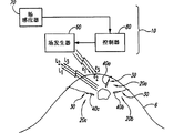
Fig. 1 is the side view that the execution (implementation) of the system that is used to carry out the irradiation of part breast is shown.
Fig. 2 is the sketch map that is used for the implantable device that uses with system with guiding radiation therapy (guided radiation therapy).
Fig. 3 A is the side view of guiding radiation therapy with a specific embodiments of implantable device, and Fig. 3 B is the viewgraph of cross-section of a part of the implantable device of Fig. 3 A.Fig. 3 C and Fig. 3 D are the concrete alternative embodiment of guiding radiation therapy with implantable device.
Fig. 4 is the viewgraph of cross-section that is loaded into an embodiment of the guiding radiation therapy usefulness implantable device in the conductor.
Fig. 5 is the sketch map of operational guidance radiation therapy with an embodiment of system.
Fig. 6 is the diagram that an example of the force curve that is used to shift out implantable device is shown.
Fig. 7 is the schematic side elevation of guiding radiation therapy with another embodiment of implantable device.
Fig. 8 A-8G is the side view of other embodiment of freeing element (decoupling elements) of using in implantable device in the guiding radiation therapy.
Fig. 9 A and 9B are the implantable device that uses in the radiation therapy in the guiding side views with other embodiment of marker.
Figure 10 A and 10E are the side views of other embodiment of the stable element that uses in implantable device in the guiding radiation therapy.
Describe in detail
General introduction
The detail of some embodiments of disclosure is described below with reference to implantable device that is used for external beam radiation treatments and method.Although many in the following embodiment is with reference to being used for the treatment of the part breast irradiation system that excises cavity and program description, described system and implantable device can be used for the treatment of in other program of other symptom.In addition, some other embodiments of the present invention can have therewith those different structures, parts or the program of describing in the part.For example, described equipment and method can have one or more markers or other parts that are used for the external beam radiation therapeutic procedures, the U.S. Patent application 11/165 of described external beam radiation therapeutic procedures as submitting on June 24th, 2005,843 and the U.S. Patent application 11/166 submitted on June 24th, 2005, described in 801, these two U.S. Patent applications all are combined in this by reference.In other example,, there are not detailed demonstration or description and the target location well-known structure relevant with tracking system for fear of the description of unnecessarily covering embodiment of the present invention.Therefore, those of ordinary skills thereby should be appreciated that the present invention can have other embodiment that has other element, or the present invention can have do not have following with reference to Fig. 1-10E show and the feature described in other some embodiments.
The guiding radiation therapy comprises the active marker with circuit with an embodiment of implantable device, and it is configured to implant among the patient and transmits the position signalling of wireless transmission in response to wireless transmission source energy in the patient.In an alternative embodiment, active marker is along lead transmission location signal.Implantable device can also comprise fastening unit, and it has the first that is connected with active marker and is configured at least second portion near patient's corium.Described marker for example can comprise the no lead marker of the circuit with the coil that comprises core and center on core.
The guiding radiation therapy comprises active marker with another embodiment of implantable device, and it is configured to implant in patient's the tissue and in response to unionized wireless transmission source energy and transmits the unionized wireless signal.Implantable device can also comprise the stable element that is connected with marker and shift out line.The target that stable element is configured in the reference tissue remains on implantation position (for example known position) with marker.Shifting out line has the first that is connected with marker and/or stable element and is configured at least second portion near patient's corium.Randomly, implantable device can also comprise frees element, its with shift out line and be connected and separate to near-end from stable element.Freeing the distortion that element for example can be configured to suppress to organize moves active marker with respect to target.
The guiding radiation therapy comprises active marker with another embodiment of implantable device, and it is configured to be positioned at the patient and transmits the unionized wireless signal in response to unionized wireless transmission source energy.This device also comprises fastening unit, and it is connected with active marker and is configured to (a) and remains on marker in the desired distance that tissue hits and the distortion that (b) suppresses tissue is moved active marker with respect to target.
1.
The embodiment of navigation system and implantable device
Fig. 1 is the side view that makes the radiation therapy of target have the navigation system 10 of implantable device 20 easily of being used to according to one embodiment of the invention.In Fig. 1 in the embodiments shown, system 10 has with respect to excision cavity 7 and implants among the patients 6 three independently implantable devices 20 (being labeled as Reference numeral 20a-c respectively).Each implantable device 20 can comprise fastening unit 30 and the marker 40 that is connected with fastening unit 30.In the embodiments shown, implantable device 20a-c comprises marker 40a-c respectively in Fig. 1.Implant 40 can be active marker, and it is configured to response and is positioned at patient's's external (for example beyond corium of patient) energy source and transmits independently position signalling.For example, marker 40 can be the wireless active pick off, and it is the wireless transmission position signalling in response to the excitation signal of wireless transmission.Such wireless active marker can comprise the magnetic transponder of describing as in U.S. Patent application 11/243,478 and 11/166,801, and the full content of these two U.S. Patent applications all is combined in this by reference.Navigation system 10 can also comprise the field power supply 60 to marker 40 wireless transmission excitation signals, measures from the sensor cluster 70 of the position signalling of marker 40 wireless transmission, and controller 80.
In some embodiments, one or more implantable devices 20 are implanted among the patients 6, make marker 40 the most approaching at least excision cavitys 7.Marker 40 thereby relevant with the excision cavity makes marker 40 move based on position, rotation and/or the expansion-contraction of excising cavity 7.In the embodiment shown in Fig. 1, three marker 40a-c are relevant with the excision cavity, but can use singular id device, two markers or more than three markers according to concrete application.For example, two markers may suit, because can accurately locate between target and the marker state and position that in time relative displacement can be used to monitor excision cavity 7.
When marker was in patient 6 or on patient 6, navigation system 10 was determined the physical location of marker 40 in three-dimensional reference frame.In the specific embodiments of system 10 shown in Figure 1, navigation system 10 is in setting up procedure and when the irradiation patient, with respect to absolute external reference is the three-dimensional coordinate of real-time tracking marker 40a-c, to eliminate following influence and guarantee required dosage is applied to target tissue the adjacent tissue of treatment outside, edge.
Some embodiments of implantable device 20 make and can accurately determine the size of excising cavity 7 in patient's the breast under the condition that does not obtain expensive CT image and manual evaluation image.This respect is very useful, because the shape and size of excision cavity 7 may change in the process of treatment.This variation may cause the healthy tissue of external beam radiation irradiation and omit target tissue.By the relative position of positioning marker 40, can be before each treats the period, among and determine the variation of the size and dimension of excision cavity 7 afterwards, to guarantee that the radiation of required dosage is delivered to correct tissue exactly.
Some embodiments of implantable device 20 can also be followed the tracks of excision cavity or other treatment target moving in the process of whole treatment, accurately to carry external beam radiation in the treatment edge.For example breast tissue is soft and easily scratches, and makes the isocenter (isocenter) that may be difficult to the treatment target is remained on the external radiation bundle locate.Because the expansion/contraction of the breast that is caused by breathing, breast also may move in therapeutic process.Some embodiments of implantable device 20 also are used in other displacement of the mobile or breast that detects the patient in the therapeutic process in real time.Therefore, expection implantable device 20 provides accurate measurement to confirm state and the position of treatment target in whole therapeutic process.
Some embodiments of implantable device 20 are also followed the tracks of excision cavity or other target site rotation orientation with respect to health or radiant flux in the whole process of treatment.In some application, the rotation of target site orientation may be important, because excision cavity and other target are not spherical usually, feasible rotation orientation influence treatment edge is with respect to the profile of the position of external beam.Can use navigation system 10 that marker 40 is followed the tracks of or located in addition, to determine the rotation orientation of target with respect to external beam.
Fig. 2 is the sketch map of an embodiment of implantable device 20 of implanting patient 6 corium 8 inside.In this embodiment, fastening unit 30 has line 32, and its first 33 is connected with active marker 40 at distal region, and second portion 34 in proximal region at least near corium 8.Line 32 can be flexible, elongated tether (tether), and it has insulation (dielectric) outside, to prevent induced current and the framing signal of influence in the application of the active marker 40 that uses the transmission alternating magnetic field under the closed circuit situation of online formation.Line 32 for example can be for by insulant (for example polymer), plain conductor and/or have thin slender silk, many filaments, cable and/or their combination of ribbon (ribbon) preparation of insulating coating.In another embodiment again, line 32 can have and is configured to prevent that tissue from merging the outer surface of (for example tissue apposition).In other was used, line 32 can be conductive filament or the lead that does not have insulating coating.Fastening unit 30 can also have the stable element 36 at online 32 first 33 places, and second portion 34 places that free element 38 and online 32 of the line 32 that separates to near-end from stable element 36 shift out parts 39.Free first 33 or second portion 34 places that element 38 can be positioned at line 32.Free element 38 and for example can be positioned at adjacent or first 33 places of approaching line 32 in addition, thereby the second portion 34 of line 32 has the length that is enough to adapt to the purposes that adopts shallow or dark implantation with stable element 36.Such structure makes can be used for the implantable device 20 of single type the different people of different size and/or the different target degree of depth in the patient.According to alternative embodiment, do not comprise and free element.
Fig. 3 A is the side view of a specific embodiments of implantable device 20.In this embodiment, the stable element 36 of fastening unit 30 comprises first coil 51 and frees element 38 and comprises second coil 52.First coil 51 can have and one or morely have first loop diameters and/or spacing (pitch), be configured to comprise larger area winding (for example loop), make the coil 51 of winning marker 40 be remained on the fixed position in first coil, 51 distally.First coil 51 can be made by the first filament portion that comprises polymer, metal or their combination, and filament shows shape memory, superplasticity (superlastic) or their combination, and diameter is 0.025 " to 0.250 ".Among the embodiment that shows in Fig. 3 A, first coil 51 has a loop, because first coil 51 is elongated with coupling in conductor (for example trocar), and will rebound upon deployment, thereby cause marker 40 to move short distance to near-end.Like this, in order to provide good layout accuracy, the displacement of rebounding when some embodiments of first coil 51 have a limited number of winding with the restriction expansion.Second coil 52 can have and one or morely have second loop diameters and/or spacing, be configured to easily with respect to line 32 vertical (for example along the X-direction) expansion/compressions and the winding crooked with respect to line 32 horizontal (for example along Y-and Z-direction).Second coil 52 can comprise the second filament portion of being made by polymer, metal or their combination, and filament shows and comprises that shape memory, superplasticity or their combination, its diameter are 0.025 " to 0.250 ", and diameter is 0.015 " to 0.200 ".Alternatively, the diameter of lead can be the 10-100% of the diameter of marker 40, or lead can be about 30% of the diameter of marker 40.Alternatively, coil can have non-cylindrical geometry (for example, circular cone, hourglass or bucket), thereby changes the mechanical performance of spring.The first and second coil 51-52 can be made by identical materials, the first and second filament portions that make are integral parts of same line, or first and second coil 51-52 can make by different materials, the first and second filament portions that make are the isolating portions that connecting together at the interface.In one embodiment, first coil 51 can have first flexible and second coil 52 and can have second flexiblely, makes stable element 36 flexible ratios free element 38 poor (it is more flexible that for example, stable element 36 is freed element 38 than rigidity).In operation, the first and second coil 51-52 concur, the coil 51 of winning is anchored at marker 40 in the tissue, thereby marker 40 moves with organizing at first coil, 51 far-ends, and second coil 52 is freed the tissue of (decouple) at first coil, 51 near-ends and is moved, and makes the tissue of following move the relative displacement that does not cause between marker 40 and the target.In an alternative embodiment, do not provide and free element; But the tissue of freeing at first coil, 51 near-ends by flexible wire 32 moves, the flexible reduction of its center line 32 or eliminate motion translation to first coil.
Fastening unit 30 can also comprise connector 53, and it is configured to the recess 43 of marker 40 is engaged with the balancing component 54 of freeing element 38 near-ends.Among the embodiment that shows in Fig. 3 A, connector 53 is the coil of the destination county of online 32 first 33, and balancing component 54 is loop or other structure of outer ledger line.The displacement of the marker 40 that causes by rebounding of the first and second coil 51-52 when balancing component 54 reduces to launch, if any, because balancing component 54 provides the other line of freeing element 38 near-ends, its can stable element 36 and free element 38 when rebounding to the far-end tractive.Like this, when launching, stable and free the rebounding of element not to near-end tractive marker 40.Balancing component 54 can further reduce the moving of the near-end second portion 34 of patient's corium place line 32, to reduce the risk that infects.The near-end second portion 34 of line 32 can also have toe-in (knob) 55 or loop 54 so that easier catch with drag wire 32 to extract implantable device 20 out from the patient.Loop 54 also is provided for the coiling at the fixed simple line in corium place.
Fig. 3 B is the side view of the embodiment of marker 40 among Fig. 3 A.In the example that shows in Fig. 3 B, the circuit 44 of marker 40 has core 56, around a plurality of windings 57 of core 56 with seal the overcoat 58 of core 56 and winding 57.In the embodiment that Fig. 3 B shows, shell 41 has cavity, and overcoat 58 is received in the cavity of shell 41.Thereby shell 41 can be the isolating element that connects together with overcoat 58.In other embodiments, thus shell 41 can be configured to seal circuit 44 eliminates isolating overcoat.
Fig. 3 C is the side view of the specific embodiments of implantable device 20.In the embodiment that shows, flexible wire 32 connects front end 42 in the proximal end of the implant 40 that is shown as cone shape.Flexible wire 32 is formed by the combination of different materials or structure or their composite construction, for example, flexible wire can be thin slender silk, many filaments, cable and/or their combination, and it is made by insulant (for example polymer), plain conductor and/or ribbon with insulating coating.Flexible wire 32 is connected with stable element 36 by joint or shaft coupling.According to the each side of this embodiment, nearside front end circular cone 42 is shown as cone shape, comprises 5-15 degree angle.Can in removing the process of marker, make organization grows and allow to remove the power reduction at the cone shape on the near-end of marker.Will be appreciated that as those skilled in the art the angle of circular cone can be greater than 15 degree or less than 5 degree.As will further recognizing, the shape of marker 40 and/or nearside front end circular cone 42 can be circular, square, dihedral, waveform, asymmetric and/or any other geometry.
Fig. 3 D is the viewgraph of cross-section of the alternative embodiment of implantable device 20, and it shows other structure of loop 54 or outer ledger line so that with the coil of wire around be fixed in the corium place.In operation, loop 54 provides user external cable management control.According to the each side of this embodiment, do not need to free element.
Fig. 4 is the viewgraph of cross-section that is loaded into an embodiment of the implantable device 20 in the conductor 90, and described conductor 90 is configured to implantable device 20 is implanted among the patient.In this embodiment, conductor 90 has pipe 91 (for example pins), and it has the rod 93 (for example stylet) in cutting tip 92 (for example sleeve pipe) and the pipe.For example implantable device 20 is loaded in the pipe 91 by first coil 51 that under the condition of stretch around rod 93 second coil 52 or this second coil 52 that do not stretch, stretches.The distally terminal point of rod 93 is placed in the recess 43 of marker 40.In operation, use guidance system such as ultrasonic will manage 91 and the implantable device 20 of loading be inserted among the patient, be placed in the tissue desired locations until marker 40 with respect to target.By regaining pipe 91 and/or promote rod 93 to far-end to near-end implantable device 20 is launched then with respect to pipe 91 with respect to rod 93.Regain when operating as mentioned above when managing 91, first coil 51 springs back to the deployment configuration that it shows in Fig. 3 B.Depend on the method that is used for the coil inlet tube, second coil 52 can or can not rebound.To shift out parts then and connect, and use CT scan or other imaging form to measure the exact position of marker 40 with respect to target at patient's corium place or close patient's corium.Alternatively, rod 93 has and allows filament and extended coil to pass its part or all hollow.
Fig. 5 is the sketch map of operation that the embodiment of the navigation system 10 of the target in the breast that is used for the treatment of the patient and marker 40a-c is shown.Marker 40a-c be used for before the radiation period, among or determine position, orientation, shape, size and/or other parameter of excision cavity or other target afterwards.More specifically, navigation system 10 is determined the position of marker 40a-c and is being provided with, treatment, is launching, provides the target position data in real time to memorizer, user interface, linear accelerator and/or other device in the process of simulation, operation and/or other medical procedures.In an embodiment of navigation system, expression in real time provides the labelling of coordinates of targets as follows to user interface: (a) make the time-out in the data to be differentiated by the people with sufficiently high renewal rate (being frequency), (b), thereby be simultaneously with the measurement of primary signal at least basically with the enough low waiting time.In other embodiments, be defined as in real time and be used to provide the lower frequency range of target data and than the low latency scope, or in other embodiment again, be defined as in real time (for example, with cycle of the position of real-time tracking target aptly or frequency and/or with at least basically with the position data that the obtains marker waiting time simultaneously) target data in response to the position of marker is provided.
Field power supply 60 (for example, pulsed magnetic generator), sensor cluster 70 and controller 80 move together with positioning marker 40.Field power supply 60 produces excitation energy to excite at least one among the marker 40a-c among the patient 6.The embodiment of the field power supply 60 that shows among Fig. 5 produces the pulsed magnetic field of different frequency.For example, field power supply 60 can frequency partition (frequency multiplex) be in the magnetic field of first frequency E1 to excite the first marker 40a, the magnetic field that frequency partition is in second frequency E2 is in the magnetic field of the 3rd frequency E3 to excite the 3rd marker 40c to excite the second marker 40b and frequency partition.In response to excitation energy, marker 40a-c produces the position signalling L1-3 that is in unique response frequency.More specifically, the first marker 40a produces the primary importance signal L1 that is in first frequency in response to the excitation energy that is in first frequency E1, the second marker 40b produces the second position signal L2 that is in second frequency in response to the excitation energy that is in second frequency E2, and the 3rd marker 40c produces the three position singal L3 that is in the 3rd frequency in response to the excitation energy that is in the 3rd frequency E3.In the alternative embodiment with two markers, field power supply produces the magnetic field of the E2 that is in frequency E1, and marker 40a-b produces position signalling L1 and L2 respectively.
But controller 80 comprises and contains the instruction that moves field power supply 60 is in hardware, software or other computer run of the excitation energy of different frequency E1-3 with division media.For example, controller 80 causes field power supply 60 to produce the excitation energy that is in first frequency E1 at first excitation cycle, controller 80 excitation energy that causes field power supply 60 to stop being in first frequency E1 is lasted first phase of sensitization (sensing phase) then, in the process of described first phase of sensitization, sensor cluster 70 is responded to the primary importance signal L1 from the first marker 40a under the condition that does not have the excitation energy that is in first frequency E1.Controller 80 causes field power supply 60 (a) to produce second excitation energy that is in second frequency E2 at second excitation cycle then; (b) excitation energy that stops being in second frequency E2 is lasted second phase of sensitization, in the process of described second phase of sensitization, sensor cluster 70 is responded to the second position signal L2 from the second marker 40b under the condition that does not have the excitation energy that is in second frequency E2.Controller 80 usefulness the 3rd excitation energy that is in the 3rd frequency E3 repeats this operation then, make the 3rd marker 40c in the process of the 3rd phase of sensitization to sensor cluster 70 transmission three position singal L3.Like this, field power supply 60 wireless transmission in the process of excitation cycle is in the excitation energy of pulsed magnetic field form of the resonant frequency of marker 40a-c, and marker 40a-c in the process of phase of sensitization to sensor cluster 70 wireless transmission position signalling L1-3.Should be appreciated that to excite and to repeat to allow induced signal averaging to reduce noise with phase of sensitization.
In the controller 80 or independently but the media of the computer run in the signal processor also comprises the instruction of determining each absolute position in three-dimensional reference frame among the marker 40a-c.Based on the signal that provides by sensor cluster 70 corresponding to the size of each among the position signalling L1-3, controller 80 and/or independently signal processor calculate each absolute coordinate in three-dimensional reference frame among the marker 40a-c.
Above-mentioned guiding radiation therapy can be used for staying the method for the treatment of the patient after the operation of excision cavity with the embodiment of system and implantable device in the patient.An embodiment of such method comprises to be implanted active marker in the patient's who excises the cavity place the tissue, wherein active marker is configured to transmit the unionized wireless signal in response to unionized wireless transmission source energy, and wherein marker is connected with fastening unit, and described fastening unit has distally first and nearside second portion.This method can also comprise that the second portion with fastening unit is fixed as at least the corium near the patient, and locate active marker by following method: to active marker wireless transmission unionized source energy, transmission from response to the unionized position signalling of the active marker of source energy and the active marker of the position-based calculated signals position in the coordinate system externally.
2.
Real-time tracking
For example, some embodiments of real-time tracking are defined as the position of determining marker like this and calculate the position that is with respect to external reference, promptly, (a) make time-out in the expression of the target position of user interface not interrupt program with sufficiently high frequency/period or be not easy to be differentiated by the people, (b) with the enough low waiting time, it is simultaneously with measurement from the position signalling of marker at least basically.Alternatively, represent navigation system 10 in real time, or in many application with about 1ms to 5 second cycle, with the cycle of about 10-100ms, or in some application-specific with the absolute position of each independent identification device 40 of computation of Period of about 20-50ms and/or the position of target.Be used for the application of user interface, for example, the cycle can be 12.5ms (being the frequency of 80Hz), 16.667ms (60Hz), 20ms (50Hz) and/or 50ms (20Hz).In addition, real-time tracking can also represent that navigation system 10 provides the absolute position of marker 40 and/or target to storage device, user interface, linear accelerator or miscellaneous equipment in time of distance marker 40 transmission framing signals in for 10ms to 5 second waiting time.In more specific application, navigation system 10 provides the position of marker 40, target or instrument usually in the waiting time of about 20-50ms.Navigation system 10 thereby real-time tracking is provided, thus monitor marker 40 and/or target position in the mode that expection increases radiotherapeutic effect with respect to external reference system.
Alternatively, real-time tracking can also represent that navigation system 10 provides the absolute position of marker 40 and/or target to memory device, user interface or miscellaneous equipment in time of distance marker 40 transmission framing signals in for 10ms to 5 second waiting time.In more specific application, navigation system provides the position of marker 40 and/or target usually in the waiting time of about 20-50ms.Navigation system 10 thereby real-time tracking is provided, thereby monitor marker 40 and/or target position with respect to external reference system in the mode that expection increases the effect of radiation therapy, because higher dose can put on target, and can alleviate the influence of following of health tissues.
Alternatively, real-time tracking can also be defined by tracking error.The measurement of the position of running target suffers kinetic error, is commonly referred to tracking error.According to specific embodiments, navigation system 10 and at least one marker 40 make to be real-time tracking target or Other Instruments with respect to external reference under with the condition of interior tracking error being in the clinical meaningful limit.
Tracking error is owing to two kinds of restrictions that shown by any actual measuring system, particularly the time of (a) inductive target position and make between the available time of position measurement waiting time and (b) postpone owing to the periodic sampling of measuring.For example, if target moves with 5cm/s, and measuring system has the waiting time of 200ms, and then position measurement will have the 1cm error.Error in this example is attributable simply to the waiting time, and irrelevant with any other measurement error, and simply owing to the following fact: time and its position measurement sensed in the position of target or instrument became between the available time, and target or instrument move.If measuring system also has the sampling period (that is, the sampling frequency of 5Hz) of 200ms, then the peak time tracking error increases to 2cm, and the average tracking error is 1.5cm.
For the real-time tracking system that will use in medical application, suitable is to keep tracking error in the clinical significant limit.For example, be used for tracking of knub or the radiation therapy system with the motion of instrument, what may suit is to keep tracking error in 5mm.When other organ of radiation therapy was carried out in tracking, acceptable tracking error can be littler.According to each side of the present invention, real-time tracking is meant the target position under the situation of tracking error in the clinical meaningful limit and/or the measurement of rotation.
3.
Shift out the embodiment of implantable device
Fig. 6 is the diagram that the force curve that is used to shift out implantable device is shown.In order to shift out implantable device, the doctor holds the proximal part of line and to the near-end drag wire.Shown in part A among Fig. 6, when freeing element when being stretched, starting force can be lower and constant.Part B among Fig. 6 shows the increase of power with respect to displacement, and this may be carried on the power on the stable element corresponding to before removing stability from local organization.Place, demarcation line between part B and portion C, stable element is removed from tissue, thereby causes the quick reduction of power with respect to displacement.The force curve that shows among Fig. 6 only is the example of operation of the embodiment of implantable device.
The optional combination of freeing element and stable element can also be provided for reliable structure that implantable device is shifted out from the patient.In Fig. 6 in the embodiments shown, the then relevant power that increases sharply of power with removing stable element reduce to provide tactile feedback rapidly, it increases reliability and to the control of implantable device.In addition, implantable device can be configured to provide comfort for the patient in shifting out program.For example, when implantable device was come out by organizing tractive, the less filament size and the less diameter coil that are used for line were more comfortable for the patient usually.Yet these parameters are carried out balance with respect to the expectation that makes stable element have big filament size and big external diameter coil for the maintenance performance that increases stable element.
4.
Be used to make the other embodiments of radiation therapy convenient means
Fig. 7 is the schematic side elevation of guiding radiation therapy with another embodiment of implantable device 20.In this embodiment, implantable device 20 has at the first stable element 36a of the proximal end of marker 40 with at the stable element 36b of the far-end of marker 40.The first and second stable element 36a-b can be mutually the same, but the first and second stable element 36a-b can differ from one another in other embodiments.The first and second stable element 36a-b for example can be list-loop or the many-circuit coils of being made by the filament with bigger coil diameter.
Fig. 8 A-8F is the side view of the other embodiments of freeing element 38 used in implantable device in the guiding radiation therapy.The embodiment of freeing element 38 that shows among Fig. 8 A comprises the excessive part of flexible overcoat 100 and line 32, described excessive part with snakelike (serpentine) mode arrangement in flexible overcoat 100.Flexible overcoat 100 can be can be with respect to line 32 vertically and/or the thin siloxanes or the polymer of transversely deforming.The embodiment of freeing element (decoupling) 38 that shows among Fig. 8 B comprises the loop of flexible member, and it is flexible to strengthen that it has the zigzag configuration.The example of freeing element 38 that shows among Fig. 8 C comprises flexible accordion sample element, and the element 38 of freeing of Fig. 8 D comprises cylinder 102 and piston 104.The element 38 of freeing of Fig. 8 D allows 32 length travels along the line, but it is unsuitable for usually with respect to line 32 lateral displacements.Fig. 8 E illustrates an embodiment freeing element 38, and it comprises thin chain, and an embodiment of element 38 is freed in Fig. 8 F demonstration, and it has horizontal sawtooth shape filament part.An embodiment of element 38 is freed in Fig. 8 G demonstration, and it has crocheting (crochet) or knitting (knit) filament part.
Fig. 9 A and 9B are the implantable device that uses in the radiation therapy in the guiding side views with other embodiment of marker 40.Fig. 9 A illustrates an embodiment of marker 40, and wherein shell 41 has proximal taper shape front end 110, and it is configured to the tissue of near-end tractive by the patient, and line 32 has the connector that is molded in the front end 110.An embodiment of Fig. 9 B explicit identification device 40, wherein shell 41 has distal tip 112, and it is configured to mate the cut edge of the pipe of the marker that loading wherein is used to implant.Most advanced and sophisticated 112 can prevent that tissue enters in the pipe when pushing pipe and marker in the tissue.
Figure 10 A and 10E are used for leading the side view of radiation therapy with the other embodiments of the stable element 36 of implantable device.Figure 10 A illustrates the embodiment of stable element 36, and it comprises the expansible support structure.Figure 10 B shows an embodiment of stable element 36, and it has the filament structure of numerous weak points.Figure 10 C shows an embodiment of stable element 36, and it has agnail sample filament.Figure 10 D shows an embodiment of stable element 36, but it comprises absorbing structure.Figure 10 E shows an embodiment of stable element 36, and it has inflatable structure.
From foregoing, will be appreciated that, at this specific embodiments of the present invention has been described for purpose of explanation, but for fear of the description of unnecessarily covering embodiment, do not show in detail or describe well-known 26S Proteasome Structure and Function.Under the situation that context allows, odd number or plural term can also comprise plural number or singular references respectively.In addition, about having two with enumerating of beginning a project, unless word " or " only clearly be defined in the unitem that other project is got rid of in expression, then such enumerate middle use " or " should be understood to comprise (a) this any unitem in enumerating, (b) all items during this is enumerated, or (c) combination in any of project during this is enumerated.In addition, use term " to comprise " expression in the full text and comprise described one or more feature at least, thereby do not get rid of the same characteristic features of any more more number and/or the feature of other type.Therefore, the present invention except that as by appended claim and in checking process and/or any claim of in the application of the priority that requires above-mentioned disclosure, submitting to unrestricted being limit.
Claims (39)
1. guiding radiation therapy implantable device, described device comprises:
Active marker with circuit, described active marker are configured to implant among the patient and the position signalling of transmission wireless transmission in the patient; With
Fastening unit, described fastening unit have the first that is connected with described active marker and are configured to the second portion of approaching described patient's corium at least.
2. device according to claim 1, described device also comprise a plurality of active markers.
3. device according to claim 1, wherein said active marker comprise the marker of the wiring with the core in overcoat and the described overcoat, and wherein said circuit is included in around the interior coil of the described overcoat of described core.
4. device according to claim 1, wherein said active marker comprise the no lead marker with the core in overcoat and the described overcoat, and wherein said circuit is included in around the interior coil of the described overcoat of described core.
5. device according to claim 1, wherein said fastening unit comprises stable element and frees element, described stable element is configured to described marker is fixed in tissue, describedly frees the distortion that element is configured to suppress to organize described marker is moved with respect to target.
6. device according to claim 1, wherein said fastening unit comprises stable element and do not contain frees element, described stable element is configured to described marker is fixed in tissue, describedly frees the distortion that element is configured to suppress to organize described marker is moved with respect to target.
7. device according to claim 5, wherein said stable element comprise first coil with first loop diameters, and the described element of freeing comprises second coil with second loop diameters, and described second loop diameters is less than described first loop diameters.
8. it is first flexible that device according to claim 7, wherein said first coil have, and that described second coil has is second flexible, and described second is flexible flexible greater than described first.
9. device according to claim 7, wherein said first coil is made by first material, and described second coil is made by second material and the structure that are different from described first material.
10. device according to claim 7, wherein said first coil is made by first material, and described second coil is manufactured from the same material, and wherein the described material to described second coil carries out the processing different with the described material of described first coil.
11. device according to claim 7, wherein said first coil has first filament diameter, and described second coil has second filament diameter, and described second filament diameter is less than described first filament diameter.
12. device according to claim 7, wherein said first coil have no more than two loops, and described second coil has at least two loops.
13. device according to claim 12, wherein said first coil has single loop.
14. device according to claim 7, wherein said first coil have no more than 10 loops.
15. device according to claim 5, the wherein said element of freeing comprises coil.
16. device according to claim 5, the wherein said element of freeing comprises flexible overcoat and snakelike filament part.
17. device according to claim 5 is wherein saidly freed the loop that element comprises the filament with zigzag configuration.
18. device according to claim 5, the wherein said element of freeing comprises accordion sample member.
19. device according to claim 5, the wherein said element of freeing comprises piston and cylinder.
20. device according to claim 5, the wherein said element of freeing comprises chain.
21. device according to claim 5, the wherein said element of freeing comprises horizontal sawtooth shape member.
22. device according to claim 5, the wherein said element of freeing comprises crocheting loop member.
23. device according to claim 1, wherein said marker comprises the shell with conical nearside front end.
24. device according to claim 1, wherein said marker comprises the shell with the tip that has trochoidal surface.
25. device according to claim 1, wherein said marker comprises the shell with the tip that has inclined surface.
26. a guiding radiation therapy implantable device, described device comprises:
Active marker, described active marker are configured to implant in patient's the tissue and transmission unionized wireless signal;
Stable element, described stable element is connected with described marker, and is configured to described marker is remained in the desired distance that described tissue hits; With
Shift out line, described shift out line have with described marker and described stable element at least one first that is connected and be configured to the second portion of approaching described patient's corium at least.
27. device according to claim 26, described device also comprises frees element, the described element of freeing shifts out that line is connected and separates to near-end from described stable element with described, wherein saidly frees the distortion that element is configured to suppress to organize described active marker is moved with respect to described target.
28. device according to claim 27, wherein said stable element comprise first coil with first loop diameters, and the described element of freeing comprises second coil with second loop diameters, described second loop diameters is less than described first loop diameters.
29. it is first flexible that device according to claim 28, wherein said first coil have, and that described second coil has is second flexible, described second is flexible flexible greater than described first.
30. device according to claim 28, wherein said first coil is made by first material, and described second coil is made by second material and the structure that are different from described first material.
31. device according to claim 28, wherein said first coil has first filament diameter, and described second coil has second filament diameter, and described second filament diameter is less than described first filament diameter.
32. a guiding radiation therapy implantable device, described device comprises:
Active marker, described active marker are configured to be positioned at described patient and transmission unionized wireless signal; With
Fastening unit, described fastening unit is connected with described active marker, and is configured to (a) and remains on described marker in the desired distance that described tissue hits and the distortion that (b) suppresses tissue is moved described active marker with respect to described target.
33. device according to claim 32, wherein said stable element comprise first coil with first loop diameters, and the described element of freeing comprises second coil with second loop diameters, described second loop diameters is less than described first loop diameters.
34. it is first flexible that device according to claim 33, wherein said first coil have, and that described second coil has is second flexible, described second is flexible flexible greater than described first.
35. device according to claim 33, wherein said first coil is made by first material, and described second coil is made by second material and the structure that are different from described first material.
36. device according to claim 33, wherein said first coil has first filament diameter, and described second coil has second filament diameter, and described second filament diameter is less than described first filament diameter.
37. a method that is used for the treatment of the patient, described method comprises:
Active marker is implanted in excision cavity place or the tissue near the patient who excises cavity, wherein said active marker is configured to transmit the unionized wireless signal in response to unionized wireless transmission source energy, and wherein said marker is connected with fastening unit, and described fastening unit has distally first and nearside second portion;
The described second portion of fastening unit is fixed as the most approaching described patient's corium at least; With
Locate described active marker by following method: wireless transmission is calculated the externally position in the coordinate system of described active marker from the unionized position signalling of described active marker with based on described position signalling in response to the source energy.
38. according to the described method of claim 37, described method also comprises the position based on the described calculating of described active marker, with the external radiation bundle described excision cavity that leads.
39. according to the described method of claim 38, described method also comprises and stops described radiant flux, and after stopping described radiant flux the described fastening unit of tractive until described marker is shifted out from described patient.
Applications Claiming Priority (3)
| Application Number | Priority Date | Filing Date | Title |
|---|---|---|---|
| US95117207P | 2007-07-20 | 2007-07-20 | |
| US60/951,172 | 2007-07-20 | ||
| PCT/US2008/070682 WO2009015104A2 (en) | 2007-07-20 | 2008-07-21 | Implantable devices and methods for external beam radiation treatments |
Publications (1)
| Publication Number | Publication Date |
|---|---|
| CN101778607A true CN101778607A (en) | 2010-07-14 |
Family
ID=40282110
Family Applications (1)
| Application Number | Title | Priority Date | Filing Date |
|---|---|---|---|
| CN200880100979A Pending CN101778607A (en) | 2007-07-20 | 2008-07-21 | The implantable device and the method that are used for external beam radiation treatments |
Country Status (6)
| Country | Link |
|---|---|
| US (1) | US20110130655A1 (en) |
| EP (1) | EP2175795A4 (en) |
| CN (1) | CN101778607A (en) |
| AU (2) | AU2008279301A1 (en) |
| CA (1) | CA2694215A1 (en) |
| WO (1) | WO2009015104A2 (en) |
Cited By (1)
| Publication number | Priority date | Publication date | Assignee | Title |
|---|---|---|---|---|
| CN109259763A (en) * | 2018-08-23 | 2019-01-25 | 陕西中医药大学第二附属医院 | A kind of imaging system of adjustable radiation range |
Families Citing this family (11)
| Publication number | Priority date | Publication date | Assignee | Title |
|---|---|---|---|---|
| US8457757B2 (en) | 2007-11-26 | 2013-06-04 | Micro Transponder, Inc. | Implantable transponder systems and methods |
| US9089707B2 (en) | 2008-07-02 | 2015-07-28 | The Board Of Regents, The University Of Texas System | Systems, methods and devices for paired plasticity |
| US8204574B2 (en) * | 2008-11-21 | 2012-06-19 | Medtronic, Inc. | Stylet for use with image guided systems |
| US9526916B2 (en) | 2009-03-16 | 2016-12-27 | Micropos Medical Ab | Electrode |
| US9014787B2 (en) | 2009-06-01 | 2015-04-21 | Focal Therapeutics, Inc. | Bioabsorbable target for diagnostic or therapeutic procedure |
| US20120130490A1 (en) * | 2010-09-24 | 2012-05-24 | Dominique Erni | Method for reconstruction and augmentation of the breast |
| US20130289389A1 (en) | 2012-04-26 | 2013-10-31 | Focal Therapeutics | Surgical implant for marking soft tissue |
| EP2767232A1 (en) * | 2013-02-15 | 2014-08-20 | Koninklijke Philips N.V. | System and method for determining a vital sign of a subject |
| CA2955956C (en) | 2014-07-25 | 2022-10-18 | Focal Therapeutics, Inc. | Implantable devices and techniques for oncoplastic surgery |
| US11219502B2 (en) | 2017-09-11 | 2022-01-11 | Medtronic Advanced Energy, Llc | Transformative shape-memory polymer tissue cavity marker devices, systems and deployment methods |
| US11324567B2 (en) | 2018-02-01 | 2022-05-10 | Medtronic Advanced Energy, Llc | Expandable tissue cavity marker devices, systems and deployment methods |
Family Cites Families (15)
| Publication number | Priority date | Publication date | Assignee | Title |
|---|---|---|---|---|
| US4653496A (en) * | 1985-02-01 | 1987-03-31 | Bundy Mark A | Transluminal lysing system |
| US5582616A (en) * | 1994-08-05 | 1996-12-10 | Origin Medsystems, Inc. | Surgical helical fastener with applicator |
| US6006750A (en) * | 1996-04-30 | 1999-12-28 | Medtronic, Inc. | Position sensing system and method for using the same |
| US6066158A (en) * | 1996-07-25 | 2000-05-23 | Target Therapeutics, Inc. | Mechanical clot encasing and removal wire |
| US5911717A (en) * | 1997-03-17 | 1999-06-15 | Precision Vascular Systems, Inc. | Catheter deliverable thrombogenic apparatus and method |
| WO2002039917A1 (en) * | 1998-05-14 | 2002-05-23 | Calypso Medical, Inc. | Systems and methods for locating and defining a target location within a human body |
| EP2279692A3 (en) * | 1998-08-02 | 2011-02-23 | Super Dimension Ltd. | Intrabody navigation system for medical applications |
| US8024048B2 (en) * | 2000-03-13 | 2011-09-20 | Ionix Medical Inc. | Method and device for treating cancer with electrical therapy in conjunction with chemotherapeutic agents and radiation therapy |
| US7285126B2 (en) * | 2000-06-29 | 2007-10-23 | Concentric Medical, Inc. | Systems, methods and devices for removing obstructions from a blood vessel |
| US20020193685A1 (en) * | 2001-06-08 | 2002-12-19 | Calypso Medical, Inc. | Guided Radiation Therapy System |
| US7267680B2 (en) * | 2003-10-08 | 2007-09-11 | David Walter Wright | Anastomosis apparatus and methods of deployment and manufacture |
| WO2006020377A2 (en) * | 2004-07-23 | 2006-02-23 | Calypso Medical Technologies, Inc. | Anchoring wireless markers within a human body |
| EP1804918A1 (en) * | 2004-10-01 | 2007-07-11 | Calypso Medical Technologies, INC. | Systems and methods for treating a patient using radiation therapy |
| WO2007035798A2 (en) * | 2005-09-19 | 2007-03-29 | Calypso Medical Technologies, Inc. | Apparatus and methods for implanting objects, such as bronchoscopically implanting markers in the lung of patients |
| EP1948063B1 (en) * | 2005-11-16 | 2010-08-18 | William Cook Europe ApS | Marker for marking an area in body tissue |
-
2008
- 2008-07-21 CN CN200880100979A patent/CN101778607A/en active Pending
- 2008-07-21 AU AU2008279301A patent/AU2008279301A1/en not_active Abandoned
- 2008-07-21 WO PCT/US2008/070682 patent/WO2009015104A2/en active Application Filing
- 2008-07-21 CA CA2694215A patent/CA2694215A1/en not_active Abandoned
- 2008-07-21 EP EP08782160.9A patent/EP2175795A4/en not_active Withdrawn
-
2010
- 2010-11-30 US US12/956,820 patent/US20110130655A1/en not_active Abandoned
-
2012
- 2012-10-11 AU AU2012238324A patent/AU2012238324A1/en not_active Abandoned
Cited By (1)
| Publication number | Priority date | Publication date | Assignee | Title |
|---|---|---|---|---|
| CN109259763A (en) * | 2018-08-23 | 2019-01-25 | 陕西中医药大学第二附属医院 | A kind of imaging system of adjustable radiation range |
Also Published As
| Publication number | Publication date |
|---|---|
| CA2694215A1 (en) | 2009-01-29 |
| EP2175795A2 (en) | 2010-04-21 |
| WO2009015104A2 (en) | 2009-01-29 |
| WO2009015104A3 (en) | 2009-08-13 |
| US20110130655A1 (en) | 2011-06-02 |
| AU2012238324A1 (en) | 2012-11-01 |
| AU2008279301A1 (en) | 2009-01-29 |
| EP2175795A4 (en) | 2014-12-24 |
Similar Documents
| Publication | Publication Date | Title |
|---|---|---|
| CN101778607A (en) | The implantable device and the method that are used for external beam radiation treatments | |
| US10293135B2 (en) | Delivery catheter for and method of delivering implant, for example, bronchoscopically implanting a marker in a lung | |
| US8437449B2 (en) | Dynamic/adaptive treatment planning for radiation therapy | |
| US10653496B2 (en) | Apparatus and methods for implanting objects, such as a bronchoscopically implanting markers in the lung of patients | |
| US10092778B2 (en) | Treatment device and a treatment system | |
| US9072895B2 (en) | Guided radiation therapy system | |
| WO2004111802A2 (en) | Methods, systems, and computer program products for providing dynamic data of positional localization of target implants | |
| US20100298858A1 (en) | Methods and apparatus for external beam radiation treatments of resection cavities | |
| WO2013191510A1 (en) | Medical metal material for in vivo insertion, comprising in vivo movement-preventing means | |
| Mate et al. | A new system to perform continuous target tracking for radiation and surgery using non-ionizing alternating current electromagnetics | |
| US20240001143A1 (en) | System and method for repeatable alignment of bodily tissue for programme of external radiotherapy treatment | |
| CA3200713A1 (en) | Device for reproducable alignment of bodily tissue for programme of external radiotherapy treatment | |
| US9943704B1 (en) | Method and system for fiducials contained in removable device for radiation therapy | |
| CA3200703A1 (en) | Wearable inserter for reproducable alignment of bodily tissue for programme of external radiotherapy treatment |
Legal Events
| Date | Code | Title | Description |
|---|---|---|---|
| C06 | Publication | ||
| PB01 | Publication | ||
| C10 | Entry into substantive examination | ||
| SE01 | Entry into force of request for substantive examination | ||
| C02 | Deemed withdrawal of patent application after publication (patent law 2001) | ||
| WD01 | Invention patent application deemed withdrawn after publication |
Open date: 20100714 |