CN101710552B - Electronic release bracket of electronic low pressure circuit breaker - Google Patents
Electronic release bracket of electronic low pressure circuit breaker Download PDFInfo
- Publication number
- CN101710552B CN101710552B CN200910263145XA CN200910263145A CN101710552B CN 101710552 B CN101710552 B CN 101710552B CN 200910263145X A CN200910263145X A CN 200910263145XA CN 200910263145 A CN200910263145 A CN 200910263145A CN 101710552 B CN101710552 B CN 101710552B
- Authority
- CN
- China
- Prior art keywords
- bracket
- boss
- matching
- electronic
- circuit breaker
- Prior art date
- Legal status (The legal status is an assumption and is not a legal conclusion. Google has not performed a legal analysis and makes no representation as to the accuracy of the status listed.)
- Active
Links
Images


Landscapes
- Breakers (AREA)
Abstract
本发明公开了一种电子式低压断路器的电子脱扣器支架,由U型结构的第一支架、第二支架和至少两个呈“工”型结构的第三支架左右连接组成,第一挡板和第二挡板分别连接在三个支架的两侧;结构简单、装配可靠,能轻松灵活地实现三极和四极断路器电子脱扣器装配要求;互感器被完全包络在互感器支架中,与断路器主回路有足够的绝缘强度,保证互感器电气安全,完全消除安全隐患;可将电子脱扣器零部件完全与断路器主回路隔开,保证电子脱扣器足够的绝缘性能;壳体内部走线,定位可靠,避免因明线外露而引起的安全隐患。
The invention discloses an electronic release bracket for an electronic low-voltage circuit breaker, which is composed of a first bracket with a U-shaped structure, a second bracket and at least two third brackets with an "I"-shaped structure connected left and right. The baffle and the second baffle are respectively connected on both sides of the three brackets; the structure is simple, the assembly is reliable, and the assembly requirements of the three-pole and four-pole circuit breaker electronic release can be easily and flexibly realized; the transformer is completely enveloped in the mutual inductance In the bracket of the circuit breaker, there is sufficient insulation strength with the main circuit of the circuit breaker to ensure the electrical safety of the transformer and completely eliminate potential safety hazards; the components of the electronic trip unit can be completely separated from the main circuit of the circuit breaker to ensure that the electronic trip unit has sufficient Insulation performance; wiring inside the shell, reliable positioning, avoiding potential safety hazards caused by exposed open wires.
Description
技术领域 technical field
本发明涉及电子式低压断路器的电子脱扣器,尤其涉及安装该电子脱扣器的支架。The invention relates to an electronic release device of an electronic low-voltage circuit breaker, in particular to a bracket for installing the electronic release device.
背景技术 Background technique
低压断路器一般常用的有配电型、保护电动机型、带剩余电流保护型和电子式断路器。电子式低压断路器具有过载长延时、短路短延时、短路瞬时及欠电压保护等功能,功能上比普通的热磁断路器更加全面,对配电线路和电气设备起到更可靠、更全面的保护;电子式低压断路器的各种功能皆依靠电子脱扣器来实现,电子脱扣器包括:互感器、电路板和执行元件以及固定和连接三者的支架,断路器每极都有一个互感器实时检测流过断路器的电流状况,互感器将大电流转化呈小电流信号输送至电路板,电路板根据用户设定好的指令处理信号,指示执行元件输出相应的动作和信号。Commonly used low-voltage circuit breakers are power distribution type, motor protection type, residual current protection type and electronic circuit breaker. The electronic low-voltage circuit breaker has the functions of overload long-time delay, short-circuit short-time delay, short-circuit instantaneous and undervoltage protection. It is more comprehensive in function than ordinary thermal magnetic circuit breakers, and it is more reliable and more reliable for power distribution lines and electrical equipment. Comprehensive protection; various functions of the electronic low-voltage circuit breaker are realized by the electronic release, which includes: transformers, circuit boards and actuators, as well as brackets for fixing and connecting the three. Each pole of the circuit breaker has a There is a transformer to detect the current status flowing through the circuit breaker in real time. The transformer converts the large current into a small current signal and sends it to the circuit board. The circuit board processes the signal according to the instructions set by the user, and instructs the actuator to output corresponding actions and signals. .
目前的电子式断路器的互感器一般直接定位到底座与之配合的限位槽中,从而在底座上有许多与互感器配合的限位装置,使底座复杂化;且互感器没有特别的保护,与断路器的主回路绝缘强度不够,在断路器大电流的情况下容易烧毁互感器以及引发相间短路;现有的接线方式是任一互感器都有引线连接至电路板,其中会一定数量的连接导线暴露在线路板支架外面,走线烦乱,且没有定位,导线容易在装配时被损坏且容易碰到断路器的主回路,具有一定的安全隐患;现有的电路板一般直接安装在电子脱扣器的支架内,没有可靠定位,且与主电路的绝缘强度不够,存在一定的安全隐患。The transformers of the current electronic circuit breakers are generally directly positioned in the limit slots matched with the base, so there are many limit devices on the base that cooperate with the transformers, which complicates the base; and the transformers have no special protection , the insulation strength of the main circuit of the circuit breaker is not enough, and it is easy to burn the transformer and cause a short circuit between phases in the case of a large current of the circuit breaker; the existing wiring method is that any transformer has a lead wire connected to the circuit board, and a certain number of The connecting wires of the circuit board are exposed outside the circuit board bracket, the wiring is disturbed, and there is no positioning. The wires are easy to be damaged during assembly and are easy to touch the main circuit of the circuit breaker, which has certain potential safety hazards; the existing circuit boards are generally installed directly on the There is no reliable positioning in the bracket of the electronic trip unit, and the insulation strength with the main circuit is not enough, so there are certain potential safety hazards.
发明内容 Contents of the invention
针对现有的电子式低压断路器的电子脱扣器所存在的缺陷,本发明提供了一种电子式低压断路器的电子脱扣器支架,定位互感器和电路板,安装简单、使用安全可靠且体积小巧。Aiming at the defects existing in the electronic trip unit of the electronic low-voltage circuit breaker, the present invention provides a support for the electronic trip unit of the electronic low-voltage circuit breaker, which can locate the transformer and the circuit board, and is easy to install and safe and reliable to use. And small size.
本发明采用的技术方案是:由U型结构的第一支架、第二支架和至少两个呈“工”型结构的第三支架左右连接组成;第一支架为侧壁和沿侧壁两端同向延伸长度相同的顶壁和底壁形成,侧壁上具有一与互感器的外形轮廓相配的凹槽,靠近侧壁一端具有一限位凹槽,顶壁上具有一配合凸台和一限位凸台;底壁上具有一配合凹槽和限位凸台;第二支架的顶壁上具有与配合凸台相配的配合凹槽,底壁上具有与配合凹槽相配的配合凸台;第三支架具有侧壁和沿侧壁两端向两侧延伸的顶壁和底壁,侧壁内腔两个大面上具有与第一支架、第二支架侧壁上限位凹槽相对应的限位凹槽,顶壁延伸的两端具有一配合凸台和一配合凹槽;底壁两端具有一配合凸台和一限位凹槽。The technical solution adopted by the present invention is: it is composed of the first bracket of U-shaped structure, the second bracket and at least two third brackets of "I" structure; The top wall and the bottom wall extending in the same direction are formed, the side wall has a groove matching the shape of the transformer, the end near the side wall has a limit groove, and the top wall has a matching boss and a The limit boss; the bottom wall has a matching groove and the limit boss; the top wall of the second bracket has a matching groove matching the matching boss, and the bottom wall has a matching boss matching the matching groove ; The third bracket has a side wall and a top wall and a bottom wall extending to both sides along the two ends of the side wall. The two ends of the extension of the top wall have a matching boss and a matching groove; the two ends of the bottom wall have a matching boss and a limiting groove.
本发明的有益效果是:The beneficial effects of the present invention are:
1、互感器支架的拼装式结构零件简单、装配可靠,能够轻松灵活地实现三极和四极断路器电子脱扣器装配要求。1. The assembled structural parts of the transformer bracket are simple and reliable in assembly, and can easily and flexibly meet the assembly requirements of three-pole and four-pole circuit breaker electronic trip units.
2、互感器被完全包络在互感器支架中,与断路器主回路有足够的绝缘强度,保证互感器电气安全,完全消除安全隐患。2. The transformer is completely enclosed in the transformer bracket, and has sufficient insulation strength with the main circuit of the circuit breaker to ensure the electrical safety of the transformer and completely eliminate potential safety hazards.
3、电路板用螺钉固定到互感器支架上,安装简单,定位可靠。3. The circuit board is fixed to the transformer bracket with screws, which is easy to install and reliable in positioning.
4、整体封装式支架能够将电子脱扣器零部件完全与断路器主回路隔开,保证电子脱扣器足够的绝缘性能。4. The overall packaged bracket can completely separate the components of the electronic trip unit from the main circuit of the circuit breaker, ensuring sufficient insulation performance of the electronic trip unit.
5、壳体内部走线,定位可靠,避免因明线外露而引起的安全隐患。5. The internal wiring of the shell is reliable in positioning, avoiding potential safety hazards caused by exposed open wires.
附图说明 Description of drawings
下面结合附图和具体实施方式对本发明作进一步详细说明。The present invention will be described in further detail below in conjunction with the accompanying drawings and specific embodiments.
图1是本发明结构拆分图;Fig. 1 is a disassembled diagram of the structure of the present invention;
图2是图1结构爆炸图;Figure 2 is an exploded view of the structure of Figure 1;
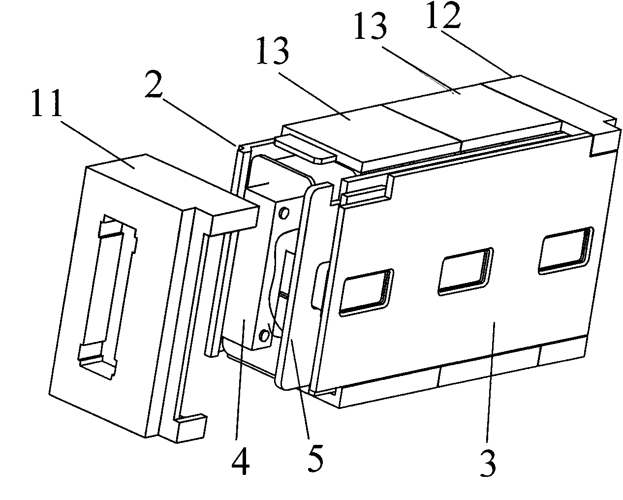
图3是图2中第一支架11的结构放大图;Fig. 3 is an enlarged view of the structure of the
图4是图2中第二支架12的结构放大图;Fig. 4 is the structure enlarged view of the
图5是图2中第三支架13的结构放大图;Fig. 5 is the enlarged view of the structure of the
图6是图2中第一挡板2的结构放大图;Figure 6 is an enlarged view of the structure of the
图7是图2中第二挡板3的结构放大图;Figure 7 is an enlarged view of the structure of the
图中:11.第一支架;111.侧壁;112.顶壁;113.底壁;1111.凹槽;1112.限位凹槽;1121.配合凸台;1122.限位凸台;1131.配合凹槽;1132限位凸台;In the figure: 11. the first bracket; 111. the side wall; 112. the top wall; 113. the bottom wall; 1111. the groove; 1112. the limit groove; .Matching groove; 1132 limit boss;
12.第二支架;121.侧壁;122.顶壁;123.底壁;1221.配合凹槽;1231配合凸台;12. Second bracket; 121. Side wall; 122. Top wall; 123. Bottom wall; 1221. Matching groove; 1231 Matching boss;
13第三支架;131.侧壁;132.顶壁;133.底壁;1311.限位凹槽;1321配合凸台;1322.配合凹槽;1331.限位凹槽;1332.配合凸台;13 third bracket; 131. side wall; 132. top wall; 133. bottom wall; 1311. limit groove; 1321 matching boss; 1322. matching groove; ;
2.第一挡板;21.底壁;211.凸台;212.通槽;213.限位凸台;2. The first baffle; 21. Bottom wall; 211. Boss; 212. Through groove; 213. Limiting boss;
3.第二挡板;31.底壁;312.通槽;313.固定凸台;314.限位凸台;3. Second baffle; 31. Bottom wall; 312. Through groove; 313. Fixed boss; 314. Limit boss;
4.互感器;5.电路板。4. Transformer; 5. Circuit board.
具体实施方式:Detailed ways:
如图1、2所示,电子脱扣器支架由第一挡板2、第二挡板3、第一支架11、第二支架12和至少两个第三支架13组成,第一挡板2和第二挡板3分别固定设置于电子脱扣器支架的两侧,即连接在第一支架11、第二支架12和第三支架13的两侧,第一挡板2和第二挡板3由塑料材料注塑或其它加工方式形成。As shown in Figures 1 and 2, the bracket of the electronic trip unit is composed of a
如图3所示,第一支架11由侧壁111和沿侧壁111两端同向延伸长度相同的顶壁112和底壁113形成的U型结构,在侧壁111上具有一凹槽1111,该凹槽1111可为通槽或盲槽,该凹槽1111轮廓与互感器4的外形轮廓相配以固定互感器4。靠近侧壁111一端具有一限位凹槽1112,该限位凹槽1112用于定位和固定第一挡板2至互感器支架上。在顶壁112上具有一配合凸台1121和一限位凸台1122。在底壁113上具有一配合凹槽1131和限位凸台1132。限位凸台1122和限位凸台1132定位和固定第二挡板3至互感器支架上。在第二支架12和第三支架13上设有与第一支架11的配合凸台1121、配合凹槽1131相配的配合凹槽1221和配合凸台1231以形成凹凸配合。As shown in FIG. 3 , the
如图4,第二支架12与第一支架11结构大致对称,具有一侧壁121、一顶壁122和一底壁123,呈U形,侧壁121、顶壁122、底壁123上的特征与第一支架11上相对应的特征相同;所不同的是顶壁122上具有配合凹槽1221和底壁123上具有配合凸台1231,与第一支架顶壁112上的配合凸台1121和底壁113上的配合凹槽1131相对应配合。As shown in Figure 4, the
如图5,第三支架13具有侧壁131和沿侧壁131两端向两侧延伸的顶壁132和底壁133,使所述第三支架13呈“工”型结构,在第三支架13“工”型结构侧壁131内腔两个大面上具有与第一支架11、第二支架12侧壁上限位凹槽相对应的限位凹槽1311,这两个限位凹槽1311深度之和应小于侧壁131的厚度,以保证不构成通槽。在顶壁132延伸的两端具有一配合凸台1321和一配合凹槽1322。在底壁133两端同样具有一配合凸台1332和一限位凹槽1331。第三支架13的顶壁132和底壁133上的配合凸台和配合凹槽分别与第一、第二支架11、12上顶壁、底壁上的配合凸台、配合凹槽相配以形成凹凸配合。As shown in Fig. 5, the
如图6,第一挡板2具有底壁21和沿底壁21垂直方向延伸一定长度的凸台211,使第一挡板2呈T形,在底壁21凸台位置开设有一通槽212,该通槽尺寸应使该凸台211有一定的壁厚以保证凸台的机械强度,使凸台不会断裂,在底壁21的两侧各有一限位凸台213,该限位凸台213与互感器支架的限位凹槽配合以固定和连接第一挡板2到互感器支架上。As shown in Figure 6, the
如图7所示,第二挡板3具有底壁31和在底壁31上分布的通槽312,所述通槽312与第一挡板2上的凸台211相对应配合,在底壁31上具有若干个固定凸台313,所述固定凸台313用于通过螺钉将线路板5连结到第二挡板3上。在底壁31两侧各具有至少一个限位凸台314,与互感器支架上的限位凹槽相配合以固定和连结第二挡板3至互感器支架上。As shown in Figure 7, the
所述电子脱扣器的安装方式为:互感器支架的第一、第二支架11、12和至少两个第三支架13包络互感器4以左右拼装方式连结到一起,第一挡板2通过其底壁21两端的限位凸台213与互感器支架上的限位凹槽1112、1212、1312相配,以连结第一挡板2至互感器支架,第二挡板3通过其底壁31两端的限位凸台314与互感器支架上的限位凸台1132、1232、1332交差配合,以将第一挡板2连结至互感器支架。The installation method of the electronic release is as follows: the first and
Claims (2)
Priority Applications (1)
| Application Number | Priority Date | Filing Date | Title |
|---|---|---|---|
| CN200910263145XA CN101710552B (en) | 2009-12-17 | 2009-12-17 | Electronic release bracket of electronic low pressure circuit breaker |
Applications Claiming Priority (1)
| Application Number | Priority Date | Filing Date | Title |
|---|---|---|---|
| CN200910263145XA CN101710552B (en) | 2009-12-17 | 2009-12-17 | Electronic release bracket of electronic low pressure circuit breaker |
Publications (2)
| Publication Number | Publication Date |
|---|---|
| CN101710552A CN101710552A (en) | 2010-05-19 |
| CN101710552B true CN101710552B (en) | 2012-05-02 |
Family
ID=42403332
Family Applications (1)
| Application Number | Title | Priority Date | Filing Date |
|---|---|---|---|
| CN200910263145XA Active CN101710552B (en) | 2009-12-17 | 2009-12-17 | Electronic release bracket of electronic low pressure circuit breaker |
Country Status (1)
| Country | Link |
|---|---|
| CN (1) | CN101710552B (en) |
Families Citing this family (1)
| Publication number | Priority date | Publication date | Assignee | Title |
|---|---|---|---|---|
| CN110556270A (en) * | 2019-09-12 | 2019-12-10 | 宏秀电气有限公司 | Special-shaped plate mounting structure for interphase shell of high-voltage circuit breaker and high-voltage circuit breaker |
-
2009
- 2009-12-17 CN CN200910263145XA patent/CN101710552B/en active Active
Also Published As
| Publication number | Publication date |
|---|---|
| CN101710552A (en) | 2010-05-19 |
Similar Documents
| Publication | Publication Date | Title |
|---|---|---|
| WO2017124779A1 (en) | Novel pole-mounted circuit breaker | |
| CN102142339A (en) | Miniature circuit breaker with current leakage protector | |
| CN107968016A (en) | A kind of pole that can improve electrical insulation properties | |
| CN100446149C (en) | Leakage circuit breakers | |
| US8174805B2 (en) | Residual current device | |
| CN102129937B (en) | Controller structure of electronic low-voltage circuit breaker | |
| CN101710552B (en) | Electronic release bracket of electronic low pressure circuit breaker | |
| CN101728126A (en) | Electronic leakage protector | |
| CN102054635B (en) | Leakage breaker | |
| CN204348640U (en) | Residual current action breaker | |
| RU2541517C2 (en) | Automatic circuit breaker | |
| CN213752591U (en) | Multifunctional intelligent circuit breaker | |
| CN211529901U (en) | Small-sized circuit breaker | |
| CN107993880A (en) | A kind of pole with current-taking function | |
| CN209497146U (en) | A kind of outdoor water-proof power supply box | |
| CN202564798U (en) | Intelligent harmonic and arc extinction switch cabinet | |
| CN107452561A (en) | A kind of Aftercurrent protecting equipment | |
| CN101699606B (en) | Electronic transducer bracket of low-voltage circuit breaker | |
| CN223757472U (en) | Circuit breaker assembly | |
| CN109802316A (en) | A kind of outdoor water-proof power supply box | |
| TWI884468B (en) | Multifunctional protection socket | |
| CN202816841U (en) | Residual current operated circuit-breaker with film cable structure | |
| CN203707734U (en) | Molded case circuit breaker grounding protection device in the main circuit of power distribution device | |
| CN201514905U (en) | Electronic transformer support of low-voltage circuit breaker | |
| CN201540859U (en) | Circuit Breaker Terminal Connections and Circuit Breakers |
Legal Events
| Date | Code | Title | Description |
|---|---|---|---|
| C06 | Publication | ||
| PB01 | Publication | ||
| C10 | Entry into substantive examination | ||
| SE01 | Entry into force of request for substantive examination | ||
| C14 | Grant of patent or utility model | ||
| GR01 | Patent grant | ||
| ASS | Succession or assignment of patent right |
Owner name: ZHENJIANG POWER SUPPLY COMPANY, JIANGSU PROV. POWE Effective date: 20140821 |
|
| C41 | Transfer of patent application or patent right or utility model | ||
| TR01 | Transfer of patent right |
Effective date of registration: 20140821 Address after: 212132 mechanical and Electrical Industrial Park, Dagang East Road, Dagang New District, Zhenjiang, Jiangsu, Zhenjiang A5 Patentee after: Jiangsu Phono Electric Co.,Ltd. Patentee after: JIANGSU ZHENJIANG ELECTRIC POWER SUPPLY Corp. Address before: 212132 mechanical and Electrical Industrial Park, Dagang East Road, Dagang New District, Zhenjiang, Jiangsu, Zhenjiang A5 Patentee before: Jiangsu Phono Electric Co.,Ltd. |
|
| CP01 | Change in the name or title of a patent holder | ||
| CP01 | Change in the name or title of a patent holder |
Address after: 212132 mechanical and Electrical Industrial Park, Dagang East Road, Dagang New District, Zhenjiang, Jiangsu, Zhenjiang A5 Patentee after: Jiangsu Phono Electric Co.,Ltd. Patentee after: ZHENJIANG POWER SUPPLY COMPANY, STATE GRID JIANGSU ELECTRIC POWER Co. Address before: 212132 mechanical and Electrical Industrial Park, Dagang East Road, Dagang New District, Zhenjiang, Jiangsu, Zhenjiang A5 Patentee before: Jiangsu Phono Electric Co.,Ltd. Patentee before: JIANGSU ZHENJIANG ELECTRIC POWER SUPPLY Corp. Address after: 212132 mechanical and Electrical Industrial Park, Dagang East Road, Dagang New District, Zhenjiang, Jiangsu, Zhenjiang A5 Patentee after: Jiangsu Phono Electric Co.,Ltd. Patentee after: STATE GRID JIANGSU ELECTRIC POWER Co.,Ltd. ZHENJIANG POWER SUPPLY BRANCH Address before: 212132 mechanical and Electrical Industrial Park, Dagang East Road, Dagang New District, Zhenjiang, Jiangsu, Zhenjiang A5 Patentee before: Jiangsu Phono Electric Co.,Ltd. Patentee before: ZHENJIANG POWER SUPPLY COMPANY, STATE GRID JIANGSU ELECTRIC POWER Co. |
|
| TR01 | Transfer of patent right | ||
| TR01 | Transfer of patent right |
Effective date of registration: 20220301 Address after: 212132 mechanical and Electrical Industrial Park, Dagang East Road, Dagang New District, Zhenjiang, Jiangsu, Zhenjiang A5 Patentee after: Jiangsu Phono Electric Co.,Ltd. Address before: 212132 mechanical and Electrical Industrial Park, Dagang East Road, Dagang New District, Zhenjiang, Jiangsu, Zhenjiang A5 Patentee before: Jiangsu Phono Electric Co.,Ltd. Patentee before: STATE GRID JIANGSU ELECTRIC POWER Co.,Ltd. ZHENJIANG POWER SUPPLY BRANCH |
|
| TR01 | Transfer of patent right | ||
| TR01 | Transfer of patent right |
Effective date of registration: 20220524 Address after: 212132 No. 97, Wufengshan Road, Dagang, New District, Zhenjiang City, Jiangsu Province Patentee after: Huineng low voltage electric appliance (Jiangsu) Co.,Ltd. Address before: 212132 mechanical and Electrical Industrial Park, Dagang East Road, Dagang New District, Zhenjiang, Jiangsu, Zhenjiang A5 Patentee before: Jiangsu Phono Electric Co.,Ltd. |
|
| CP01 | Change in the name or title of a patent holder | ||
| CP01 | Change in the name or title of a patent holder |
Address after: 212132 No. 97, Wufengshan Road, Dagang, New District, Zhenjiang City, Jiangsu Province Patentee after: Eaton Huineng low voltage electrical appliances (Jiangsu) Co.,Ltd. Address before: 212132 No. 97, Wufengshan Road, Dagang, New District, Zhenjiang City, Jiangsu Province Patentee before: Huineng low voltage electric appliance (Jiangsu) Co.,Ltd. |