CN101689471A - Compact fluorescent lamp with outer envelope and method for manufacturing - Google Patents
Compact fluorescent lamp with outer envelope and method for manufacturing Download PDFInfo
- Publication number
- CN101689471A CN101689471A CN200880024272A CN200880024272A CN101689471A CN 101689471 A CN101689471 A CN 101689471A CN 200880024272 A CN200880024272 A CN 200880024272A CN 200880024272 A CN200880024272 A CN 200880024272A CN 101689471 A CN101689471 A CN 101689471A
- Authority
- CN
- China
- Prior art keywords
- discharge tube
- outer envelope
- fluorescent lamp
- guard shield
- compact fluorescent
- Prior art date
- Legal status (The legal status is an assumption and is not a legal conclusion. Google has not performed a legal analysis and makes no representation as to the accuracy of the status listed.)
- Pending
Links
- 238000000034 method Methods 0.000 title claims abstract description 8
- 238000004519 manufacturing process Methods 0.000 title abstract description 16
- 239000000463 material Substances 0.000 claims abstract description 21
- 239000011521 glass Substances 0.000 claims abstract description 7
- OAICVXFJPJFONN-UHFFFAOYSA-N Phosphorus Chemical compound [P] OAICVXFJPJFONN-UHFFFAOYSA-N 0.000 claims abstract description 6
- 239000011248 coating agent Substances 0.000 claims abstract description 4
- 238000000576 coating method Methods 0.000 claims abstract description 4
- 238000012423 maintenance Methods 0.000 claims description 36
- 230000007246 mechanism Effects 0.000 claims description 35
- NJPPVKZQTLUDBO-UHFFFAOYSA-N novaluron Chemical compound C1=C(Cl)C(OC(F)(F)C(OC(F)(F)F)F)=CC=C1NC(=O)NC(=O)C1=C(F)C=CC=C1F NJPPVKZQTLUDBO-UHFFFAOYSA-N 0.000 claims description 17
- 238000003780 insertion Methods 0.000 claims description 3
- 230000037431 insertion Effects 0.000 claims description 3
- 229910052751 metal Inorganic materials 0.000 claims description 2
- 239000002184 metal Substances 0.000 claims description 2
- 239000012858 resilient material Substances 0.000 claims description 2
- 238000010586 diagram Methods 0.000 description 7
- 230000005540 biological transmission Effects 0.000 description 5
- 239000007789 gas Substances 0.000 description 5
- 229910052698 phosphorus Inorganic materials 0.000 description 5
- 239000011574 phosphorus Substances 0.000 description 5
- 239000000975 dye Substances 0.000 description 4
- 238000007789 sealing Methods 0.000 description 4
- 230000008901 benefit Effects 0.000 description 3
- 230000008859 change Effects 0.000 description 3
- 150000003017 phosphorus Chemical class 0.000 description 3
- XKRFYHLGVUSROY-UHFFFAOYSA-N Argon Chemical compound [Ar] XKRFYHLGVUSROY-UHFFFAOYSA-N 0.000 description 2
- 238000007599 discharging Methods 0.000 description 2
- 230000010358 mechanical oscillation Effects 0.000 description 2
- 230000005855 radiation Effects 0.000 description 2
- 230000008485 antagonism Effects 0.000 description 1
- 229910052786 argon Inorganic materials 0.000 description 1
- 230000008878 coupling Effects 0.000 description 1
- 238000010168 coupling process Methods 0.000 description 1
- 238000005859 coupling reaction Methods 0.000 description 1
- 238000013016 damping Methods 0.000 description 1
- 230000005611 electricity Effects 0.000 description 1
- 230000007613 environmental effect Effects 0.000 description 1
- 230000002349 favourable effect Effects 0.000 description 1
- 230000006872 improvement Effects 0.000 description 1
- 238000009413 insulation Methods 0.000 description 1
- 238000004020 luminiscence type Methods 0.000 description 1
- QSHDDOUJBYECFT-UHFFFAOYSA-N mercury Chemical compound [Hg] QSHDDOUJBYECFT-UHFFFAOYSA-N 0.000 description 1
- 229910052753 mercury Inorganic materials 0.000 description 1
- 230000004048 modification Effects 0.000 description 1
- 238000012986 modification Methods 0.000 description 1
- 238000012856 packing Methods 0.000 description 1
- 230000001105 regulatory effect Effects 0.000 description 1
- 230000000717 retained effect Effects 0.000 description 1
Images


Classifications
-
- H—ELECTRICITY
- H01—ELECTRIC ELEMENTS
- H01J—ELECTRIC DISCHARGE TUBES OR DISCHARGE LAMPS
- H01J9/00—Apparatus or processes specially adapted for the manufacture, installation, removal, maintenance of electric discharge tubes, discharge lamps, or parts thereof; Recovery of material from discharge tubes or lamps
- H01J9/24—Manufacture or joining of vessels, leading-in conductors or bases
- H01J9/245—Manufacture or joining of vessels, leading-in conductors or bases specially adapted for gas discharge tubes or lamps
- H01J9/247—Manufacture or joining of vessels, leading-in conductors or bases specially adapted for gas discharge tubes or lamps specially adapted for gas-discharge lamps
-
- H—ELECTRICITY
- H01—ELECTRIC ELEMENTS
- H01J—ELECTRIC DISCHARGE TUBES OR DISCHARGE LAMPS
- H01J61/00—Gas-discharge or vapour-discharge lamps
- H01J61/02—Details
- H01J61/30—Vessels; Containers
- H01J61/32—Special longitudinal shape, e.g. for advertising purposes
- H01J61/327—"Compact"-lamps, i.e. lamps having a folded discharge path
-
- H—ELECTRICITY
- H01—ELECTRIC ELEMENTS
- H01J—ELECTRIC DISCHARGE TUBES OR DISCHARGE LAMPS
- H01J61/00—Gas-discharge or vapour-discharge lamps
- H01J61/02—Details
- H01J61/30—Vessels; Containers
- H01J61/34—Double-wall vessels or containers
-
- H—ELECTRICITY
- H01—ELECTRIC ELEMENTS
- H01J—ELECTRIC DISCHARGE TUBES OR DISCHARGE LAMPS
- H01J61/00—Gas-discharge or vapour-discharge lamps
- H01J61/02—Details
- H01J61/56—One or more circuit elements structurally associated with the lamp
-
- Y—GENERAL TAGGING OF NEW TECHNOLOGICAL DEVELOPMENTS; GENERAL TAGGING OF CROSS-SECTIONAL TECHNOLOGIES SPANNING OVER SEVERAL SECTIONS OF THE IPC; TECHNICAL SUBJECTS COVERED BY FORMER USPC CROSS-REFERENCE ART COLLECTIONS [XRACs] AND DIGESTS
- Y02—TECHNOLOGIES OR APPLICATIONS FOR MITIGATION OR ADAPTATION AGAINST CLIMATE CHANGE
- Y02B—CLIMATE CHANGE MITIGATION TECHNOLOGIES RELATED TO BUILDINGS, e.g. HOUSING, HOUSE APPLIANCES OR RELATED END-USER APPLICATIONS
- Y02B20/00—Energy efficient lighting technologies, e.g. halogen lamps or gas discharge lamps
Abstract
A compact fluorescent lamp comprises a discharge tube arrangement with at least one discharge tube (5). The tube is formed of glass, encloses a discharge, volume filled with a discharge gas and has afluorescent phosphor coating disposed on the inner surface of' the tube. The tube forms a continuous arc path and is provided with electrodes disposed at each end of the arc path. The lamp also comprises a ballast circuit (7) mounted on a printed circuit board (9), which is oriented in a plane substantially parallel to the principal axis of the lamp. The ballast circuit is connected to the electrodes by lead-in wires and to a supply voltage by lead-out wires and controls the current in the tube. A bulb shaped outer envelope (2) has a ' substantially spherical portion (3) enclosing at least a part of the tube arrangement and an elongated end portion (4) enclosing at least the ballast circuit. The end portion of the outer envelope having an open end on a base side is closed and terminated bya closing means (11) of a material compatible with the material of the outer envelope. The ballast circuit and the discharge tube arrangement are held within the outer envelope and relative to each other in a predetermined position by a holding and protecting shield (20) being oriented in a plane substantially perpendicular to the principal axis of the lamp and comprising a receiving and fixing portion for the discharge tube and the printed circuit board of the ballast circuit. A method for manufacturing a compact fluorescent lamp as described above is also disclosed. In the proposed method,the ballast circuit and the discharge tube arrangement are inserted into and attached to a holding and protecting shield.
Description
Invention field
[0001] the present invention relates to compact fluorescent lamp (CFL), and more particularly relate to the compact fluorescent lamp that can replace general incandescent lamp.Even more specifically, the present invention relates to have the low-pressure compact fluorescent lamps of outer envelope and the ballast circuit in outer envelope.
Background of invention
[0002] present, most of known and low-pressure discharge lamps commercially available acquisition are so-called compact fluorescent lamps.Decision replaces the incandescent lamp that is used for wide industrial field and domestic. applications with these lamps.The major advantage of these lamps is that power consumption is low and the life-span is long.But the shortcoming of CFL is that its price is high relatively and length dimension is big.Propose many structures and solved length dimension problem.Such solution comprises multiple-string hookup and coil device.
[0003] US 4,527, and 089 discloses a kind of compact fluorescent lamp (CFL) that mechanically forms assembly and insert a plurality of independent pipe in the outer envelope that comprises.The pipe of independent opening is connected to each other by arc light (arc) guide, to form continuous arc path.Outer envelope has cylinder form, its sealing ground sealing, and comprise that arc light produces and keep medium, for example mercury and argon atmospher.Pass the horn mouth of the potted component that is used as cylindrical outer envelope as the fluorescent lamp wire guide of lead-in.The outside that provides the ballast circuit of energy to be positioned at outer envelope for fluorescent lamp, and therefore ballast circuit needs special contact element and device.
[0004] US 5,691, and 598 have described a kind of fluorescent lamp that has thermal heat shield between fluorescent tube and ballast circuit.This fluorescent lamp comprises fluorescent tube and the first power transmission mechanism and the second power transmission mechanism of electrical power is provided at the place, end of fluorescent tube, for the packing material in the fluorescent tube.Also comprised the thermal heat shield that the first power transmission mechanism and ballast circuit are separated, ballast circuit is supplied power to the first power transmission mechanism, and has the life-span that becomes quite low when its operating temperature increases.This thermal heat shield is configured such that its any neighbouring part with thermal radiation reflected back first power transmission mechanism and fluorescent tube, so that do not compare with there being heat shield, makes the operating temperature of ballast circuit reduce more than about one degree centigrade.But this thermal heat shield only is configured for using in having the CFL that is included in the ballast circuit in the housing that does not have outer envelope.
[0005] U.S. Patent No. 6,604, and 155 disclose a kind of fluorescent lamp that has outer envelope, and this outer envelope has the external shape of the incandescent lamp on Edison's type pedestal of standard.Discharge tube is coiled into around the axis of ladle cover and coils, and discharge tube is arranged in the outer envelope.Ballast also is arranged in the outer envelope.Heat shield is arranged between lamp and the ballast, so that lamp and ballast are isolated on calorifics, the heat from lamp can influence ballast sharply whereby.Though this lamp is provided with integrated ballast in outer envelope inside, owing to used the heat shield that is arranged between lamp and the ballast, so may produce serious difficulty at production period.This document is not open, and does not therefore know according to this document lamp and ballast circuit are how to locate and be fixed on outer envelope inside yet, and between lamp electrode and the ballast circuit or the electrical connection between ballast circuit and the pedestal how to set up.
[0006] need have such compact fluorescent lamp of the integrated ballast of bulbous outer envelope and outer envelope inside: this compact fluorescent lamp is provided with such mechanism; this mechanism is used for ballast circuit and discharge tube arrangement are remained in the outer envelope; and they relative to each other are held in a predetermined position, and it provide the mechanical protection to anti-vibration simultaneously.Need allow more easily to make lamp and therefore the improved structure of more cheap CFL is provided.Also need so improved production method: it is easy to combine with traditional manufacturing step, and therefore compatible with production in enormous quantities.Attempt to provide the compact fluorescent lamp structure of easily supporting dissimilar discharge tube structures.
Summary of the invention
[0007] in one exemplary embodiment of the present invention, provides a kind of compact fluorescent lamp that comprises discharge tube arrangement with at least one discharge tube.Pipe is made by glass, surrounds and is filled with the discharge volume of discharge gas, and have the fluorescence phosphor coating on the inner surface that is arranged on pipe.Pipe forms continuous arc path, and is provided with the electrode at each place, end that is arranged on arc path.Lamp also comprises the ballast circuit that is installed on the printed circuit board (PCB), and this ballast circuit is directed in the plane of the main shaft that is basically parallel to lamp.Ballast circuit is connected on the electrode by lead-in, and is connected on the supply power voltage by lead-out wire, and the electric current in the control valve.Bulb shaped outer envelope has the part of the substantially spherical of at least a portion of surrounding pipe unit, and the end sections that surrounds the elongation of ballast circuit at least.On base side, have close mechanism closure and termination that the end sections of the outer envelope of open end is made by the material compatible with the material of outer envelope.Ballast circuit and discharge tube arrangement are by keeping and protecting guard shield to remain in the outer envelope; and relative to each other be held in a predetermined position; this maintenance and protection guard shield are directed in the plane of the main shaft that is basically perpendicular to lamp, and comprise the reception and the standing part of the printed circuit board (PCB) that is used for discharge tube and ballast circuit.
[0008] in the exemplary embodiment of the present invention aspect another, a kind of method that is used to make compact fluorescent lamp has been proposed.This method comprises the following steps: to provide the part that comprises substantially spherical and by the outer envelope of the end sections of the elongation of the open end termination on the base side.The close mechanism made from the material compatible with the material of outer envelope comes the open end of the elongated portion of closed and termination ladle cover.Close mechanism also comprises the tubular opening of the lead-out wire between the contact terminal that is used to receive and guide ballast circuit and base shell.Cut into the top part and, make the ladle cover separated into two parts by the circumference in the plane of the main shaft that is basically perpendicular to lamp by the bottom part of the close mechanism termination at base side place.Maintenance and protection guard shield are attached on the printed circuit board (PCB) of ballast circuit, and discharge tube arrangement inserts in this maintenance and the protection guard shield.The lead-in of discharge tube arrangement and lead-out wire are connected on the corresponding tie point of ballast circuit, thereby the lamp ballast assembly is provided.The lamp ballast assembly is introduced in the bottom part of ladle cover, and the tubular opening of close mechanism is passed in the lead-out wire guiding.Two divided portion of ladle cover come in contact each other along separator bar.The top part and the bottom part that connect and seal ladle cover along separator bar.Ladle cover is provided with pedestal, and lead-out wire is connected on the contact terminal of pedestal.
[0009] disclosed compact fluorescent lamp provide to the CFL member firmly and the mechanical fixation of vibration damping, with and the manufacture method simplified.By using according to maintenance of the present invention and protection guard shield, ballast circuit and discharge tube arrangement remain in the outer envelope, and relative to each other are held in a predetermined position.Another advantage that is realized by the present invention is, has protected ballast circuit not to be subjected to the influence of applied heat during two divided portion that connect outer envelope effectively.Can be retained in the most of steps in the employed continuous manufacturing step during the production conventional incandescent, thereby provide better condition for production in enormous quantities.Use horn mouth with discharge pipe, the possibility of the production line that is used to make conventional incandescent is provided, this has also reduced production cost, particularly when comparing with other lamp that seems similar GLS (general lighting service).Another advantage of this lamp is with bulb-shaped incandescent lamps machinery and electric compatibility are completely arranged, and this makes it become alternative lamp efficiently.The lamp that is proposed provides the protection of the certain level that overcomes environmental load owing to outer envelope.
The accompanying drawing summary
Now with reference to accompanying drawing the present invention is described in detail, wherein:
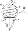
Fig. 1 is the partial cross section's perspective view that has shown one embodiment of the present of invention;
Fig. 2 is the partial cross section's front view according to embodiments of the invention shown in Figure 1;
Fig. 3 is the partial side view in cross section according to embodiments of the invention shown in Figure 1;
Fig. 4 is according to the perspective view of one exemplary embodiment of the present invention, the maintenance that is used for lamp and protection guard shield;
Fig. 5 is according to the vertical view of one exemplary embodiment of the present invention, the maintenance that is used for lamp and protection guard shield;
Fig. 6 is the schematic diagram that outer envelope is provided when making lamp;
Fig. 7 is the schematic diagram that makes the outer envelope closure when making lamp;
Fig. 8 is the schematic diagram that when making lamp outer envelope is separated;
Fig. 9 is the schematic diagram that discharge tube arrangement and maintenance and protection guard shield are connected with ballast circuit;
Figure 10 is the schematic diagram that inserts the lamp ballast assembly when making lamp;
Figure 11 is the schematic diagram that connects and seal two parts of ladle cover when making lamp;
Figure 12 is the schematic diagram that pedestal and contact terminal are provided for the closed ends of ladle cover when making lamp.
Detailed Description Of The Invention
[0010], shown low-pressure discharge lamp 1 at first referring to Fig. 1 to 3.This lamp is the discharge lamp with luminescence with the outer envelope 2 that surrounds discharge tube arrangement 5 and ballast circuit 7.Outer envelope 2 has spherical part 3 and has the longitudinal component 4 of the neck part 10 of the opening that is connected on the pedestal 6, and defines main shaft 13.Fig. 2 shown the threaded neck part 10 that is used to be connected on the spiral type pedestal ', and Fig. 3 has shown the neck part 10 that is used to be connected on the bayonet socket pedestal.Outer envelope is cut into two parts, and at line of cut 12 places separately, so that make ballast circuit 7 and discharge tube arrangement 5 can insert and be connected to outer envelope 2 inside, can be described in more detail below.Discharge tube arrangement 5 can comprise single discharge tube or a plurality of elongated discharge tube.Discharge tube is made by glass, surrounds and is filled with the discharge volume of discharge gas, and have the fluorescence phosphor coating on the inner surface that is arranged on pipe.The end of pipe seals in airtight mode.Pipe forms continuous arc path, electrode and be connected to the place, end that lead-in 17 on the electrode is positioned at this arc path.The lead-in 17 of discharge tube arrangement is connected on the ballast circuit 7, with the electric current in the control discharge tube.Ballast circuit 7 further is connected on the supply power voltage by lead-out wire 18, and this lead-out wire 18 is connected on the contact terminal 8 in the lamp socket 6.Shown in Fig. 2 and 3, close mechanism 11 closures and termination that the open end of the neck part 10 of outer envelope 2 is made by the material identical or compatible with the material of outer envelope.Close mechanism 11 is provided with tubular opening 19.Lead-out wire 18 separates each other, and tubular opening 19 is passed in guiding and to motor seat 6, by socket lamp is connected on the supply power voltage.Lamp socket is configured to so that be suitable for socket, and socket can be the socket of any traditional type that is generally used for lamp.Lamp socket can be configured to so that be assemblied in spiral type socket or the aligning plug.
[0011] ballast circuit 7 is installed on the printed circuit board (PCB) (PCB) 9, and it has the orientation of the main shaft 13 that is basically parallel to lamp.The edge of printed circuit board (PCB) 9 of carrying ballast circuit 7 advantageously has the similar border form in longitudinal section to the wall of the outer envelope 2 that obtains from the plane of the main shaft 13 that is parallel to lamp 1, but has the skew that size limited, as from Fig. 3, seeing best by close mechanism and discharge tube.
[0012] close mechanism 11 that is used for compact fluorescent lamp of the present invention comprises the horn mouth on the open end of the neck part 10 that is connected to ladle cover, and has formed and extend through this horn mouth to receive and the discharge pipe of the tubular opening 19 of the power outlet 18 of guiding ballast circuit.Lead-out wire 18 separates each other, and tubular opening 19 is passed in guiding and to motor seat 6, by socket lamp is connected on the supply power voltage.
[0013] outer envelope 2 is made of two parts that the circumference 12 in the plane of the main shaft 13 that is basically perpendicular to lamp separates.These two parts comprise the top part of a part that is used to receive discharge tube arrangement 5, and the bottom part that is used to receive the remainder and the ballast circuit 7 of discharge tube arrangement 5.Two parts of this of ladle cover are connected and seal, to form uniform bulb shaped envelope 2.The wall that the circumference separator bar 12 of outer envelope 2 can preferably be in ladle cover has in the zone of substantially cylindrical form.In the embodiment shown, separator bar 12 is in the wideest location of the spherical part of outer envelope, so that use the big relatively discharge tube of the outer envelope internal capacity that can fill maximum.This helps to keep the relatively little size of conventional incandescent, and helps to realize the high relatively luminous output of big relatively discharge tube.The wideest zone of the substantially spherical part of outer envelope can comprise the cylindrical region that is enough to form separator bar 12.
[0014] in the embodiment shown, compact fluorescent lamp comprises such discharge tube arrangement 5, and this discharge tube arrangement 5 is the single pipes with straight substantially end region and the mid portion between end region.End region is in an end place of pipe unit, and parallel to each other substantially, and mid portion has and coils structure around the main shaft that is coiled in lamp.
[0015] or, discharge tube arrangement can be made of the straight duct member of the longitudinal axis with the main shaft that is basically parallel to fluorescent lamp, wherein Lin Jin duct member is connected to each other in the mode of series connection, to form continuous arc path.Depend on required output luminous intensity, feasible device also comprises the structure with two, four or six independent discharge tube members.Discharge tube arrangement also can comprise two independent elongated discharge tube members same length, that bend to U-shaped, and they are connected by bridgeware five, to form continuous arc path.Depend on required output luminous intensity, feasible device also comprises the structure with one or three the independent discharge tube that bends to U-shaped.The U-shaped discharge tube members can comprise the substantially parallel straight district and the crooked mesozone of the length that limits discharge tube arrangement.
[0016] each discharge tube surrounds the discharge volume that is filled with discharge gas.Discharge tube is tubulose substantially.In the embodiment shown, discharge tube is columniform, but also can select other suitable cross section.Usually, discharge tube is made by glass, but can not get rid of other suitable material.Preferably, mainly be to consider, but also in order to ensure discharging equably along its overall length in discharge tube, the wall thickness of discharge tube should be constant substantially from manufacture view.
[0017] for visible light is provided, the inner surface of discharge tube is coated with fluorescence phosphorus layer.This phosphorus layer is in the discharge volume of sealing.The component of this phosphorus layer is known per se.This phosphorus layer converts the UV radiation to visible light.Before the enclosed discharge channel phosphorus layer is being administered on the inner surface of discharge tube.
[0018] discharge tube arrangement 5 and printed circuit board (PCB) 9 are remained in the outer envelope by maintenance and protection guard shield 20, and relative to each other maintain, and keep and protection guard shield 20 orientation in the plane of the main shaft 13 that is basically perpendicular to lamp.Keep and keep guard shield 20 to comprise the reception and the standing part of the printed circuit board (PCB) 9 that is used for discharge tube arrangement 5 and ballast circuit 7, and provide and overcome adequately protecting of mechanical oscillation and impact.
[0019] describes as Figure 4 and 5; keep and protection guard shield 20 has such profile form: this profile form is basic identical with outer envelope 2 cross section profiles in the contact area that obtains from the plane of the main shaft 13 that is basically perpendicular to lamp, so as with the inwall coupling of outer envelope 2.Usually, bulbous envelope has almost circular cross sectional boundary, and therefore the profile of maintenance and protection guard shield 20 also has almost circular form.Keep and the protection guard shield is made by resilient material, and have diagonal-size (D), this diagonal-size (D) is greater than the internal diameter (d) of the outer envelope in the contact area, and axial force is provided when being on assembling or the final position at guard shield.In the embodiment shown in the Figure 4 and 5, keep having outward flange from guard shield and extend three projections 21 with the inner surface (with the dotted line demonstration) that contact outer envelope with protection guard shield 20.On each side of projection 21, slit 24 is arranged, so that improve its elasticity, but but the elasticity that the slit sufficient to guarantee is suitable on a side of projection 21.Certainly, the quantity of projection and form can change according to application.For the purpose of exemplary embodiment of the present invention, also can use the guard shield that does not have projection but have slit, perhaps (have) guard shield of at least two projections and each at least one slit of projection.In order to regulate axial force, can correspondingly select the length of the quantity of slit of quantity, each projection of projection and slit and extend beyond circular maintenance and the projection length at the edge of protection guard shield.When the quantity that increases projection, perhaps reduce the quantity of slit, when perhaps reducing the length of slit,, the edge that makes maintenance and protection guard shield will increase owing to being pressed against the axial force that produces on the convergent inwall of outer envelope.On the other hand,, perhaps increase the quantity of slit, when perhaps increasing the length of slit, will reduce owing to the edge that makes maintenance and protection guard shield is pressed against the axial force that produces on the convergent inwall of outer envelope when the quantity that reduces projection.
[0020] keep and protection guard shield 20 be used to receive and fixedly the reception and the standing part of discharge tube arrangement comprise almost circular opening 22.The almost circular opening 22 of maintenance and protection guard shield 20 has a projection 25 of extending towards the center of opening 22, and the slit 26 on each side of projection 25.Keep and protection guard shield 20 be used to receive and the almost circular opening 22 that keeps the discharge tube end at the diagonal-size at projection 25 places external diameter less than discharge tube.Can be according to protrusion by the section form of the end region of the discharge tube arrangement of maintenance and protection guard shield and form and the quantity that quantity is selected opening.And the quantity of projection and form can change according to application.Purpose for exemplary embodiment of the present invention, also can use the opening that does not have projection but have at least two slits that equally distribute along the edge of almost circular opening, perhaps (have) opening of at least two projections and each at least one slit of projection.If almost circular opening does not have projection, just the diameter of this opening must be chosen to protruding less than discharge tube by the external diameter in the end regions of guard shield.Can be by regulating the bed knife that applies by projection 25 with the above described similar mode of axial force that combines the projection 21 of guard shield.
[0021] keep and protection guard shield 20, be used to receive and the reception and the standing part of the printed circuit board (PCB) of fixed-ballast circuit comprise the elongated open 23 with resilient side component 27; side component 27 is towards each other; insert the printed circuit board (PCB) of ballast circuit with permission, and when inserting, fix this printed circuit board (PCB).Elongated open 23 by along the straight cuts material with produce vertical slit and at the place, end of vertical slit along two little slits of transverse cuts, be formed at keep and protection guard shield 20 in.Vertically the length dimension of slit and lateral slit will define the size and the intensity of flexible side component 27.
[0022] maintenance and protection guard shield can be made by metal or plastic material with sufficient intensity and flexibility.Outer envelope and close mechanism can be made by transparent or translucent glass or plastic material.
[0023] referring now to Fig. 6 to 12, will describe the step of producing such compact fluorescent lamp in further detail: this compact fluorescent lamp has the outer envelope that holds discharge tube arrangement and remained on the ballast circuit of ladle cover inside by maintenance and protection guard shield.In step 1, describe as Fig. 6, the outer envelope 2 of the end sections 4 with substantially spherical part 3 and elongation is provided.The end sections 4 of elongation has open end at neck part 10 places.In step 2, as shown in Figure 7, the open end of the end sections 4 of elongation is by close mechanism 11 closures and termination, and close mechanism 11 is made by the material identical or compatible with it with the material of ladle cover.Close mechanism 11 also comprises the tubular opening 19 that is used to make lead-out wire guiding that ballast and pedestal are coupled together to pass.Close mechanism 11 can be made of horn mouth and discharge pipe 14.After on the open end that close mechanism 11 is connected to ladle cover, utilize the tubular portion of cutting dyestuff (cutting dye) 30 cutting discharge pipes 14 in a distance, so that tubular opening 19 is provided near the horn section of close mechanism 11.Same feasible is that the length of discharge pipe 14 is chosen to so that be in during manufacture in the required scope, thereby and does not need to cut shortlyer.Discharge pipe also provides gas to be communicated with between the internal capacity of outer envelope and outside atmosphere, and in the time may discharging different gaseous products in outer envelope, this may be favourable during operation.
[0024] in the 3rd step, as shown in Figure 8, outer envelope 2 is cut into two parts with cutting dyestuff 30.This can rotate preferably and realize by make ladle cover center on its main shaft in time in the cutting position of ladle cover being put into cutting dyestuff (itself also rotation).The separator bar 12 of Chan Shenging has circumference or circular form in the plane of the main shaft that is basically perpendicular to lamp by this way.Removed top part 31 from bottom part 41, this bottom part is held the close mechanism 11 that also comprises tubular opening 19.
[0025] in the 4th step (Fig. 9), discharge tube arrangement 5 inserts in maintenance and the protection guard shield 20, and the printed circuit board (PCB) of ballast circuit is inserted, and it is attached on maintenance and the protection guard shield.In order to reach this purpose, printed circuit board (PCB) 9 has extension 15 at the wide place, end relative with the narrow end in the neck part 10 that is assembled to outer envelope.The order of assembling these parts also may be selected to be at first and will keep and protect guard shield to be attached on the ballast circuit, and discharge tube arrangement is inserted in maintenance and the protection guard shield then.This simple insertion provides related parts relative to each other to fix required intensity.Perhaps, except the projection of guard shield, perhaps replace the projection of guard shield, also can use other fixed mechanism.Ballast circuit 7 is connected with discharge tube arrangement 5 by the mode of lead-in 17 with electricity, and is connected on the lead-out wire 18 of power supply, thereby lamp-ballast component is provided.It is that the insulation free end of wire rod is welded together with the wiring point of corresponding connector or ballast circuit that lead-in and lead-out wire are connected to a kind of feasible mode on the ballast.Though this step has been described as the 4th consecutive steps after the 3rd step, also can have carried out this step than commitment any of manufacturing.Important only is that the lamp ballast assembly is provided when outer envelope separates.
[0026] in the 5th step (Figure 10); also comprise in the bottom part 41 of the lamp-ballast component insertion outer envelope 2 that keeps and protect guard shield; till the inwall of printed circuit board (PCB) and outer envelope came in contact, outer envelope was by close mechanism 11 closures and the termination that comprise tubular opening 19.When in the bottom part 41 of lamp-ballast component being inserted outer envelope, lead-out wire 18 is guided through tubular opening 19, and keeps and the protection guard shield is pressed against at the taper region place on the inwall of outer envelope, thus the axial force that guard shield is lifted in the generation meeting.In order to resist this axial force, keep and fixing lead-out wire 18 with respect to close mechanism 11.
[0027] in the 6th step (Figure 11), the top part 31 and the bottom part 41 of outer envelope 2 linked again and seals.In order between the top of outer envelope 2 part 31 and bottom part 41, to realize firm mechanical connection or sealing, can use heater 32 that these two parts are welded together, this heater 32 can be gas heater etc.In the wideest zone of the spherical part of outer envelope, selected the position of the circumference separator bar of outer envelope; herein, wall is enough to protect ballast circuit not to be subjected to the big relatively distance of influence of the heat of heater 32 to have the form of substantially cylindrical at the printed circuit board (PCB) from the carrying ballast circuit.Maintenance between discharge tube and ballast circuit and protection guard shield provide extra heat protection.After finishing this step, can discharge lead-out wire 18, then, maintenance and protection guard shield move up and make discharge tube arrangement press the inwall of outer envelope.Like this, keep and the protection guard shield provides firm and resilient fixing to discharge tube and ballast circuit in outer envelope inside, and relative to each other firm and resilient fixing is provided, thereby and also provide the protection of antagonism mechanical oscillation and impact.
[0028] last, in the 7th step (Figure 12), finished compact fluorescent lamp with pedestal 6, pedestal 6 is used for lamp is connected to any tradition or standard socket that is screwed into type or bayonet type.In the example shown, as seeing in Figure 12, compact fluorescent lamp is provided with Edison's type pedestal 6.Lamp socket can any traditional mode, for example by bonding, condense or be threaded, be fixed on the neck part of elongated portion 4 of outer envelope 2.When using being threaded of Edison's type pedestal (Fig. 2), it can be screwed on the threaded neck part 10 of ladle cover.And the electrically contacting of contact terminal 8 of in this step, having set up the lead-out wire of power supply and pedestal 6.
[0029] discloses the present invention, still it will be apparent for a person skilled in the art that to the invention is not restricted to shown and disclosed embodiment, but other element, improvement and modification have been also within the scope of the invention with reference to accompanying drawing.For example, many other forms that are clear that ladle cover, discharge tube and pedestal also can be applicable to purpose of the present invention.For example, ladle cover can have sphere or T shape.The quantity of the discharge tube members in the lamp and form also can change according to the size or the power demand output of lamp.Also can select to be used to provide the base shell that is connected to the electrical connection on the power supply according to type any standard or off-gauge.
Claims (20)
1. compact fluorescent lamp comprises:
-discharge tube arrangement, at least one discharge tube that described discharge tube arrangement is made by glass forms, encirclement is filled with the discharge volume of discharge gas, and has the fluorescence phosphor coating on the inner surface that is arranged on described pipe, described pipe forms continuous arc path, and further is provided with the electrode at each place, end that is arranged on described arc path;
-be installed in the ballast circuit on the printed circuit board (PCB), described ballast circuit is directed in the plane of the main shaft that is basically parallel to described lamp, controlling the electric current in the described pipe, and be connected on the described electrode, and be connected on the supply power voltage by lead-out wire by lead-in;
-comprise the part of the substantially spherical that surrounds described discharge tube arrangement and surround the bulb shaped outer envelope of end sections of the elongation of described ballast circuit;
The described end sections of-described outer envelope has open end on base side;
Close mechanism closure and termination that-described open end is made by the material compatible with the material of described outer envelope;
-described ballast circuit and described discharge tube arrangement are by keeping and protecting guard shield to remain in the described outer envelope; and relative to each other be maintained on the precalculated position; described maintenance and protection guard shield are directed in the plane of the main shaft that is basically perpendicular to described lamp, and comprise the reception and the standing part of the printed circuit board (PCB) that is used for described discharge tube and described ballast circuit.
2. compact fluorescent lamp according to claim 1; it is characterized in that; described maintenance and protection guard shield are made by resilient material; and have diagonal-size (D), provide axial force on assembling and final position the time with the described guard shield of box lunch greater than the internal diameter (d) of the described outer envelope in the contact area.
3. compact fluorescent lamp according to claim 1 is characterized in that, described maintenance and protection guard shield have with contact area in the essentially identical profile form of cross section profile of described outer envelope.
4. compact fluorescent lamp according to claim 1 is characterized in that, described maintenance and protection guard shield have from the outward flange of described guard shield and extend at least two projections with the inner surface that contacts described outer envelope.
5. compact fluorescent lamp according to claim 4 is characterized in that, described maintenance and protection guard shield have slit at least one side of described projection.
6. compact fluorescent lamp according to claim 1 is characterized in that, the described reception and the standing part of described maintenance and protection guard shield comprise the almost circular opening that is used to receive and keep described discharge tube.
7. compact fluorescent lamp according to claim 6; it is characterized in that; the described almost circular opening of described maintenance and protection guard shield has at least one projection of extending towards the center of described opening; and the slit of at least one side of described projection, and the diagonal-size of described almost circular opening that is used to receive and keeps the described maintenance of described discharge tube and protection guard shield in described prominence the external diameter less than described discharge tube.
8. compact fluorescent lamp according to claim 6; it is characterized in that; the described almost circular opening of described maintenance and protection guard shield has at least two slits that equally distribute along the edge of described almost circular opening, and the diameter of described circular open that is used to receive and keeps the described maintenance of described discharge tube and protection guard shield is less than the external diameter of described discharge tube.
9. compact fluorescent lamp according to claim 1 is characterized in that, described maintenance and protection guard shield comprise elongated open, as the reception and the maintaining body of the printed circuit board (PCB) that is used for described ballast circuit.
10. compact fluorescent lamp according to claim 9; it is characterized in that; the described elongated open of described maintenance and protection guard shield has towards resilient side component each other, with the described printed circuit board (PCB) that allows to insert the printed circuit board (PCB) of described ballast circuit and be used for fixing insertion.
11. compact fluorescent lamp according to claim 1 is characterized in that, described maintenance and protection guard shield are made of metal.
12. compact fluorescent lamp according to claim 1 is characterized in that, described maintenance and protection guard shield are made by plastic material.
13. compact fluorescent lamp according to claim 1 is characterized in that, described close mechanism and described outer envelope are made by glass.
14. compact fluorescent lamp according to claim 1 is characterized in that, described close mechanism and described outer envelope are made by plastic material.
15. compact fluorescent lamp according to claim 1, it is characterized in that, described close mechanism comprises the horn mouth on the open end that is connected to described ladle cover, and forms and to extend through described horn mouth to receive and to guide the discharge pipe of tubular opening of the lead-out wire of described ballast circuit.
16. compact fluorescent lamp according to claim 1, it is characterized in that, described outer envelope is made of two parts that the circumference in the plane of the main shaft that is basically perpendicular to described lamp separates, described two parts comprise the top part of a part that is used to receive described discharge tube arrangement, and the bottom part that is used to receive the remainder and the described ballast circuit of described discharge tube arrangement, described two parts of described ladle cover are connected and seal, to form uniform bulb shaped envelope.
17. compact fluorescent lamp according to claim 16 is characterized in that, the described circumference separator bar of described outer envelope has in the zone of substantially cylindrical form at the wall of described ladle cover.
18. compact fluorescent lamp according to claim 1, it is characterized in that, described discharge tube arrangement is made of the single pipe with straight substantially end region and the mid portion between described end region, and described end region is in the place, an end of described pipe unit, and closer to each other, and described mid portion has the structure of coiling around the coiling of the main shaft of described lamp.
19. compact fluorescent lamp according to claim 1, it is characterized in that, described discharge tube arrangement is made of the straight duct member of the longitudinal axis with the main shaft that is basically parallel to described lamp, and contiguous duct member in series is connected to each other, to form continuous arc path.
20. a method that is used to make compact fluorescent lamp may further comprise the steps:
A) provide the part that comprises substantially spherical and by the outer envelope of the end sections of the elongation of the open end termination on the base side;
B) utilize the close mechanism of making by the material compatible to come the open end of the elongated portion of closure and the described ladle cover of termination, described close mechanism also to comprise to be used to the tubular opening of the lead-out wire between the contact terminal that receives and guide ballast circuit and base shell with the material of described outer envelope;
C) by the circumference in the plane of the main shaft that is basically perpendicular to described lamp cutting, described ladle cover is divided into the top part and at described base side place by described close mechanism termination and bottom part;
D) will keep and protect guard shield to be attached on the described ballast circuit, and described discharge tube arrangement will be inserted in described maintenance and the protection guard shield;
E) on the corresponding tie point that the lead-in and the described lead-out wire of described discharge tube arrangement is connected to described ballast circuit, thereby provide the lamp ballast assembly;
F) described lamp ballast assembly is introduced in the described bottom part of described ladle cover, and guided described lead-out wire to pass the tubular opening of described close mechanism;
G) along described separator bar the top part of separating and the bottom part of described ladle cover are come in contact each other;
H) connect and seal the described top part and the bottom part of described ladle cover along described separator bar;
I) provide pedestal for described ladle cover; And
J) described lead-out wire is connected on the contact terminal of described pedestal.
Applications Claiming Priority (5)
| Application Number | Priority Date | Filing Date | Title |
|---|---|---|---|
| HUP0700331 | 2007-05-10 | ||
| HU0700331A HU0700331D0 (en) | 2007-05-10 | 2007-05-10 | Compact fluorescent lamp with outer envelope and method for manufacturing |
| US11/837,858 US7459856B1 (en) | 2007-05-10 | 2007-08-13 | Compact fluorescent lamp with outer envelope and method for manufacturing |
| US11/837,858 | 2007-08-13 | ||
| PCT/US2008/060825 WO2008140894A1 (en) | 2007-05-10 | 2008-04-18 | Compact fluorescent lamp with outer envelope and method for manufacturing |
Publications (1)
| Publication Number | Publication Date |
|---|---|
| CN101689471A true CN101689471A (en) | 2010-03-31 |
Family
ID=89987504
Family Applications (1)
| Application Number | Title | Priority Date | Filing Date |
|---|---|---|---|
| CN200880024272A Pending CN101689471A (en) | 2007-05-10 | 2008-04-18 | Compact fluorescent lamp with outer envelope and method for manufacturing |
Country Status (10)
| Country | Link |
|---|---|
| US (1) | US7459856B1 (en) |
| EP (1) | EP2156463B1 (en) |
| JP (1) | JP2010527115A (en) |
| CN (1) | CN101689471A (en) |
| AT (1) | ATE527681T1 (en) |
| AU (1) | AU2008251722A1 (en) |
| CA (1) | CA2686607A1 (en) |
| HU (1) | HU0700331D0 (en) |
| PL (1) | PL2156463T3 (en) |
| WO (1) | WO2008140894A1 (en) |
Cited By (1)
| Publication number | Priority date | Publication date | Assignee | Title |
|---|---|---|---|---|
| CN102315082A (en) * | 2010-05-26 | 2012-01-11 | 通用电气公司 | The safeguard protection scheme that is used for compact fluorescent lamp |
Families Citing this family (32)
| Publication number | Priority date | Publication date | Assignee | Title |
|---|---|---|---|---|
| US20080265741A1 (en) * | 2007-04-29 | 2008-10-30 | Crystal Green Lighting Co., Ltd. | Semi-full helical luminous electronic energy-saving lamp |
| US7915826B2 (en) | 2008-07-29 | 2011-03-29 | General Electric Company | Electric lamp with inner assembly and outer bulb and method for manufacturing |
| US20100096971A1 (en) * | 2008-10-20 | 2010-04-22 | Chia-Chieh Liu | Oxidation resistant base of compact fluorescent lamp |
| HUP0900119A3 (en) * | 2009-02-27 | 2013-05-28 | Ge Hungary Zrt | Lamp with outer envelope and method for manufacturing the same |
| US20110089832A1 (en) * | 2009-10-20 | 2011-04-21 | Kelly Gregory J | Sealed outer envelope that houses a compact fluorescent lamp to prevent mercury vapor release to the environment in case of damage to the compact fluorescent lamp |
| US20110115372A1 (en) * | 2009-11-17 | 2011-05-19 | General Electric Company | Electric lamp with pin connectors and method of manufacture |
| CN102386048A (en) * | 2011-09-23 | 2012-03-21 | 陶国胜 | Double-filament ceiling lamp with double-ring lamp tube |
| CN103199002A (en) * | 2012-01-05 | 2013-07-10 | 苏州金三元照明电器有限公司 | Novel energy-saving fluorescent lamp |
| KR101365633B1 (en) * | 2012-02-10 | 2014-02-24 | 강성석 | Discharge lamp |
| KR101534324B1 (en) * | 2012-07-24 | 2015-07-07 | 강성진 | Discharge Lamp |
| US8872426B2 (en) | 2012-11-26 | 2014-10-28 | Lucidity Lights, Inc. | Arrangements and methods for triac dimming of gas discharge lamps powered by electronic ballasts |
| US9524861B2 (en) | 2012-11-26 | 2016-12-20 | Lucidity Lights, Inc. | Fast start RF induction lamp |
| US8941304B2 (en) | 2012-11-26 | 2015-01-27 | Lucidity Lights, Inc. | Fast start dimmable induction RF fluorescent light bulb |
| US9460907B2 (en) | 2012-11-26 | 2016-10-04 | Lucidity Lights, Inc. | Induction RF fluorescent lamp with load control for external dimming device |
| US9161422B2 (en) | 2012-11-26 | 2015-10-13 | Lucidity Lights, Inc. | Electronic ballast having improved power factor and total harmonic distortion |
| US8698413B1 (en) | 2012-11-26 | 2014-04-15 | Lucidity Lights, Inc. | RF induction lamp with reduced electromagnetic interference |
| US10529551B2 (en) | 2012-11-26 | 2020-01-07 | Lucidity Lights, Inc. | Fast start fluorescent light bulb |
| US9209008B2 (en) | 2012-11-26 | 2015-12-08 | Lucidity Lights, Inc. | Fast start induction RF fluorescent light bulb |
| US9129791B2 (en) | 2012-11-26 | 2015-09-08 | Lucidity Lights, Inc. | RF coupler stabilization in an induction RF fluorescent light bulb |
| US9305765B2 (en) | 2012-11-26 | 2016-04-05 | Lucidity Lights, Inc. | High frequency induction lighting |
| US20140375203A1 (en) | 2012-11-26 | 2014-12-25 | Lucidity Lights, Inc. | Induction rf fluorescent lamp with helix mount |
| US9245734B2 (en) | 2012-11-26 | 2016-01-26 | Lucidity Lights, Inc. | Fast start induction RF fluorescent lamp with burst-mode dimming |
| US9129792B2 (en) | 2012-11-26 | 2015-09-08 | Lucidity Lights, Inc. | Fast start induction RF fluorescent lamp with reduced electromagnetic interference |
| US10141179B2 (en) | 2012-11-26 | 2018-11-27 | Lucidity Lights, Inc. | Fast start RF induction lamp with metallic structure |
| US10128101B2 (en) | 2012-11-26 | 2018-11-13 | Lucidity Lights, Inc. | Dimmable induction RF fluorescent lamp with reduced electromagnetic interference |
| USD745981S1 (en) | 2013-07-19 | 2015-12-22 | Lucidity Lights, Inc. | Inductive lamp |
| USD746490S1 (en) | 2013-07-19 | 2015-12-29 | Lucidity Lights, Inc. | Inductive lamp |
| USD745982S1 (en) | 2013-07-19 | 2015-12-22 | Lucidity Lights, Inc. | Inductive lamp |
| USD747009S1 (en) | 2013-08-02 | 2016-01-05 | Lucidity Lights, Inc. | Inductive lamp |
| USD747507S1 (en) | 2013-08-02 | 2016-01-12 | Lucidity Lights, Inc. | Inductive lamp |
| USD854198S1 (en) | 2017-12-28 | 2019-07-16 | Lucidity Lights, Inc. | Inductive lamp |
| US10236174B1 (en) | 2017-12-28 | 2019-03-19 | Lucidity Lights, Inc. | Lumen maintenance in fluorescent lamps |
Family Cites Families (14)
| Publication number | Priority date | Publication date | Assignee | Title |
|---|---|---|---|---|
| US4527089A (en) | 1983-04-01 | 1985-07-02 | Gte Products Corporation | Compact fluorescent lamp |
| CA2076126A1 (en) | 1991-09-26 | 1993-03-27 | Michael M. Minarczyk | Compact discharge lamp having improved thermal management characteristics |
| US5629581A (en) | 1995-12-07 | 1997-05-13 | General Electric Company | Lamp cathode-to-ballast interconnect and method |
| US5691598A (en) | 1995-12-07 | 1997-11-25 | General Electric Company | Fluorescent lamp with thermal heat shield between lamp tube and ballast circuitry |
| HUP9702526A3 (en) | 1997-12-22 | 1999-12-28 | Gen Electric Co Cleveland | Compact discharge tube with welded inner connections |
| US6064155A (en) | 1998-05-04 | 2000-05-16 | Matsushita Electric Works Research And Development Labratory Inc | Compact fluorescent lamp as a retrofit for an incandescent lamp |
| JP2003520387A (en) * | 1998-05-06 | 2003-07-02 | ジーエル ディスプレイズ インコーポレイテッド | Cold cathode fluorescent lamps and displays |
| US6204602B1 (en) * | 1999-05-17 | 2001-03-20 | Magnetek, Inc. | Compact fluorescent lamp and ballast assembly with an air gap for thermal isolation |
| JP3293601B2 (en) | 1999-09-03 | 2002-06-17 | 松下電器産業株式会社 | Tube and method of manufacturing the same |
| US6445131B1 (en) * | 2000-05-17 | 2002-09-03 | General Electric Company | Compact fluorescent lamp with built-in operating circuit |
| US7256547B2 (en) * | 2003-03-24 | 2007-08-14 | Toshiba Lighting & Technology Corporation | Self-ballasted fluorescent lamp and luminaire |
| JP2005302444A (en) * | 2004-04-08 | 2005-10-27 | Matsushita Electric Ind Co Ltd | Low-pressure mercury discharge lamp |
| EP1577921B1 (en) | 2004-10-22 | 2007-05-02 | Mass Technology (H.K.) Ltd. | Fluorescent lamp with reduced shadowing |
| US20070063656A1 (en) | 2005-09-16 | 2007-03-22 | Istvan Wursching | Compact fluorescent lamp and method for manufacturing |
-
2007
- 2007-05-10 HU HU0700331A patent/HU0700331D0/en unknown
- 2007-08-13 US US11/837,858 patent/US7459856B1/en not_active Expired - Fee Related
-
2008
- 2008-04-18 JP JP2010507511A patent/JP2010527115A/en active Pending
- 2008-04-18 CN CN200880024272A patent/CN101689471A/en active Pending
- 2008-04-18 PL PL08746272T patent/PL2156463T3/en unknown
- 2008-04-18 WO PCT/US2008/060825 patent/WO2008140894A1/en active Application Filing
- 2008-04-18 AU AU2008251722A patent/AU2008251722A1/en not_active Abandoned
- 2008-04-18 AT AT08746272T patent/ATE527681T1/en not_active IP Right Cessation
- 2008-04-18 EP EP08746272A patent/EP2156463B1/en not_active Not-in-force
- 2008-04-18 CA CA002686607A patent/CA2686607A1/en not_active Abandoned
Cited By (1)
| Publication number | Priority date | Publication date | Assignee | Title |
|---|---|---|---|---|
| CN102315082A (en) * | 2010-05-26 | 2012-01-11 | 通用电气公司 | The safeguard protection scheme that is used for compact fluorescent lamp |
Also Published As
| Publication number | Publication date |
|---|---|
| JP2010527115A (en) | 2010-08-05 |
| US20080278095A1 (en) | 2008-11-13 |
| WO2008140894A1 (en) | 2008-11-20 |
| CA2686607A1 (en) | 2008-11-20 |
| US7459856B1 (en) | 2008-12-02 |
| HU0700331D0 (en) | 2007-07-30 |
| PL2156463T3 (en) | 2012-02-29 |
| EP2156463A1 (en) | 2010-02-24 |
| AU2008251722A1 (en) | 2008-11-20 |
| ATE527681T1 (en) | 2011-10-15 |
| EP2156463B1 (en) | 2011-10-05 |
Similar Documents
| Publication | Publication Date | Title |
|---|---|---|
| CN101689471A (en) | Compact fluorescent lamp with outer envelope and method for manufacturing | |
| US8475224B2 (en) | Compact fluorescent lamp and method for manufacturing | |
| CN101170047B (en) | Compact fluorescent lamp and method for manufacturing | |
| US20070029914A1 (en) | CCFL with a gaseous heat-dissipation means | |
| EP2227820B1 (en) | Compact fluorescent lamp with mechanical support means and starting aid | |
| CN101802971A (en) | Outer envelope and lamp with outer envelope | |
| US7804234B2 (en) | Self-ballasted compact fluorescent lamp and method for manufacturing | |
| EP1220297B1 (en) | Compact fluorescent lamp with a housing structure | |
| JP4610850B2 (en) | Dielectric barrier discharge lamp | |
| US6054806A (en) | Single-based gas discharge vessel for energy-saving lamps | |
| US20060017364A1 (en) | Compact fluorescent lamps | |
| KR0156257B1 (en) | Double side-pinched halogen incandescent lamp | |
| CN101083201B (en) | Self ballasted compact fluorescent lamp and lighting apparatus | |
| CN100580307C (en) | Compact self-ballasted fluorescent lamp and lighting apparatus | |
| JPS5941566Y2 (en) | fluorescent lamp device | |
| WO2010014334A2 (en) | Electric lamp with inner assembly and outer bulb and method for manufacturing | |
| CN101728220A (en) | Lamp | |
| JP2006511058A (en) | Halogen incandescent lamp | |
| CN101866815A (en) | Lamp and manufacture method thereof with shell | |
| WO2010014577A1 (en) | Compact fluorescent lamp with outer envelope | |
| CN102714128A (en) | Burner with reduced height and method of manufacturing a burner |
Legal Events
| Date | Code | Title | Description |
|---|---|---|---|
| C06 | Publication | ||
| PB01 | Publication | ||
| C10 | Entry into substantive examination | ||
| SE01 | Entry into force of request for substantive examination | ||
| C12 | Rejection of a patent application after its publication | ||
| RJ01 | Rejection of invention patent application after publication |
Application publication date: 20100331 |