CN101682747B - Electronic device and control signal transmission method for electronic device - Google Patents
Electronic device and control signal transmission method for electronic device Download PDFInfo
- Publication number
- CN101682747B CN101682747B CN2009800004071A CN200980000407A CN101682747B CN 101682747 B CN101682747 B CN 101682747B CN 2009800004071 A CN2009800004071 A CN 2009800004071A CN 200980000407 A CN200980000407 A CN 200980000407A CN 101682747 B CN101682747 B CN 101682747B
- Authority
- CN
- China
- Prior art keywords
- signal
- control signal
- hdmi
- data
- cec
- Prior art date
- Legal status (The legal status is an assumption and is not a legal conclusion. Google has not performed a legal analysis and makes no representation as to the accuracy of the status listed.)
- Expired - Fee Related
Links
- 238000000034 method Methods 0.000 title description 10
- 230000008054 signal transmission Effects 0.000 title 1
- 230000005540 biological transmission Effects 0.000 claims description 47
- 238000009434 installation Methods 0.000 claims description 15
- 230000007175 bidirectional communication Effects 0.000 claims description 14
- 238000006243 chemical reaction Methods 0.000 claims description 10
- GJWAPAVRQYYSTK-UHFFFAOYSA-N [(dimethyl-$l^{3}-silanyl)amino]-dimethylsilicon Chemical compound C[Si](C)N[Si](C)C GJWAPAVRQYYSTK-UHFFFAOYSA-N 0.000 description 33
- 239000003990 capacitor Substances 0.000 description 31
- 238000010586 diagram Methods 0.000 description 30
- MSSJSKXBOBHMMV-AKAGGGOCSA-N (4r,4as,7ar,12bs)-4a-hydroxy-9-methoxy-3-(2-phenylethyl)-2,4,5,6,7a,13-hexahydro-1h-4,12-methanobenzofuro[3,2-e]isoquinoline-7-one Chemical compound N1([C@@H]2CC3=CC=C(C=4O[C@@H]5[C@](C3=4)([C@]2(CCC5=O)O)CC1)OC)CCC1=CC=CC=C1 MSSJSKXBOBHMMV-AKAGGGOCSA-N 0.000 description 22
- 230000000875 corresponding effect Effects 0.000 description 22
- 230000008878 coupling Effects 0.000 description 20
- 238000010168 coupling process Methods 0.000 description 20
- 238000005859 coupling reaction Methods 0.000 description 20
- 230000003068 static effect Effects 0.000 description 20
- 230000006854 communication Effects 0.000 description 15
- 238000004891 communication Methods 0.000 description 15
- 230000005236 sound signal Effects 0.000 description 14
- 238000011084 recovery Methods 0.000 description 12
- 239000000284 extract Substances 0.000 description 10
- 230000008676 import Effects 0.000 description 8
- 102100031699 Choline transporter-like protein 1 Human genes 0.000 description 6
- 102100035954 Choline transporter-like protein 2 Human genes 0.000 description 6
- 102100039497 Choline transporter-like protein 3 Human genes 0.000 description 6
- 101000940912 Homo sapiens Choline transporter-like protein 1 Proteins 0.000 description 6
- 101000948115 Homo sapiens Choline transporter-like protein 2 Proteins 0.000 description 6
- 101000889279 Homo sapiens Choline transporter-like protein 3 Proteins 0.000 description 6
- 241001269238 Data Species 0.000 description 5
- 238000003825 pressing Methods 0.000 description 4
- 230000003213 activating effect Effects 0.000 description 3
- 238000000605 extraction Methods 0.000 description 3
- RTZKZFJDLAIYFH-UHFFFAOYSA-N Diethyl ether Chemical compound CCOCC RTZKZFJDLAIYFH-UHFFFAOYSA-N 0.000 description 2
- 230000000694 effects Effects 0.000 description 2
- 230000006870 function Effects 0.000 description 2
- RRAMGCGOFNQTLD-UHFFFAOYSA-N hexamethylene diisocyanate Chemical compound O=C=NCCCCCCN=C=O RRAMGCGOFNQTLD-UHFFFAOYSA-N 0.000 description 2
- 230000000750 progressive effect Effects 0.000 description 2
- 230000005855 radiation Effects 0.000 description 2
- 230000000630 rising effect Effects 0.000 description 2
- 230000001360 synchronised effect Effects 0.000 description 2
- 241001062009 Indigofera Species 0.000 description 1
- 238000005513 bias potential Methods 0.000 description 1
- 230000002596 correlated effect Effects 0.000 description 1
- 238000001514 detection method Methods 0.000 description 1
- 238000005516 engineering process Methods 0.000 description 1
- 239000000203 mixture Substances 0.000 description 1
- 238000005728 strengthening Methods 0.000 description 1
Images


Classifications
-
- G—PHYSICS
- G08—SIGNALLING
- G08C—TRANSMISSION SYSTEMS FOR MEASURED VALUES, CONTROL OR SIMILAR SIGNALS
- G08C23/00—Non-electrical signal transmission systems, e.g. optical systems
- G08C23/04—Non-electrical signal transmission systems, e.g. optical systems using light waves, e.g. infrared
-
- H—ELECTRICITY
- H04—ELECTRIC COMMUNICATION TECHNIQUE
- H04N—PICTORIAL COMMUNICATION, e.g. TELEVISION
- H04N21/00—Selective content distribution, e.g. interactive television or video on demand [VOD]
- H04N21/40—Client devices specifically adapted for the reception of or interaction with content, e.g. set-top-box [STB]; Operations thereof
- H04N21/41—Structure of client; Structure of client peripherals
- H04N21/422—Input-only peripherals, i.e. input devices connected to specially adapted client devices, e.g. global positioning system [GPS]
- H04N21/42204—User interfaces specially adapted for controlling a client device through a remote control device; Remote control devices therefor
- H04N21/42206—User interfaces specially adapted for controlling a client device through a remote control device; Remote control devices therefor characterized by hardware details
- H04N21/42221—Transmission circuitry, e.g. infrared [IR] or radio frequency [RF]
-
- H—ELECTRICITY
- H04—ELECTRIC COMMUNICATION TECHNIQUE
- H04N—PICTORIAL COMMUNICATION, e.g. TELEVISION
- H04N21/00—Selective content distribution, e.g. interactive television or video on demand [VOD]
- H04N21/40—Client devices specifically adapted for the reception of or interaction with content, e.g. set-top-box [STB]; Operations thereof
- H04N21/43—Processing of content or additional data, e.g. demultiplexing additional data from a digital video stream; Elementary client operations, e.g. monitoring of home network or synchronising decoder's clock; Client middleware
- H04N21/436—Interfacing a local distribution network, e.g. communicating with another STB or one or more peripheral devices inside the home
- H04N21/4363—Adapting the video or multiplex stream to a specific local network, e.g. a IEEE 1394 or Bluetooth® network
- H04N21/43632—Adapting the video or multiplex stream to a specific local network, e.g. a IEEE 1394 or Bluetooth® network involving a wired protocol, e.g. IEEE 1394
- H04N21/43635—HDMI
-
- H—ELECTRICITY
- H04—ELECTRIC COMMUNICATION TECHNIQUE
- H04N—PICTORIAL COMMUNICATION, e.g. TELEVISION
- H04N5/00—Details of television systems
- H04N5/76—Television signal recording
- H04N5/765—Interface circuits between an apparatus for recording and another apparatus
- H04N5/775—Interface circuits between an apparatus for recording and another apparatus between a recording apparatus and a television receiver
-
- G—PHYSICS
- G08—SIGNALLING
- G08C—TRANSMISSION SYSTEMS FOR MEASURED VALUES, CONTROL OR SIMILAR SIGNALS
- G08C2201/00—Transmission systems of control signals via wireless link
- G08C2201/40—Remote control systems using repeaters, converters, gateways
-
- H—ELECTRICITY
- H04—ELECTRIC COMMUNICATION TECHNIQUE
- H04N—PICTORIAL COMMUNICATION, e.g. TELEVISION
- H04N21/00—Selective content distribution, e.g. interactive television or video on demand [VOD]
- H04N21/40—Client devices specifically adapted for the reception of or interaction with content, e.g. set-top-box [STB]; Operations thereof
- H04N21/41—Structure of client; Structure of client peripherals
- H04N21/4104—Peripherals receiving signals from specially adapted client devices
- H04N21/4135—Peripherals receiving signals from specially adapted client devices external recorder
Abstract
The objective is to make it possible to control a CEC-incompatible device connected to a TV receiver with the TV receiver remote control transmitter. The user sets a physical address [2000] in a photo player (370B), whereby said photo player (370B) takes the place of the device (recording device) to be controlled. Photo player (370B) determines a logical address {1} as the recording device of the CEC-controlled device along with said setting. When the user uses a remote control transmitter (277) to operate a disc recorder (210B), which is a CEC-incompatible device, TV receiving part (250B) generates a CEC control command targeted for the disc recorder (210B). The photo player (370B) detects said CEC control command, converts it into an IR remote control command and transmits it from the IR transmitting part (384) to the disc recorder (210B).
Description
Technical field
The present invention relates to the control signal sending method in electronic installation and the electronic installation.More particularly; The present invention relates to such electronic installation etc.: its control signal at first form is to be used under the situation of control signal of controlled device; Convert the control signal of second form into through control signal with first form; And the control signal of second form is sent to controlled device, thereby can control the controlled device of the control signal of only handling second form based on the control signal of first form.
Background technology
Used HDMI (HDMI) widely, this HDMI is as digital video signal and the digital audio and video signals of following vision signal are sent to television receiver, projecting apparatus or another display at a high speed from (for example) DVD (digital versatile disc) register, STB or another AV information source (audio frequency and video information source).For example, patent file 1 comprises the detailed description of HDMI standard.
In addition, recently, initiatively adopted the CEC (consumer electronics's control, ConsumerElectronics Control) that can be operatively connected to the electronic installation of television receiver through the remote-controlled transmitter that uses television receiver.This is the scheme that the CEC control signal wire is appended to the HDMI signal.
Figure 24 illustrates the topology example of known AV system 200.AV (audio frequency and video) system 200 comprises dish register 210, photo player 370 that is used as source device that is used as source device and the television receiver 250 that is used as sink device (sink device).
Dish register 210 interconnects via HDMI cable 392 with television receiver 250.Just one of two ends of HDMI cable 392 are connected to the HDMI terminal 211 of dish register 210, and the other end is connected to the HDMI terminal 254 of television receiver 250.
In AV system 200 shown in Figure 24, dish register 210 is the device of deferring to CEC with photo player 370.Therefore, can use the remote-controlled transmitter 277 control panel registers 210 of television receiver 250 and the operation of photo player 370.
Figure 25 is shown in photo player 370 and coils register 210 example of the operating sequence when being connected to television receiver 250.
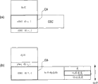
(a) when photo player 370 is connected to television receiver 250 via HDMI cable 391, (b) photo player 370 obtains physical address [1000] through using the HDMI control protocol from television receiver 250.
The device of deferring to CEC is defined as acquisition logical address when HDMI connects.Use logical address, defer to the device transmission/reception message of CEC.Figure 26 illustrates the CEC table, and this table illustrates the corresponding relation between device and the CEC logical address.
The device that is called " TV " is TV, projecting apparatus etc.The device that is called " tape deck " is a HDD register etc.The device that is called " tuner " is STB (STB) etc.The device that is called " playback reproducer " is DVD player, video camera etc.The device that is called " audio system " is an AV amplifier etc.
Visible from the table of Figure 26, the quantity of the self-contained unit that definition can connect at every turn.When the device that connected more than or equal to defined quantity, the logical address of these devices will be { 15}.
Return with reference to Figure 25, (c) because photo player 370 itself is a playback reproducer, { 4} is as the controlled playback reproducer of CEC so photo player 370 is decided logical address based on the voting of Figure 26.In this case; Identify not exist and have logical address { after other device of 4}, { 4} is as its logical address in photo player 370 decision logic addresses through using the CEC control protocol to carry out query messages (PollingMessage) in photo player 370.
(d) { after the 4}, photo player 370 is through using CEC control protocol reports on the implementation physical address, being the device { fact of 4} of deferring to CEC to television receiver 250 notice physical addresss [1000] in the decision logic address as stated in photo player 370.
(e) when dish register 210 is connected to television receiver 250 via HDMI cable 392, (f) dish register 210 obtains physical address [2000] through using the HDMI control protocol from television receiver 250.
(g) because dish register 210 itself is a tape deck, { 1} is as CEC controlled recording device so dish register 210 is confirmed logical address based on the table of Figure 26.In this case, identify not exist and have logical address { after other device of 1}, { 1} is as its logical address in dish register 210 decision logic addresses through using the CEC control protocol to carry out query messages at dish register 210.
(h) { after the 1}, dish register 210 is through using CEC control protocol reports on the implementation physical address, being the device { fact of 1} of deferring to CEC to television receiver 250 notice physical addresss [2000] in the decision logic address as stated at dish register 210.
Figure 27 is the example that illustrates the operating sequence when carrying out the playback controls of photo player 370 and dish register 210 through the remote-controlled transmitter 277 that uses television receiver 250.
(a) when the remote-controlled transmitter 277 of user through using television receiver 250 switches to photo player 370 with input, (b) television receiver 250 notifies to the device that is connected, defer to CEC and will import the fact that switches to photo player 370 from television receiver 250 through using the CEC control protocol to carry out SetStreamPath (flow path is set) [0000] → [1000].
(c) photo player 370 that has a logical address [1000] detects this notice, and { 4} → { F} comes to be switched to the device of device notice under CEC control that is connected, defer to CEC the fact of photo player 370 through carrying out ActiveSource (active source).(d) therefore, television receiver 250 sends the destination with remote control and switches to photo player 370.
(e) when the user presses the playback key on the remote-controlled transmitter 277 of television receiver 250, (f) television receiver 250 uses the CEC control protocols to the device notice UserControlPressed (pressing user's control) that is connected, defer to CEC: PB{4}.(g) { photo player 370 of 4} detects this notice, plays the image in the flash memory, and via HDMI cable 391 playback output is sent to television receiver 250 to have logical address.
Next; (h) when the user switches to dish register 210 through the remote-controlled transmitter 277 that uses television receiver 250 with input, (i) television receiver 250 will imports the fact that switches to dish register 210 from photo player 370 to the device notice that is connected, defer to CEC through using the CEC control protocol to carry out SetStreamPath [1000] → [2000].
(j) the dish register 210 that has a physical address [2000] detects this notice, and ActiveSource{1} → { F} comes to be switched to the fact of coiling register 210 to the device notice that is connected, defer to CEC at CEC control device down through carrying out.(k) therefore, television receiver 250 sends the destination with remote control and switches to dish register 210.
(m) when the user presses the playback key of remote-controlled transmitter 277 of television receiver 250, (n) television receiver 250 uses the CEC control protocols to the device notice UserControlPressed:PB{1} that is connected, defer to CEC.(p) { the dish register 210 of 1} detects this notice, plays the image at disc recording, and via HDMI cable 392 playback output is sent to television receiver 250 to have logical address.
Figure 28 illustrates the topology example of photo player 370.Photo player 370 comprises HDMI terminal 371, HDMI transmitting element 372, CPU (CPU) 374, ROM (read-only memory) 375, RAM (random access memory) 376, bus 377, external memory interface 378 and signal processing LSI 379.
In photo player 370, CPU 374, ROM 375 and RAM 376 are through bus 377 interconnection.The operation of each unit of CPU 374 control photo player 370.The operation sequence of ROM 375 storage CPU374 etc.RAM 375 is as the working region of CPU 374 grades.CPU 374 through from ROM read operation program and on RAM the extended operation program come executive control operation.
In addition, external memory interface 378 is connected to bus 377 with signal processing LSI 379.External memory interface 378 comprises the loading unit that is used for flash memory 380.Under the control of CPU 374, external memory interface 378 reads static image data from the flash memory 380 that is loaded.For example, external memory interface 378 is Storage Card Drivers devices, and flash memory 380 is storage cards.
As stated, the static image data that reads from flash memory 380 is compress coding data (such as a jpeg data).Signal processing LSI 379 is applied to the static image data that reads from flash memory 380 with extension process, and obtains baseband video signal (view data).HDMI transmitting element 372 sends the baseband video signal that is obtained by signal processing LSI through carrying out the communication based on HDMI from HDMI terminal 371.
Shown in the dotted line of Figure 29; In photo player shown in Figure 28 370; CEC line via HDMI cable 391 offers RAM 376 via CPU 374 from HDMI transmitting element 372 from the control command that television receiver 250 provides, and is kept at provisionally among the RAM 376.CPU 374 reads and analyzes the CEC control command that is kept among the RAM 376.
When the CEC control command is playback command, under the control of CPU 374, use external memory interface 378 to carry out the operation of reading static image data from the flash memory 380 that is loaded.Shown in the dotted line of Figure 30, the static image data that reads from flash memory 380 is provided to RAM 376 via bus 377 from external memory interface 378, and is kept at provisionally among the RAM 376.
Then, shown in the dotted line of Figure 30, from RAM 376, read in the static image data of preserving among the RAM 376, and it is offered signal processing LSI 379.Signal processing LSI 379 is applied to the static image data that provides from RAM 376 with extension process, and obtains baseband video signal (view data).Baseband video signal is offered HDMI transmitting element 372, and send it to the HDMI cable 391 that is connected with HDMI terminal 371.
As stated; Because the two all is devices of deferring to CEC for the dish register 210 in the AV system 200 shown in Figure 24 and photo player 370, therefore can use the remote-controlled transmitter 277 control panel registers 210 of television receiver 250 and the operation of photo player 370.
On the contrary, the 200A of AV system shown in Figure 31 also is possible.In Figure 31, will give identical Reference numeral with the corresponding part of Figure 24.In the 200A of AV system, replace the dish register 210 in the AV system 200 shown in Figure 24, dish register 210A is connected to television receiver 250 via HDMI cable 392.
Because in the 200A of AV system, photo player 370 is to defer to the device of CEC, therefore can use the operation of the remote-controlled transmitter 277 control photo player 370 of television receiver 250.Yet,, therefore can not use the operation of the remote-controlled transmitter 277 control panel register 210A of television receiver 250 because dish register 210A is a device of not deferring to CEC.
Therefore, through the infrared ray receiving element 231 that comprises among the use dish register 210A, the remote-controlled transmitter 232 of use dish register 210A is carried out the operation of the dish register 210A among the 200A of AV system.
Patent file 1: open No.WO2002/078336
Summary of the invention
Technical problem
As among the 200A of AV system of above-mentioned Figure 31, be connected to via the HDMI cable among each device of television receiver 250, can not carry out use the controling of remote-controlled transmitter 277 of television receiver 250 to the device of not deferring to CEC.Yet if can carry out use the controling of remote-controlled transmitter 277 of television receiver 250 to the device of not deferring to CEC, this is very easily.
Target of the present invention is: make that can control (for example) through the remote-controlled transmitter that uses television receiver is connected to device television receiver, that do not defer to CEC.
Technical scheme
One aspect of the present invention relates to a kind of electronic installation, comprising:
Information setting unit is used to be provided with the information of controlled device;
The control signal converting unit, the control signal that is used at first form is when being used for the control signal of controlled device, converts control signal the control signal of second form into, wherein said information setting unit is provided with information to said controlled device; With
The control signal transmitting element is used for the control signal of second form of control signal converting unit conversion is sent to controlled device.
In the present invention, by the information of information setting unit sets controlled device.For example, when the control signal of first form is the CEC signal, be set to the information of controlled device to the physical address and the device classification of major general's controlled device.Owing to be provided with the physical address and device classification of controlled device as stated, therefore, replace controlled device, can determine the CEC logical address virtually.
When the control signal of first form is when being used for the control signal of above-mentioned controlled device, control signal is converted into the control signal of second form by the control signal converting unit.For example, when the control signal of first form is the CEC signal, if the CEC logical address of the destination of indication CEC signal and the above-mentioned CEC logical address coupling that determines confirm that then the CEC signal is the control signal that is used for controlled device virtually.
For example, receive the control signal of first form from external device (ED) by the control signal receiving element.For example, externally in the device, the remote signal that is received based on the remote control receiving element by control signal generating unit produces the control signal of first form.
In the device that comprises vision signal transmitting element (through using a plurality of channels vision signal being sent to external device (ED) as differential signal via transmission path), the control signal receiving element can receive the control signal of first form via the control data line of forming transmission path from external device (ED).For example, the control signal of first form is the CEC signal, and the control signal of second form is an infrared signal.
In addition, for example, the remote signal that is received based on the remote control receiving element by control signal generating unit produces the control signal of first form.
The control signal controlled signal transmitting element of first form that is obtained by the control signal converting unit sends to controlled device.Via cable or wirelessly the control signal of second form is sent to controlled device as (for example) infrared signal.
In addition; For example; As stated; In the device that comprises vision signal transmitting element (it sends to external device (ED) with vision signal as differential signal through using a plurality of channels via transmission path), the control signal that the control signal transmitting element can send second form via the bi-directional communication channel of being made up of the predetermined line of transmission path.Predetermined line is reservation line and the HPD line that (for example) formed the HDMI cable.
In addition; For example; The device that comprises video reception unit (it receives vision signal as differential signal through using a plurality of channels from controlled device via transmission path), the control signal transmitting element can send to controlled device with the control signal of second form via the bi-directional communication channel of being made up of the predetermined line of transmission path.
In the present invention, as stated, when the control signal of first form is when being used for the control signal of controlled device, convert the control signal of first form control signal of second form into, and the control signal of second form is sent to controlled device.Can carry out the controling of controlled device of the control signal of only handling second form based on the control signal of first form.
In addition, one side of the present invention is a kind of electronic installation, comprising:
The address information receiving element is used for receiving from first external device (ED) of the control signal of handling first form address information of second external device (ED) of the control signal of handling second form;
The remote control receiving element is used to receive remote signal;
Control signal generating unit, the address information of second external device (ED) that remote signal that is used for receiving based on the remote control receiving element and address information receiving element receive produces the control signal of first form to second external device (ED); With
The control signal transmitting element is used for the control signal of first form that is produced by control signal generating unit is sent to first external device (ED).
In the present invention, receive the address information of second external device (ED) of the control signal of handling second form from first external device (ED) of the control signal of handling first form by the address information receiving element.The remote signal that receives based on the remote control receiving element and the above-mentioned address information of second external device (ED) produce the control signal to first form of second external device (ED) by control signal generating unit.The control signal of first form is sent to first external device (ED).
The device that comprises video reception unit (it receives vision signal as differential signal through using a plurality of channels from first external device (ED) via transmission path), the control signal transmitting element can send to first external device (ED) with the control signal of first form via the control data line of forming transmission path.For example; The control signal of first form is the CEC signal, and, as stated; The address information of second external device (ED) that is received by the address information receiving element is the virtual logical address of second external device (ED), and this virtual logical address is set in first external device (ED).
In first external device (ED), when the control signal of first form that receives is used for second external device (ED), is the control signal of second form with the conversion of signals of first form, and the control signal of second form is sent to second external device (ED).Therefore, in the present invention, the control signal of first form is sent to first external device (ED), and, through first external device (ED), can carry out the controling of second external device (ED) of the control signal of only handling second form.
Advantageous effect
According to the present invention, can carry out the controling of controlled device of the control signal of only handling second form based on the control signal of first form.For example, can use the remote-controlled transmitter control and television receiver (it is a device of deferring to CEC) operation that be connected, that do not defer to the device of CEC of television receiver.
Description of drawings
Fig. 1 is the block diagram of diagram as the topology example of the AV system of embodiments of the invention.
Fig. 2 be the diagram photo player (source device) of forming the AV system the block diagram of topology example.
Fig. 3 is the block diagram that illustrates the topology example of the dish register (source device) of forming the AV system;
Fig. 4 is the block diagram that illustrates the topology example of the television receiver (sink device) of forming the AV system;
Fig. 5 is the block diagram of the topology example of diagram HDMI transmitting element (HDMI information source) and HDMI receiving element (HDMI sink device).
Fig. 6 is the block diagram of the topology example of diagram HDMI conveyer and HDMI receiver.
Fig. 7 is the figure of the structure of diagram TMDS transmission data.
Fig. 8 is the figure of the pin arrangement (type A) of diagram HDMI terminal.
Fig. 9 is the connection layout of topology example of the high-speed data line interface of diagram source device and sink device.
Figure 10 is the figure that is shown in photo player and coils register the example of the operating sequence when being connected to television receiver.
Figure 11 is the figure of the example of the operating sequence when illustrating the playback controls of carrying out photo player and coiling register through the remote-controlled transmitter that uses television receiver.
Figure 12 is the figure of channel of playback controls of the dish register of the diagram remote-controlled transmitter that uses television receiver.
Figure 13 is the figure of the channel of the playback controls in the diagram photo player.
Figure 14 is the bi-directional communication channel that diagram is formed via the preset lines of HDMI cable, control signal is sent to the figure of the example of dish register from photo player.
Figure 15 is the block diagram of diagram as the topology example of the AV system of another embodiment of the present invention.
Figure 16 comprises the figure of the demonstration example the when user who is shown in the remote control of carrying out television receiver is provided with.
Figure 17 is the block diagram of diagram as the topology example of the AV system of another embodiment of the present invention.
Figure 18 is the figure that illustrates the topology example of the AV amplifier (transponder set) of forming the AV system.
Figure 19 is shown in the AV amplifier to be connected to television receiver, and the figure of photo player and the example of the operating sequence of dish register when being connected to the AV amplifier in addition.
Figure 20 is the figure of user that diagram is carried out the AV amplifier demonstration example when being provided with.
Figure 21 is the figure of the example of the operating sequence when being shown in the playback controls of carrying out photo player and coiling register through the remote-controlled transmitter that uses television receiver.
Figure 22 is the figure of channel of playback controls of the dish register of the diagram remote-controlled transmitter that uses television receiver.
Figure 23 is the bi-directional communication channel that diagram is formed via the preset lines of HDMI cable, control signal is sent to the figure of the example of dish register from the AV amplifier.
Figure 24 is the block diagram of the topology example of the known AV of diagram system.
Figure 25 is the figure that is shown in photo player and coils register the example of the operating sequence when being connected to television receiver.
Figure 26 is the figure of diagram CEC table, and this CEC table illustrates the corresponding relation between device and the CEC logical address.
Figure 27 is the figure of the example of the operating sequence when illustrating the playback controls of carrying out photo player and coiling register through the remote-controlled transmitter that uses television receiver.
Figure 28 is the block diagram of the topology example of diagram photo player.
Figure 29 is the figure that is used to be described in the operation of photo player when receiving the CEC control command.
Figure 30 is the figure that is used to be described in the operation of photo player when reading static image data.
Figure 31 is the block diagram of another topology example of the known AV of diagram system.
The explanation of Reference numeral
100,100 ', 100 ": the AV system; 210B: dish register; The 211:HDMI terminal; The 212:HDMI transmitting element; 213: the high-speed data line interface; 231: the infrared ray receiving element; 250B, 250B ': television receiver; 251,254:HDMI terminal; 252,255:HDMI receiving element; 253,256: the high-speed data line interface; 276: the infrared ray receiving element; 277: remote-controlled transmitter; 278: the infrared ray transmitting element; The 310:AV amplifier; 311A, 311B, 314:HDMI terminal; 330: the infrared ray transmitting element; 370B, 370B ': photo player; The 371:HDMI terminal; The 372:HDMI transmitting element; 373: the high-speed data line interface; 384: the infrared ray transmitting element; 391,392,393:HDMI cable.
Embodiment
Embodiments of the invention are described below with reference to accompanying drawings.Fig. 1 illustrates the topology example as the AV system 100 of embodiment.
In addition, dish register 210B and television receiver 250B interconnect via HDMI cable 392.In dish register 210B, the HDMI terminal 211 that is connected with high-speed data line interface 213 with HDMI transmitting element (HDMI TX) 212 is provided.In television receiver 250B, the HDMI terminal 254 that is connected with high-speed data line interface 256 with HDMI receiving element (HDMI RX) 255 is provided.One of two ends of HDMI cable 392 are connected to the HDMI terminal 211 of dish register 210B, and the other end of HDMI cable 392 is connected to the HDMI terminal 254 of television receiver 250B.
In AV system 100 shown in Figure 1, via HDMI cable 391 vision signal (view data) that photo player 370B plays is provided to television receiver 250B, and on television receiver 250B, shows replay image.In addition, in AV system 100 shown in Figure 1, the vision signal (view data) that will coil register 210B broadcast via HDMI cable 392 is provided to television receiver 250B, and on television receiver 250B, shows replay image.
Fig. 2 illustrates the topology example of photo player 370B.Photo player 370B comprises HDMI terminal 371, HDMI transmitting element 372, high-speed data line interface 373, CPU (CPU) 374, ROM (read-only memory) 375, RAM (random access memory) 376, bus 377, external interface 378, signal processing LSI 379, Ethernet interface (Ethernet I/F) 381, network terminal 382, infrared transmitter circuit 383 and infrared ray transmitting element 384.Notice that " Ethernet " is registered trade mark.
In photo player 370B, CPU 374, ROM 375 and RAM 376 are through bus 377 interconnection.The operation of each unit of CPU 374 control photo player 370B.The operation sequence of ROM 375 storage CPU374 etc.RAM 376 is as the working region of CPU 374 grades.CPU 374 through from ROM read operation program and on RAM the extended operation program come executive control operation.
In addition, external memory interface 378, signal processing LSI 379, Ethernet interface 381 and infrared transmitter circuit 383 are connected to bus 377.External memory interface 378 comprises the loading unit that is used for flash memory 380.Under the control of CPU 374, external memory interface 378 reads static image data from the flash memory 380 that is loaded.For example, external memory interface 378 is Storage Card Drivers devices, and flash memory 380 is storage cards.
As stated, the static image data that reads from flash memory 380 is the compress coding data such as jpeg data.Signal processing LSI 379 is applied to the static image data that reads from flash memory 380 with extension process, and obtains baseband video signal (view data).
Under the control of CPU 374, infrared transmitter circuit 383 drives infrared ray transmitting element 384 and produces infrared signal.Infrared ray transmitting element 384 is made up of (for example) infrared transmitting device.
HDMI transmitting element (HDMI information source) 372 sends baseband video signal (view data) through carrying out the communication based on HDMI from HDMI terminal 371.Will be discussed in more detail below HDMI transmitting element 372.High-speed data line interface 373 is bi-directional communication interface, and it uses the predetermined line (in this embodiment for keeping line and HPD line) of forming the HDMI cable.Will be discussed in more detail below high-speed data line interface 373.
High-speed data line interface 373 is connected to bus 377 via Ethernet interface 381.In addition, network terminal 382 is connected to Ethernet interface 381.
With the operation of briefly describing illustrated photo player 370B among Fig. 2.When playback writes the static image data in the flash memory 380, with carrying out following operation.Just, external memory interface 378 is carried out the operation of reading static image data from the flash memory 380 that is loaded.To be provided to RAM 376 from external memory interface 378 from the static image data that flash memory 380 reads via bus 377, and be kept at provisionally among the RAM 376.
From RAM 376 reading and saving static image data among RAMs 376, and it be provided to signal processing LSI 379 thereafter.Signal processing LSI379 is applied to the static image data that provides from RAM 376 with extension process, and obtains baseband video signal (view data).Baseband video signal is provided to HDMI transmitting element 372, and sends it to HDMI terminal 371.
When the static image data of in RAM 376, preserving sends to network, will carry out following operations.Just, external memory interface 378 is carried out the operation of reading static image data from the flash memory 380 that loads.Via bus 377, will be provided to RAM 376 from external memory interface 378 from the static image data that flash memory 380 reads, and it will be kept among the RAM 376 provisionally.
Thereafter; Read the static image data of preserving the RAM 376 from RAM 376; It is made as IP divides into groups, and it is outputed to network terminal 382 or through Ethernet interface 381 and high speed data lines 373 it is outputed to HDMI terminal 371 via Ethernet interface 381.
Fig. 3 illustrates the topology example of dish register 210B.Dish register 210B comprises HDMI terminal 211; HDMI transmitting element 212; High-speed data line interface 213; Antenna terminal 214; Digital tuner 215; Demultiplexer 216; Internal bus 217; Record cell interface 218; DVD/BD driver 219; HDD (hard disk drive) 220; CPU (CPU) 221; Flash ROM (read-only memory) 222; DRAM (dynamic random access memory) 223; Ethernet interface (Ethernet I/F) 224; Network terminal 225; DTCP (DTCP) circuit 226; Mpeg decoder 227; Graphics generation circuit 228; Video output terminal 229; Audio output 230 and infrared ray receiving element 231.
HDMI transmitting element (HDMI information source) 212 sends base band video and voice data through carrying out based on the communication of HDMI from HDMI terminal 211.Will be discussed in more detail below HDMI transmitting element 212.High-speed data line interface 213 is to use the bi-directional communication interface of the predetermined line (in the present embodiment for keeping line and HPD line) of forming the HDMI cable.Will be discussed in more detail below high-speed data line interface 213.
Antenna terminal 214 is terminals of importing the television broadcasting signal that receives at reception antenna (not shown) place to it.Digital tuner 215 is handled the television broadcasting signal that is input to antenna terminal 214, and the predetermined MPTS of output.Demultiplexer 216 extracts part TS (MPTS) (TS of video data divides into groups and the TS of voice data divides into groups) according to predetermined selected channel from the MPTS that digital tuner 215 obtains.
In addition, demultiplexer 216 extracts PSI/SI (PSI/SI) from the MPTS that digital tuner 215 obtains, and PSI/SI is outputed to CPU 221.Multiplexing a plurality of channels in the MPTS that digital tuner 215 obtains.Through from PSI/SI (PAT/PMT), obtaining the information of the packet ID (PID) of any channel, make and from MPTS, to extract the part TS of any channel through using demultiplexer 216.
CPU 221, flash ROM 222, DRAM 223, demultiplexer 216, Ethernet interface 224 and record cell interface 218 are connected to internal bus 217.DVD/BD driver 219 is connected to internal bus 217 with HDD 220 via record cell interface 218.DVD/BD driver 219 and the part TS of HDD record by demultiplexer 216 extractions.In addition, DVD/BD driver 219 and HDD 220 each all play the part TS that on recording medium, writes down.
Mpeg decoder 227 is carried out the decoding processing that video PES divides into groups, and obtains video data, and wherein video PES divides into groups to form part TS that is extracted by demultiplexer 216 or the part TS that is play by DVD/BD driver 219 or HDD 220.In addition, mpeg decoder 227 is carried out the decoding processing that the audio frequency PES of part TS divides into groups and is obtained voice data.
As required, graphics generation circuit 228 is carried out the be added to processing of the video data that mpeg decoder 227 obtains of graph data.Video output terminal 229 outputs are from the video data of graphics generation circuit 228 outputs.The voice data that 230 outputs of audio output are obtained by mpeg decoder 227.
As required, DTCP circuit 226 is encrypted by the part TS of demultiplexer 216 extractions or the part TS of DVD/BD driver 219 or HDD 220 broadcasts.In addition, DTCP circuit 226 will be deciphered from the enciphered data that network terminal 225 or high-speed data line interface 213 are provided to Ethernet interface 224.
The operation of each unit of CPU 221 control panel register 210B.Flash ROM 222 storage Control Software and file datas.DRAM 223 forms the working region of CPU 221.CPU 221 expands software and the data that read from flash ROM 222 on DRAM223, activating software, and each unit of control panel register 210B.
As the general was described hereinafter, infrared ray receiving element 231 received the infrared signal that sends from the infrared ray transmitting element 384 of photo player 370.
With the operation of simply describing the dish register 210B shown in Fig. 3.
The television broadcasting signal that is input to antenna terminal 214 is offered digital tuner 215.In digital tuner 215, handle television broadcasting signal and extract predetermined MPTS, and predetermined MPTS is offered demultiplexer 216.In demultiplexer 216, from MPTS, extract part TS (TS of video data divides into groups and the TS of voice data divides into groups) according to predetermined channel.Via record cell interface 218, part TS is offered DVD/BD driver 219 or HDD 220, and come recording section TS based on recording instruction from CPU 221.
In addition, as stated, the part TS of demultiplexer 216 extractions or the part TS of DVD/BD driver 219 or HDD 220 broadcasts are offered mpeg decoder 227.In mpeg decoder 227, carry out the decoding processing of the video PES grouping that the TS by video data forms, with the acquisition video data.For example, through using video to produce after circuit 228 carried out the processing of video data that graph data is added to, video data is outputed to video output terminal 229.In addition, in mpeg decoder 227, carry out the decoding processing of the audio frequency PES grouping that the TS by voice data forms, with the acquisition voice data.Voice data is outputed to audio output 230.
To offer HDMI transmitting element 212 by video (image) data and the voice data that mpeg decoder 227 obtains according to the part TS of DVD/BD driver 219 or HDD 220 broadcasts, and send it to the HDMI cable that is connected with HDMI terminal 211.
In addition, can the part TS of the part TS that is extracted by demultiplexer 216 or DVD/BD driver 219 or HDD 220 broadcasts be sent to network.In this case, after encrypting, part TS is outputed to network terminal 225 via Ethernet interface 224 by 226 couples of part TS of DTCP circuit.Alternatively, in this case, after encrypting, part TS is outputed to HDMI terminal 211 through Ethernet interface 224 and high-speed data line interface 213 by 226 couples of part TS of DTCP circuit.
Fig. 4 illustrates the topology example of television receiver 250B.Television receiver 250B comprises HDMI terminal 251 and 254; HDMI receiving element 252 and 255; High-speed data line interface 253 and 256; Antenna terminal 257; Digital tuner 258; Demultiplexer 259; MPEG (Motion Picture Experts Group) decoder 260; Video/graphics treatment circuit 261; Panel drive circuit 262; Display floater 263; Audio signal processing circuit 264; Audio amplifier circuit 265; Loud speaker 266; DTCP circuit 267; Internal bus 270; CPU 271; Flash ROM 272; DRAM 273; Ethernet interface (Ethernet I/F) 274; Network terminal 275; Infrared ray receiving element 276 and remote-controlled transmitter 277.
In addition, demultiplexer 259 extracts PSI/SI (PSI/SI) from the MPTS that digital tuner 258 obtains, and PSI/SI is outputed to CPI 271.Multiplexing a plurality of channels in the MPTS that digital tuner 258 obtains.Can carry out processing through from PSI/SI (PAT/PMT), obtaining the information of the packet ID (PID) of any channel, making through using demultiplexer 259 from MPTS, to extract the part TS of any channel.
As required, video/graphics treatment circuit 261 carries out that multi-screens are handled and with the be added to overlap-add procedure of the video data that mpeg decoder 260 obtains of graph data.Panel drive circuit 262 drives display floater 263 based on the video data from 261 outputs of video/graphics treatment circuit.Display floater 263 (for example) is made up of LCD (LCD) or PDP (plasma display panel).Audio signal processing circuit 264 is carried out necessity such as the D/A conversion of the voice data of mpeg decoder acquisition and is handled.Audio amplifier circuit 265 amplifies from the audio signal of audio signal processing circuit 264 outputs, and audio signal is offered loud speaker 266.
As required, DTCP circuit 267 is encrypted the part TS that is extracted by demultiplexer 259.In addition, DTCP circuit 267 will be deciphered from the enciphered data that network terminal 275 or high-speed data line interface 253 or 256 are provided to Ethernet interface 274.
The operation of each unit of CPU 271 control television receiver 250B.Flash ROM 272 storage Control Software and file datas.DRAM 273 forms the working region of CPU 271.CPU 271 expands software and the data that read from flash ROM 272 on DRAM 273, activating software, and each unit of control television receiver 250B.Infrared ray receiving element 276 receives the remote signal (remote control code) of sending from remote-controlled transmitter 277, and remote signal is offered CPU 271.CPU 271, flash ROM 272, DRAM 273 and Ethernet interface 274 are connected to internal bus 270.
HDMI receiving element (HDMI sink device) 252 receives the base band video (image) and the voice data that are provided to HDMI terminal 251 and 254 through carrying out based on communicating by letter of HDMI with 255.Will be discussed in more detail below HDMI receiving element 252 and 255.High-speed data line interface 253 and 256 is bi-directional communication interface, and it uses the predetermined line (in the present embodiment for keeping line and HPD line) of forming the HDMI cable.Will be discussed in more detail below high-speed data line interface 253 and 256.
With the operation of briefly describing television receiver 250B shown in Figure 4.
The television broadcasting signal that is input to antenna terminal 157 is offered digital tuner 258.In digital tuner 258,, handle television broadcasting signal and extract predetermined MPTS, and predetermined MPTS is offered demultiplexer 259 according to user-selected channel.In demultiplexer 259, from MPTS, extract part TS (TS of video data divides into groups and the TS of voice data divides into groups) according to user-selected channel.Part TS is offered mpeg decoder 260.
In mpeg decoder 260, the decoding processing of carrying out the video PES grouping that the TS by video data forms obtains video data.Afterwards, for example, if necessary, carry out in video/graphics treatment circuit 261 then that multi-screen is handled and, video data is provided to panel drive circuit 262 the be added to overlap-add procedure of video data of graph data.Therefore, the image that shows the channel of selecting according to the user at display floater 263.
In addition, in mpeg decoder 260, the decoding processing of carrying out the audio frequency PES grouping that the TS by voice data forms obtains voice data.In audio signal processing circuit 264, necessity that voice data is carried out such as the D/A conversion is handled.In addition, amplify voice data, then it is offered loud speaker 266 by audio amplifier circuit 265.Therefore, from the audio frequency of loud speaker 266 outputs according to the channel of user's selection.
When the reception of above-mentioned television broadcasting signal, can the part TS that demultiplexer 259 extracts be sent to network.In this case, after encrypting, part TS is outputed to network terminal 275 via Ethernet interface 274 by 267 couples of part TS of DTCP circuit.Alternatively, in this case, after DTCP circuit 267 has been encrypted part TS, part TS is outputed to HDMI terminal 251 or 254 through Ethernet interface 274 and high-speed data line interface 253 or 256.
Note,, part TS is provided to mpeg decoder 260 being provided to from network terminal 275 by 267 pairs in DTCP circuit after part TS Ethernet interface 274, encrypted deciphers.Alternatively, being provided to from HDMI terminal 251 or 254 via high-speed data line interface 253 or 256 by 267 pairs in DTCP circuit after part TS Ethernet interface 274, encrypted deciphers, part TS is provided to mpeg decoder 260.Carry out and the operation identical operations when receiving above-mentioned television broadcasting signal carried out thereafter.Display image on display floater 263, and from loud speaker 266 output audios.
In addition, in HDMI receiving element 252 and 255, obtain to be input to video (image) data and the voice data of HDMI terminal 251 and 254 through the HDMI cable.Video data and voice data are offered video treatment circuit 261 and audio signal processing circuit 264 respectively.Carry out and the operation identical operations when receiving above-mentioned television broadcasting signal carried out thereafter.Display image on display floater 263, and from loud speaker 266 output audios.
Fig. 5 illustrates the topology example of HDMI receiving element (HDMI sink device) of HDMI transmitting element (HDMI information source) and the sink device (television receiver 250B) of source device (photo player 370B or dish register 210B).
The HDMI transmitting element is through using a plurality of channels; (wherein partly (horizontal blanking section) and vertical blanking partly obtain this AP part through removing horizontal blanking from a vertical synchronizing signal to the part of next vertical synchronizing signal) will send to the HDMI receiving element with the corresponding differential signal of pixel data of non-compressed image (equaling a screen) on the direction in AP part (below can also be called the motion video part).Simultaneously; The HDMI transmitting element is through using a plurality of channels; On the direction in horizontal blanking part or vertical blanking part, the differential signal corresponding with other auxiliary data of voice data, control data and accompanying image to the major general sends to the HDMI receiving element.
Just, the HDMI transmitting element comprises conveyer 81.Conveyer 81 will (for example) non-compressed image pixel data convert corresponding differential signal into, and through using three TMDS channel # 0, #1, #2 (a plurality of channel) to implement the serial transmission of the differential signal of HDMI receiving element (it is connected to conveyer 81 via the HDMI cable) in one direction.
In addition; Conveyer 81 with voice data and in addition necessary control data, other auxiliary data etc. of following incompressible view data convert differential signal into, and through using three TMDS channel # 0, #1, #2 to implement the serial transmission of the differential signal of HMDI receiving element (it is connected to conveyer 81 via the HDMI cable) in one direction.
In addition, conveyer 81 is through using TMDS clock channel, will with to send to HMDI receiving element (it is connected to conveyer 81 via the HDMI cable) through the synchronous pixel clock of pixel data that uses three TMDS channel # 0, #1 and #2 to send.Here, through using a TMDS channel #i (i=0,1,2) in a pixel clock, to send 10 pixel datas.
The HDMI receiving element receives the differential signal corresponding with pixel data, wherein through using a plurality of channels, on the direction in the motion video part, sends this differential signal from the HDMI transmitting element.Simultaneously, the differential signal that the reception of HDMI receiving element is corresponding with voice data and control data wherein through using a plurality of channels, on the direction in horizontal blanking part or vertical blanking part, sends this differential signal from the HDMI transmitting element.
Just, the HDMI receiving element comprises receiver 82.Receiver 82 with synchronously receive through the pixel clock that uses TMDS clock channel to send from the HDMI transmitting element equally with the corresponding differential signal of pixel data and with voice data and the corresponding differential signal of control data; Wherein, send these differential signals from the HDMI transmitting element that is connected with the HDMI receiving element via the HDMI cable through using TMDS channel # 0, #1, #2.
Act on a direction except using from the HDMI transmitting element to the HDMI receiving element; With pixel clock synchronously three TDMS channel # 0 of the transmission channel of serial transfer pixel data and voice data outside #2 and TMDS clock channel, comprise that the transmission channel of the HDMI system of HDMI transmitting element and HDMI receiving element also comprises the transmission channel that is called DDC (display data channel) 83 and CEC line 84 with the transmission channel that acts on the transmission pixel clock.
DDC 83 comprises the two signal line (not shown) that comprise in the HDMI cable.DDC 83 is used for the HDMI transmitting element to read E-EDID (strengthening the extending display identification data) via the HDMI cable from HDMI receiving element (being connected with the HDMI transmitting element).
Just, except HDMI receiver 82, the HDMI receiving element also comprises EDID ROM (read-only memory) 85, and its storage conduct is about the E-EDID of the performance information of its performance (configuration/ability).The HDMI transmitting element reads the E-EDID of HDMI receiving element from the HDMI receiving element that is connected with the HDMI transmitting element via the HDMI cable via DDC 83; And discern the pairing picture format of electronic installation (profile (profile)) that (for example) comprises the HDMI receiving element based on E-EDID, like RBG, YCbCr4:4:4 or YCbCr4:2:2 etc.
CEC line 84 comprises a signal line (not shown) that comprises in the HDMI cable.CEC line 84 is used between HDMI transmitting element and HDMI receiving element, carrying out the two-way communication of control data.
In addition, the line 86 that is connected to the pin (pin) that is called HPD (hot plug detection) is included in the HDMI cable.Source device can detect the connection of sink device through using line 86.In addition, be used for being included in the HDMI cable to the line 87 of sink device power supply from source device.In addition, keeping line 88 is included in the HDMI cable.
Fig. 6 illustrates the HDMI conveyer 81 of Fig. 5 and the topology example of HDMI receiver 82.
Conveyer 81 comprises respectively and three three encoders/serializer 81A, 81B and 81C that TMDS channel # 0, #1 and #2 are corresponding.Among encoder/serializer 81A, 81B and the 81C each is all encoded to the view data, auxiliary data and the control data that offer it, converts parallel data into serial data, and sends serial data according to differential signal.Here, when view data comprises three components R (red), G (green) and B (indigo plant), the B component is provided to encoder/serializer 81A; The G component is provided to encoder/serializer 81B; And the R component is provided to encoder/serializer 81C.
In addition, auxiliary data comprises (for example) voice data and control grouping.To control and divide into groups to offer (for example) encoder/serializer 81A, and voice data will be provided to encoder/serializer 81B and 81C.
In addition, control data comprises 1 vertical synchronizing signal (VSYNC), 1 horizontal-drive signal (HSYNC) and 1 control bit CTL0, CTL1, CTL2 and CTL3.Vertical synchronizing signal and horizontal-drive signal are provided to encoder/serializer 81A.Control bit CTL0 and CTL1 are provided to encoder/serializer 81B.Control bit CTL2 and CTL3 are provided to encoder/serializer 81C.
Encoder/serializer 81A sends B component, vertical synchronizing signal, horizontal-drive signal and the auxiliary data of the view data that offers it with time division way.Just, encoder/serializer 81A converts parallel data into the B component that 8 increment (fixedly figure place) will offer its view data.In addition, encoder/serializer 81A parallel data of encoding converts parallel data into serial data, and through using TMDS channel # 0 to send serial data.
In addition, encoder/serializer 81A encodes to comprising the vertical synchronizing signal that offers it and 2 parallel-by-bit data of horizontal-drive signal, converts parallel data into serial data, and through using TMDS channel # 0 to send serial data.In addition, encoder/serializer 81A converts parallel data into the auxiliary data that 4 increment will offer it.Encoder/serializer 81A parallel data of encoding converts parallel data into serial data, and through using TMDS channel # 0 to send serial data.
Encoder/serializer 81B sends G component, control bit CTL0 and the CTL1 and the auxiliary data of the view data that offers it with time division way.Just, encoder/serializer 81B converts parallel data into the G component that 8 increment (fixedly figure place) will offer its view data.In addition, encoder/serializer 81B parallel data of encoding converts parallel data into serial data, and through using TMDS channel # 1 to send serial data.
In addition, encoder/serializer 81B encodes to comprising the CTL0 that offers it and the 2 parallel-by-bit data of CTL1, converts parallel data into serial data, and through using TMDS channel # 1 to send serial data.In addition, encoder/serializer 81B converts parallel data into the auxiliary data that 4 increment will offer it.Encoder/serializer 81B parallel data of encoding converts parallel data into serial data, and through using TMDS channel # 1 to send serial data.
Encoder/serializer 81C sends R component, control bit CTL2 and the CTL3 and the auxiliary data of the view data that offers it with time division way.Just, encoder/serializer 81C converts parallel data into the R component that 8 increment (fixedly figure place) will offer its view data.In addition, encoder/serializer 81C parallel data of encoding converts parallel data into serial data, and through using TMDS channel # 2 to send serial data.
In addition, encoder/serializer 81C encodes to comprising the CTL2 that offers it and the 2 parallel-by-bit data of CTL3, converts parallel data into serial data, and through using TMDS channel # 2 to send serial data.In addition, encoder/serializer 81C converts parallel data into the auxiliary data that 4 increment will offer it.Encoder/serializer 81C parallel data of encoding converts parallel data into serial data, and through using TMDS channel # 2 to send serial data.
Receiver 82 comprises respectively and three three recovery/decoder 82A, 82B and 82C that TMDS channel # 0, #1 and #2 are corresponding.Recovery/decoder 82A, 82B and 82C receive view data, auxiliary data and the control data that sends according to differential signal individually through using TMDS channel # 0, #1 and #2.In addition, recovery/decoder 82A, 82B and 82C convert view data, auxiliary data and control data into parallel data from serial data individually, and decoding parallel data and output are through the data of decoding.
Just, recovery/decoder 82A receives through using TMDS channel # 0 to send to B component, vertical synchronizing signal, horizontal-drive signal and the auxiliary data of the view data of recovery/decoder 82A according to differential signal.Recovery/decoder 82A converts B component, vertical synchronizing signal, horizontal-drive signal and the auxiliary data of view data into parallel data from serial data, the decoding parallel data, and output is through the data of decoding.
Recovery/decoder 82B receives through using TMDS channel # 1 to send to G component, control bit CTL0 and the CTL1 and the auxiliary data of the view data of recovery/decoder 82B according to differential signal.Recovery/decoder 82B converts G component, control bit CTL0 and CTL1 and the auxiliary data of view data into parallel data from serial data, the decoding parallel data, and output is through the data of decoding.
Recovery/decoder 82C receives through using TMDS channel # 2 to send to R component, control bit CTL2 and the CTL3 and the auxiliary data of the view data of recovery/decoder 82C according to differential signal.Recovery/decoder 82C converts R component, control bit CTL2 and CTL3 and the auxiliary data of view data into parallel data from serial data, the decoding parallel data, and output is through the data of decoding.
Fig. 7 illustrates the hop example of (time period), wherein transmits each that transmits data through three TMDS channel # 0, #1 and the #2 that uses HDMI.Notice that Fig. 7 illustrates through using TMDS channel # 0, #1 and #2 to transmit each of transmission data under the situation of the progressive image (progressive image) with 720 * 480 pixels (level * vertical).
Transmitting in the video field (video field) of transmission data through three TMDS channel # 0, #1 and the #2 that uses HDMI; According to the transmission type of data; There is three types part, comprises: video data part (video data time period), data islands part (data island section) (data islands time period) and control section (control time section).
Here, video field partly is that rising edge (movable along) from specific vertical synchronizing signal is to the part of the rising edge of next vertical synchronizing signal.Video field part can be divided into horizontal blanking time section (horizontal blanking), vertical blanking time section (vertical blanking) and as the motion video through partly removing the part that horizontal blanking time section and vertical blanking time section obtain from video field partly (Active Video).
Video data partly is assigned to the motion video part.In video data part, transmit the data of the valid pixel (active pixel) of 720 pixels * 480 lines that equal to form non-compressing image data (equaling a screen).
Data islands part and control section are distributed to horizontal blanking time section and vertical blanking time section.In data islands part and control section, transmit auxiliary data.
Just, data islands is partly distributed to horizontal blanking time section and vertical blanking time section.In the data islands part, the voice data of the data that (for example) conduct among each of transmission auxiliary data and control are irrelevant.
Control section is distributed to the remainder of horizontal blanking time section and vertical blanking time section.In control section, (for example), the vertical synchronizing signal among each of transmission auxiliary data, horizontal-drive signal and control grouping (data item relevant) with control.
Here, in current HDMI, be (for example) 165MHz through the frequency of using the pixel clock that TMDS clock channel transmits.In this case, the transfer rate in the data islands part is about 500Mbps.
Fig. 8 illustrates the pin arrangement of HDMI terminal.Pin arrangement is the example of type A (type-A).
Two lines are connected to the pin that has distributed TMDS data #i+, and (the pin number is 1; 4; 7 pin) and the pin (the pin number is 3,6,9 pin) that has distributed TMDS data #i-; Wherein these two lines are differential lines, transmit TMDS data #i+ and TMDS data #i-as the differential signal of TMDS channel #i through this differential lines.
In addition, transmitting CEC line 84 as the CEC signal of control data through it, to be connected to the pin number be 13 pin.The pin number is that 14 pin is empty (reservation) pin.In addition, being connected to the pin number through its line that transmits SDA (serial data) signal such as E-EDID is 16 pin.Being connected to the pin number through its line that transmits SCL (serial clock) signal (synchronous as being used for when transmissions/receptions SDA signal realization) is 15 pin.Above-mentioned DDC 83 is made up of the line of line that transmits the SDA signal and transmission SCL signal.
In addition, as stated, being used for line 86 that source device detects the connection of sink device, to be connected to the pin number be 19 pin.In addition, as stated, it is 18 pin that the line 87 that is used to supply power is connected to the pin number.
Fig. 9 illustrates the topology example of the high-speed data line interface of source device and sink device.The high speed data lines interface is formed the communication unit of carrying out LAN (local area network (LAN)) communication.Communication unit is through using by a pair of differential lines in the many lines forming the HDMI cable (just corresponding with empty (reservation) pin (14 pin) in the present embodiment reservation line and the bi-directional communication channel executive communication of forming with the corresponding HPD line (Ether+line) of HPD pin (19 pin).
Source device comprises lan signal transtation mission circuit 411, terminating resistor 412, AC coupling capacitor 413 and 414, lan signal receiving circuit 415, subtraction circuit 416, pullup resistor (pull-up resistor) 421, the resistor 422 of forming low pass filter and capacitor 423, comparator 424, pull-down-resistor 431, forms resistance 432 and the capacitor 433 and the comparator 434 of low pass filter.Here, high-speed data line interface (high speed data lines I/F) is made up of lan signal transtation mission circuit 411, terminating resistor 412, AC coupling capacitor 413 and 414, lan signal receiving circuit 415 and subtraction circuit 416.
The series circuit that comprises pullup resistor 421, AC coupling capacitor 413, terminating resistor 412, AC coupling capacitor 414 and pull-down-resistor 431 be connected power line (+5.0V) and between the ground wire.Node P1 between AC coupling capacitor 413 and the terminating resistor 412 is connected to the positive output side of lan signal transtation mission circuit 411 and the positive input side of lan signal receiving circuit 415.In addition, the node P2 between AC coupling capacitor 414 and the terminating resistor 412 is connected to the negative output side of lan signal transtation mission circuit 411 and the negative input side of lan signal receiving circuit 415.To send signal (transmission data) SG411 and be provided to the input side of lan signal transtation mission circuit 411.
In addition, the output signal SG412 of lan signal receiving circuit 415 is provided to the positive side terminal of subtraction circuit 416.To send the minus side terminal that signal (transmission data) SG411 is provided to subtraction circuit 416.In subtraction circuit 416, deduct from the output signal SG412 of lan signal receiving circuit 415 and to send signal SG411, obtain to receive signal (reception data) SG413 thus.
In addition, the node Q1 between pullup resistor 421 and the AC coupling capacitor 413 is connected to ground wire via the series circuit that comprises resistor 422 and capacitor 423.The output signal of the low pass filter that will obtain at the node place between resistor 422 and the capacitor 423 is provided to one of two inputs of comparator 424.In comparator 424, with the output signal of low pass filter and the reference voltage Vref 1 that is provided to another input (+3.75V) compare.The output signal SG414 of comparator 424 is provided to the control unit (CPU) of source device.
In addition, the node Q2 between AC coupling capacitor 414 and the pull-down-resistor 431 is connected to ground wire via the series circuit that comprises resistor 432 and capacitor 433.The output signal of the low pass filter that will obtain at the node place between resistor 432 and the capacitor 433 is provided to one of two inputs of comparator 434.In comparator 434, with the output signal of low pass filter and the reference voltage Vref 2 that is provided to another input (+1.4V) compare.The output signal SG415 of comparator 434 is provided to the control unit (CPU) of source device.
Sink device comprises lan signal transtation mission circuit 411, terminating resistor 442, AC coupling capacitor 443 and 444, lan signal receiving circuit 445, subtraction circuit 446, pull-down-resistor 451, forms resistor 452 and capacitor 453, comparator 454, choke 461, resistor 462 and the resistor 463 of low pass filter.Here, high-speed data line interface (high speed data lines I/F) is made up of lan signal transtation mission circuit 441, terminating resistor 442, AC coupling capacitor 443 and 444, lan signal receiving circuit 445 and subtraction circuit 446.
The series circuit that comprises resistor 462 and resistor 463 be connected power line (+5.0V) and between the ground wire.The series circuit that comprises choke 461, AC coupling capacitor 444, terminating resistor 442, AC coupling capacitor 443 and pull-down-resistor 451 is connected between the node and ground wire between resistor 472 and the resistor 463.
Node P3 between AC coupling capacitor 443 and terminating resistor 442 is connected to the positive output side of lan signal transtation mission circuit 441 and the positive input side of lan signal receiving circuit 445.In addition, the node P4 between AC coupling capacitor 444 and terminating resistor 442 is connected to the negative output side of lan signal transtation mission circuit 441 and the negative input side of lan signal receiving circuit 445.To send signal (transmission data) SG417 and be provided to the input side of lan signal transtation mission circuit 441.
In addition, the output signal SG418 of lan signal receiving circuit 445 is provided to the positive side terminal of subtraction circuit 446.With sending the minus side terminal that signal SG417 is provided to subtraction circuit 446.In subtraction circuit 446, from the output signal SG418 of LAN letter receiving circuit 445, deduct and send signal SG417, obtain to receive signal (reception data) SG419 thus.
In addition, the node Q3 between pull-down-resistor 451 and AC coupling capacitor 443 is connected to ground wire via the series circuit that comprises resistor 452 and capacitor 453.The output signal of the low pass filter that will obtain at the node place between resistor 452 and the capacitor 453 is provided to one of two inputs of comparator 454.In comparator 454, with the output signal of low pass filter and the reference voltage Vref 3 that is provided to another input (+1.25V) compare.The output signal SG416 of comparator 454 is provided to the control unit (CPU) of sink device.
The reservation line 501 that is included in the HDMI cable is right with HPD line 502 composition differential twisted pairs.The information source side 511 that keeps line 501 is connected to 14 pins of the HDMI terminal of source device.The stay of two nights side 521 that keeps line 501 is connected to 14 pins of the HDMI terminal of sink device.In addition, the information source side 512 of HPD line 502 is connected to 19 pins of the HDMI terminal of source device.The stay of two nights side 522 of HPD line 502 is connected to 19 pins of the HDMI terminal of sink device.
In source device, the above-mentioned node Q1 between pullup resistor 421 and the AC coupling capacitor 413 is connected to 14 pins of HDMI terminal, and the above-mentioned node Q2 between pull-down-resistor 431 and the AC coupling capacitor 414 is connected to 19 pins of HDMI terminal.On the contrary, in sink device, the above-mentioned node Q3 between pull-down-resistor 451 and the AC coupling capacitor 433 is connected to 14 pins of HDMI terminal, and the above-mentioned node Q4 between choke 461 and the AC coupling capacitor 444 is connected to 19 pins of HDMI terminal.
Next, with describing through using the operation of the LAN communication of the high-speed data line interface of structure as stated.
In source device, will send signal (transmission data) SG411 and be provided to the input side of lan signal transtation mission circuit 411, and from 411 outputs of lan signal transtation mission circuit and the corresponding differential signal (positive output signal and negative output signal) of transmission signal SG411.To be provided to node P1 and P2 from the differential signal of lan signal transtation mission circuit 411 outputs, and send to sink device through a pair of line (keeping line 501 and HPD line 502) of HDMI cable.
In addition, in sink device, will send signal (transmission data) SG417 and be provided to the input side of lan signal transtation mission circuit 441, and from 441 outputs of lan signal transtation mission circuit and the corresponding differential signal (positive output signal and negative output signal) of transmission signal SG417.To be provided to node P3 and P4 from the differential signal of lan signal transtation mission circuit 441 outputs, and send to source device through a pair of line (keeping line 501 and HPD line 502) of HDMI cable.
In addition; In source device; Because the input side of lan signal receiving circuit 415 is connected to node P1 and P2, therefore obtain to be used as the output signal SG412 of lan signal receiving circuit 415 from the pairing transmission signal of differential signal (current demand signal) of lan signal transtation mission circuit 411 outputs and the sum signal of the pairing reception signal of differential signal that sends from aforesaid sink device.In subtraction circuit 416, from the output signal SG412 of lan signal receiving circuit 415, deduct and send signal SG411.Therefore, the output signal SG413 of subtraction circuit 416 is corresponding to transmission signal (transmission data) SG417 of sink device.
In addition; In sink device; Because the input side of lan signal receiving circuit 445 is connected to node P3 and P4, therefore obtain to be used as the output signal SG418 of lan signal receiving circuit 445 from the pairing transmission signal of differential signal (current demand signal) of lan signal transtation mission circuit 441 outputs and the sum signal of the pairing reception signal of differential signal that sends from sink device as stated.In subtraction circuit 446, from the output signal SG418 of lan signal receiving circuit 445, deduct and send signal SG417.Therefore, the output signal SG419 of subtraction circuit 416 is corresponding to transmission signal (transmission data) SG411 of source device.
As stated, can between the high-speed data line interface of the high-speed data line interface of source device and sink device, carry out two-way LAN communicates by letter.
Notice that in Fig. 9, except above-mentioned LAN communication, HPD line 502 utilizes the DC bias level, transmits the fact that the HDMI cable is connected to sink device to source device.Just, when the HDMI cable is connected to sink device, the resistor 462 in sink device and 463 and choke 461 via 19 pins of HDMI cable HPD line 502 is biased to about 4V.Source device comprises that through use the low pass filter of resistor 432 and capacitor 433 extracts the DC bias voltage of HPD line 502, and through use comparator 434 with DC bias voltage and reference voltage Vref 2 (as, 1.4V) compare.
When the HDMI cable is not connected to sink device, owing to have pull-down-resistor 431, so the voltage of 19 pins of the HDMI terminal of source device is lower than reference voltage Vref 2.On the contrary, when the HDMI cable was connected to sink device, the voltage of 19 pins of the HDMI terminal of source device was higher than reference voltage Vref 2.Therefore, when the HDMI cable was connected to sink device, the output signal SG415 of comparator 434 was in high level; Otherwise the output signal SG415 of comparator 434 is in low level.Therefore, whether the control unit of source device (CPU) can be connected to sink device based on the output signal SG415 identification HDMI cable of comparator 434.
In addition; In Fig. 9, comprised such function: device that its DC bias voltage that utilize to keep line 501 is discerned the two ends that are connected to the HDMI cable each other is can carry out LAN communicating devices (below be called " device of deferring to e-HDMI ") still can not carry out LAN communicating devices (below be called " device of not deferring to e-HDMI ").
As stated, source device draw through using on the resistor 421 (+5V) keep line 501, and sink device is through using resistor 451 drop-down reservation lines 501.In the device of not deferring to e-HDMI, there are not resistor 421 and 451.
As stated, source device compares the DC electromotive force and the reference voltage Vref 1 of passing through the reservation line 501 of the low pass filter that comprises resistor 422 and capacitor 423 through using comparator 424.When sink device is when deferring to the device of e-HDMI and comprising pull-down-resistor 451, the voltage that keeps line 501 becomes 2.5V.Yet when sink device is when not deferring to the device of e-HDMI and not comprising pull-down-resistor 451, owing to there is pullup resistor 421, the voltage that therefore keeps line 501 becomes 5V.
Therefore, if reference voltage Vref 1 is (for example) 3.75V, then when sink device be when deferring to the device of e-HDMI, the output signal SG414 of comparator 424 is in low level, otherwise is in high level.Therefore, whether the control unit of source device (CPU) can be the device of deferring to e-HDMI based on the output signal SG414 identification sink device of comparator 424.
Similarly, as stated, sink device compares the DC electromotive force and the reference voltage Vref 3 of passing through the reservation line 501 of the low pass filter that comprises resistor 452 and capacitor 453 through using comparator 454.When source device is to defer to the device of e-HDMI, and when comprising pullup resistor 421, the voltage that keeps line 501 becomes 2.5V.Yet when source device is not defer to the device of e-HDMI, and when not comprising pullup resistor 421, owing to there is pull-down-resistor 451, the voltage that therefore keeps line 501 becomes 0V.
Therefore, if reference voltage Vref 3 is (for example) 1.25V, then when source device be when deferring to the device of e-HDMI, the output signal SG416 of comparator 454 is in high level, otherwise is in low level.Therefore, whether the control unit of sink device (CPU) can be the device of deferring to e-HDMI based on the output signal SG416 identification source device of comparator 454.
According to topology example shown in Figure 9; HDMI cable is carried out the transmission of video and voice data through using, the exchange of the information of the device that is connected and checking, device control data communicate by letter with interface that LAN communicates by letter in; Via a pair of differential transmission path; Utilize two-way communication to carry out LAN communication, and the connection status of coming reporting interface through the DC bias potential of using at least one transmission path.Therefore, scl line or the sda line apart that physically is not used for LAN communication becomes possibility therein.As a result, can be independent of the circuit that is formed for LAN communication to the electrical code of DDC definition, and can communicate by letter with the stable and reliable LAN of implemented with low cost.
Notice that pullup resistor 421 shown in Figure 9 can be provided in the HDMI cable, rather than in source device.Under these circumstances, the terminal of pullup resistor 421 is connected respectively to reservation line 501 among the line that is provided with in the HDMI cable and the line (holding wire) that is connected with power supply (electrical source voltage).
In addition, pull-down-resistor 451 shown in Figure 9 can be provided in the HDMI cable with resistor 463, rather than in sink device.Under these circumstances, the terminal of pull-down-resistor 451 is connected respectively to reservation line 501 among the line that provides in the HDMI cable and the line (ground wire) that is connected with ground (reference potential).In addition, the terminal of resistor 463 is connected respectively to HPD line 502 among the line that provides in the HDMI cable and the line (ground wire) that is connected with ground (reference potential).
Figure 10 illustrates the example of the operating sequence when photo player 370B is connected to television receiver 250B with dish register 210B.
(a) when photo player 370B is connected to television receiver 250B via HDMI cable 391, (b) photo player 370B obtains physical address [1000] through using the HDMI control protocol from television receiver 250B.
(c) because photo player 370B itself is a playback reproducer, so photo player 370B decides logical address based on the voting of Figure 26, and { 4} is as the controlled playback reproducer of CEC.In this case, identify not exist and have logical address { after other device of 4}, { 4} is as its logical address in photo player 370B decision logic address through using the CEC control protocol to carry out query messages at photo player 370B.
(d) { after the 4}, photo player 370B is through using CEC control protocol reports on the implementation physical address, being the device { fact of 4} of deferring to CEC to television receiver 250B notice physical address [1000] in the decision logic address as stated at photo player 370B.
(e) when dish register 210B is connected to television receiver 250B via HDMI cable 392, (f) dish register 210B obtains physical address [2000] through using the HDMI control protocol from television receiver 250B.Here, because dish register 210B is a device of not deferring to CEC, therefore coils register 210B and do not carry out CEC logical address decision operation.
By user the fact that physical address [2000] be photo player 370B alternative physical address [2000] device (tape deck) controlled among photo player 370Bs be set (g) thereafter.The user can carry out this setting through the user operation unit 374A that uses (for example) to be connected to CPU 374.(h) according to above-mentioned setting, photo player 370B decides logical address based on the voting of Figure 26, and { 1} is as the controlled tape deck of CEC.In this case, identify not exist and have logical address { after other device of 1}, { 1} is as logical address in photo player 370B decision logic address through using the CEC control protocol to carry out query messages at photo player 370B.
(i) as stated; { after the 1}, photo player 370B is the device { fact of 1} of deferring to CEC through using CEC control protocol reports on the implementation physical address to notify television receiver 250B physical address [2000] in the photo player 370B decision logical address corresponding with physical address [2000].
The example of the operating sequence when Figure 11 illustrates the playback controls of carrying out photo player 370B and coiling register 210B through the remote-controlled transmitter 277 that uses television receiver 250B.
(a) when the user switches to photo player 370B through the remote-controlled transmitter 277 that uses television receiver 250B with input, (b) television receiver 250B comes will import the fact that switches to photo player 370B from television receiver 250B to the device notice that is connected, defer to CEC through using the CEC control protocol to carry out " SetStreamPath (flow path is set) [0000] → [1000] ".
(c) the photo player 370B that has a logical address [1000] detects this notice, and { 4} → { F} comes to be switched to the device of device notice under CEC control that is connected, defer to CEC the fact of photo player 370B through carrying out ActiveSource (active source).(d) therefore, television receiver 250B sends the destination with remote control and switches to photo player 370B.
(e) when the user presses the playback key on the remote-controlled transmitter 277 of television receiver 250B, (f) television receiver 250B uses the CEC control protocol to the device notice UserControlPressed (pressing user's control) that is connected, defer to CEC: PB{4}.(g) { the photo player 370B of 4} detects this notice, plays the image in flash memory, and via HDMI cable 391 playback output is sent to television receiver 250B to have logical address.Therefore, the replay image that on television receiver 250B, shows flash memory.
Next; (h) when the user switches to dish register 210B through the remote-controlled transmitter 277 that uses television receiver 250B with input, (i) television receiver 250B comes will import the fact that switches to dish register 210B from photo player 370B to the device notice that is connected, defer to CEC through using the CEC control protocol to carry out SetStreamPath [1000] → [2000].
(j) owing to carry out control,, photo player 370B should notify so detecting to physical address [2000] by photo player 370B replacement dish register 210B.ActiveSource{1} → { F} controls the fact that switches to dish register 210B with CEC to the device notice that is connected, defer to CEC to photo player 370B virtually through carrying out.(k) therefore, television receiver 250B sends the destination with remote control and switches to dish register 210B.
(m) when the user presses the playback key on the remote-controlled transmitter 277 of television receiver 250B, (n) television receiver 250B (CPU 271) uses the CEC control protocol to the device notice UserControlPressed:PB{1} that is connected, defer to CEC.Here, CPU 271 forms control signal generating unit.(p) because { control of 1} should be notified so photo player 370B detects to logical address by photo player 370B replacement dish register 210B execution.Photo player 370B converts the CEC playback command into the infra-red remote control order, and sends the infra-red remote control order through infrared radiation, and notice is not deferred to the dish register 210B of CEC thus.Carrying out through (for example) CPU 374 should conversion.In this case, CPU 374 forms the control signal converting unit.
(q) dish register 210B detects and should notify, and plays and is recorded in the image on the dish, and via HDMI cable 392 playback output is sent to television receiver 250B.Therefore, the replay image of display panel on television receiver 250B.
Figure 12 (through making with dashed lines) illustrates the channel of playback controls remote-controlled transmitter 277, above-mentioned dish register 210B of using television receiver 250B.Figure 13 (through making with dashed lines) illustrates the channel of the playback controls of photo player 370B.To be provided to RAM376 from HDMI transmitting element 372 from the CEC playback command (UserControlPressed:PB{1}) that television receiver 250B sends via CPU 374, and be kept at provisionally among the RAM 376.
As stated; In AV system 100 shown in Figure 1; When remote-controlled transmitter 277 operations of user through using television receiver 250B during, produce the CEC control command that is addressed to dish register 210B from television receiver 250B as the dish register 210B of the device of not deferring to CEC.In photo player 370B, convert the CEC control command into the infra-red remote control order, and the infra-red remote control order is sent to dish register 210B.Therefore, in AV system 100 shown in Figure 1, can be connected to the operation of the dish register 210B of device television receiver 250B, that do not defer to CEC through the remote-controlled transmitter 277 control conducts of using television receiver 250B.
Note, in the embodiment shown in fig. 1, illustrate the CEC control command that is addressed to dish register 210B is converted into the infra-red remote control order and the infra-red remote control order sent to the photo player 370B of dish register 210B.Yet; Photo player 370B can convert the CEC control command into the control signal of predetermined format, and can control signal be sent to dish register 210B via bi-directional communication channel shown in Figure 14, that be made up of the reservation line and the HPD line of HDMI cable 391 and 392.In this case, in photo player 370B, infrared transmitter circuit 383 becomes unnecessary with infrared ray transmitting element 384.In addition, in this case, in dish register 210B, it is unnecessary that infrared ray receiving element 231 also becomes.
Next, another embodiment of the present invention will be described.Figure 15 illustrates the topology example as the AV system 100 ' of another embodiment of the present invention.In Figure 15, give identical Reference numeral with the corresponding part of Fig. 1, and omitted its detailed description.
In addition, photo player 370B ' is a device of deferring to CEC.Photo player 370B ' is through from the photo player 370B of the AV system 100 of Fig. 1, removing the device that infrared transtation mission circuit 383 and infrared ray transmitting element 384 obtain.In addition, dish register 210B is a device of not deferring to CEC, and comprises the infrared ray receiving element 231 of receiving infrared-ray signal.210B is identical with the dish register 210B of the AV system 100 of Fig. 1 for the dish register.
In AV system 100 ' shown in Figure 15, when photo player 370B ' was connected to television receiver 250B ', photo player 370B ' obtained physical address [1000] through using the HDMI control protocol from television receiver 250B '.Because photo player 370B ' itself is a playback reproducer, so photo player 370B ' decides logical address based on the voting of Figure 26, and { 4} is as the controlled playback reproducer of CEC.
In addition, in AV system 100 ' shown in Figure 15, when dish register 210B was connected to television receiver 250B ', dish register 210B obtained physical address [2000] through using the HDMI control protocol from television receiver 250B '.Here, because dish register 210B is a device of not deferring to CEC, therefore coils register 210B and do not carry out CEC logical address decision operation.
By user the fact that wherein physical address [2000] be television receiver 250B ' alternative physical address [2000] device (tape deck) controlled among television receiver 250Bs ' be set thereafter.According to above-mentioned setting, { the 1} decision is the controlled tape deck of CEC to television receiver 250B ' with logical address based on the table of Figure 26.
Figure 16 illustrates the demonstration example when the user of the remote control of carrying out television receiver 250B ' is provided with.Television receiver 250B ' comprises about the HDMI terminal 251 of HDMI input 1 with about the HDMI terminal 254 of HDMI input 2.Figure 16 (a) illustrates wherein the position of cursor CA and imports 1 o'clock situation at HDMI.The fact of the device (photo display 370B) that is connected with HDMI input 1 is controlled in demonstration by the CEC control command.
Figure 16 (b) illustrates wherein the position of cursor CA and imports 2 o'clock situation at HDMI.The fact of the device that demonstration is connected with HDMI input 2 by infrared ray order control (dish register 210B).Here, the user device (coiling register 210B) that is connected with HDMI input 2 can be set is tape deck.As stated, this setting operation is that the operation that physical address [2000] is the fact of the device (tape deck) controlled of television receiver 250B ' alternative physical address [2000] is set in television receiver 250B '.
In AV system 100 ' shown in Figure 15; When after input being switched to photo player 370B ' through the remote-controlled transmitter 277 that uses television receiver 250B '; When the user presses playback key; Produce the CEC playback controls order that is addressed to photo player 370B ' from television receiver 250B ', and send it to photo player 370B '.Therefore, beginning playback operation in photo player 370B ', and the view data of being play is sent to television receiver 250B ' via HDMI cable 391.Therefore, go up the replay image that shows photo player 370B ' at television receiver 250B '.
In addition; When AV system shown in Figure 15 100 '; When after input being switched to dish register 210B through the remote-controlled transmitter 277 that uses television receiver 250B ', when the user presses playback key, produce the CEC playback controls order that is addressed to dish register 210B from television receiver 250B '.In television receiver 250B ', be the infrared ray order with CEC playback controls command conversion, and the infrared ray order is sent to dish register 210B from infrared ray transmitting element 278.Therefore, in dish register 210B, begin playback operation, and the view data of being play is sent to television receiver 250B ' via HDMI cable 392.Therefore, go up the replay image of display panel register 210B at television receiver 250B '.
As stated; Such in the AV system 100 as shown in Figure 1; In AV system 100 ' shown in Figure 15, the operation of remote-controlled transmitter 277 control panel register 210B (its conduct device that be connected with television receiver 250B ', that do not defer to CEC) that also can be through using television receiver 250B '.
Note, in the embodiment shown in fig. 15, illustrate such television receiver 250B ': its CEC control command that will be addressed to dish register 210B converts the infra-red remote control order into, and the infra-red remote control order is sent to dish register 210B.Yet television receiver 250B ' can convert the CEC control command into the control signal of predetermined format, and can control signal be sent to dish register 210B via the bi-directional communication channel that the reservation line and the HPD line of HDMI cable 392 are formed.In this case, in television receiver 250B ', infrared transmitter circuit and infrared ray transmitting element 278 become unnecessary.In addition, in this case, in dish register 210B, infrared ray receiving element 231 becomes unnecessary.
Next, another embodiment of the present invention will be described.Figure 17 illustrates the AV system 100 as another embodiment of the present invention " topology example.In Figure 17, be endowed identical Reference numeral with Fig. 1 and the corresponding part of Figure 15, and omit its detailed description.
In addition, photo player 370B ' is a device of deferring to CEC.Photo player 370B ' in the AV system 100 ' of photo player 370B ' and Figure 15 is identical.In addition, dish register 210B is a device of not deferring to CEC, and comprises the infrared ray receiving element 231 of receiving infrared-ray signal.Dish register 210B in the AV system 100 of dish register 210B and Fig. 1 is identical.
In addition, AV amplifier 310 is devices of deferring to CEC, and comprises the infrared ray transmitting element 330 that sends infrared signal.Figure 18 illustrates the topology example of AV amplifier 310.
Figure 18 illustrates the topology example of AV amplifier 310.AV amplifier 310 comprises HDMI terminal 311A; 311B and 314; HDMI receiving element 312A and 312B; HDMI transmitting element 315; High-speed data line interface 313A; 313B and 316; Mpeg decoder 317; Video/graphics treatment circuit 318; Audio frequency processing circuit 319; Audio amplifier circuit 320; The sub-321a of audio output is to 321e; DTCP circuit 322; Ethernet interface 323; Internal bus 324; CPU 325; Flash ROM 326; DRAM 327; Infrared transmitter circuit 329 and infrared ray transmitting element 330.
HDMI receiving element (HDMI sink device) 312A receives the base band video (image) and the voice data that are provided to HDMI terminal 311A and 311B through carrying out based on communicating by letter of HDMI with 312B.HDMI transmitting element (HDMI information source) 315 sends base band video (image) and voice data from HDMI terminal 314 through the communication of carrying out based on HDMI.HDMI receiving element and HDMI transmitting element structure HDMI receiving element 312A and 312B and HDMI transmitting element 315 according to above-mentioned other device.
High-speed data line interface 313A, 313B and 316 are to use the bi-directional communication interface of the preset lines (in this embodiment for keeping line and HPD line) of forming the HDMI cable.High-speed data line interface structure high-speed data line interface 313A, 313B and 316 according to above-mentioned other device.
322 pairs in DTCP circuit is provided to part TS Ethernet interface 323, encrypted via high-speed data line interface 313 and deciphers.The decoding processing that audio frequency PES among the part TS that the deciphering that mpeg decoder 317 execution are carried out through the DTCP circuit obtains divides into groups, and obtain voice data.
Necessity such as the D/A conversion of the voice data that audio signal processing circuit 319MPEG decoder 317 obtains is handled.Audio amplifier circuit 320 amplify left front audio signal SFL, right front audio signal SFR, in before audio signal SFC, left back audio signal SRL and right back audio signal SRR, and amplifying signal outputed to audio output 321a, 321b, 321c, 321d and 321e.
Note, form set of speakers 350 left loudspeaker 350a, right front speaker 350b, in before loud speaker 350c, left rear speaker 350d and right rear loudspeakers 350e be connected respectively to audio output 321a, 321b, 321c, 321d and 321e.
In addition, when audio frequency processing circuit 319 was applied to the voice data of HDMI receiving element 312A or 312B acquisition with necessary processing, audio frequency processing circuit 319 sent to HDMI transmitting element 315 with handled data.After the processing the overlap-add procedure of video (image) data that 318 execution of video/graphics treatment circuit such as graph data is added to HDMI receiving element 312A or 312B obtain, video/graphics treatment circuit 318 is provided to HDMI transmitting element 315 with handled data.Therefore, audio frequency amplifier 310 is carried out repeater function.
The operation of each unit of CPU 325 control audio amplifiers 310.Flash ROM 326 storage Control Software and file datas.DRAM 327 forms the working region of CPU 325.CPU 325 expands software and the data that read from flash ROM 326 on DRAM327, activating software, and each unit of control audio amplifier 310.CPU 325, flash ROM 326, DRAM 327 and Ethernet interface 323 are connected to internal bus 324.
Under the control of CPU 325, infrared transmitter circuit 329 drives infrared ray transmitting element 330 and produces infrared signal.Infrared ray transmitting element 330 is made up of (for example) infrared transmitting device.
With the operation of briefly describing AV amplifier 310 shown in Figure 180.
In HDMI receiving element 312A and 312B, obtain to be input to video (view data) and the voice data of HDMI terminal 311A and 311B through the HDMI cable.Via video/graphics treatment circuit 318 and audio frequency processing circuit 319 video data and voice data are provided to HDMI transmitting element 315 respectively, and send via the HDMI cable that is connected with HDMI terminal 314.
In addition, divide into groups to decipher from the TS that HDMI terminal 311A and 311B are provided to the encrypted voice data of Ethernet interface 323 via high-speed data line interface 313A and 313B by 322 pairs in DTCP circuit.In mpeg decoder, the PES of the voice data that DTCP circuit 322 is obtained divides into groups to carry out decoding processing, obtains voice data thus.
Voice data that HDMI receiving element 312A and 312B are received or mpeg decoder 317 obtain voice datas and are provided to audio frequency processing circuit 319, and necessity that voice data is carried out such as the D/A conversion is handled., amplify when being in closed condition when quiet, and it is outputed to audio output 321a, 321b, 321c, 321d and 321e from independent audio signal SFL, SFR, SRC, SRL and the SRR of audio frequency processing circuit 319 outputs.Therefore, from set of speakers 350 output audios.
Figure 19 illustrates at AV amplifier 310 and is connected to television receiver 250B, and the example of photo player 370B ' and the dish register 210B operating sequence when being connected to AV amplifier 310.
(a) when AV amplifier 310 is connected to television receiver 250B via HDMI cable 393, (b) AV amplifier 310 obtains physical address [1000] through using the HDMI control protocol from television receiver 250B.
(c) AV amplifier 310 is decided logical address based on the voting of Figure 26 { 5} is as the controlled audio system of CEC.In this case, identify not exist and have logical address { after other device of 5}, { 5} is as its logical address in AV amplifier 310 decision logic addresses through using the CEC control protocol to carry out query messages at AV amplifier 310.
(d) { after the 5}, AV amplifier 310 is through using CEC control protocol reports on the implementation physical address, being the device { fact of 5} of deferring to CEC to television receiver 250B notice physical address [1000] in the decision logic address as stated at AV amplifier 310.
(e) when photo player 370B ' is connected to AV amplifier 310 via HDMI cable 391, (f) photo player 370B ' obtains physical address [1100] through using the HDMI control protocol from AV amplifier 310.
(g) because photo player 370B ' itself is a playback reproducer, so photo player 370B ' decides logical address based on the voting of Figure 26, and { 4} is as the controlled playback reproducer of CEC.In this case, identify not exist and have logical address { after other device of 4}, { 4} is as its logical address in photo player 370B ' decision logic address through using the CEC control protocol to carry out query messages at photo player 370B '.
(h) in photo player 370B ' decision logic address { after the 4} as stated; Photo player 370B ' is the device { fact of 4} of deferring to CEC through using CEC control protocol reports on the implementation physical address to notify physical addresss [1100] to AV amplifier 310.
(i) when dish register 210B is connected to AV amplifier 310 via HDMI cable 392, (j) dish register 210B obtains physical address [1200] through using the HDMI control protocol from AV amplifier 310.Here, because dish register 210B is a device of not deferring to CEC, therefore coils register 210B and do not carry out CEC logical address decision operation.
By user the fact that physical address [1200] be AV amplifier 310 alternative physical addresses [1200] device (tape deck) controlled in AV amplifier 310 be set (g) thereafter.Demonstration example when Figure 20 illustrates the user who carries out AV amplifier 310 and is provided with.AV amplifier 310 comprises HDMI terminal 311A relevant with HDMI input 1 and the HDMI terminal 311B that is correlated with HDMI input 2.
In the demonstration of Figure 20, shown the fact of the device (dish register 210B) that is connected with HDMI input 2 through infrared ray order control.Here, the user device (dish register 210B) that is connected with HDMI input 2 can be set is tape deck.As stated, in AV amplifier 310, this setting operation is that the operation that physical address [1200] is the device (tape deck) controlled of AV amplifier 310 alternative physical addresses [1200] is set.
(m) according to above-mentioned setting, AV amplifier 310 is decided logical address based on the voting of Figure 26, and { 1} is as CEC controlled recording device.In this case, identify not exist and have logical address { after other device of 1}, { 1} is as logical address in AV amplifier 310 decision logic addresses through using the CEC control protocol to carry out query messages at AV amplifier 310.
(n) determine the logical address corresponding { after the 1} as stated at AV amplifier 310 with physical address [1200]; AV amplifier 310 is the device { fact of 1} of deferring to CEC through using CEC control protocol reports on the implementation physical address to notify physical address [1200] to television receiver 250B with photo player 370B '.
Figure 21 illustrates the example of the operating sequence when carrying out the playback controls of photo player 370B ' and dish register 210B through the remote-controlled transmitter 277 that uses television receiver 250B.
(a) when the user switches to photo player 370B through the remote-controlled transmitter 277 that uses television receiver 250B with input, (b) television receiver 250B comes will import the fact that switches to photo player 370B ' from television receiver 250B to the device notice that is connected, defer to CEC through using the CEC control protocol to carry out " SetStreamPath (flow path is set) [0000] → [1100] ".
(c) based on this notice, AV amplifier 310 switches to photo player 370B ' side with input.(d) based on this notice; Photo player 370B ' with logical address [1100] identifies photo player 370B ' itself and has become movablely, and (e) ActiveSource{4} → { F} comes to be switched to the device of device notice under CEC controls that is connected, defer to CEC the situation of photo player 370B ' through carrying out.Therefore, television receiver 250B sends the destination with remote control and switches to photo player 370B '.
(f) when the user presses the playback key on the remote-controlled transmitter 277 of television receiver 250, (g) television receiver 250B uses the CEC control protocol to the device notice UserControlPressed (pressing user's control) that is connected, defer to CEC: PB{4}.(h) { the photo player 370B of 4} detects this notice, plays the image in flash memory, and via AV amplifier 310 playback output is sent to television receiver 250B to have logical address.Therefore, the replay image that on television receiver 250B, shows flash memory.
Next; (i) when the user switches to dish register 210B through the remote-controlled transmitter 277 that uses television receiver 250B with input, (j) television receiver 250B comes will import the fact that switches to dish register 210B from photo player 370B ' to the device notice that is connected, defer to CEC through using the CEC control protocol to carry out SetStreamPath (flow path is set) [1100] → [1200].
(k) based on this notice, AV amplifier 310 switches to dish register 210B side with input.In addition; (m) because based on this notice; By AV amplifier 310 replacement dish register 210B physical address [1200] is carried out CEC control, so the AV amplifier is through execution ActiveSource{1} → { F} comes CEC have been controlled the fact that switches to dish register 210B to the device notice that is connected, defer to CEC virtually.(p) therefore, photo player 370B ' identifies itself no longer activity.In addition, television receiver 250B sends the destination with remote control and switches to dish register 210B.
(q) when the user presses the playback key on the remote-controlled transmitter 277 of television receiver 250, (r) television receiver 250B uses the CEC control protocol to the device notice UserControlPressed (pressing user's control) that is connected, defer to CEC: PB{1}.(s) since by AV amplifier 310 replacement dish register 210B carry out to logical address the control of 1}, so AV amplifier 310 detect should notice.AV amplifier 310 converts the CEC playback command into the infra-red remote control order, and sends the infra-red remote control order through infrared radiation, and notice is not deferred to the dish register 210B of CEC thus.
(t) dish register 210B detects this notice, plays the image at disc recording, and via AV amplifier 310 playback output is sent to television receiver 250B.Therefore, the replay image of display panel on television receiver 250B.
Figure 22 illustrates the channel of playback controls of the above-mentioned dish register 210B of the remote-controlled transmitter 277 that uses television receiver 250B through using dotted line.
As stated; In AV system 100 shown in Figure 17 " in; when user's operation board register 210B (not deferring to the device of CEC),, from television receiver 250B, produce the CEC control command that is addressed to dish register 210B through using the remote-controlled transmitter 277 of television receiver 250B.In AV amplifier 310, convert the CEC control command into the infra-red remote control order, and the infra-red remote control order is sent to dish register 210B.Therefore, in AV system 100 shown in Figure 17 " in, can control as the operation that is connected to the dish register 210B of device television receiver 250B, that do not defer to CEC via AV amplifier 310 through the remote-controlled transmitter 277 that uses television receiver 250B.
Note, in the embodiment shown in Figure 17, illustrate the CEC control command that is addressed to dish register 210B is converted into the infra-red remote control order and the infra-red remote control order sent to the AV amplifier 310 of dish register 210B.Yet AV amplifier 310 can convert the CEC control command into the control signal of predetermined format, and can control signal be sent to dish register 210B via bi-directional communication channel shown in Figure 23, that be made up of the reservation line and the HPD line of HDMI cable 392.In this case, the infrared transmitter circuit in AV amplifier 310 329 becomes unnecessary with infrared ray transmitting element 330.In addition, in this case, the infrared ray receiving element 231 among the dish register 210B also becomes unnecessary.
Notice that in the above-described embodiments, having described sink device is television receiver 250B and 250B ', and source device is photo player 370B and 370B ' and dish register 210B.Yet range of application of the present invention is not limited to these devices.In addition in the above-described embodiments, the example that connects independent device through the HDMI cable has been described.Yet the transmission path that connects independent device is not limited to Wireline, and can use wireless propagation path.
Industrial usability
For example, the present invention can be applied to the AV system, and wherein through except the device of deferring to CEC, the device that also will not defer to CEC is connected to as the television receiver of deferring to the device of CEC and disposes this AV system.
Claims (6)
1. electronic installation comprises:
Information setting unit is used to be provided with the information of controlled device;
The control signal converting unit; The control signal that is used at first form is when being used for the control signal of said controlled device; Convert said control signal the control signal of second form into, wherein said information setting unit is provided with information to said controlled device;
The control signal transmitting element is used for the control signal of second form of said control signal converting unit conversion is sent to said controlled device;
The control signal receiving element is used for receiving from external device (ED) the control signal of first form;
The vision signal transmitting element is used for through using a plurality of channels vision signal being sent to said external device (ED) as differential signal via transmission path; With
The video reception unit is used for receiving vision signal as differential signal through using a plurality of channels from controlled device via transmission path,
Wherein said control signal receiving element via the control data line of forming said transmission path from said external device (ED) receive first form control signal and
Wherein said control signal transmitting element sends to said controlled device via the bi-directional communication channel of being made up of the predetermined line of said transmission path with the control signal of second form.
2. electronic installation as claimed in claim 1,
Wherein the control signal of first form is the CEC signal.
3. electronic installation as claimed in claim 2,
Wherein said information setting unit is provided with the physical address and device classification of said controlled device at least.
4. electronic installation as claimed in claim 1,
Wherein said predetermined line is reservation line and a HPD line of forming the HDMI cable.
5. electronic installation comprises:
Information setting unit is used to be provided with the information of controlled device;
The control signal converting unit; The control signal that is used at first form is when being used for the control signal of said controlled device; Convert said control signal the control signal of second form into, wherein said information setting unit is provided with information to said controlled device;
The control signal transmitting element is used for the control signal of second form of said control signal converting unit conversion is sent to said controlled device;
The remote control receiving element is used to receive remote signal;
Control signal generating unit is used for producing based on the said remote signal that said remote control receiving element receives the control signal of first form; With;
The video reception unit is used for receiving vision signal as differential signal through using a plurality of channels from said controlled device via transmission path,
Wherein said control signal transmitting element sends to said controlled device via the bi-directional communication channel of being made up of the predetermined line of said transmission path with the control signal of second form.
6. electronic installation as claimed in claim 5,
Wherein said predetermined line is reservation line and a HPD line of forming the HDMI cable.
Priority Applications (1)
| Application Number | Priority Date | Filing Date | Title |
|---|---|---|---|
| CN201210154407.0A CN102724451B (en) | 2008-04-04 | 2009-03-30 | Control signal sending method in electronic installation and electronic installation |
Applications Claiming Priority (3)
| Application Number | Priority Date | Filing Date | Title |
|---|---|---|---|
| JP2008098703A JP5428186B2 (en) | 2008-04-04 | 2008-04-04 | Electronics |
| JP098703/2008 | 2008-04-04 | ||
| PCT/JP2009/056492 WO2009123110A1 (en) | 2008-04-04 | 2009-03-30 | Electronic device and control signal transmission method for electronic device |
Related Child Applications (1)
| Application Number | Title | Priority Date | Filing Date |
|---|---|---|---|
| CN201210154407.0A Division CN102724451B (en) | 2008-04-04 | 2009-03-30 | Control signal sending method in electronic installation and electronic installation |
Publications (2)
| Publication Number | Publication Date |
|---|---|
| CN101682747A CN101682747A (en) | 2010-03-24 |
| CN101682747B true CN101682747B (en) | 2012-07-04 |
Family
ID=41135484
Family Applications (2)
| Application Number | Title | Priority Date | Filing Date |
|---|---|---|---|
| CN2009800004071A Expired - Fee Related CN101682747B (en) | 2008-04-04 | 2009-03-30 | Electronic device and control signal transmission method for electronic device |
| CN201210154407.0A Expired - Fee Related CN102724451B (en) | 2008-04-04 | 2009-03-30 | Control signal sending method in electronic installation and electronic installation |
Family Applications After (1)
| Application Number | Title | Priority Date | Filing Date |
|---|---|---|---|
| CN201210154407.0A Expired - Fee Related CN102724451B (en) | 2008-04-04 | 2009-03-30 | Control signal sending method in electronic installation and electronic installation |
Country Status (7)
| Country | Link |
|---|---|
| US (1) | US8281047B2 (en) |
| EP (4) | EP2259592A4 (en) |
| JP (1) | JP5428186B2 (en) |
| CN (2) | CN101682747B (en) |
| BR (1) | BRPI0903704A2 (en) |
| RU (1) | RU2510146C2 (en) |
| WO (1) | WO2009123110A1 (en) |
Families Citing this family (24)
| Publication number | Priority date | Publication date | Assignee | Title |
|---|---|---|---|---|
| JP5391911B2 (en) * | 2009-08-05 | 2014-01-15 | ソニー株式会社 | Electronics |
| JP5075903B2 (en) * | 2009-11-11 | 2012-11-21 | 株式会社東芝 | Communication device |
| JP2011124651A (en) * | 2009-12-08 | 2011-06-23 | Sharp Corp | Switch device, method and system for switching content supply path, program, and recording medium |
| US20110156944A1 (en) * | 2009-12-30 | 2011-06-30 | Eldon Technology Limited | Device control bus command translation for noncompliant and incompatible devices |
| JP2012151725A (en) * | 2011-01-20 | 2012-08-09 | Funai Electric Co Ltd | Sink device |
| US8918544B2 (en) * | 2011-03-31 | 2014-12-23 | Logitech Europe S.A. | Apparatus and method for configuration and operation of a remote-control system |
| US8745024B2 (en) | 2011-04-29 | 2014-06-03 | Logitech Europe S.A. | Techniques for enhancing content |
| JP2012010343A (en) * | 2011-07-05 | 2012-01-12 | Toshiba Corp | Transmission device and transmission method |
| US9019435B2 (en) | 2011-09-22 | 2015-04-28 | Universal Electronics Inc. | System and method for configuring controlling device functionality |
| JP2013077927A (en) * | 2011-09-30 | 2013-04-25 | Onkyo Corp | Repeater device |
| US10593195B2 (en) | 2011-10-28 | 2020-03-17 | Universal Electronics Inc. | System and method for optimized appliance control |
| US9449500B2 (en) | 2012-08-08 | 2016-09-20 | Universal Electronics Inc. | System and method for optimized appliance control |
| US10937308B2 (en) | 2011-10-28 | 2021-03-02 | Universal Electronics Inc. | System and method for optimized appliance control |
| US11295603B2 (en) | 2011-10-28 | 2022-04-05 | Universal Electronics Inc. | System and method for optimized appliance control |
| US9215394B2 (en) * | 2011-10-28 | 2015-12-15 | Universal Electronics Inc. | System and method for optimized appliance control |
| US20130154812A1 (en) * | 2011-12-14 | 2013-06-20 | Echostar Technologies L.L.C. | Apparatus, systems and methods for communicating remote control instructions |
| JP5936685B2 (en) * | 2012-05-11 | 2016-06-22 | パイオニアデジタルデザインアンドマニュファクチャリング株式会社 | Relay device |
| US9210352B2 (en) * | 2012-09-28 | 2015-12-08 | Key Digital Systems, Inc. | Audio video instruction format switcher |
| TWI501645B (en) * | 2012-11-06 | 2015-09-21 | Aten Int Co Ltd | Image apparatus control system, image apparatus concatenation apparatus, and image apparatus control method |
| US8935433B1 (en) * | 2013-10-15 | 2015-01-13 | Sony Corporation | Connection of more than three playback devices to HDMI CEC link |
| US9877068B2 (en) | 2014-03-26 | 2018-01-23 | Koninklijke Philips N.V. | Transmitter, receiver, system and signal for transmitting auxiliary data frame synchronously across an HDMI interface |
| JP6398275B2 (en) * | 2014-04-11 | 2018-10-03 | 三菱電機株式会社 | Device control apparatus, device control method, and device control system |
| JP6344140B2 (en) * | 2014-08-22 | 2018-06-20 | セイコーエプソン株式会社 | Communication control method, communication system, and transmission apparatus |
| KR20220005902A (en) * | 2020-07-07 | 2022-01-14 | 삼성전자주식회사 | Display device and the control method thereof |
Citations (2)
| Publication number | Priority date | Publication date | Assignee | Title |
|---|---|---|---|---|
| CN1435979A (en) * | 2002-02-01 | 2003-08-13 | Lg电子株式会社 | Tream source apparatus and display apparatus interface system and method |
| CN1909004A (en) * | 2005-08-04 | 2007-02-07 | 宏碁股份有限公司 | Wireless control system and method |
Family Cites Families (26)
| Publication number | Priority date | Publication date | Assignee | Title |
|---|---|---|---|---|
| JP2000152155A (en) * | 1998-11-06 | 2000-05-30 | Nec Corp | Program video recording reservation device for video tape recorder utilizing electronic program guide |
| TWI282691B (en) * | 2001-03-23 | 2007-06-11 | Matsushita Electric Ind Co Ltd | Data-transmission method, data-transmission device, data-reception method and data reception device |
| US6944239B2 (en) * | 2002-01-02 | 2005-09-13 | International Business Machines Corporation | CMOS receiver for simultaneous bi-directional links |
| US8605623B2 (en) * | 2002-05-31 | 2013-12-10 | Koninklijke Philips N.V. | Determining and configuring a communication path in a network |
| US8208786B2 (en) * | 2004-01-16 | 2012-06-26 | Trek 2000 International Ltd. | Portable storage device for recording and playing back data |
| US20060095596A1 (en) * | 2004-11-03 | 2006-05-04 | Yung Lin C | Solution for consumer electronics control |
| JP2006270780A (en) * | 2005-03-25 | 2006-10-05 | Sharp Corp | Digital broadcasting receiver |
| US20060280055A1 (en) * | 2005-06-08 | 2006-12-14 | Miller Rodney D | Laser power control and device status monitoring for video/graphic applications |
| JP5082209B2 (en) * | 2005-06-27 | 2012-11-28 | 株式会社日立製作所 | Transmission device, reception device, and video signal transmission / reception system |
| US7639765B2 (en) * | 2005-09-26 | 2009-12-29 | Panasonic Corporation | Single-line bidirectional communication apparatus and system |
| CN101322342A (en) * | 2005-09-30 | 2008-12-10 | 松下电器产业株式会社 | Wireless transmission system |
| JPWO2007049556A1 (en) * | 2005-10-26 | 2009-04-30 | パナソニック株式会社 | Video / audio output device |
| EP1968239B1 (en) * | 2005-12-26 | 2019-01-30 | Panasonic Corporation | Address managing method and communication device |
| JP4844230B2 (en) * | 2006-05-16 | 2011-12-28 | ソニー株式会社 | COMMUNICATION SYSTEM, TRANSMISSION DEVICE AND RECEPTION DEVICE, COMMUNICATION METHOD, AND PROGRAM |
| JP4791538B2 (en) * | 2006-05-19 | 2011-10-12 | パナソニック株式会社 | Wireless communication device |
| JP2008028947A (en) * | 2006-07-25 | 2008-02-07 | Sharp Corp | Display apparatus and display system |
| JP2008048137A (en) * | 2006-08-15 | 2008-02-28 | Sony Corp | Transmission system, video input apparatus and transmission method |
| KR100765797B1 (en) * | 2006-10-31 | 2007-10-15 | 삼성전자주식회사 | Method for controlling a source apparatus using cec of hdmi and the source apparatus |
| CN103533282B (en) * | 2006-11-07 | 2017-01-04 | 索尼株式会社 | Transmission equipment, sending method, reception equipment and method of reseptance |
| JP2008293414A (en) * | 2007-05-28 | 2008-12-04 | Toshiba Corp | Electronic equipment and method for searching connection device |
| US20090015723A1 (en) * | 2007-06-18 | 2009-01-15 | Sony Corporation Of Japan | Media switching device |
| US20090022176A1 (en) * | 2007-07-21 | 2009-01-22 | Nguyen James T | System and method for converting communication interfaces and protocols |
| JP2009027599A (en) * | 2007-07-23 | 2009-02-05 | Sharp Corp | Display device and av system |
| JP2009111738A (en) * | 2007-10-30 | 2009-05-21 | Victor Co Of Japan Ltd | Network conversion transmission control apparatus |
| JP2009141537A (en) * | 2007-12-05 | 2009-06-25 | Sharp Corp | Display system, display device and repeater apparatus |
| US20090248909A1 (en) * | 2008-03-26 | 2009-10-01 | Sony Corporation | Method and Apparatus for Simulating Consumer Electronic Control Functionality for Devices |
-
2008
- 2008-04-04 JP JP2008098703A patent/JP5428186B2/en not_active Expired - Fee Related
-
2009
- 2009-03-30 CN CN2009800004071A patent/CN101682747B/en not_active Expired - Fee Related
- 2009-03-30 EP EP09726484.0A patent/EP2259592A4/en not_active Withdrawn
- 2009-03-30 RU RU2009144967/07A patent/RU2510146C2/en active
- 2009-03-30 EP EP22201876.4A patent/EP4138387B1/en active Active
- 2009-03-30 EP EP16191505.3A patent/EP3131290B1/en active Active
- 2009-03-30 BR BRPI0903704-7A patent/BRPI0903704A2/en not_active Application Discontinuation
- 2009-03-30 WO PCT/JP2009/056492 patent/WO2009123110A1/en active Application Filing
- 2009-03-30 EP EP24157187.6A patent/EP4346217A2/en active Pending
- 2009-03-30 CN CN201210154407.0A patent/CN102724451B/en not_active Expired - Fee Related
- 2009-03-30 US US12/451,452 patent/US8281047B2/en active Active
Patent Citations (2)
| Publication number | Priority date | Publication date | Assignee | Title |
|---|---|---|---|---|
| CN1435979A (en) * | 2002-02-01 | 2003-08-13 | Lg电子株式会社 | Tream source apparatus and display apparatus interface system and method |
| CN1909004A (en) * | 2005-08-04 | 2007-02-07 | 宏碁股份有限公司 | Wireless control system and method |
Also Published As
| Publication number | Publication date |
|---|---|
| WO2009123110A1 (en) | 2009-10-08 |
| US8281047B2 (en) | 2012-10-02 |
| EP3131290B1 (en) | 2022-11-02 |
| EP4138387A1 (en) | 2023-02-22 |
| EP3131290A3 (en) | 2017-04-26 |
| EP4346217A2 (en) | 2024-04-03 |
| CN102724451B (en) | 2015-09-30 |
| JP2009253644A (en) | 2009-10-29 |
| RU2009144967A (en) | 2011-06-10 |
| BRPI0903704A2 (en) | 2015-06-30 |
| EP4138387B1 (en) | 2024-02-14 |
| JP5428186B2 (en) | 2014-02-26 |
| EP2259592A4 (en) | 2014-04-30 |
| US20100157169A1 (en) | 2010-06-24 |
| EP3131290A2 (en) | 2017-02-15 |
| CN101682747A (en) | 2010-03-24 |
| CN102724451A (en) | 2012-10-10 |
| EP2259592A1 (en) | 2010-12-08 |
| RU2510146C2 (en) | 2014-03-20 |
Similar Documents
| Publication | Publication Date | Title |
|---|---|---|
| CN101682747B (en) | Electronic device and control signal transmission method for electronic device | |
| CN101573975B (en) | Receiver, delayed information transmitting method for receivers, audio output device, and delay control method for audio output devices | |
| JP5003389B2 (en) | Electronic device and control method in electronic device | |
| US8698956B2 (en) | Transmitting device, receiving device, and method for transmitting operational information in receiving device | |
| CN103763499B (en) | The sending method of display device, transmitting apparatus and vision signal | |
| JP5573361B2 (en) | Transmission device, reception device, transmission method, reception method, and transmission / reception device | |
| CN101803381B (en) | Display device, data transmitting method in display device, transmission device, and data receiving method in transmission device | |
| CN101690216B (en) | Transmission device, information transmission method, reception device, and information processing method | |
| US20100128176A1 (en) | Receiving device,delay-information transmitting method in receiving device, audio output device, and delay-control method in audio output device | |
| CN101998096A (en) | Electronic device | |
| CN103533283A (en) | Transmission apparatus, transmission method, receiving apparatus and receiving method | |
| CN102065262A (en) | Electronic device and control information reception method | |
| CN101809549B (en) | Electronic device and method for canceling firewall of electronic device | |
| JP5522332B1 (en) | Receiving apparatus and information processing method | |
| JP5477506B1 (en) | Transmitting apparatus and information processing method | |
| JP5910660B2 (en) | Transmitting apparatus and information processing method | |
| JP5910661B2 (en) | Receiving apparatus and information processing method |
Legal Events
| Date | Code | Title | Description |
|---|---|---|---|
| C06 | Publication | ||
| PB01 | Publication | ||
| C10 | Entry into substantive examination | ||
| SE01 | Entry into force of request for substantive examination | ||
| C14 | Grant of patent or utility model | ||
| GR01 | Patent grant | ||
| CF01 | Termination of patent right due to non-payment of annual fee |
Granted publication date: 20120704 |
|
| CF01 | Termination of patent right due to non-payment of annual fee |