CN1016390B - Data path checking system - Google Patents
Data path checking systemInfo
- Publication number
- CN1016390B CN1016390B CN89101967A CN89101967A CN1016390B CN 1016390 B CN1016390 B CN 1016390B CN 89101967 A CN89101967 A CN 89101967A CN 89101967 A CN89101967 A CN 89101967A CN 1016390 B CN1016390 B CN 1016390B
- Authority
- CN
- China
- Prior art keywords
- switch element
- data
- data path
- switch
- mistake
- Prior art date
- Legal status (The legal status is an assumption and is not a legal conclusion. Google has not performed a legal analysis and makes no representation as to the accuracy of the status listed.)
- Expired
Links
Images


Classifications
-
- H—ELECTRICITY
- H04—ELECTRIC COMMUNICATION TECHNIQUE
- H04L—TRANSMISSION OF DIGITAL INFORMATION, e.g. TELEGRAPHIC COMMUNICATION
- H04L5/00—Arrangements affording multiple use of the transmission path
-
- H—ELECTRICITY
- H04—ELECTRIC COMMUNICATION TECHNIQUE
- H04M—TELEPHONIC COMMUNICATION
- H04M3/00—Automatic or semi-automatic exchanges
- H04M3/22—Arrangements for supervision, monitoring or testing
- H04M3/26—Arrangements for supervision, monitoring or testing with means for applying test signals or for measuring
- H04M3/28—Automatic routine testing ; Fault testing; Installation testing; Test methods, test equipment or test arrangements therefor
- H04M3/30—Automatic routine testing ; Fault testing; Installation testing; Test methods, test equipment or test arrangements therefor for subscriber's lines, for the local loop
- H04M3/302—Automatic routine testing ; Fault testing; Installation testing; Test methods, test equipment or test arrangements therefor for subscriber's lines, for the local loop using modulation techniques for copper pairs
- H04M3/303—Automatic routine testing ; Fault testing; Installation testing; Test methods, test equipment or test arrangements therefor for subscriber's lines, for the local loop using modulation techniques for copper pairs and using PCM multiplexers, e.g. pair gain systems
-
- H—ELECTRICITY
- H04—ELECTRIC COMMUNICATION TECHNIQUE
- H04Q—SELECTING
- H04Q11/00—Selecting arrangements for multiplex systems
- H04Q11/04—Selecting arrangements for multiplex systems for time-division multiplexing
Abstract
A data pathchecking system for resolving data transfer errors in a plane of directly connected switching elements, the system checking the plane of directly connected switching elements by designating one switching element with an associated control element as a master and other switching elements and associated control elements as slaves. The master switch element instructs other switch elements discretely to check their respective switching element for data transfer errors and checks its own switching element for data transfer errors. Furthermore, the master switch is arranged to validate connections between switching elements.
Description
The present invention relates to a kind of data path checking system, particularly, but is not the data path check that only relates in data interconnecting module (DSM) network.
Data interconnecting module (DSM) is to use a kind of rather widely switch element during telecommunications switch is made.Each DSM interconnects in network plane, thereby makes the change over switch two ends form many connecting paths or switching path, so that an input port is connected to an output port.It should be understood that and require to guarantee its accuracy and integrality when data are passed through some DSM and transferred between all input ports and all output ports by the switching path of appointment.
Check out after the switching data whether accurately and complete, simple method is that two or three and the living DSM network plane of former DSM network plane are set.Each DSM plane is parallel with each public input port equivalence.Mistake in data converted is by sending public data information toward each parallel DSM plane, comparing the data message of being received definite at corresponding each output port again.If variant between each data message of being received, just showing has mistake to exist.But it is correct specifying one of them plane, and the user just extraordinarily notes this plane then.
After mistake in data switching device or the change over switch is determined, should and see it also is to determine to impel the DSM of mistake generation or the position of DSM interconnect wiring more accurately from the economic angle aspect.The effect of data path checking system is exactly the position of specified data mistake more accurately.
We can illustrate general data path checking system referring to Fig. 1 to Fig. 4.A data path can be tested by the test data information of injecting a test data information or a series of scheduled times.The progress of detecting information can be tested by each DSM element of change over switch data path.
Fig. 1 is the symbolic schematic diagram of a simple duplex channel of conversion equipment.This duplex channel from line terminal A in one direction via A, B, CDSM on other direction via F, E, DDSM to line terminal B.Each line terminal A
RX, A
TX, B
TXAnd B
RX(wherein TX=sends, and RX=receives) forms a loop between DSMA, B, C and F, E, D.Test data information is normally directly injected duplex channel by a DSM among DSMA, B, C and F, E, the D.Effectively form at DSMA, B, C and F, E, D under the situation in loop, detecting information from any DSM input can be checked by each later DSM of this DSM in loop, that is to say, if detecting information injects at DSMB, it just can be checked at DSMB, C, F, E, D and A in turn, thereby check all DSMA, B, C, F, each loop of E, D, but to the output port of DSMA, wiring between the DSMA to DSMB and DSMB(except its output port) exception.Under the situation of DSME injection detecting information, further carry out the data path check and can check out the above-mentioned element of not checking.Just can make the position at the element place that produces mistake by this simple test, make this position narrow down to almost a DSM and from the wiring scope of last DSM input.
Fig. 2 to 4 illustration above-mentioned test and other test processs that DSM location determination ability of makeing mistakes is carried out for raising.Fig. 2 illustration above-mentioned test process.The purpose of test is will identify in the loop one by DSMB and the suspicion district that forms from the input wires of DSMA thereof.Fig. 3 illustration test case for the second time, wherein by injecting detecting information at DSMB and checking this information to check DSMB under suspicion and output thereof at thereafter DSMC.If this is test failure for the second time, can affirm almost that then DSMB has problem.If this is test passes for the second time, then will carry out test for the third time shown in Figure 4.Be that a series of different input wires toward DSMB are tested in test for the third time.If there is more than one input wires defective, then problem goes out the wiring between DSMA and DSMB, or DSMA and B go wrong.But at this moment just judged faulty section haply, so just can send the engineers and technicians of maintenance this DSM district to change over switch.
In fact, a series of detecting informations are to inject in proper order by predetermined timing, mistake and data bit stopping state on its purpose is to determine whether to exist regularly.
This known DSM path checking system is restricted when the DSM switch plane directly links together greatly.Under each direct-connected situation in DSM plane, just do not have the line terminal between each plane for the usefulness of between data path, carrying out loopback, thereby detecting information can not be checked during by this loop.But the periphery on this class DSM plane is provided with some line terminals.It should be understood that having its source in of problem, each DSM plane is independent of each other, each DSM plane of therefore adjoining have no chance each other to obtain or receive from the other side information of relevant detecting information state.To lay intercommunicating line be to pay very big cost in order to transmit this information.
An object of the present invention is to provide a kind of data path checking system, a kind of change over switch of this system is to be made of some DSM that directly connecting or switching plane, checks this change over switch can find out data and transmits the reason of makeing mistakes.
According to the present invention, we provide a kind of data path checking system, in order to find out the guilty culprit in the switch element when being determined on a plurality of switch elements mistake aspect the data transmission by other method.This system comprises described by the interior switch element that directly is coupled and is controlled respectively by each control element that connects, described control element couples together, in order to determine which interconnect wiring is in work, determined the scope of the data path formed by some switch elements and interconnect wiring thus, thereby at work when determining the mistake of data in transmitting, the data path that this mistake and scope can have been determined connects, and can detect each switch element and each interconnect wiring of this data path independently, method be with on the detecting information of a certain injection and the switch element or the detecting information on the corresponding interconnect wiring compare, thereby find out the guilty culprit of data in transmitting.
The present invention also provides a kind of method of the data path between a plurality of switch elements that directly are being coupled of upchecking, and this method comprises the following steps:
(ⅰ) specify at least one of them described direct-coupled switch element, the state of some switch elements that adjoin by means of this main switch element storage and described main switch element as main switch element;
(ⅱ) impel described main switch element to arrange each switch element, comprise it oneself, they can be accepted inspection respectively by each interconnecting module injection test data information in corresponding switch element;
(ⅲ) impel described main switch element to arrange the interconnect wiring between each switch element to accept inspection; With
(ⅳ) impel described main switch element to collect and increase the assay of closing the described interconnect wiring between the element, thereby completely examine the data transfer channel at a plurality of direct-coupled switch elements two ends to the described assay of carrying out individually of each switch element with to described.
Now only by way of example referring to each description of drawings one embodiment of the present of invention, in the accompanying drawing:
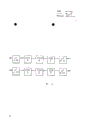
Fig. 5 is with a kind of regular tap control device that exchanges usefulness of the form illustration of block diagram, and this device comprises some direct-connected switch elements or plane;
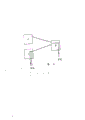
Fig. 6 then with the form illustration of block diagram one embodiment of the present of invention, comprising two switch planes and two line terminal elements.
Referring to Fig. 5, it illustrates the block diagram of a switch, and this device comprises master switcher element 51 and some line concentration way switch elements (53,55).Concentrator switch element (53,55) accumulates number exchange line still less with the number of subscriber's line, and it has guaranteed the economy use of existing switching equipment.
Actual exchange operation between the user is undertaken by change over switch element 51.In general, switch element 51 and hub element (53,55) be direct-connected similar device, thus the interconnecting module 57 of change over switch element 51 and concentrator switch element-(53,55), the switching processor 59 all have identical structure with call processing device 61.Each transfer processor 59 and call processing device 61 are that this assembly is called control element 64 through suitably combination.Each interconnecting module 57 can comprise the parallel plane of some DSM elements, and is on other interconnecting module 57 that is directly coupled in the switch.All call processing devices 61 in the switch are coupled together by each wiring 63,65, make to pass through hub (53,55) and change over switch element 51 monitoring calling procedures.
These wiring 63,65 and interconnecting module 57 are the same with wiring and the wiring between switching processor 59 and the call processing device 61 between the switching processor 59, all be the broadband, and speed are higher.Call processing device 61 is exciting switching processor 59, impels interconnecting module 57 that the data path 67 that each user is connected to the switch two ends is provided.Data path 67 is carrying data-signal together with clock signal and control signal.So just can direct communication between each switch element 64 and need not to use wiring 63 and 65.
Through the data that switch transmits, mistake wherein can detect by above-mentioned conventional method, promptly connects two and living switching plane, former switching plane, thereby can and be compared via this two planes data information.When detecting mistake thus, just make the switch control element 64 of master switcher element 51 " as major component, in order to finding out the position at mistake place, with seasonal control element 64 ' with 64 " as the subordinate element.Control element 64 " indicating the switch element 57 of oneself " and other control element 64 ' and 64 ' " fulfil aforesaid path check.Be sent to 57 ', the command signal of 57 ' " and 57 " all elements not necessarily will be via path 67, but does the speed that can improve error analysis like this.So just checked the data path 67 that is limited by switch element 57 individually, simultaneously by main controlling element 64 " collecting the result of so indivedual checks, to determine the amiss position of switch.
Can not check out the validity of data path to indivedual checks of switch element 57.Referring now to Fig. 6, the method for check data path validity is described.
Fig. 6 with symbolistic form illustration one comprise that two direct-connected switching planes 71,73 and its two ends have the device of line terminal element 75,77. Line terminal element 75,77 can transferred between the plane 71,73 " loopback " data-signal.Each plane 71,73 comprises the switch A that always receives switch B in succession.Want the validity of check data path, i.e. the validity of wiring between each switch element just need be known the state of all switch elements.
According to embodiments of the invention, we have illustrated the method for checking a data path validity, and purpose is to determine to remain to be designated as the switch of main switch.For describing, we suppose that switch B is a main switch.This main switch arrange its (may in its control element 64) will be connected thereto each switch (being switch A) remain on transition state.Therefore switch A sends a status signal for switch B, shows when state changes each time the state of each wiring between the switch A and switch B, for example comes to this during effective path in a plane when switch A sets up or remove one.Main switch B compares the state of this status signal and its each wiring, guaranteeing their unanimities, thereby guarantees the validity of path.Should be noted that to have only ability transmit status signal when detecting mistake.
Under the situation of three switches, be applicable to that the principle (as shown in Figure 6) of two switch situations is still effective.Under the situation of adjoining each switch transmission, the switch of determining the center is a main switch at status signal.
It should be understood that the method for using in conjunction with Fig. 5 explanation checks each switch element, and use in conjunction with the method for Fig. 6 explanation and examine or check wiring between each switch, just can completely examine a data path by means of system of the present invention.
Claims (5)
1, in order to be determined at the data path checking system of the mistake abort situation in a plurality of switch elements that are connected in series in the single plane, this system comprises:
Interconnection device, this device comprise many interconnection lines in order to the above-mentioned a plurality of switch elements of series coupled;
Control element, interconnecting when working in order to control described a plurality of switch element and definite described many interconnection lines, interconnecting during described work limits a data path, this data path comprises the corresponding interconnection line in several described switch elements and described many interconnection lines, in described data path, judge when a mistake is arranged, described control element is also in order to provide a detecting information, described detecting information is injected into independently and is received at each the described interconnection line of described data path and the two ends of each described switch element, with by relatively coming to determine the position of described mistake in described data path.
2, the system as claimed in claim 1 is characterized in that, described detecting information is a plurality of by the tactic data word of timing.
3, the system as claimed in claim 1, it is characterized in that, described switch element is configured to a plurality of parallel switching planes, has each data path that limits in public input and output port and the plane of respectively transferring between described public input and output port.
4, system as claimed in claim 3, it is characterized in that two parallel switching planes are arranged, these two switching planes are configured to such an extent that the time identical data are passed respectively to transfer the plane to be transmitted in work, and compare the mistake in transmitting with specified data at the public output place.
5, in order to the data transfer channel of the switch element of a plurality of series coupled in the single plane is tested and determine the method for mistake abort situation, this method may further comprise the steps:
(ⅰ) at least one in the described series coupled switch element of appointment is as main switch element, and this main switch element is stored some switch elements and the interconnective state that adjoins with described main switch element;
(ⅱ) make described main switch element arrangement comprise its each switch element, they are checked respectively by injecting a test data information in the interconnecting module in described respective switch element;
(ⅲ), the above-mentioned detecting information that is injected into make described main switch element arrange interconnecting between the switch element to be tested by being compared with the detecting information that is received on each described interconnection line and each the described switch element; With
(ⅳ) result who described main switch element is collected described each switch element is checked respectively and to the described assay of the described interconnection line between described each switch element checks the data transfer channel of a plurality of direct-coupled switch elements of cross-over connection whereby all sidedly.
Applications Claiming Priority (2)
| Application Number | Priority Date | Filing Date | Title |
|---|---|---|---|
| GB8807606.2 | 1988-03-30 | ||
| GB8807606A GB2219172B (en) | 1988-03-30 | 1988-03-30 | A data path checking system |
Publications (2)
| Publication Number | Publication Date |
|---|---|
| CN1036674A CN1036674A (en) | 1989-10-25 |
| CN1016390B true CN1016390B (en) | 1992-04-22 |
Family
ID=10634376
Family Applications (1)
| Application Number | Title | Priority Date | Filing Date |
|---|---|---|---|
| CN89101967A Expired CN1016390B (en) | 1988-03-30 | 1989-03-30 | Data path checking system |
Country Status (10)
| Country | Link |
|---|---|
| US (1) | US5042038A (en) |
| EP (1) | EP0335510A3 (en) |
| JP (1) | JPH0213095A (en) |
| KR (1) | KR890015532A (en) |
| CN (1) | CN1016390B (en) |
| AU (1) | AU615040B2 (en) |
| DK (1) | DK152089A (en) |
| FI (1) | FI891511A (en) |
| GB (1) | GB2219172B (en) |
| PT (1) | PT90166A (en) |
Families Citing this family (6)
| Publication number | Priority date | Publication date | Assignee | Title |
|---|---|---|---|---|
| US6018812A (en) * | 1990-10-17 | 2000-01-25 | 501 Charles Stark Draper Laboratory, Inc. | Reliable wafer-scale integrated computing systems |
| JP3025068B2 (en) * | 1991-09-12 | 2000-03-27 | 富士通株式会社 | ATM switch path test method |
| US5448723A (en) * | 1993-10-15 | 1995-09-05 | Tandem Computers Incorporated | Method and apparatus for fault tolerant connection of a computing system to local area networks |
| US5937032A (en) * | 1995-11-29 | 1999-08-10 | Telefonaktiebolaget L M | Testing method and apparatus for verifying correct connection of curcuit elements |
| US6928584B2 (en) * | 2000-11-22 | 2005-08-09 | Tellabs Reston, Inc. | Segmented protection system and method |
| CN101373198B (en) * | 2007-08-20 | 2011-03-16 | 电信科学技术第五研究所 | Cable test bus and switch matrix circuit |
Family Cites Families (17)
| Publication number | Priority date | Publication date | Assignee | Title |
|---|---|---|---|---|
| US3492446A (en) * | 1965-03-08 | 1970-01-27 | Ericsson Telefon Ab L M | Supervisory arrangement for detecting faults in means for selecting crossing points corresponding to switching means in a reading matrix in a telecommunication system controlled by computers |
| US3740645A (en) * | 1970-10-19 | 1973-06-19 | Teletype Corp | Circuit testing by comparison with a standard circuit |
| US4112414A (en) * | 1977-01-03 | 1978-09-05 | Chevron Research Company | Host-controlled fault diagnosis in a data communication system |
| FR2455827A1 (en) * | 1979-05-03 | 1980-11-28 | Ibm France | DIAGNOSTIC AND ALARM DEVICE FOR A DATA COMMUNICATION NETWORK |
| ZA804384B (en) * | 1979-08-10 | 1981-07-29 | Plessey Co Ltd | Digital telecommunications switching network with in-built fault identification |
| US4442502A (en) * | 1981-03-30 | 1984-04-10 | Datapoint Corporation | Digital information switching system |
| IT1156368B (en) * | 1982-06-22 | 1987-02-04 | Cselt Centro Studi Lab Telecom | MODULAR AND SELF-INSTRADING PCM SWITCHING NET FOR DISTRIBUTED COMMON TELEPHONE SELF-SWITCHERS |
| CA1203875A (en) * | 1983-06-16 | 1986-04-29 | Mitel Corporation | Switching system loopback test circuit |
| US4607365A (en) * | 1983-11-14 | 1986-08-19 | Tandem Computers Incorporated | Fault-tolerant communications controller system |
| JPH0727509B2 (en) * | 1985-04-06 | 1995-03-29 | ソニー株式会社 | Operation control method using in-device bus |
| US4710935A (en) * | 1986-04-04 | 1987-12-01 | Unisys Corporation | Parity detection system for wide bus circuitry |
| US4759019A (en) * | 1986-07-10 | 1988-07-19 | International Business Machines Corporation | Programmable fault injection tool |
| GB8618100D0 (en) * | 1986-07-24 | 1986-09-03 | Plessey Co Plc | Security arrangement |
| JPS63100843A (en) * | 1986-10-16 | 1988-05-02 | Nippon Denso Co Ltd | Communication control device |
| JPH06105284B2 (en) * | 1986-12-01 | 1994-12-21 | 株式会社日立製作所 | Method of creating test data for large scale integrated circuit |
| US4817094A (en) * | 1986-12-31 | 1989-03-28 | International Business Machines Corporation | Fault tolerant switch with selectable operating modes |
| US4937825A (en) * | 1988-06-15 | 1990-06-26 | International Business Machines | Method and apparatus for diagnosing problems in data communication networks |
-
1988
- 1988-03-30 GB GB8807606A patent/GB2219172B/en not_active Expired - Fee Related
-
1989
- 1989-03-03 EP EP19890302129 patent/EP0335510A3/en not_active Withdrawn
- 1989-03-11 KR KR1019890002993A patent/KR890015532A/en not_active Application Discontinuation
- 1989-03-28 AU AU31753/89A patent/AU615040B2/en not_active Ceased
- 1989-03-29 FI FI891511A patent/FI891511A/en not_active Application Discontinuation
- 1989-03-29 DK DK152089A patent/DK152089A/en not_active IP Right Cessation
- 1989-03-29 JP JP1077944A patent/JPH0213095A/en active Pending
- 1989-03-30 CN CN89101967A patent/CN1016390B/en not_active Expired
- 1989-03-30 PT PT90166A patent/PT90166A/en not_active Application Discontinuation
- 1989-04-17 US US07/338,744 patent/US5042038A/en not_active Expired - Fee Related
Also Published As
| Publication number | Publication date |
|---|---|
| AU615040B2 (en) | 1991-09-19 |
| EP0335510A3 (en) | 1991-03-13 |
| JPH0213095A (en) | 1990-01-17 |
| DK152089A (en) | 1989-10-01 |
| GB8807606D0 (en) | 1988-05-05 |
| CN1036674A (en) | 1989-10-25 |
| US5042038A (en) | 1991-08-20 |
| FI891511A (en) | 1989-10-01 |
| KR890015532A (en) | 1989-10-30 |
| AU3175389A (en) | 1989-10-05 |
| GB2219172A (en) | 1989-11-29 |
| EP0335510A2 (en) | 1989-10-04 |
| PT90166A (en) | 1989-11-10 |
| FI891511A0 (en) | 1989-03-29 |
| DK152089D0 (en) | 1989-03-29 |
| GB2219172B (en) | 1992-07-08 |
Similar Documents
| Publication | Publication Date | Title |
|---|---|---|
| JP4091845B2 (en) | Network documentation system with electronic modules | |
| US4723241A (en) | Data transmission arrangement including a reconfiguration facility | |
| US4685102A (en) | Switching system loopback test circuit | |
| KR100385116B1 (en) | Packet processing method using multiple fault tolerant network arrangement | |
| CN1016390B (en) | Data path checking system | |
| US4881229A (en) | Test circuit arrangement for a communication network and test method using same | |
| EP0600581B1 (en) | Multiprocessor system transferring abnormality detection signal generated in networking apparatus back to processor in parallel with data transfer route | |
| US6999410B2 (en) | Apparatus for the transmission and/or reception of data, and method for controlling this apparatus | |
| FI99255C (en) | Arrangement for connecting optical lines to a broadband communication center | |
| US6580847B2 (en) | Multistage photonic switch fault isolation | |
| JP3591383B2 (en) | Apparatus and method for diagnosing shared bus failure | |
| KR100315602B1 (en) | Apparatus for detecting connecting state of optcal line maintenance system and connecting information automatic administration method using it | |
| KR100251702B1 (en) | Fault detecting method of specific device in atm network | |
| JPH10233783A (en) | Cell transmission diagnostic system | |
| JPH02135956A (en) | Automatic confirmation test system for subscriber line | |
| JP3678265B2 (en) | Crossbar switch device and diagnostic method thereof | |
| EP0159929A2 (en) | Hybrid high speed data bus | |
| JPH01253343A (en) | Communication controller | |
| JPH02250538A (en) | Multiplex transmission network communication system | |
| JPH05289789A (en) | Input/output device | |
| JPS598452A (en) | Data transmitter | |
| JPS6365752A (en) | Test system for digital transmission line interface device | |
| JPH0491521A (en) | Method of testing communication controller | |
| JPS60220641A (en) | Local area network diagnostic system | |
| JPH0821898B2 (en) | Fault detection device in optical loop network |
Legal Events
| Date | Code | Title | Description |
|---|---|---|---|
| C06 | Publication | ||
| PB01 | Publication | ||
| C10 | Entry into substantive examination | ||
| SE01 | Entry into force of request for substantive examination | ||
| C13 | Decision | ||
| GR02 | Examined patent application | ||
| C14 | Grant of patent or utility model | ||
| GR01 | Patent grant | ||
| C19 | Lapse of patent right due to non-payment of the annual fee | ||
| CF01 | Termination of patent right due to non-payment of annual fee |