CN101606348A - Wireless communication system, its base station and travelling carriage, communication synchronization management method and timer control program thereof - Google Patents
Wireless communication system, its base station and travelling carriage, communication synchronization management method and timer control program thereof Download PDFInfo
- Publication number
- CN101606348A CN101606348A CNA2008800041112A CN200880004111A CN101606348A CN 101606348 A CN101606348 A CN 101606348A CN A2008800041112 A CNA2008800041112 A CN A2008800041112A CN 200880004111 A CN200880004111 A CN 200880004111A CN 101606348 A CN101606348 A CN 101606348A
- Authority
- CN
- China
- Prior art keywords
- timer
- travelling carriage
- period
- base station
- desired value
- Prior art date
- Legal status (The legal status is an assumption and is not a legal conclusion. Google has not performed a legal analysis and makes no representation as to the accuracy of the status listed.)
- Granted
Links
Images


Classifications
-
- H—ELECTRICITY
- H04—ELECTRIC COMMUNICATION TECHNIQUE
- H04W—WIRELESS COMMUNICATION NETWORKS
- H04W56/00—Synchronisation arrangements
-
- H—ELECTRICITY
- H04—ELECTRIC COMMUNICATION TECHNIQUE
- H04W—WIRELESS COMMUNICATION NETWORKS
- H04W56/00—Synchronisation arrangements
- H04W56/0055—Synchronisation arrangements determining timing error of reception due to propagation delay
-
- H—ELECTRICITY
- H04—ELECTRIC COMMUNICATION TECHNIQUE
- H04W—WIRELESS COMMUNICATION NETWORKS
- H04W56/00—Synchronisation arrangements
- H04W56/0005—Synchronisation arrangements synchronizing of arrival of multiple uplinks
-
- H—ELECTRICITY
- H04—ELECTRIC COMMUNICATION TECHNIQUE
- H04W—WIRELESS COMMUNICATION NETWORKS
- H04W56/00—Synchronisation arrangements
- H04W56/004—Synchronisation arrangements compensating for timing error of reception due to propagation delay
-
- H—ELECTRICITY
- H04—ELECTRIC COMMUNICATION TECHNIQUE
- H04W—WIRELESS COMMUNICATION NETWORKS
- H04W56/00—Synchronisation arrangements
- H04W56/004—Synchronisation arrangements compensating for timing error of reception due to propagation delay
- H04W56/0045—Synchronisation arrangements compensating for timing error of reception due to propagation delay compensating for timing error by altering transmission time
-
- H—ELECTRICITY
- H04—ELECTRIC COMMUNICATION TECHNIQUE
- H04W—WIRELESS COMMUNICATION NETWORKS
- H04W88/00—Devices specially adapted for wireless communication networks, e.g. terminals, base stations or access point devices
- H04W88/08—Access point devices
Abstract
[problem] in order to provide a kind of wireless communication system, wherein prevented because be used to judge travelling carriage be in the surface synchronously still surperficial asynchronous timer expiration and therefore synchronous travelling carriage be judged as and be in the possibility that the delay of the asynchronous and data that cause in surface before sending increases.[means of dealing with problems] are in the base station, (m is the integer from 1 to M regularly to calculate component computes m, and M is a natural number) transmission of travelling carriage adjusted value (TA) regularly, the self-adaptive controlled member made of timer is determined the translational speed of m travelling carriage or the time fluctuation amount of adjusted value (TA), determine the time span of the second timer of the time span of m first timer in all M first timer and m travelling carriage adaptively according to result of calculation, and they are outputed to synchro timer so that it is updated to the time span of m first timer as the timer lastest imformation, and the down link transmit block sends the down link signal that comprises the timer lastest imformation.M travelling carriage upgrades the time span of second timer according to the timer lastest imformation that is sent.
Description
Technical field
The present invention relates to utilize timer to manage synchronous wireless communication system, more specifically relate to and make the base station can control transmission wireless communication system, its base station and travelling carriage, communication synchronization management method and timer control program thereof regularly adaptively from the uplink signal of travelling carriage.
Background technology
In 3GPP Long Term Evolution (LTE), consider by (UE: (radio resource is by time and the unique zone that limits of frequency subscriber equipment) to distribute the radio resource of quadrature to keep orthogonality between the travelling carriage (UE) to each travelling carriage when transmitting and receive data; Radio resource is by the time is become distinct area with frequency partition so that distributing to different travelling carriages sets, and is overlapping thereby do not have a resource between two travelling carriages).
Transmission/reception period at uplink signal; for the interference between the travelling carriage in the sub-district of eliminating base station (Node B) (UE) so that uplink signal can be by base station (Node B) correct demodulation; the base station is called as in the guard interval of " Cyclic Prefix (CP) " regularly dropping on one from each the reception of uplink signal in a plurality of travelling carriages (UE), is very important.Simultaneously, no matter actual being maintained whether synchronously of data transmission/reception dropped in the preset time section (that is, at the timer run duration) if receive regularly, then all suppose synchronously to be guaranteed.Based on this supposition, receiving the state that regularly drops in the timer period is judged as and infers synchronous regime (deemedin-sync state) (promptly, think that travelling carriage is a uplink synchronisation), regularly do not drop in the timer period (promptly and receive, timer expiration) state is judged as the lock-out state of inferring (deemed out-of-sync state) (that is, thinking that travelling carriage is not a uplink synchronisation).
Be judged as and be in the travelling carriage (UE) of inferring in the lock-out state sent asynchronous RACH (non-synchronized random access channel) before sending uplink signal, in asynchronous RACH, common radio resource is used in a plurality of travelling carriages (UE) competition.Travelling carriage receive from the base station subsequently be used to regulate its send timing adjusted value (TA) regularly (timing advance, TA).According to TA, travelling carriage is regulated it and is sent regularly and finally make uplink synchronization (that is, the base station is in and receives uplink signal in the CP).
Because each travelling carriage (UE) must be guaranteed when it sends uplink signal synchronously, so or by constant interval, perhaps (for example, the rapid variation of the gait of march of travelling carriage) generation triggers, and regularly adjusted value (TA) is notified to each travelling carriage from the base station by particular event.From timing adjusted value (TA) be updated recently play travelling carriage be judged as turn back to till the lock-out state fiducial time section or as the sub-district particular value system information from the base station notice, perhaps be fixing value by pre-defined.Locate by using timer to monitor this fiducial time in base station and each travelling carriage (UE).To after date (that is, when the said reference time period expires), travelling carriage (UE) is judged as and is converted to the lock-out state of inferring from inferring synchronous regime at timer.
Infer synchronous regime or be in the lock-out state of inferring in order to judge that travelling carriage (UE) is in, the base stations control number equals the timer of the number of travelling carriage (UE) at one's disposal.The timer that m the timer that the base station is held (wherein m is the integer between 1 to M, and M is the natural number of number of the travelling carriage (UE) of indication BTS management) held corresponding to m travelling carriage (UE).
A plurality of timers that the base station is controlled are set to identical time span, and the timer that a plurality of travelling carriage is held also is like this.Base station timer and travelling carriage timer are set to such timer length: this timer length makes that at full throttle (travelling carriage of for example, 350km/h) advancing (UE) can guarantee synchronously in all travelling carriages (UE) that the base station is supported.Therefore timer length is shorter than will the become minimum time length of lock-out of this travelling carriage (UE).The judgement of inferring synchronous regime and inferring between the lock-out state is that the state that only depends on timer is made, and the do not consider travelling carriage actual travel speed of (UE).Non-patent literature 1 discloses regulates the example that sends processing regularly during uplink signal in above-mentioned 3GPP Long Term Evolution (LTE) transmits.
When generation will send to the data of base station, be in the travelling carriage (UE) of inferring in the synchronous regime and at first utilize the special-purpose radio resource of this travelling carriage (UE) to send dispatch request (SR) is used for sending data with request radio resource to the base station.Can be used for assigning a kind of method of the special-purpose radio resource of travelling carriage (UE) is periodically to be in the travelling carriage (UE) of inferring in the synchronous regime to each to assign the radio resource that is used for sending SR.On the other hand, when being in travelling carriage (UE) the transmission SR that infers in the lock-out state, it at first sends asynchronous RACH and reception is used to control the timing adjusted value (TA) that sends timing, and appointment simultaneously is used for sending radio resource SR, this travelling carriage (UE) special use.
From above-mentioned clearly visible, be in the travelling carriage (UE) of inferring in the lock-out state and be in the travelling carriage of inferring in the synchronous regime and compare can initiating data and will experience longer delaying (latency) (the perhaps delay that causes owing to the stand-by period) before sending.This is because preceding a kind of travelling carriage also needs a step that sends asynchronous RACH, could carry out the step that sends SR then.In addition, owing to the orthogonality that does not guarantee for asynchronous RACH between the travelling carriage (UE), so may clash between the travelling carriage (UE).If clash, the asynchronous RACH that is then sent may not detected by the base station, and travelling carriage (UE) must be retransmitted and send asynchronous RACH in this case.This has further increased delays.
Non-patent literature 1:3GPP RAN WG2 Contribution[R2-063401.doc NTTDoCoMo]
http://www.3gpp.org/ftp/tsg_ran/WG2_RL2/TSGR2_56/Documents/
Non-patent literature 2:3GPP RAN WG1 Contribution[R1-063377.doc Nokia]
http://www.3gpp.org/ftp/tsg_ran/WG1_RL1/TSGR1_47/Docs/
Non-patent literature 3:3GPP RAN WG1 Contribution[R1-063405.doc Siemens]
http://www.3gpp.org/ftp/tsg_ran/WG1_RL1/TSGR1_47/Docs/
In above-mentioned prior art, the travelling carriage (UE) that timer length was based on fast and carried out (for example, with 350km/h speed) guarantees what the synchronous time was set.This has caused such problem, that is, even in fact uplink synchronisation is maintained, static or also may be judged as to be in when timer expires with the travelling carriage (UE) that low speed is advanced and infer in the lock-out state.
In addition, must expire at timer but be sent out during the actual period that is maintained synchronously if locate to occur other data and uplink signal at travelling carriage (UE), then delaying before these data can be sent out becomes longer.
This is because travelling carriage (UE) static or that slowly move is judged as lock-out based on timer, even it is actually synchronous and can utilizes the radio resource that is assigned to it specially to send dispatch request (SR).In this case, travelling carriage need at first send asynchronous RACH receiving the timing adjusted value (TA) from base station (Node B), so that it can be assigned to be used for sending according to timing adjusted value (TA) radio resource of SR.
(purpose of the present invention)
An object of the present invention is to provide a kind of wireless communication system, its base station and travelling carriage, communication synchronization management method and timer control program thereof, it can be controlled adaptively at each travelling carriage and be used to judge that travelling carriage is in infers synchronous regime or be in the timer length of inferring the lock-out state, thereby the travelling carriage of actual synchronization being judged as be in the possibility of inferring the lock-out state reaches bottom line.
Another object of the present invention provides a kind of wireless communication system, its base station and travelling carriage, communication synchronization management method and timer control program thereof, and what it can reduce that during the period that is in the travelling carriage actual synchronization of inferring lock-out state uplink signal sends delays.
Summary of the invention
According to the first example technique scheme of the present invention, a kind of base station of carrying out the wireless communication system of radio communication between travelling carriage and base station comprises:
Timer units, this timer units is set a period, during this period, at base station place to from the reception of the uplink signal of travelling carriage being guaranteed synchronously regularly, and according to the overdue generation of this period whether this timer units, the judgement travelling carriage is in to infer synchronous regime or be in infers the lock-out state, is guaranteed synchronously in inferring synchronous regime, is not guaranteed synchronously in inferring the lock-out state; And
The timer control unit, this timer control unit can be determined the period of timer units and upgrade timer units at each travelling carriage according to the state of travelling carriage.
According to the second example technique scheme of the present invention, a kind of travelling carriage of carrying out the wireless communication system of radio communication between travelling carriage and base station comprises:
Timer units, this timer units is set a period, during this period, at base station place to from the reception of the uplink signal of travelling carriage being guaranteed synchronously regularly, and according to the overdue generation of this period whether this timer units, the judgement travelling carriage is in to infer synchronous regime or be in infers the lock-out state, is guaranteed synchronously in inferring synchronous regime, is not guaranteed synchronously in inferring the lock-out state; And
The timer control unit, this timer control unit can be determined timer length and upgrade timer units according to the state of travelling carriage.
According to the 3rd example technique scheme of the present invention, a kind of wireless communication system of carrying out radio communication between travelling carriage and base station comprises:
Base station and travelling carriage
This base station and travelling carriage comprise timer units, this timer units is set a period, during this period, at base station place to from the reception of the uplink signal of travelling carriage being guaranteed synchronously regularly, and according to the overdue generation of this period whether this timer units, the judgement travelling carriage is in to infer synchronous regime or be in infers the lock-out state, is guaranteed synchronously in inferring synchronous regime, is not guaranteed synchronously in inferring the lock-out state; And
Any one place at least in base station and travelling carriage
Comprise the timer control unit, this timer control unit can be determined in base station and the travelling carriage at least the timer length of any one adaptively and upgrade timer units at each travelling carriage according to the state of travelling carriage.
According to the 4th example technique scheme of the present invention, the communication synchronization management method in a kind of wireless communication system of carrying out radio communication between travelling carriage and base station comprises:
At base station and travelling carriage place
Has the timer step, this timer step is set a period, during this period, at base station place to from the reception of the uplink signal of travelling carriage being guaranteed synchronously regularly, and according to the overdue generation of period whether this timer step, utilize timer to judge that travelling carriage is in to infer synchronous regime or be in and infer the lock-out state, in inferring synchronous regime, be guaranteed synchronously, in inferring the lock-out state, be not guaranteed synchronously; And
At least one place in base station and travelling carriage
Determine in base station and the travelling carriage period of using in the timer step at any one place at least adaptively and upgrade timer at each travelling carriage according to the state of travelling carriage.
According to the 5th example technique scheme of the present invention, a kind of computer implemented timer control program by the wireless communication system of execution radio communication between travelling carriage and base station is used for working on the base station,
Make computer carry out following function
Set a period, during this period, at base station place to from the reception of the uplink signal of travelling carriage being guaranteed synchronously regularly, and whether according to the overdue generation of period, utilizing timer to judge that travelling carriage is in infers synchronous regime or is in the lock-out state of inferring, in inferring synchronous regime, be guaranteed synchronously, in inferring the lock-out state, be not guaranteed synchronously; And
The timer controlled function, this timer controlled function can be determined timer length and upgrade timer at each travelling carriage according to the state of travelling carriage.
According to the 6th example technique scheme of the present invention, a kind of by the computer implemented timer control program of between travelling carriage and base station, carrying out the wireless communication system of radio communication, be used on travelling carriage, working
Make computer carry out following function
Set a period, during this period, at base station place to from the reception of the uplink signal of travelling carriage being guaranteed synchronously regularly, and whether according to the overdue generation of period, utilizing timer to judge that travelling carriage is in infers synchronous regime or is in the lock-out state of inferring, in inferring synchronous regime, be guaranteed synchronously, in inferring the lock-out state, be not guaranteed synchronously; And
The timer controlled function, this timer controlled function can be determined timer length and upgrade timer according to the state of travelling carriage.
Effect of the present invention is, can reduce to infer synchronous regime or be in the expiring of timer of inferring the lock-out state and the probability of delaying increasing before data send when being judged as lock-out based on being used to judge that travelling carriage is at the travelling carriage of actual synchronization.This is because the present invention can control the timer length of each travelling carriage adaptively according to the gait of march of travelling carriage.
Description of drawings
Fig. 1 is the block diagram that is used to illustrate first exemplary embodiment of the present invention;
Fig. 2 is the block diagram that is used to illustrate the synchro timer of first exemplary embodiment according to the present invention;
Fig. 3 is the block diagram that is used to illustrate the self-adaptive controlled member made of timer of first exemplary embodiment according to the present invention;
Fig. 4 is the block diagram that is used to illustrate the method for the gait of march of estimating travelling carriage;
Fig. 5 is used to illustrate the block diagram that receives regularly and send the relation between the timing adjusted value regularly;
Fig. 6 is used to illustrate that qualification according to first embodiment of the invention is used for determining the diagrammatic sketch of the form of the gait of march of timer length and the relation between the timer length;
Fig. 7 is the diagrammatic sketch that is used to illustrate the method for definite timer length of first exemplary embodiment according to the present invention;
Fig. 8 is the diagrammatic sketch that is used to illustrate the method for definite timer length of first exemplary embodiment according to the present invention;
Fig. 9 is the diagrammatic sketch that is used to illustrate the process of definite timer length of first exemplary embodiment according to the present invention;
Figure 10 is the block diagram that is used to illustrate the self-adaptive controlled member made of the first exemplary embodiment timer according to the present invention;
Figure 11 is the diagrammatic sketch that the qualification that is used to illustrate first exemplary embodiment according to the present invention is used for determining the form of the timing adjusted value of timer length and the relation between the timer length;
Figure 12 is the diagrammatic sketch that is used to illustrate the method for definite timer length of first exemplary embodiment according to the present invention;
Figure 13 is the diagrammatic sketch that is used to illustrate the method for definite timer length of first exemplary embodiment according to the present invention;
Figure 14 is the block diagram that is used to illustrate the self-adaptive controlled member made of timer of first exemplary embodiment according to the present invention;
Figure 15 is the flow chart that the operation of the base station of first exemplary embodiment according to the present invention is shown;
Figure 16 is the flow chart that the operation of the base station of first exemplary embodiment according to the present invention is shown;
Figure 17 is the flow chart that the operation of the base station of first exemplary embodiment according to the present invention is shown;
Figure 18 is the block diagram that the hardware configuration of the travelling carriage of first exemplary embodiment according to the present invention and base station is shown;
Figure 19 is the block diagram that is used to illustrate second exemplary embodiment of the present invention;
Figure 20 is the block diagram that is used to illustrate the self-adaptive controlled member made of timer of second exemplary embodiment according to the present invention;
Figure 21 is the block diagram that is used to illustrate the self-adaptive controlled member made of timer of second exemplary embodiment according to the present invention;
Figure 22 is the block diagram that is used to illustrate the self-adaptive controlled member made of timer of second exemplary embodiment according to the present invention;
Figure 23 is the diagrammatic sketch that is used to illustrate the process of definite timer length of second exemplary embodiment according to the present invention;
Figure 24 is the block diagram that is used to illustrate the 3rd exemplary embodiment of the present invention;
Figure 25 is the block diagram that is used to illustrate the self-adaptive controlled member made of timer of the 3rd exemplary embodiment according to the present invention;
Figure 26 is the diagrammatic sketch that is used to illustrate the process of definite timer length of the 3rd exemplary embodiment according to the present invention;
Figure 27 is the block diagram that is used to illustrate the 4th exemplary embodiment of the present invention;
Figure 28 is the block diagram that is used to illustrate the self-adaptive controlled member made of timer of the 4th exemplary embodiment according to the present invention;
Figure 29 is the diagrammatic sketch that is used to illustrate the process of definite timer length of the 4th exemplary embodiment according to the present invention;
Figure 30 is the block diagram that the system configuration of the wireless communication system of the 5th exemplary embodiment according to the present invention is shown;
Figure 31 is the block diagram that the system configuration of the wireless communication system of the 6th exemplary embodiment according to the present invention is shown;
Figure 32 is the block diagram that the system configuration of the wireless communication system of the 7th exemplary embodiment according to the present invention is shown;
Figure 33 is the diagrammatic sketch that the summary of the wireless communication system of the 8th exemplary embodiment according to the present invention is shown;
Figure 34 is the diagrammatic sketch that the summary of the wireless communication system of the 9th exemplary embodiment according to the present invention is shown; And
Figure 35 is the diagrammatic sketch that the summary of the wireless communication system of the tenth exemplary embodiment according to the present invention is shown.
Embodiment
Describe the present invention in detail referring now to accompanying drawing.
At first, in exemplary embodiment of the present invention, setting is used to judge that travelling carriage is in the initial value T that infers synchronous regime or be in the timer of inferring the lock-out state during the synchronous period of the station that can guarantee fast moving
TM0This can utilize with the similar method of normally used method and finish.In 3GPP LTE, 350[km/h] gait of march be assumed that the reference speed of setting timer length.
In non-patent literature 2, the tolerance limit that correctly detects the required transmission of uplink signal deviation regularly is estimated as about 1[usec].In non-patent literature 3, lose synchronous worst case be assumed to be occur in owing to sending 1[usec regularly] deviation lose when synchronous.
Utilize these values as benchmark, each exemplary embodiment is used about 1.5[sec] as the initial value T of timer
TM0This is make to send regularly at 350[km/h] gait of march lower deviation 1[usec] time span.The timer length that m the first timer (first timer #m) that base station (Node B) held set is identical with timer length to the second timer setting held by m travelling carriage (UE#m), wherein m is the integer between 1 to M, and M is the natural number of number that expression is subjected to the travelling carriage of BTS management.The accidental access signal that is in the travelling carriage transmission in the lock-out state is made of the sequence of selecting at random from predetermined number aim sequence (for example, Zadoff-Chu sequence).
" synchronously " used herein refers to a kind of like this state: send regularly and controlled by the base station, thereby make the reception that sends to the uplink signal of base station from travelling carriage regularly be in the desired precision.Receive regularly according to such as the factor of distance between travelling carriage and the base station (that is the position of travelling carriage) and so on and different.Therefore, the gait of march of travelling carriage is high more, and it is just big more to receive variation regularly, and it is just short more therefore to keep the time span of " synchronously ".
" infer synchronous regime " and " inferring the lock-out state " between difference to be based on timer still be to have expired to judge in operation." inferring synchronous regime " is the state that timer is moving, and based on this fact, judgement can guarantee the up link between travelling carriage and the base station." inferring the lock-out state " is the state that timer has expired, and based on this fact, judgement can not guarantee the uplink synchronisation between travelling carriage and the travelling carriage.This means that even be judged as when being in " inferring the lock-out state " at travelling carriage, it also may be actually synchronous.On the contrary, even be judged as when being in " inferring synchronous regime " at travelling carriage, it also may be actually lock-out.
Though following exemplary embodiment is to describe at the 3GPP LTE as example, object of the present invention is not limited to LTE, and can be WLAN, WiMAX or other similar techniques.Present invention can be applied to any such system: this system requirements is based on the synchronous connection of TDM, and the deviation between timer wherein may taking place and receiving regularly.
(first exemplary embodiment)
Fig. 1 is the block diagram that the system configuration of the wireless communication system of first exemplary embodiment according to the present invention is shown.In this exemplary embodiment, the determining of the length of the second timer that first timer of holding to the calculating of the desired value that is used for determining timer length and to the base station and travelling carriage (UE) are held carried out by the base station.
With reference to figure 1, travelling carriage (UE) 101 comprises that judging part 103, baseband signal generate parts 104, uplink signal generates parts 105, sends information input part 106, signaling component 107, second timer 108 and down link signal demodulation parts 109.
At travelling carriage (UE#m) 101 places, (Node B) 102 receives the down link received signal S that comprises the timing adjusted value (TA) that is used for up link transmission timing to down link signal demodulation parts 109 from the base station
DLTX, and output: with corresponding regularly adjusted value (TA) S that reproduces of the timing adjusted value (TA) that receives at the travelling carriage place
RTAAt timing adjusted value (TA) the timer control information S that the notice second timer is reset when (Node B) notice is come from the base station
TCIAnd with the timer lastest imformation corresponding institute reproduction timer lastest imformation S of new timer length of indication under the situation that second timer is updated
RTUI
Second timer 108 is according to timer control information S
TCIWith the reproduction timer lastest imformation S of institute
RTUIWork.As the reproduction timer lastest imformation S of institute
RTUIWhen being transfused to, second timer 108 upgrades the length of second timers, and output is in to infer synchronous regime or be in the information of inferring the lock-out state about travelling carriage (UE) #m and is used as state information S
SISecond timer 108 can be carried out output state information S in the following manner
SIProcessing: for example, it only is in when inferring the lock-out state just output state information S at travelling carriage
SI, and be in when inferring synchronous regime not output state information S at travelling carriage
SI
As the transmission information S that will send to base station (Node B) 102
INFOWhen being transfused to, judging part 103 is according to state information S
SISwitch connection.More specifically, if synchronous regime is inferred in this information indication, then it handovers the connection to uplink signal and generates parts 105, if the lock-out state is inferred in this information indication, then it handovers the connection to baseband signal and generates parts 104.
Baseband signal generates parts 104 to have and generates and output is used for the function of the baseband signal of communicating by letter with base station (Node B) 102.Here and in the example of using in other exemplary embodiments described below, accidental access signal S
RSBe generated and export so that (Node B) receives the timing adjusted value (TA) that is used for the simultaneous uplink signal from the base station.
Uplink signal generates parts 105 according to regularly adjusted value (TA) S of reproduce
RTARegulate sending regularly, and generate and output comprises transmission information S
INFOUplink signal S
US
Send signal S as up link
ULTX, signaling component 107 is in the situation of inferring synchronous regime at travelling carriage and issues and serve downlink signal S
US, send accidental access signal S under the situation of inferring the lock-out state and be at travelling carriage
RS
With reference to figure 1, base station (Node B) 102 comprises judging part 110, baseband signal demodulation parts 111, uplink signal demodulation parts 112, timing calculating unit 113, the self-adaptive controlled member made 114 of timer, synchro timer 115 and down link transmit block 116, and wherein synchro timer 115 can rename as the time unifying timer.
(Node B) 102 places in the base station, judging part 110 is according to the state information S of the state of indication travelling carriage (UE) #m
SISwitch connection.More specifically, if synchronous regime is inferred in the indication of this information, it then handovers the connection to uplink signal demodulation parts 112, and if the lock-out state is inferred in this information indication, it then handovers the connection to baseband signal demodulation parts 111.
The up link received signal S that baseband signal demodulation parts 111 receive corresponding to baseband signal
ULTXInput, and have to the input up link received signal S
ULTXSeparate the function of mediation output.Here with other exemplary embodiments described below in the example used, baseband signal demodulation parts 111 receive corresponding to accidental access signal S
RSUp link received signal S
ULTXAs input, and the information that output indicates the sequence that surpasses predefined detection threshold is used as inserting at random detection information
SRDI
112 pairs of uplink signal demodulation parts and uplink signal S
USCorresponding up link received signal S
ULTXCarry out demodulation, and output and the information of transmission S
INFOThe corresponding transmission information S that reproduces
RINFO
Regularly calculating unit 113 has TA calculating unit 1131 and TA memory unit 1132.Regularly calculating unit 113 uses TA calculating unit 1131 to detect up link received signal S
ULTXReception regularly (that is, receive deviation regularly), and calculate timing adjusted value (TA) S that will be notified to travelling carriage (UE) #m based on detected receptions timing
TAIt is stored in resulting TA in the TA memory unit 1132 subsequently and exports this TA S
TA
The self-adaptive controlled member made 114 of timer uses up link received signal S
ULTXAnd/or timing adjusted value (TA) S
TAIn both or any one as input, determine the length of the second timer of first timer #m and travelling carriage (UE) #m.It exports resulting timer length subsequently as timer lastest imformation S
TUI, and output notifies the information of first timer #m replacement to be used as timer control information S by send regularly adjusted value (TA) to travelling carriage (UE) #m
TCI
Synchro timer 115 with M first timer is according to timer lastest imformation S
TUIWith timer control information S
TCIWork, and output is in to infer synchronous regime or be in the information of inferring the lock-out state about travelling carriage (UE) #m and is used as state information S
SI
Down link transmit block 116 is according to state information S
SIGenerate and send downlink transmitted signal S
DLTXDownlink transmitted signal S
DLTXComprise regularly adjusted value (TA) S under the situation of synchronous regime inferring
TAWith timer lastest imformation S
TUI, and under the situation of inferring the lock-out state, comprise regularly adjusted value (TA) S
TA, timer lastest imformation S
TUIInsert detection information S at random
RDI
Synchro timer is made of M first timer 117, as shown in Figure 2.First timer #m is corresponding to the second timer of travelling carriage (UE) #m.
When the length of the second timer of determining first timer #m and travelling carriage (UE) #m, the self-adaptive controlled member made 114 of timer uses gait of march S
VIAnd/or transmission timing transition information S
TADIIn both or any one as index, gait of march S wherein
VIBe the result who obtains by the gait of march of estimating travelling carriage (UE) #m, send regularly transition information S
TADIBe by calculating regularly the result that the time fluctuation amount of adjusted value (TA) obtains.
Fig. 3,10 and 14 shows respectively and is using gait of march; The time fluctuation amount of timing adjusted value (TA); The structure of the self-adaptive controlled member made of timer when perhaps the time fluctuation amount of gait of march and timing adjusted value (TA) is as index.
The self-adaptive controlled member made 114 of the timer of Fig. 3 comprises that velocity estimation parts 118 and timer determine parts 121, and wherein velocity estimation parts 118 are by using up link received signal S
ULTXEstimate the gait of march S of travelling carriage (UE) #m as input
VI, timer determines that parts 121 are by using gait of march S
VIDetermine the length of the second timer of the length of first timer #m and travelling carriage (UE) #m as input.
Here a kind of method of estimation of operable gait of march is according to Doppler frequency F
d[Hz] estimates its (F wherein
dBe to be equal to or greater than 0 real number).
Doppler frequency F
dCan utilize the amount of phase rotation θ [rad] (wherein θ is equal to or greater than 0 real number) of known frequency pilot sign to estimate.For example, as shown in Figure 4, as supposition P
1And P
2Be respectively and the corresponding received signal vector of first and second frequency pilot signs, and T
pBe P
1And P
2Between time domain interval the time, the amount of phase rotation θ can obtain according to following relational expression: θ={ cos
-1(P
1P
2)/T
p(wherein being inner product).Utilize the θ value that obtains like this, Doppler frequency F
dCan obtain according to following relational expression: F
d=θ/{ 2 π T
p.In addition, utilize the Doppler frequency F that obtains like this
d, can calculate gait of march v:v=F according to following relational expression
dλ=F
d(c/f), wherein λ is wavelength [m], and c is the light velocity 3 * 10
8[m/s], and f is carrier frequency [Hz].
Fig. 5 show the detected reception in base station (Node B) regularly and will be notified to travelling carriage (UE) be used to send exemplary relation between the timing adjusted value (TA) regularly.
In Fig. 5, Cyclic Prefix (CP) is added to the head of uplink signal (1 frame).Desirable reception regularly is the head that the head of CP appears at each time slot.Actual detected to reception regularly and ideal receive deviation x[us regularly] since the factor such as the deviation that moves and send timing of travelling carriage (UE) #m take place.
Sending departure regularly can utilize in following two kinds of methods any to be notified to travelling carriage (UE): a kind of method is notice x[us] absolute value as timing adjusted value (TA); Another kind is that notice is by to x[us] time of carrying out cuts apart the value that obtains and is used as timing adjusted value (TA).In the method for notice time partition value, the once transmission of notice timing adjusted value (TA) will be shifted to an earlier date or be postponed the y[us of predetermined constant step size] unit.Thereby, under the situation of method of notice time partition value, send regularly and can utilize 1 bit to send, with notice for example: if the value that is sent be 0 fixed value will be by y[us in advance], if the value that is sent be 1 fixed value will be delayed y[us].In the case, if the transmission timing offset amount that Practical Calculation goes out is+4 * y[us], then be worth 0 and be sent out four times, will be shifted to an earlier date 4 * y[us altogether so that send regularly].
The another kind of method that has these two kinds of methods of combination.A kind of possible combination is a method of using the notice absolute value when setting the initial value of transmission timing, then uses the method for notice time partition value when upgrading the transmission timing.
Fig. 6 to 8 is the diagrammatic sketch of method of determining and upgrade the length of first and second timers that are used to illustrate according to first exemplary embodiment.
The self-adaptive controlled member made 114 of timer is assumed that and comprises that velocity estimation parts 118 and timer determine parts 121 (Fig. 3).Timer determines that parts 121 are based on gait of march S
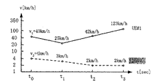
VIAnd the form of the relation between pre-defined gait of march and the timer length is determined the length of first and second timers.This exemplary embodiment is used the definition gait of march shown in Figure 6 and the form of the relation between the timer length.
Each timer length in the form of Fig. 6 is to utilize following formula (1) to calculate, and indicate be assumed to be at 350[km/h] gait of march lower deviation 1.5[sec] the identical transmission timing value of transmission timing value in, the time of the deviation that causes under each gait of march [sec], wherein 350[km/h] be the reference speed of when setting initial value, using.
(formula 1)
D wherein
TA[usec] sends deviate regularly; V[km/h] be the gait of march of travelling carriage (UE); T[sec] be to cause D
TATime of deviation; And 6.7[usec/km] be round-trip delay (RTD), this is the propagation delay that causes between base station (Node B) and travelling carriage (UE).
Formula (1) is used to create form as shown in Figure 6.This form is by the increment of the threshold value of at first determining gait of march v and sends timing offset D
TABut receiving amount, and subsequently with in the resulting value substitution formula (1) to calculate t, create.The t value of Huo Deing is used as the line feed threshold value like this.
In this exemplary embodiment, the velocity estimation parts 118 of base station (Node B) are estimated the gait of march of two travelling carriages (UE# 1, UE#2) at interval by regular time, as shown in Figure 7.Timer determines that parts 121 determine at each (t constantly
0, t
1, t
2, t
3) length of first and second timers.Based on these results, control first and second timers adaptively.Here suppose the initial value T that the first and second all timers are right
TM0All be 1.5[sec], this is to determine to deal with 350[km/h] the time span of gait of march.
In Fig. 7, will at first consider travelling carriage (UE) #1.t
0The time gait of march be 40[km/h].The initial value that this is right far below all first and second timers at gait of march 350[km/h], mean to continue the long time synchronously.In the case, can make the length of second timer of first timer # 1 and travelling carriage (UE) #1 longer.
With reference to the form of figure 6,40[km/h] gait of march between 30[km/h] to 120[km/h] between, so the length of the second timer of first timer # 1 and travelling carriage (UE) #1 is confirmed as 4.5[sec].
Base station (Node B) shows regularly that to travelling carriage (UE) #1 notice the length of adjusted value (TA) and second timer will be updated to 4.5[sec] the timer lastest imformation.After sending this notice, it is updated to 4.5[sec with the length of first timer # 1 immediately] and make first timer # 1 restart work.
Travelling carriage (UE) #1 reproducing regularly adjusted value (TA) and timer lastest imformation, is updated to 2.9[sec with the length of second timer to the down link signal demodulation], and make second timer restart work.
Similarly, at t=t
1, t
2, t
3The time first timer # 1 and travelling carriage (UE) #1 the length of second timer be confirmed as 17.9[sec respectively], 4.5[sec] and 1.5[sec].When timer length was updated, the new length of the second timer that base station (Node B) just will be determined like this was notified to travelling carriage (UE) #1.
Next, will consider travelling carriage (UE) #2.Its initial value is identical with travelling carriage (UE) #1, that is, and and 1.5[sec].t
0The time gait of march be 4[km/h].This speed ratio travelling carriage (UE) #1's is also low.Can make timer length longer, because will continue synchronously than the longer time of travelling carriage (UE) #1.
With reference to the form of figure 6,4[km/h] gait of march between 0[km/h] to 5[km/h] between, so the length of the second timer of first timer # 2 and travelling carriage (UE) #2 is confirmed as 107.5[sec].
Base station (Node B) shows regularly that to travelling carriage (UE) #2 notice the length of adjusted value (TA) and second timer will be updated to 107.5[sec] the timer lastest imformation.After sending this notice, it is updated to 107.5[sec with the length of first timer # 2 immediately] and make first timer # 2 restart work.
Travelling carriage (UE) #2 reproducing regularly adjusted value (TA) and timer lastest imformation, is updated to 107.5[sec with the length of second timer to the down link signal demodulation], and make second timer restart work.
Similarly, to t=t
1, t
2, t
3The time the estimation of gait of march provide 3[km/h respectively], 2[km/h] and 2[km/h], this and t
0The result much at one.Therefore, the timer in the observation period of Fig. 7 is set and is confirmed as remaining at 107.5[sec], and without any need for renewal.Whenever timing adjusted value (TA) is calculated or is notified when coming, base station (Node B) and travelling carriage (UE) #2 just repeat respectively to reset first timer # 2 or second timer length with make separately timer restart the processing of work.
Fig. 8 shows the result who determines timer length as described above.
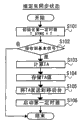
Fig. 9 is the diagrammatic sketch that illustrates in the processing of carrying out according to this exemplary embodiment base station (Node B) and travelling carriage (UE) #m with the definite relevant part of the length of the second timer of first timer #m and travelling carriage (UE) #m.
After the uplink signal 1 that receives from travelling carriage (UE) #m, base station (Node B) calculates regularly adjusted value (TA), estimates gait of march, and the length of the second timer of definite first timer #m and travelling carriage (UE) #m.Base station (Node B) is notified to travelling carriage (UE) #m via the length of the second timer after down link signal 1 general's timing adjusted value (TA) and the renewal subsequently.After travelling carriage (UE) #m sends down link signal 1, base station (Node B) reset immediately first timer #m and make first timer #m restart work.
Travelling carriage (UE) #m to down link signal 1 demodulation to reproduce regularly adjusted value (TA) and second timer length through upgrading.After second timer is updated to the timer length of being reproduced, travelling carriage (UE) #m replacement second timer and make second timer restart work.Travelling carriage (UE) #m regulates according to the timing adjusted value (TA) that is reproduced subsequently and sends regularly, and sends uplink signal 2.
Can be used for estimating that the possible signal of gait of march is the known signal (reference signal: RS), perhaps be sent out the quality (cqi: the RS that is used for CQI measurement CQI) that allows base station (Node B) to measure the up link circuit that sends via UL-SCH that is used for the uplink signal that comprises data and control information from travelling carriage (UE) #m is carried out demodulation that sends via uplink shared channel (UL-SCH) by the velocity estimation parts of base station (Node B).In addition, possible the signal that is used to notify timer to upgrade is to be used to control the 1st layer/the 2nd layer signal (L1/L2 control signaling) via what downlink sharied signal channel (DL-SCH) sent, perhaps via the signal (physical down link sharing channel: PDSCH) that is used for the data transmission of DL-SCH transmission.
The self-adaptive controlled member made 114 of the timer of Figure 10 comprises that change calculating unit 119 and timer determine parts 122, wherein changes calculating unit 119 by using regularly adjusted value (TA) S
TACalculate and export the regularly time fluctuation amount S of adjusted value (TA) as input
TADI, timer determines that parts 122 are by using the regularly time fluctuation amount S of adjusted value (TA)
TADIDetermine the length of the second timer of the length of first timer #m and travelling carriage (UE) #m as input.
In the method for using regularly the time fluctuation amount of adjusted value (TA) as the index of determining timer length according to the present invention, if it is notified as timing adjusted value (TA) to send the absolute value of departure regularly, then be used directly as the regularly time fluctuation amount of adjusted value (TA) in the amount of observing the change of timing adjusted value (TA) in the period.On the other hand, if it is notified as timing adjusted value (TA) to send the time partition value of departure regularly, then regularly the time partition value of adjusted value (TA) is added up reproducing transmission actual deviation amount regularly, and is used as the regularly time fluctuation amount of adjusted value (TA) in the amount of observing the transmission change regularly of being reproduced in the period.
Timer is determined time fluctuation amount and the time fluctuation amount of pre-defined timing adjusted value (TA) and the form of relation timer length between of parts 122 based on timing adjusted value (TA), determines the length of first and second timers.In description, notify the regularly method of the departure of adjusted value (TA) with the form of absolute value with considering to this exemplary embodiment.
Each timer length in the form of Figure 11 sends departure regularly and the relation of the difference between the gait of march that expection under this departure takes place during being based on observation interval, utilizes following formula (2) to (4) to calculate.
(formula 2)
(formula 3)
(formula 4)
Wherein, in formula (2), D
TA[usec] sends deviate regularly; V[km/h] be the gait of march of travelling carriage (UE); T[sec] be to cause D
TATime of deviation; And 6.7[usec/km] be round-trip delay (RTD), this is the propagation delay that causes between base station (Node B) and travelling carriage (UE).In formula (3), Δ d[usec] be at Δ t[sec] period during the transmission departure regularly that causes.
The change calculating unit of supposing base station (Node B) by regular time at interval (that is, every 10[sec]) be the time fluctuation amount that travelling carriage (UE) #1 calculates timing adjusted value (TA), and the result is shown in Figure 12.At each moment (t
0, t
1, t
2, t
3), timer determines that parts determine the length of first and second timers and adaptively control first and second timers.Here suppose the initial value T of first and second timers
TM0Be 1.5[sec], this is to be determined to tackle 350[km/h] the time span of gait of march.
The t that calculates by the change calculating unit of base station (Node B)
0The time the time fluctuation amount of timing adjusted value (TA) be 2.18[usec/10sec].With reference to the form of Figure 11, variation is between 0.56[usec/10sec] to 2.23[usec/10sec] between, therefore can make timer length be longer than initial value 1.5[sec].Based on this form, the length of the first and second timer # 1 is confirmed as 4.5[sec].
Base station (Node B) shows regularly that to travelling carriage (UE) #1 notice the length of adjusted value (TA) and second timer will be updated to 4.5[sec] the timer lastest imformation.After sending this notice, it is updated to 4.5[sec with the length of first timer # 1 immediately] and make first timer # 1 restart work.
Travelling carriage (UE) #1 reproducing regularly adjusted value (TA) and timer lastest imformation, is updated to 2.9[sec with the length of second timer to the down link signal demodulation], and make second timer restart work.
Similarly, at t=t
1, t
2, t
3, base station (Node B) is 1.45[usec/10sec according to the result that the calculating to the time fluctuation amount of timing adjusted value (TA) obtains], 1.92[usec/10sec] and 3.28[usec/10sec].With reference to the form of Figure 11, the length that can determine first and second timers is respectively 4.5[sec], 4.5[sec] and 1.5[sec].
Figure 13 shows the result who determines timer length as described above.
The self-adaptive controlled member made 114 of the timer of Figure 14 comprises: velocity estimation parts 118, it is by using up link received signal S
ULTXEstimate the gait of march S of travelling carriage (UE) #m as input
VI Change calculating unit 119, it is by using regularly adjusted value (TA) S
TACalculate and export the regularly time fluctuation amount S of adjusted value (TA) as input
TADIAnd timer determines parts 120, and it is by using gait of march S
VITime fluctuation amount S with timing adjusted value (TA)
TADIDetermine the length of the second timer of the length of first timer #m and travelling carriage (UE) #m as input.The self-adaptive controlled member made 114 of timer utilizes the length of determining the second timer of first timer #m and travelling carriage (UE) #m with reference to the method for figure 3 and 10 explanations.At gait of march S
VITime fluctuation amount S with timing adjusted value (TA)
TADIThe both is used as under the situation of index, wish to use respectively short that in two time spans that obtain at two indexs, but if necessary also can use long that.
Next, with the operation of describing according to the base station (Node B) of this exemplary embodiment.
Figure 15 to 17 is flow charts that the operation of the base station of first exemplary embodiment according to the present invention is shown.Figure 15 shows the operation under the situation of inferring the lock-out state.Figure 16 shows in the operation of inferring under the situation of synchronous regime.Figure 17 shows the operation of determining and upgrading timer length.
With reference to Figure 15, this figure relates to the situation of inferring the lock-out state, and whether base station (Node B) 102 initialization first timer #m (T_SYNC=T) (step S101) and judgement have received baseband signal (accidental access signal) (step S102).
Here use following hypothesis.
The first, base station (Node B) 102 assigned the radio resource of the transmission that is used for uplink signal, so that be received before timer expires all the time from the uplink signal (except that accidental access signal) of travelling carriage (UE#m) 101.Therefore, occur in the situation that timer receives uplink signal after expiring never.
The second, the length (set point) of the first timer of being held by base station (Node B) 102 is identical with the length of the second timer of being held by travelling carriage (UE#m) 101.
The 3rd, regularly the calculating of adjusted value (TA) was carried out at interval by regular time.Should be noted that by Fixed Time Interval and calculate, also can when receiving uplink signal, calculate regularly adjusted value (TA) at every turn as the example employing.
The 4th, regularly adjusted value (TA) is sent to travelling carriage when each its calculated.Owing to needn't carry out judgement, therefore guarantee that next timing adjusted value (TA) was calculated before expiring based on threshold value.Yet, base station if (Node B) 102 in fixing a period of time, do not receive or send any data and thereby no longer need to keep synchronously, then it infers the lock-out state will turning back to about the information of travelling carriage to after date, is not used for calculating the regularly uplink signal of adjusted value (TA) and do not indicate travelling carriage to send.
Though the present invention also allows determining of timer length and upgrades by Fixed Time Interval and carry out (perhaps carrying out in response to certain trigger event) (this is equally applicable to other exemplary embodiments described below), this exemplary embodiment is only at selecting whether to determine that the alternative pack of timer length is described.
If judge to have received baseband signal (accidental access signal), the timing adjusted value (TA) (step S104) that base station (Node B) 102 calculating timing adjusted values (TA) (step S103) and storage computation go out; Regularly adjusted value (TA) sends to travelling carriage (UE#m) 101 (step S105); And make first timer start working (step S106).On the other hand, if judge and not receive baseband signal (accidental access signal) as yet, base station (Node B) 102 not execution in step S103 to the processing of S106.
As shown in figure 16, inferring under the situation of synchronous regime, base station (Node B) 102 judges whether the value T_SYNC of first timer is 0 (step S101).If this value is 0, base station (Node B) 102 end process.Otherwise it judges whether received uplink signal (step S202).
If judge to have received uplink signal, whether base station (Node B) 102 judgements calculate regularly adjusted value (TA) (step S203).Otherwise, its end process.
If judge and should calculate regularly adjusted value (TA), base station (Node B) 102 calculated regularly adjusted value (TA) (step S204); The timing adjusted value (TA) that calculates is stored in (step S205) in the TA memory unit 1132; Regularly adjusted value (TA) sends to travelling carriage (UE#m) 101 (step S206); Replacement first timer (step S207); And start first timer (step S208).Otherwise, base station (Node B) 102 not execution in step S204 to the processing of S208.
As shown in figure 17, base station (Node B) 102 judges whether upgrade first timer (step S301).If judging does not need to upgrade first timer, it is end process then.
If judge and should upgrade first timer, base station (Node B) 102 calls regularly adjusted value (TA) (step S302); Calculate the regularly rate of change (step S303) of adjusted value (TA); First timer length T ' (step S304) after determining to upgrade; Value T ' after the renewal of first timer is sent to travelling carriage (UE#m) 101 (step S305); And the length of first timer is updated to T ' (step S306).
Carry out immediately or before the timer replacement processing at step S207 place, carry out after inserting the conditional branching that the possible position of determining and upgrading the operation of timer length shown in Figure 17 is included in the step S202 place that carries out under the situation of inferring synchronous regime of Figure 16.Yet these positions are example, and are not limited to this.
Also can change transmission regularly the interval of renewal pro rata with length for the first and second definite timers of each travelling carriage (UE#m) from travelling carriage (UE#m).
The exemplary hardware configuration of travelling carriage (UE#m) 101 and base station (Node B) 102 will be described now.
Figure 18 is the block diagram that illustrates according to the hardware configuration of the travelling carriage 101 of this exemplary embodiment of the present invention and base station 102.
As shown in figure 18, can realize with any hardware configuration that is similar to general computer equipment according to travelling carriage 101 of the present invention and base station 102, and (CPU) 1001 that mainly comprise CPU; As the primary storage parts 1002 of main storage, RAM (random access storage device) for example is as the interim shelf space of datamation space and data; Communication component 1003, it transmits and receive data via network 2000; Present parts 1004, for example LCD, printer and loud speaker; Input block 1005, for example keyboard and mouse; Interface unit 1006, it is connected to carry out the transmission/reception of data with outside; Auxiliary storage parts 1007, it is the hard disc apparatus that is made of the nonvolatile memory such as ROM (read-only memory), disk and semiconductor memory; And be connected system bus 1008 between the said modules of this information process unit.
Certainly, by the circuit unit of in travelling carriage 101 and base station 102, realizing constituting by the LSI (integrated on a large scale) that wherein combines these functional programs of realization or other hardware componenies, operation according to travelling carriage 101 of the present invention and base station 102 can realize with example, in hardware, but by making the CPU 1001 on the computer processing unit carry out the functional programs that these assemblies are provided, these operate also that the available software form realizes.
In other words, CPU 1001 can be by being loaded into program stored in the auxiliary storage parts 1007 in the primary storage parts 1002 and carrying out the operation of this program with control travelling carriage 101 and base station 102, thereby realize above-mentioned functions in the mode based on software.
Travelling carriage in the above-mentioned exemplary embodiment and base station have similar above structure, and above-mentioned functions can be by realizing based on hardware or based on the mode of software.
(effect of first exemplary embodiment)
, the invention enables to control adaptively to be used to each travelling carriage (UE) to judge that it is in to infer synchronous regime or be in the timer of inferring the lock-out state at as described in first exemplary embodiment as above.Like this, the travelling carriage that can reduce actual synchronization is judged as the probability of lock-out.Under the situation of LTE, the travelling carriage (UE) that can also reduce owing to actual synchronization need be at the probability of delaying before the data transmission that the asynchronous RACH of transmission before the transmission dispatch request causes.
(second exemplary embodiment)
Figure 19 is the block diagram that illustrates according to the system configuration of the wireless communication system of second exemplary embodiment of the present invention.In this exemplary embodiment, to the calculating of the desired value of the length that is used for determining first and second timers and to the length of first timer determine carry out by the base station, and to the length of second timer determine carry out by travelling carriage.
With reference to Figure 19, travelling carriage (UE) 201 comprises that judging part 103, baseband signal generate that parts 104, uplink signal generate parts 105, send information input part 106, signaling component 107, down link signal demodulation parts 203, timer are determined parts 204 and second timer 205.
At travelling carriage (UE#m) 201 places, (Node B) 202 receptions comprise the down link received signal S that is used to send timing adjusted value (TA) regularly to down link signal demodulation parts 203 from the base station
DLTX, and output: with corresponding regularly adjusted value (TA) S that reproduces of the timing adjusted value (TA) that receives
RTAAt timing adjusted value (TA) the timer control information S that the notice second timer is reset when (Node B) notice is come from the base station
TCIAnd with the corresponding desired value S that reproduces of following index
RID: if (Node B) locates to upgrade first timer #m in the base station, and then base station (Node B) utilizes this index to determine the length of first timer #m.
Timer is determined parts 204 desired value S that utilization is reproduced
RIDDetermine the length of second timer as input, and export the result as timer lastest imformation S
TUIU
As the transmission information S that will send to base station (Node B) 102
INFOWhen being transfused to, judging part 103 is according to state information S
SISwitch connection.More specifically, if synchronous regime is inferred in this information indication, then it handovers the connection to uplink signal and generates parts 105, if the lock-out state is inferred in this information indication, then it handovers the connection to baseband signal and generates parts 104.
(Node B) receives the required accidental access signal S of timing adjusted value (TA) that is used for the simultaneous uplink signal from the base station for 104 generations of accidental access signal generation parts and output
RS
Uplink signal generates parts 105 according to regularly adjusted value (TA) S of reproduce
RTARegulate sending regularly, and generate and output comprises transmission information S
INFOUplink signal S
US
Send signal S as up link
ULTX, signaling component 107 is in the situation of inferring synchronous regime at travelling carriage and issues and serve downlink signal S
US, send accidental access signal S under the situation of inferring the lock-out state and be at travelling carriage
RS
With reference to Figure 19, base station (Node B) 202 comprises judging part 110, baseband signal demodulation parts 111, uplink signal demodulation parts 112, timing calculating unit 113, the self-adaptive controlled member made 206 of timer, synchro timer 207 and down link transmit block 208.
(Node B) 202 places in the base station, judging part 110 is according to the state information S of the state of indication travelling carriage (UE) #m
SISwitch connection.More specifically, if synchronous regime is inferred in the indication of this information, it then handovers the connection to uplink signal demodulation parts 112, and if the lock-out state is inferred in this information indication, it then handovers the connection to baseband signal demodulation parts 111.
Baseband signal demodulation parts 111 are by using and accidental access signal S
RSCorresponding up link received signal S
ULTXAs input, the information that the output indication surpasses the sequence of predefined detection threshold is used as inserting at random detection information S
RDI
112 pairs of uplink signal demodulation parts and uplink signal S
USCorresponding up link received signal S
ULTXCarry out demodulation, and output and the information of transmission S
INFOThe corresponding transmission information S that reproduces
RINFO
Regularly calculating unit 113 detects up link received signal S
ULTXReception regularly, and regularly calculate and export timing adjusted value (TA) S that will be notified to travelling carriage (UE) #m based on receiving
TA
The self-adaptive controlled member made 206 of timer uses up link received signal S
ULTXAnd/or timing adjusted value (TA) S
TAIn both or any one as input, the index of calculating the length of the second timer that is used for determining first timer #m and travelling carriage (UE) #m is used as desired value information S
IDUtilize this SIMD computing, it determines that the length of first timer #m is used as timer lastest imformation S
TUINThe self-adaptive controlled member made 206 of timer is subsequently with resulting desired value information S
ID, resulting timer lastest imformation S
TUINAnd, be used as timer control information S by send regularly the updated information that adjusted value (TA) is notified first timer #m to travelling carriage (UE) #m
TCIDesired value information S
IDIndicate the gait of march of determining that is actually used in timer length and send variation regularly.
Down link transmit block 208 is according to state information S
SIGenerate and send downlink transmitted signal S
DLTXDownlink transmitted signal S
DLTXComprise regularly adjusted value (TA) S under the situation of synchronous regime inferring
TAWith desired value information S
ID, and under the situation of inferring the lock-out state, comprise regularly adjusted value (TA) S
TA, desired value information S
IDInsert detection information S at random
RDI
When determining the length of first timer #m, the gait of march S that the self-adaptive controlled member made 206 of timer uses as the result who obtains by the gait of march of estimating travelling carriage (UE) #m
VIAnd/or as by calculating regularly the result's that the time fluctuation amount of adjusted value (TA) obtains transmission timing transition information S
TADIIn both or any one as index, and may the time export one of them or both are as desired value information S
ID
Figure 20 to 22 shows respectively in the time fluctuation amount of using gait of march and timing adjusted value (TA); Gait of march; The structure of the self-adaptive controlled member made of timer when perhaps regularly the time fluctuation amount of adjusted value (TA) is as index.
The self-adaptive controlled member made 206 of the timer of Figure 20 comprises: velocity estimation parts 209, it is by using up link received signal S
ULTXEstimate the gait of march S of travelling carriage (UE) #m as input
VI Change calculating unit 210, it is by using regularly adjusted value (TA) S
TACalculate and export the regularly time fluctuation amount S of adjusted value (TA) as input
TADIAnd timer determines parts 211, and it is by using gait of march S
VITime fluctuation amount S with timing adjusted value (TA)
TADIDetermine the length of first timer #m as input.The self-adaptive controlled member made 206 output gait of march S of timer
VITime fluctuation amount S with timing adjusted value (TA)
TADIAs desired value information S
ID
The self-adaptive controlled member made 206 of the timer of Figure 21 comprises that velocity estimation parts 209 and timer determine parts 212, and wherein velocity estimation parts 209 are by using up link received signal S
ULTXEstimate the gait of march S of travelling carriage (UE) #m as input
VI, timer determines that parts 212 are by using gait of march S
VIDetermine the length of first timer #m as input.The self-adaptive controlled member made 206 output gait of march S of timer
VIAs desired value information S
ID
The self-adaptive controlled member made 206 of the timer of Figure 22 comprises that change calculating unit 210 and timer determine parts 213, wherein changes calculating unit 210 by using regularly adjusted value (TA) S
TACalculate and export the regularly time fluctuation amount S of adjusted value (TA) as input
TADI, timer determines that parts 213 are by using the regularly time fluctuation amount S of adjusted value (TA)
TADIDetermine the length of first timer #m and the time fluctuation amount S of output timing adjusted value (TA) as input
TADIAs desired value information S
ID
Figure 23 is the diagrammatic sketch of process of determining and upgrade the length of first and second timers that is used to illustrate according to second exemplary embodiment.The self-adaptive controlled member made 206 of timer is assumed that and comprises velocity estimation parts 209 and change calculating unit 210 (Figure 21).Timer determines that parts 204,212 are based on gait of march S
VIAnd the form of the relation between pre-defined gait of march and the timer length is determined the length of first and second timers.
Carry out from the reception of the uplink signal 1 of travelling carriage (UE) #m, to the calculating of timing adjusted value (TA) with to the estimation of gait of march base station (Node B).Base station (Node B) makes timer determine that parts 206 determine the length of first timer #m based on gait of march and form, upgrade the length of first timer #m, and timing adjusted value (TA) and gait of march are notified to travelling carriage (UE) #m via down link signal 1.
After travelling carriage (UE) #m sends down link signal 1, base station (Node B) reset immediately first timer #m and make first timer #m restart work.
Travelling carriage (UE) #m to down link signal 1 demodulation to reproduce regularly adjusted value (TA) and gait of march.Travelling carriage (UE) #m determines that by timer parts 204 determine the length of second timers based on the gait of march of being reproduced and form, upgrades the length of second timer and makes second timer restart work.Travelling carriage (UE) #m regulates according to the timing adjusted value (TA) that is reproduced subsequently and sends regularly and send uplink signal 2.
If use the index identical, then carry out the adaptive control processing of above-mentioned use form similarly with first exemplary embodiment with first exemplary embodiment.
Can be used for estimating that the possible signal of gait of march is the known signal (reference signal: RS), perhaps be sent out the quality (cqi: the RS that is used for CQI measurement CQI) that allows base station (Node B) to measure the up link circuit that sends via UL-SCH that is used for the uplink signal that comprises data and control information from travelling carriage (UE) #m is carried out demodulation that sends via uplink shared channel (UL-SCH) by the velocity estimation parts of base station (Node B).In addition, can be used for notifying the possible signal of gait of march is the signal (physical down link sharing channel: PDSCH) that is used for the data transmission that sends via downlink sharied signal channel (DL-SCH).
(effect of second exemplary embodiment)
, the invention enables to control adaptively to be used for judging at each travelling carriage (UE) that it is in and to infer synchronous regime or be in the timer of inferring the lock-out state at as described in second exemplary embodiment as above.Like this, the travelling carriage that can reduce actual synchronization is judged as the probability of lock-out.Under the situation of LTE, the travelling carriage (UE) that can also reduce owing to actual synchronization need be at the probability of delaying before the data transmission that the asynchronous RACH of transmission before the transmission dispatch request causes.
(the 3rd exemplary embodiment)
Figure 24 is the block diagram that illustrates according to the system configuration of the wireless communication system of the 3rd exemplary embodiment of the present invention.In this exemplary embodiment, to the calculating of the desired value of the length that is used for determining first and second timers and to the length of first and second timers determine carry out by travelling carriage.
With reference to Figure 24, travelling carriage (UE) 301 comprises that judging part 103, baseband signal generate parts 104, transmission information input part 106, signaling component 107, down link signal demodulation parts 303, the self-adaptive controlled member made 304 of timer, second timer 305 and uplink signal and generate parts 306.
At travelling carriage (UE#m) 301 places, (Node B) 302 receptions comprise the down link received signal S that is used to send timing adjusted value (TA) regularly to down link signal demodulation parts 303 from the base station
DLTX, and corresponding regularly adjusted value (TA) S that reproduces of the timing adjusted value (TA) of exporting and receiving
RTA
Regularly adjusted value (TA) S is reproduced in self-adaptive controlled member made 304 utilizations of timer
RTAAnd/or down link received signal S
DLTXIn both or any one determine that as input the length of first timer #m and second timer is as timer lastest imformation S
TUIIt exports timer control information S subsequently
TCI, this timer control information S
TCIReplacement at the timing adjusted value (TA) that is reproduced notice second timer when being transfused to or when the length of second timer is updated.
As the transmission information S that will send to base station (Node B) 102
INFOWhen being transfused to, judging part 103 is according to state information S
SISwitch connection.More specifically, if synchronous regime is inferred in this information indication, then it handovers the connection to uplink signal and generates parts 306, if the lock-out state is inferred in this information indication, then it handovers the connection to baseband signal and generates parts 104.
(Node B) receives the required accidental access signal S of timing adjusted value (TA) that is used for the simultaneous uplink signal from the base station for 104 generations of baseband signal generation parts and output
RS
Uplink signal generates parts 306 according to regularly adjusted value (TA) S of reproduce
RTARegulate sending regularly, and generate and output comprises transmission information S
INFOWith timer lastest imformation S
TUIUplink signal S
US
Send signal S as up link
ULTX, signaling component 107 is in the situation of inferring synchronous regime at travelling carriage and issues and serve downlink signal S
US, send accidental access signal S under the situation of inferring the lock-out state and be at travelling carriage
RS
With reference to Figure 24, base station (Node B) 302 comprises judging part 110, baseband signal demodulation parts 111, uplink signal demodulation parts 307, timing calculating unit 308, synchro timer 309 and down link transmit block 310.
(Node B) 302 places in the base station, judging part 110 is according to the state information S of the state of indication travelling carriage (UE) #m
SISwitch connection.More specifically, if synchronous regime is inferred in the indication of this information, it then handovers the connection to uplink signal demodulation parts 307, and if the lock-out state is inferred in this information indication, it then handovers the connection to baseband signal demodulation parts 111.
Baseband signal demodulation parts 111 are by using and accidental access signal S
RSCorresponding up link received signal S
ULTXAs input, the information that the output indication surpasses the sequence of predefined detection threshold is used as inserting at random detection information S
RDI
307 pairs of uplink signal demodulation parts and uplink signal S
USCorresponding up link received signal S
ULTXCarry out demodulation, and output and the information of transmission S
INFOThe corresponding transmission information S that reproduces
RINFOWith with timer lastest imformation S
TUIThe corresponding reproduction timer lastest imformation S of institute
RTUI
Regularly calculating unit 308 has TA calculating unit 3081 and TA memory unit 3082.Regularly calculating unit 308 uses TA calculating unit 3081 to detect up link received signal S
ULTXReception regularly (that is, receive deviation regularly).Regularly calculating unit 308 regularly calculates timing adjusted value (TA) S that will be notified to travelling carriage (UE) #m based on detected reception
TA, and resulting TA is stored in the TA memory unit 3082.It exports regularly adjusted value (TA) subsequently, and by send regularly the updated information that adjusted value (TA) is notified first timer #m to travelling carriage (UE) #m, is used as timer control information S
TCI
Down link transmit block 310 is according to state information S
SIGenerate and send downlink transmitted signal S
DLTXDownlink transmitted signal S
DLTXComprise regularly adjusted value (TA) S under the situation of synchronous regime inferring
TA, and under the situation of inferring the lock-out state, comprise regularly adjusted value (TA) S
TAInsert detection information S at random
RDI
When the length of the second timer of determining first timer #m and travelling carriage (UE) #m, the self-adaptive controlled member made 304 of timer uses the result's who obtains as the gait of march by estimation travelling carriage (UE) #m gait of march S
VIAnd/or as reproduce regularly adjusted value (TA) S by calculating
RTAThe time fluctuation amount and the result's that obtains transmission transition information S regularly
TADIIn both or any one is as index.The structure of the self-adaptive controlled member made 304 of timer when Figure 25 shows time fluctuation amount at the timing adjusted value (TA) that uses gait of march and reproduced as index.
The self-adaptive controlled member made 304 of the timer of Figure 25 comprises: velocity estimation parts 311, it is by using down link received signal S
DLTXEstimate the gait of march S of travelling carriage (UE) #m as input
VI Change calculating unit 312, it reproduces regularly adjusted value (TA) S by using
RTACalculate and export the time fluctuation amount S of the timing adjusted value (TA) that is reproduced as input
TADIAnd timer determines parts 313, and it is by using gait of march S
VITime fluctuation amount S with the timing adjusted value (TA) that is reproduced
TADIDetermine the length of the second timer of first timer #m and travelling carriage (UE) #m as input.With omitting the explanation of the self-adaptive controlled member made of timer that any one and the timer that comprise in velocity estimation parts 311 or the change calculating unit 312 are determined parts 313, because it and above-mentioned first exemplary embodiment identical (referring to Fig. 3 and 10).
Figure 26 is the diagrammatic sketch of determining and upgrade the process of timer length that is used to illustrate according to the 3rd exemplary embodiment.The self-adaptive controlled member made 304 of timer is assumed that and comprises that velocity estimation parts and timer determine parts.Timer determines that parts are based on gait of march S
VIAnd the form of the relation between pre-defined gait of march and the timer length is determined the length of timer.
Base station (Node B) receives from the uplink signal 1 of travelling carriage (UE) #m and calculates regularly adjusted value (TA).After regularly adjusted value (TA) is notified to travelling carriage (UE) #m, base station (Node B) reset immediately first timer #m and make first timer #m restart work.
The reproduction of travelling carriage (UE) #m receiving downlink signal 1 and execution timing adjusted value (TA) and the estimation of gait of march.Travelling carriage (UE) #m determines the length of first timer #m and second timer based on estimated gait of march and form.Travelling carriage (UE) #m upgrades and the second timer and make second timer restart work of resetting subsequently.Travelling carriage (UE) #m regulates according to the timing adjusted value (TA) that reproduced and sends regularly and via uplink signal the length of first timer #m is notified to the base station.
Base station (Node B) receiving uplink the signal 2 and length of the first timer #m that determined by travelling carriage (UE) #m reproduced.Base station (Node B) is upgraded the length of first timer #m and is made first timer #m restart work according to the value of being reproduced subsequently.
The velocity estimation parts that can be moved platform (UE) are used for estimating that the possible signal of gait of march is the known signal (reference signal: RS is also referred to as " common pilot channel: CPICH ") that sends via downlink sharied signal channel (DL-SCH).In addition, can be used for notifying the possible uplink signal of the length of timer is to be used for signal (the physical uplink link sharing channel: PUSCH) that data send via what uplink shared channel (UL-SCH) sent.
(effect of the 3rd exemplary embodiment)
, the invention enables to control adaptively to be used for judging at each travelling carriage (UE) that it is in and to infer synchronous regime or be in the timer of inferring the lock-out state at as described in the 3rd exemplary embodiment as above.Like this, the travelling carriage (UE) that can reduce actual synchronization is judged as the probability of lock-out.Under the situation of LTE, the travelling carriage (UE) that can also reduce owing to actual synchronization need be at the probability of delaying before the data transmission that the asynchronous RACH of transmission before the transmission dispatch request causes.Determine at travelling carriage (UE) under the situation of length of the first timer that base station (Node B) is held, the same with the situation of first exemplary embodiment, may need to indicate permission from the down link signal of base station (Node B) to the length of upgrading first timer.
(the 4th exemplary embodiment)
Figure 27 is the block diagram that illustrates according to the system configuration of the wireless communication system of the 4th exemplary embodiment of the present invention.In this exemplary embodiment, to the calculating of the desired value of the length that is used for determining first timer and to the length of first timer determine carry out by the base station, and to the calculating of the desired value of the length that is used for determining second timer and to the length of second timer determine carry out by travelling carriage.Should be noted that between base station and travelling carriage the information that is used in reference to scale value calculating must be identical, so that the desired value that the base station calculates will be identical with the desired value that travelling carriage calculates.In addition, the control information S that hereinafter describes
CIWith the reproduction control information S of institute
RCIBe to measure necessary conditional information, rather than desired value.For example, if gait of march is used as index, then this information will be doppler frequency.
Visitor Figure 27, travelling carriage (UE) 401 comprise that judging part 103, baseband signal generate parts 104, transmission information input part 106, signaling component 107, down link signal demodulation parts 403, the self-adaptive controlled member made 404 of timer, second timer 405 and uplink signal and generate parts 406.
At travelling carriage (UE#m) 401 places, (Node B) 402 receptions comprise the down link received signal S that is used to send timing adjusted value (TA) regularly to down link signal demodulation parts 403 from the base station
DLTX, and corresponding regularly adjusted value (TA) S that reproduces of the timing adjusted value (TA) of exporting and receiving
RTA
Regularly adjusted value (TA) S is reproduced in self-adaptive controlled member made 404 utilizations of timer
RTAAnd/or down link received signal S
DLTXIn both or any one determine the length of second timer as input.It is exported resulting timer length subsequently and is used as timer lastest imformation S
TUIU, and be used as timer control information S in the information of the timing adjusted value (TA) that is reproduced replacement of notice second timer when being transfused to or when the length of second timer is updated
TCIIn addition, the self-adaptive controlled member made 404 of timer is also exported the information of using and is used as control information S when calculating is used for determining the desired value of length of timer
CI
As the transmission information S that will send to base station (Node B) 102
INFOWhen being transfused to, judging part 103 is according to state information S
SISwitch connection.More specifically, if synchronous regime is inferred in this information indication, then it handovers the connection to uplink signal and generates parts 406, if the lock-out state is inferred in this information indication, then it handovers the connection to baseband signal and generates parts 104.
(Node B) receives the required accidental access signal S of timing adjusted value (TA) that is used for the simultaneous uplink signal from the base station for 104 generations of baseband signal generation parts and output
RS
Uplink signal generates parts 406 according to regularly adjusted value (TA) S of reproduce
RTARegulate sending regularly, and generate and output comprises transmission information S
INFOWith control information S
CIUplink signal S
US
Send signal S as up link
ULTX, signaling component 107 is in the situation of inferring synchronous regime at travelling carriage and issues and serve downlink signal S
US, send accidental access signal S under the situation of inferring the lock-out state and be at travelling carriage
RS
With reference to Figure 27, base station (Node B) 402 comprises judging part 110, baseband signal demodulation parts 111, uplink signal demodulation parts 407, timing calculating unit 113, the self-adaptive controlled member made 408 of timer, synchro timer 409 and down link transmit block 410.
(Node B) 202 places in the base station, judging part 110 is according to the state information S of the state of indication travelling carriage (UE) #m
SISwitch connection.More specifically, if synchronous regime is inferred in the indication of this information, it then handovers the connection to uplink signal demodulation parts 407, and if the lock-out state is inferred in this information indication, it then handovers the connection to baseband signal demodulation parts 111.
Baseband signal demodulation parts 111 are by using and accidental access signal S
RSCorresponding up link received signal S
ULTXAs input, the information that the output indication surpasses the sequence of predefined detection threshold is used as inserting at random detection information S
RDI
407 pairs of uplink signal demodulation parts and uplink signal S
USCorresponding up link received signal S
ULTXCarry out demodulation, and output and the information of transmission S
INFOThe corresponding transmission information S that reproduces
RINFOWith with control information S
CIThe corresponding reproduction control information S of institute
RCI
Regularly calculating unit 113 detects up link received signal S
ULTXReception regularly, and regularly calculate and export timing adjusted value (TA) S that will be notified to travelling carriage (UE) #m based on receiving
TA
The self-adaptive controlled member made 408 of timer uses up link received signal S
ULTXAnd/or timing adjusted value (TA) S
TAIn both or any one as input, determine the length of first timer #m.It is exported resulting timer length subsequently and is used as timer lastest imformation S
TUIN, and by notifying the updated information of second timer to be used as timer control information S to travelling carriage (UE) #m transmission timing adjusted value (TA)
TCI
Down link transmit block 410 is according to state information S
SIGenerate and send downlink transmitted signal S
DLTXDownlink transmitted signal S
DLTXComprise regularly adjusted value (TA) S under the situation of synchronous regime inferring
TA, and under the situation of inferring the lock-out state, comprise regularly adjusted value (TA) S
TAInsert detection information S at random
RDI
When definite timer length, the self-adaptive controlled member made 404 (408) of timer uses the result's who obtains as the gait of march by estimation travelling carriage (UE) #m gait of march S
VIAnd/or as reproduce regularly adjusted value (TA) S by calculating
RTA(timing adjusted value (TA) S
RTA) the time fluctuation amount and the result's that obtains transmission transition information S regularly
TADIIn both or any one is as index.
The structure of the self-adaptive controlled member made 404 (408) of timer when Figure 28 shows time fluctuation amount at the timing adjusted value (TA) that uses gait of march and reproduced as index.
The self-adaptive controlled member made 404 (408) of the timer of Figure 28 comprising: velocity estimation parts 411 (414), it is by using down link received signal S
DLTX(up link received signal S
ULTX) as importing the gait of march S that estimates travelling carriage (UE) #m
VIChange calculating unit 412 (415), it reproduces regularly adjusted value (TA) S by using
RTA(timing adjusted value (TA) S
RTA) as importing the time fluctuation amount S that calculates and export the timing adjusted value (TA) that is reproduced
TADIAnd timer determines parts 413 (416), and it is by using gait of march S
VITime fluctuation amount S with the timing adjusted value (TA) that is reproduced
TADIDetermine the length of the second timer (first timer #m) of travelling carriage (UE) #m as input.
The method of determining and upgrading the length of first and second timers according to the 4th exemplary embodiment can illustrate by using above Figure 11 to 13.
The self-adaptive controlled member made 404 (408) of timer is assumed that and comprises that change calculating unit 412 (415) and timer determine parts 413 (416) (Figure 28).Timer determines that parts determine the length of first (the second) timer based on the form of the time fluctuation amount of the time fluctuation amount of the timing adjusted value (TA) that is reproduced and pre-defined timing adjusted value (TA) shown in Figure 11 and the relation between the timer length.In description, notify the method that sends departure regularly will be considered to notify the regularly method of adjusted value with the form of absolute value to this exemplary embodiment.
As mentioned above, each the timer length in the form of Figure 11 sends departure regularly and the relation of the difference between the gait of march that expection under this departure takes place during being based on observation interval, utilizes above formula (2) to (4) to calculate.
In formula (2), D
TA[usec] sends deviate regularly; V[km/h] be the gait of march of travelling carriage (UE); T[sec] be to cause D
TATime of deviation; And 6.7[usec/km] be round-trip delay (RTD), this is the propagation delay that causes between base station (Node B) and travelling carriage (UE).In formula (3), Δ d[usec] be at Δ t[sec] period during the transmission departure regularly that causes.
In this exemplary embodiment, such situation will be considered, that is, travelling carriage (UE) successfully demodulation the down link received signal, and the value of the timing adjusted value (TA) that calculates of the value of the timing adjusted value (TA) that is reproduced and base station (Node B) is complementary.
The change calculating unit of supposing base station (Node B) by regular time at interval (that is, every 10[sec]) be the time fluctuation amount that travelling carriage (UE) #1 calculates timing adjusted value (TA), and the result is shown in Figure 12.At each moment (t
0, t
1, t
2, t
3), timer determines that parts determine the length of first and second timers and adaptively control these timers.Here suppose the initial value T of first and second timers
TM0Be foregoing 1.5[sec], this is to be determined to tackle 350[km/h] the time span of gait of march.
The t that calculates by the change calculating unit of base station (Node B)
0The time the time fluctuation amount of timing adjusted value (TA) of travelling carriage (UE) #1 be 2.18[usec/10sec].With reference to the form of Figure 11, variation is between 0.56[usec/10sec] to 2.23[usec/10sec] between, therefore can make timer length be longer than initial value 1.5[sec].Based on this form, the length of first timer # 1 is confirmed as 4.5[sec] and the length of first timer # 1 be updated.
After regularly adjusted value (TA) is notified to travelling carriage (UE) #1, base station (Node B) reset immediately first timer # 1 and make first timer # 1 restart work.
On the other hand, at moment t
0+ τ (wherein τ calculates regularly the time fluctuation of adjusted value (TA) from base station (Node B) to measure the processing that travelling carriage (UE) #1 calculates till the time fluctuation amount of the timing adjusted value (TA) that is reproduced and delay) also is 2.18[usec/10sec by the value of the time fluctuation amount of the timing adjusted value (TA) that is reproduced that calculates of travelling carriage (UE) #1].Therefore, based on the form of Figure 11, the length of second timer is confirmed as 4.5[sec].Travelling carriage (UE) #1 upgrades and the second timer and make second timer restart work of resetting subsequently.
Similarly, at t=t
1, t
2, t
3The time fluctuation amount of the timing adjusted value (TA) that base station (Node B) calculates and at t=t
1+ τ, t
2+ τ, t
3The time fluctuation amount of the timing adjusted value (TA) that is reproduced that+τ travelling carriage (UE) #m calculates is 1.45[usec/10sec], 1.92[usec/10sec] and 3.28[usec/10sec].With reference to the form of Figure 11, can determine the length 4.5[sec respectively of the second timer of first timer # 1 and travelling carriage (UE) #1], 4.5[sec] and 1.5[sec].
Figure 13 shows the result who determines first and second timers as described above.
Figure 29 is the diagrammatic sketch of determining and upgrade the process of timer length that is used to illustrate according to the 4th exemplary embodiment.
Base station (Node B) receives the uplink signal 1 from travelling carriage (UE) #m, calculates regularly adjusted value (TA), and calculates the regularly time fluctuation amount of adjusted value (TA) subsequently.The length that first timer #m is determined and upgraded in base station (Node B) based on the time fluctuation amount and the predefined form of the timing adjusted value (TA) that calculates.After utilizing down link signal 1 regularly adjusted value (TA) be notified to travelling carriage (UE) #m, base station (Node B) reset immediately first timer #m and make first timer #m restart work.
Travelling carriage (UE) #m to down link signal 1 receive with demodulation to reproduce regularly adjusted value (TA).Travelling carriage (UE) #m calculates the time fluctuation amount of the timing adjusted value (TA) that is reproduced subsequently, and based on determining the length of second timer with base station (Node B) employed that identical predefine form.After upgrading the length of second timer, reset immediately second timer and make second timer restart work of travelling carriage (UE) #m.If travelling carriage (UE) #m rotates around base station (Node B) when advancing, then wish only to use change (time fluctuation amount) to determine timer length as index.
On the other hand, if gait of march is used as the index of determining timer length in this exemplary embodiment, a kind of possible method that then can use is that the either party among base station (Node B) or travelling carriage (UE) #m is notified to the opposing party according to known signal estimating Doppler frequency and with estimated result.
, the invention enables to control adaptively to be used for judging at each travelling carriage (UE) that it is in and to infer synchronous regime or be in the timer of inferring the lock-out state at as described in the 4th exemplary embodiment as above.
(effect of the 4th exemplary embodiment)
According to this exemplary embodiment, by using said method, the travelling carriage that can reduce actual synchronization is judged as the probability of lock-out, and this is because can be at each travelling carriage control timer length adaptively.Under the situation of LTE, the travelling carriage (UE) that can also reduce owing to actual synchronization need be at the probability of delaying before the data transmission that the asynchronous RACH of transmission before the transmission dispatch request causes.
Though in exemplary embodiment of the present invention described above, be used to judge that travelling carriage (UE) is in the length of inferring synchronous regime or being in the timer of inferring the lock-out state and is based on its gait of march or is used to send that the time fluctuation amount of timing adjusted value (TA) regularly determines, also can determine timer length by the service of considering each travelling carriage (UE) execution.This be because time for reading according to different carrying out what service.In the case, can set long timer length for long time for reading.Yet, should be noted that long timer length can make the probability of travelling carriage lock-out before expiring become big.In order to prevent this problem, must establish and set the suitable timer length that is considered in acceptable tolerance limit.
In addition, the positional information from GPS or other similar sources also can be used as the means of estimating gait of march.
(the 5th exemplary embodiment)
Figure 30 is the block diagram that illustrates according to the system configuration of the wireless communication system of fifth embodiment of the invention.
With reference to Figure 30, travelling carriage (UE) 501 comprises that judging part 103, baseband signal generate parts 104, transmission information input part 106, signaling component 107, down link signal demodulation parts 503, the self-adaptive controlled member made 504 of timer, second timer 505 and uplink signal and generate parts 506.
With reference to Figure 30, base station (Node B) 502 comprises judging part 110, baseband signal demodulation parts 111, uplink signal demodulation parts 507, regularly calculating unit 508, timer are determined parts 509, synchro timer 510 and down link transmit block 511 equally.
In this exemplary embodiment, travelling carriage (UE) #m calculates the finger target value that is used for estimating the synchronous period, determine the length of second timer so that itself and this desired value is inversely proportional, be updated to the timer length of determining like this, and this desired value is notified to base station (Node B).On the other hand, base station (Node B) determines the length of first timer #m so that it is inversely proportional with the desired value of being reproduced, and is updated to the timer length of determining like this.
(the 6th exemplary embodiment)
Figure 31 is the block diagram that illustrates according to the system configuration of the wireless communication system of sixth embodiment of the invention.
With reference to Figure 31, travelling carriage (UE) 601 comprises that judging part 103, baseband signal generate parts 104, transmission information input part 106, signaling component 107, down link signal demodulation parts 603, desired value calculating unit 604, second timer 605 and uplink signal and generate parts 606.Desired value calculating unit 604 comprise in velocity estimation parts shown in Figure 25 344 and the change calculating unit 312 at least any one.
With reference to Figure 31, base station (Node B) 602 comprises judging part 110, baseband signal demodulation parts 111, uplink signal demodulation parts 607, regularly calculating unit 608, timer are determined parts 609, synchro timer 610 and down link transmit block 611 equally.
In this exemplary embodiment, travelling carriage (UE) #m calculates the finger target value that is used for estimating the synchronous period, and the desired value that will calculate like this is notified to base station (Node B).And then, the length of second timer of first timer #m and travelling carriage (UE) #m is determined so that it is inversely proportional with the desired value reproduced in base station (Node B), upgrades the length of first timer #m and the length of second timer is notified to travelling carriage (UE) #m.Travelling carriage (UE) #m reveals by the length of base station (Node B) definite second timer subsequently again and correspondingly upgrades the length of second timer.
(the 7th exemplary embodiment)
Figure 32 is the block diagram that illustrates according to the system configuration of the wireless communication system of seventh embodiment of the invention.
With reference to Figure 32, travelling carriage (UE) 701 comprises that judging part 103, baseband signal generate parts 104, send information input part 106, signaling component 107, down link signal demodulation parts 703, timer determine that parts 704, second timer 705 and uplink signal generate parts 706.
With reference to Figure 32, base station (Node B) 702 comprises judging part 110, baseband signal demodulation parts 111, uplink signal demodulation parts 707, timing calculating unit 708, desired value calculating unit 709, synchro timer 710 and down link transmit block 711 equally.Desired value calculating unit 704 comprise velocity estimation parts 118 shown in Fig. 3,10 and 14 and change in the calculating unit 119 at least any.
In this exemplary embodiment, base station (Node B) calculates the finger target value that is used for estimating the synchronous period, and the desired value that will calculate like this is notified to travelling carriage (UE) #m.And then travelling carriage (UE) #m determines the length of first timer #m and second timer so that it is inversely proportional with the desired value reproduced, upgrades the length of second timer and the length of first timer #m is notified to base station (Node B).Base station (Node B) is revealed the length of the first timer #m that is determined by travelling carriage (UE) #m subsequently again and is correspondingly upgraded the length of first timer #m.
With reference to Figure 32, travelling carriage (UE) 701 comprises that judging part 103, baseband signal generate parts 104, transmission information input part 106, signaling component 107, down link signal demodulation parts 703, the self-adaptive controlled member made 704 of timer, second timer 705 and uplink signal and generate parts 706.
(the 8th exemplary embodiment)
Figure 33 is the block diagram that the summary of the wireless communication system of the 8th exemplary embodiment according to the present invention is shown.Travelling carriage of the present invention (UE) 801 and base station (Node B) have a kind of in the structure of above-mentioned exemplary embodiment.The present invention uses by this way, promptly, when travelling carriage (UE) 801 moves to the communication coverage 8021b of base station (Node B) 802b in the communication coverage 8021a of base station (Node B) 802a, the notice that (1) travelling carriage (UE) 801 receives from base station (Node B) 802b; (2) in response to such notice, the up-to-date timer length that travelling carriage (UE) 801 determines in communication coverage 8021a based on a kind of notice in the structure of above-mentioned exemplary embodiment; And (3) base station 802b and then utilize a kind of in the method for describing at above-mentioned exemplary embodiment that the timer length settings is notified to travelling carriage 801.
According to this exemplary embodiment, when the communication coverage that leaves a base station (Node B) when travelling carriage (UE) is gone to the communication coverage of another base station (Node B), can carry out between travelling carriage (UE) and this another base station (Node B) and determine that to being used for travelling carriage is in the control of inferring synchronous regime or being in the timer of inferring the lock-out state, this control is carried out adaptively at each travelling carriage (UE).
(the 9th exemplary embodiment)
Figure 34 is the block diagram that the summary of the wireless communication system of the 9th exemplary embodiment according to the present invention is shown.The travelling carriage of this exemplary embodiment (UE) 801 and base station (Node B) have a kind of in the structure of above-mentioned exemplary embodiment.The present invention uses by this way, promptly, when travelling carriage (UE) 801 moved to the communication coverage 8021b of base station (Node B) 802b in the communication coverage 8021a of base station (Node B) 802a, (1) travelling carriage (UE) 801 responded by the mode of describing at above-mentioned exemplary embodiment; (2) base station (Node B) 802b utilizes a kind of in the method for describing at above-mentioned exemplary embodiment to come to the information of 802a request in base station (Node B) about travelling carriage (UE) 801; (3) in response to this request, base station (Node B) 802a will be notified to base station (Node B) 802b about the information of travelling carriage (UE) 801; And (4) information of coming based on (Node B) 802a notice from the base station, base station 802b is notified to travelling carriage 801 with the timer length settings.More specifically, if the platform that is moved arrives the handover of another base station, the employed up-to-date timer length in then former base station is sent to this another base station that travelling carriage is handed over to from former base station.
According to this exemplary embodiment, when even the communication coverage that leaves a base station (Node B) when travelling carriage (UE) is gone to the communication coverage of another base station (Node B), also can reduce the signaling between the different base station (Node B), and can carry out and determine that to being used for travelling carriage is in the control of inferring synchronous regime or being in the timer of inferring the lock-out state, this control is carried out adaptively at each travelling carriage (UE), and this is because of the information of having transmitted between former base station (Node B) and current (newly) base station (Node B) about travelling carriage (UE).
(the tenth exemplary embodiment)
Figure 35 is the block diagram that the summary of the wireless communication system of the tenth exemplary embodiment according to the present invention is shown.The travelling carriage of this exemplary embodiment (UE) and base station (Node B) have a kind of in the structure of above-mentioned exemplary embodiment.The present invention uses by this way, promptly, when travelling carriage (UE) 801 moves to the communication coverage 8021b of base station (Node B) 802b in the communication coverage 8021a of base station (Node B) 802a, (1) except the handover information necessary, base station 802a also is notified to base station 802b with the up-to-date length of the timer of travelling carriage 801; (2) travelling carriage 801 informing base station 802b it come from base station 802a handover; And (3) base station 802b is notified to travelling carriage 801 to the up-to-date timer length settings of coming from base station 802a notice.More specifically, if the platform that is moved arrives the handover of another base station, the employed up-to-date timer length in then former base station is sent to this another base station that travelling carriage is handed over to from former base station.
According to this exemplary embodiment, when even the communication coverage that leaves a base station (Node B) when travelling carriage (UE) is gone to the communication coverage of another base station (Node B), also can reduce the signaling between the different base station (Node B), and can carry out and determine that to being used for travelling carriage is in the control of inferring synchronous regime or being in the timer of inferring the lock-out state, this control is carried out adaptively at each travelling carriage (UE), and this is because of the information of having transmitted between former base station (Node B) and current (newly) base station (Node B) about travelling carriage (UE).
(first example)
Now example of the present invention will be described.
TA is the signal that obtains synchronously by detection time, and is sent to travelling carriage from the base station.Travelling carriage sends regularly by using TA to proofread and correct propagation delay and regulate, thereby will drop in the receiver window with the timing offset of the uplink signal that sends from other travelling carriages.Carry out to use the time division multiplexing of the up link of TA, so that prevent the overlapping of the transmission carried out via up link from a plurality of travelling carriages.
It is necessary that timing controlled becomes under following situation:
(1) travelling carriage inserts a sub-district first, and this comprises initial access and the state-transition from the free time to the activity;
(2) travelling carriage inserts a sub-district after long-term DTX; Perhaps
(3) the necessary TA of transmission is judged in the base station, and this situation for example may occur in during the data transmission.
The overlapping of uplink signal can not taken place if be expected at during the maximum delay spread in the sub-district (the especially less sub-district of radius), then may not need the timing controlled to up link.
The TA order can have different control precisions as described below:
(1) one bit TA order, its reliability is lower but frequently sent; Perhaps
(2) many bits TA order, higher but less being sent out of its reliability.
Travelling carriage is not known the actual synchronization timing at place, base station.On the other hand, the base station can identify that travelling carriage is whether actual to be in synchronously according to reference signal, data-signal or the control signal of up link.
Travelling carriage can be in in the two states any, and this can judge by using TA (TA state):
(1) IN-SYNC (synchronously) state; Perhaps
(2) OUT-OF-SYNC (lock-out) state.
Travelling carriage is determined its TA state according to following rule:
(1) travelling carriage enters the IN-SYNC state when receiving a bit or many bits TA order, thereby makes the timer that is called as T_SYNC start working; And
(2) travelling carriage enters the OUT-OF-SYNC state when timer T_SYNC expires.
The value of timer T_SYNC is set up or is rebuild at RRC and is notified to travelling carriage from the base station immediately.
Control T_SYNC at each travelling carriage, and optimize T_SYNC according to the specific channel status of each travelling carriage.For example, the initial value of a less value as T_SYNC can be set in the base station, and if subsequently certain travelling carriage institute's time spent before entering the OUT-OF-SYNC state more much longer than other travelling carriages, then change it into bigger value at this travelling carriage.
During being handed over to another sub-district, can keep control to T_SYNC.When the handover that occurs between the different base station, by using in the following process any, before the handover between these base stations with can set identical T_SYNC value afterwards: travelling carriage is notified to the target BS that it is handed off to the length of its timer, and perhaps source base station is sent to target BS with the up-to-date timer length of using in the cell-of-origin.When travelling carriage when a sub-district moves to another sub-district of same base station, the base station can be before handover with set identical T_SYNC value afterwards.
First to the 9th exemplary embodiment can be applied to this control to T_SYNC.
In order to address the above problem, provide wireless communication system as described below.
In wireless communication system provided by the invention:
A first timer is held in M the travelling carriage (UE) (wherein M is a natural number) each in base station (Node B), first timer is used to judge that travelling carriage (UE) is in infers synchronous regime or be in the lock-out state of inferring, that is M first timer altogether;
Uplink signal (wherein m is the integer between 1 to M) for m travelling carriage (UE) #m, calculate for locating the timing adjusted value (Timing Advance:TA) of transmission timing essential synchronized with each other from the uplink signal of M travelling carriage (UE) in base station (Node B) base station (Node B), and after regularly adjusted value (TA) is notified to travelling carriage (UE) #m, make immediately to be used to judge that travelling carriage (UE) #m is in infers synchronous regime or be in the first timer #m work of inferring the lock-out state;
At notified regularly adjusted value (TA) afterwards, travelling carriage (UE) makes the second timer work of the state be used to judge himself immediately, regulate transmission regularly according to timing adjusted value (TA), according to the form of status modifier uplink signal of himself, and send resulting uplink signal; And
Both or any one basis among base station (Node B) and/or travelling carriage (UE) #m is used for estimating the finger target value of synchronous period, come adaptively to determine and upgrade the length of both or any one of first timer #m and/or second timer, wherein, in synchronous period, be in travelling carriage (UE) #m that infers in the synchronous regime and change to and infer in the lock-out state.
Down in the structure of summing up according to the wireless communication system of each exemplary embodiment.
First wireless communication system has a kind of like this structure, wherein, the finger target value that is used for estimating the synchronous period is calculated in base station (Node B), the length of second timer of determining first timer #m and travelling carriage (UE) #m is so that itself and this desired value is inversely proportional, upgrade the length of first timer #m, and the length of the second timer that will determine like this is notified to travelling carriage (UE) #m; And travelling carriage (UE) #m reveals the length by base station (Node B) definite second timer again, and correspondingly upgrades the length of second timer.
Second wireless communication system has a kind of like this structure, wherein, the finger target value that is used for estimating the synchronous period is calculated in base station (Node B), determine the length of first timer #m so that itself and this desired value is inversely proportional, upgrade the length of first timer #m, and this desired value is notified to travelling carriage (UE) #m; And travelling carriage (UE) #m determines the length of second timer so that it is inversely proportional with the desired value of being reproduced, and upgrades the length of second timer.
The 3rd wireless communication system has a kind of like this structure, wherein, travelling carriage (UE) #m calculates the finger target value that is used for estimating the synchronous period, determine the length of first timer #m and second timer so that itself and this desired value is inversely proportional, upgrade the length of second timer, and the length of the first timer #m that will determine like this is notified to base station (Node B); And base station (Node B) reveals the length of the first timer #m that is determined by travelling carriage (UE) #m again, and correspondingly upgrades the length of first timer #m.
The 4th wireless communication system has a kind of like this structure, wherein, travelling carriage (UE) #m calculates the finger target value be used for estimating the synchronous period, determines and upgrades the length of second timer so that itself and this desired value is inversely proportional, and this desired value is notified to base station (Node B); And base station (Node B) determined and upgraded the length of first timer #m so that it is inversely proportional with the desired value of being reproduced.
The 5th wireless communication system has a kind of like this structure, wherein, base station (Node B) and travelling carriage (UE) #m calculate the finger target value that is used for estimating the synchronous period separately, and determine respectively and upgrade the length of first timer #m and second timer so that they and this desired value are inversely proportional.
The 6th wireless communication system has a kind of like this structure, and wherein, travelling carriage (UE) #m calculates and is used for estimating the finger target value of synchronous period and this value is notified to base station (Node B); Base station (Node B) determines that the length of second timer of first timer #m and travelling carriage (UE) #m is so that it is inversely proportional with the desired value reproduced, upgrade the length of first timer #m, and the length of second timer is notified to travelling carriage (UE) #m; And travelling carriage (UE) #m reveals the length by base station (Node B) definite second timer again, and correspondingly upgrades the length of second timer.
The 7th wireless communication system has a kind of like this structure, and wherein, base station (Node B) calculates the finger target value that is used for estimating the synchronous period, and this value is notified to travelling carriage (UE) #m; Travelling carriage (UE) #m determines the length of first timer #m and second timer so that it is inversely proportional with the desired value of being reproduced, and upgrades the length of second timer, and the length of first timer #m is notified to base station (Node B); And base station (Node B) reveals the length of the first timer #m that is determined by travelling carriage (UE) #m again, and correspondingly upgrades the length of first timer #m.
As the index that is used for estimating the synchronous period that is used in each wireless communication system provided by the invention, for example can use the gait of march of travelling carriage (UE) and/or regularly time fluctuation amount both or wherein any one of adjusted value (TA).
According to referring to that target value determines that the example of method of the length of first and second timers is at first to prepare the form of the relation between a pre-defined index and the timer length, determine timer length based on the desired value that calculates and this form then.
As previously mentioned, be used to judge that by controlling adaptively at each travelling carriage travelling carriage is in the length of inferring synchronous regime or being in the timer of inferring the lock-out state, can reduce the probability of delaying increasing before data send when the travelling carriage of actual synchronization is judged as lock-out according to gait of march.
Though by having described the present invention as example, should be understood that the present invention is not limited to these exemplary embodiments, but can realize, and do not break away from the spirit and scope of its know-why with multiple modification with several preferred exemplary embodiments.
Incorporate into by reference
The application requires the priority of the Japanese patent application No.2007-026203 of submission on February 5th, 2007, by reference its disclosure is all incorporated into here.
Claims (according to the modification of the 19th of treaty)
1. base station of carrying out the wireless communication system of radio communication between travelling carriage and base station comprises:
Timer units, this timer units is set one and is guaranteed the period, during this guarantees the period, at place, described base station to from the reception of the uplink signal of described travelling carriage being guaranteed synchronously regularly, and according to the overdue generation of described assurance period whether this timer units, judge that described travelling carriage is in and infer synchronous regime or be in the lock-out state of inferring, be guaranteed synchronously, be not guaranteed synchronously described inferring in the lock-out state described inferring in the synchronous regime; And
The timer control unit, this timer control unit can be determined the described assurance period of described timer units and upgrade described timer units at each described travelling carriage according to the state of described travelling carriage.
2. base station as claimed in claim 1, wherein, described timer control unit
Set the different length of described assurance period according to a finger target value, this index be regularly in the gait of march of the variation of adjusted value and described travelling carriage at least any, described timing adjusted value is to deliver to described travelling carriage by described base station calculating and sending synchronously in order to make from the timing of the described uplink signal of described travelling carriage.
3. base station as claimed in claim 1 or 2 comprises a form, and this form is by using predetermined relational expression to store explicitly according to described assurance period and the described finger target value that described finger target value calculates, wherein,
Described timer control unit obtains and the described gait of march that obtains based on reality or corresponding described assurances period of the determined described desired value of variation of adjusted value regularly from described form, and on described timer units the described assurance period of setting.
4. as each described base station in the claim 1 to 3, wherein, described timer control unit is determined the assurance period of self timer units, and guarantees that according to determined the period upgrades the assurance period of self timer units; And
Send a down link signal to described travelling carriage, this down link signal comprises the described desired value of assurance period that is used for determining and upgrades the timer units of described travelling carriage.
5. as each described base station in the claim 1 to 4, wherein, described timer control unit comprises the desired value calculating unit that calculates and export described desired value, and by using described desired value to determine parts as the timer of importing the assurance period of determining described timer units.
6. base station as claimed in claim 1, wherein, described base station utilize comprise in the described uplink signal describedly guarantee that the period upgrades the assurance period of described self timer units by what described travelling carriage was determined.
7. base station as claimed in claim 6, wherein, described base station has timer and determines parts, and this timer determines that parts determine the assurance period of described self timer units; And
Described timer determines that parts determine the assurance period of self timer units based on the described desired value of being determined by described travelling carriage that comprises in the described uplink signal, and utilizes and determinedly guarantee that the period upgrades the assurance period of described timer units.
8. base station as claimed in claim 1, wherein, described timer control unit by use in described timing adjusted value and the described uplink signal any one obtains described desired value as input at least, determine the assurance period of described self timer units according to described desired value, and utilize and determinedly guarantee that the period upgrades described timer units.
9. base station as claimed in claim 8, wherein, described timer control unit sends a down link signal to described travelling carriage, and this down link signal comprises and can calculate the control information of determining described desired value with unique from it.
10. base station as claimed in claim 8, wherein, described timer control unit calculates described desired value based on described control information, and described control information is used for calculating described desired value and can determines the described desired value that described uplink signal comprises uniquely from it by the described timer control unit of described travelling carriage.
11. base station as claimed in claim 1, wherein, described timer control unit
Comprise that timer determines parts, this timer determines that parts determine the assurance period of described self timer units based on described desired value; And
Described timer determine parts determine with described uplink signal in assurance period of timer units of assurance period of corresponding described self timer units of the desired value that comprises and described travelling carriage, the desired value that comprises in the wherein said uplink signal be utilize the timing adjusted value that receives from described base station by described travelling carriage and the down link signal any one calculates as input at least.
12. base station as claimed in claim 1, wherein, described timer control unit
Have the desired value calculating unit, this desired value calculating unit comes the parameter value by using described uplink signal and one or more timing adjusted value as input;
Send a down link signal to described travelling carriage, this down link signal comprises the described desired value that is calculated by described desired value calculating unit; And
Utilize the described assurance period of the timer units of the described base station that comprises in the described uplink signal, determine according to described desired value by described travelling carriage, upgrade the assurance period of described self timer units.
13. as each described base station in claim 1 to 5 and the claim 8 to 11, wherein, the described of described timer units guarantees that the period is so that the inversely proportional mode of the described assurance period of described timer units and described desired value is determined.
14. as each described base station in claim 1 to 5, claim 8 to 10 and the claim 12, wherein, described timer control unit comprises the desired value calculating unit, this desired value calculating unit calculates a desired value, this desired value be regularly in the gait of march of the variation of adjusted value and described travelling carriage at least any, described timing adjusted value is in order to make from the timing of the described uplink signal of described travelling carriage synchronously and by calculating and send to from described base station described travelling carriage in described base station; And
Described index calculating unit be with in the lower member at least any:
The velocity estimation parts, these velocity estimation parts obtain the gait of march of described travelling carriage by using uplink signal as input, and
The change calculating unit, this change calculating unit calculates the time fluctuation amount of described timing adjusted value by using described timing adjusted value as input.
15. as claim 2 or 14 described base stations, wherein, the mean value in any N (wherein N is a natural number) variation of the adjusted value of timing described in certain set time T (wherein T is an arithmetic number) is calculated in described base station, and uses the time fluctuation amount of its result as described timing adjusted value.
16. as claim 14 or 15 described base stations, wherein, the mean value of any L (wherein L is a natural number) described timing adjusted value is calculated by fixed intervals τ (wherein τ is an arithmetic number) in described base station, and uses the time fluctuation amount of its result as described timing adjusted value.
17. as each described base station in the claim 1 to 16, wherein, described base station changes renewal that the transmission of described travelling carriage is regularly upgraded at interval, so that it is proportional to upgrade at interval be each described travelling carriage the described assurance period of definite described timer units.
18. a travelling carriage of carrying out the wireless communication system of radio communication between travelling carriage and base station comprises:
Timer units, this timer units is set one and is guaranteed the period, during this guarantees the period, at place, described base station to from the reception of the uplink signal of described travelling carriage being guaranteed synchronously regularly, and according to the overdue generation of described assurance period whether this timer units, judge that described travelling carriage is in and infer synchronous regime or be in the lock-out state of inferring, be guaranteed synchronously, be not guaranteed synchronously described inferring in the lock-out state described inferring in the synchronous regime; And
The timer control unit, this timer control unit can be determined the described assurance period of described timer units and upgrade described timer units according to the state of described travelling carriage.
19. travelling carriage as claimed in claim 18, wherein, described timer control unit
Set the different length of described assurance period according to a finger target value, described index be regularly in the gait of march of the variation of adjusted value and described travelling carriage at least any, described timing adjusted value is to deliver to described travelling carriage by described base station calculating and sending synchronously in order to make from the timing of the described uplink signal of described travelling carriage.
20. as claim 18 or 19 described travelling carriages, comprise a form, this form is by using predetermined relational expression to store explicitly according to described assurance period and the described finger target value that described finger target value calculates, wherein,
Described timer control unit obtains and the described gait of march that obtains based on reality or corresponding described assurances period of the determined described desired value of variation of adjusted value regularly from described form, and on described timer units the described assurance period of setting.
21. as each described travelling carriage in the claim 18 to 20, wherein, described timer control unit is determined the assurance period of self timer units, and guarantees that according to determined the period upgrades the assurance period of self timer units, and
Send a uplink signal to described base station, this uplink signal comprises the described desired value of assurance period that is used for determining and upgrades the timer units of described base station.
22. as each described travelling carriage in the claim 18 to 21, wherein, described timer control unit comprises the desired value calculating unit that calculates and export described desired value, and by using described desired value to determine parts as the timer of importing the assurance period of determining described timer units.
23. travelling carriage as claimed in claim 18, wherein, described travelling carriage utilize comprise in the described down link signal describedly guarantee that the period upgrades the assurance period of self timer units by what described base station was determined.
24. travelling carriage as claimed in claim 23, wherein, described travelling carriage has timer and determines parts, and this timer determines that parts determine the assurance period of described self timer units; And
Described timer determines that parts determine the assurance period of self timer units based on the described desired value of being determined by described base station that comprises in the described down link signal, and utilizes and determinedly guarantee that the period upgrades the assurance period of described timer units.
25. travelling carriage as claimed in claim 18, wherein, described timer control unit by use in described timing adjusted value and the described down link signal any one obtains described desired value as input at least, determine the assurance period of described self timer units according to described desired value, and utilize and determinedly guarantee that the period upgrades described timer units.
26. travelling carriage as claimed in claim 25, wherein, described timer control unit sends a uplink signal to described base station, and this uplink signal comprises and can calculate the control information of determining described desired value with unique from it.
27. travelling carriage as claimed in claim 25, wherein, described timer control unit calculates described desired value based on described control information, and described control information is used for calculating described desired value and can determines the described desired value that described down link signal comprises uniquely from it by the described timer control unit of described base station.
28. travelling carriage as claimed in claim 18, wherein, described timer control unit
Comprise that timer determines parts, this timer determines that parts determine the assurance period of described self timer units based on described desired value; And
Described timer determine parts determine with described down link signal in assurance period of timer units of assurance period of corresponding described self timer units of the desired value that comprises and described base station, the desired value that comprises in the wherein said down link signal be by described base station utilize regularly in adjusted value and the uplink signal any one calculates as input at least.
29. travelling carriage as claimed in claim 18, wherein, described timer control unit
Have the desired value calculating unit, this desired value calculating unit comes the parameter value by using described down link signal and one or more timing adjusted value as input;
Send a uplink signal to described base station, this uplink signal comprises the described desired value that is calculated by described desired value calculating unit; And
Utilize the described assurance period of the timer units of the described travelling carriage that comprises in the described down link signal, determine according to described desired value by described base station, upgrade the assurance period of described self timer units.
30. as each described travelling carriage in claim 18 to 22 and the claim 25 to 28, wherein, the described of described timer units guarantees that the period is so that the inversely proportional mode of the described assurance period of described timer units and described desired value is determined.
31. as each described travelling carriage in claim 18 to 22, claim 25 to 27 and the claim 29, wherein, described timer control unit comprises the desired value calculating unit, this desired value calculating unit calculates a desired value, this desired value be regularly in the gait of march of the variation of adjusted value and described travelling carriage at least any, described timing adjusted value is in order to make from the timing of the described uplink signal of described travelling carriage synchronously and by calculating and send to from described base station described travelling carriage in described base station; And
Described index calculating unit be with in the lower member at least any:
The velocity estimation parts, these velocity estimation parts obtain the gait of march of described self travelling carriage by using down link signal as input, and
The change calculating unit, this change calculating unit calculates the time fluctuation amount of described timing adjusted value by using described timing adjusted value as input.
32. as claim 19 or 31 described travelling carriages, wherein, described travelling carriage calculates the mean value in any N (wherein N is a natural number) variation of the adjusted value of timing described in certain set time T (wherein T is an arithmetic number), and uses the time fluctuation amount of its result as described timing adjusted value.
33. as claim 31 or 32 described travelling carriages, wherein, described travelling carriage calculates the mean value of any L (wherein L is a natural number) described timing adjusted value by fixed intervals τ (wherein τ is an arithmetic number), and uses the time fluctuation amount of its result as described timing adjusted value.
34. as each described travelling carriage in the claim 18 to 33, wherein, the renewal that the transmission of self travelling carriage is regularly upgraded is changed at interval, so that described to upgrade at interval be each described travelling carriage the described assurance period of definite described timer units proportional.
35. a wireless communication system of carrying out radio communication between travelling carriage and base station comprises:
Described base station and described travelling carriage
Described base station and described travelling carriage comprise timer units, this timer units is set one and is guaranteed the period, during this guarantees the period, at place, described base station to from the reception of the uplink signal of described travelling carriage being guaranteed synchronously regularly, and according to the overdue generation of described assurance period whether this timer units, judge that described travelling carriage is in and infer synchronous regime or be in the lock-out state of inferring, be guaranteed synchronously described inferring in the synchronous regime, be not guaranteed synchronously described inferring in the lock-out state; And
In described base station and the described travelling carriage at least any one
Comprise the timer control unit, this timer control unit can be determined in described base station and the described travelling carriage at least the described assurance period of the described timer units of any one adaptively and upgrade described timer units at this travelling carriage according to the state of each described travelling carriage.
36. wireless communication system as claimed in claim 35, wherein, described timer control unit
Set the different length of described assurance period according to a finger target value, described index be regularly in the gait of march of the variation of adjusted value and described travelling carriage at least any, described timing adjusted value is to deliver to described travelling carriage by described base station calculating and sending synchronously in order to make from the timing of the described uplink signal of described travelling carriage.
37. wireless communication system as claimed in claim 35 comprises a form, this form is by using predetermined relational expression to store explicitly according to described assurance period and the described finger target value that described finger target value calculates, wherein,
Described timer control unit obtains and the described gait of march that obtains based on reality or corresponding described assurances period of the determined described desired value of variation of adjusted value regularly from described form, and on described timer units the described assurance period of setting.
38., wherein, have only described base station to comprise described timer control unit as each described wireless communication system in the claim 35 to 37; And
The described timer control unit of described base station by use in described timing adjusted value and the described uplink signal any one obtains described desired value as input at least, and determine the assurance period of described self timer units according to described desired value.
39. wireless communication system as claimed in claim 38, wherein, the described timer control unit of described base station is determined the assurance period of the timer units of assurance period of described timer units of described base station and described travelling carriage, utilize determinedly to guarantee that the period upgrades the assurance period of the described timer units of described base station, and send the down link signal of the assurance period of the timer units that comprises described travelling carriage to described travelling carriage; And
Described travelling carriage utilizes comprise in the described down link signal described to guarantee that the period upgrades the assurance period of described self timer units.
40. wireless communication system as claimed in claim 38, wherein, described travelling carriage has timer and determines parts, and this timer determines that parts determine the assurance period of described self timer units; And
Described base station
Make described timer control unit determine the assurance period of self timer units, and utilize and determinedly guarantee that the period upgrades the assurance period of the timer units of described base station, and
Send the down link signal that comprises described desired value to described travelling carriage; And
Described travelling carriage makes described timer determine that parts determine the assurance period of self timer units based on the described desired value that comprises in the described down link signal, and utilizes and determinedly guarantee that the period upgrades the assurance period of self timer units.
41., wherein, have only described travelling carriage to comprise described timer control unit as each described wireless communication system in the claim 35 to 37; And
The described timer control unit of described travelling carriage by use the described timing adjusted value that receives from described base station and the described down link signal any one obtains described desired value as input at least, and determine the assurance period of described self timer units according to described desired value.
42. wireless communication system as claimed in claim 41, wherein, described travelling carriage makes described timer control unit determine the assurance period of timer units of described base station and the assurance period of self timer units, utilize determinedly to guarantee that the period upgrades described self timer units, and send the uplink signal of the assurance period of the timer units that comprises described base station to described base station; And
Described base station utilizes comprise in the described uplink signal described to guarantee that the period upgrades the assurance period of described self timer units.
43. wireless communication system as claimed in claim 41, wherein, described base station has timer and determines parts, and this timer determines that parts determine the assurance period of described self timer units; And
Described travelling carriage
Make described timer control unit determine the assurance period of self timer units, and utilize the assurance period that the determined period upgrades self timer units, and
Send the uplink signal that comprises described desired value to described base station; And
Described base station makes described timer determine that parts determine the assurance period of self timer units based on the described desired value that comprises in the described uplink signal, and utilizes and determinedly guarantee that the period upgrades the assurance period of described timer units.
44. as each described wireless communication system in the claim 35 to 37, wherein, described base station and described travelling carriage have described timer control unit separately;
Described base station make described timer control unit by use in described timing adjusted value and the described uplink signal any one obtains described desired value as input at least, determine the assurance period of described self timer units according to described desired value, and utilize and determinedly guarantee that the period upgrades described timer units; And
Described travelling carriage make described timer control unit by use the described timing adjusted value that receives from described base station and the described down link signal any one obtains described desired value as input at least, determine the assurance period of described self timer units according to described desired value, and utilize and determinedly guarantee that the period upgrades described timer units.
45. wireless communication system as claimed in claim 44, wherein, described base station makes described timer control unit send a down link signal to described travelling carriage, and this down link signal comprises and can calculate the control information of determining described desired value with unique from it; And
Described travelling carriage makes described timer control unit obtain described desired value based on the described control information that comprises in the described down link signal.
46. wireless communication system as claimed in claim 44, wherein, described travelling carriage makes described timer control unit send a uplink signal to described base station, this uplink signal comprises the control information that is used for calculating described desired value, can determine described desired value uniquely from this control information; And
Described base station makes described timer control unit calculate described desired value based on the described control information that comprises in the described uplink signal.
47. as each described wireless communication system in the claim 35 to 46, wherein, described timer control unit comprises the desired value calculating unit that calculates and export described desired value, and by use described desired value as input determine described base station and/or travelling carriage both or wherein the timer of the assurance period of the timer units of any one determine parts.
48. as each described wireless communication system in the claim 35 to 37, wherein, in order to be used as described timer control unit, described base station and described travelling carriage comprise desired value calculating unit and timer determine in the parts at least any one, described desired value calculating unit calculates described desired value by using uplink signal or down link signal and one or more described timing adjusted value as input, described timer determine parts determine based on described desired value timer units described of assurance period of timer units of described base station and described travelling carriage guarantee in the period at least any one; And
In described base station and the described travelling carriage any one
Make described desired value calculating unit calculate described desired value and described desired value is notified to the opposing party, and after this notice that receives described desired value, in described base station and the described travelling carriage applicable any one make described timer determine that parts determine the assurance period with the timer units of assurance period of the timer units of the corresponding described base station of described desired value and described travelling carriage.
49. wireless communication system as claimed in claim 48, wherein, described base station has described timer and determines parts, and described travelling carriage has described desired value calculating unit;
Described travelling carriage make described desired value calculating unit by use the described timing adjusted value that receives from described base station and the down link signal any one calculates described desired value as input at least, and the uplink signal that will comprise described desired value sends to described base station;
Described base station makes described timer determine that parts determine the assurance period of the timer units of assurance period of timer units of described base station and described travelling carriage according to the described desired value that comprises in the described uplink signal, utilize determinedly to guarantee that the period upgrades the assurance period of described self timer units, and send the down link signal of the assurance period of the timer units that comprises described travelling carriage to described travelling carriage; And
Described travelling carriage utilizes comprise in the described down link signal described to guarantee that the period upgrades the assurance period of self timer units.
50. wireless communication system as claimed in claim 48, wherein, described base station has described desired value calculating unit, and described travelling carriage has described timer and determines parts;
Described base station make described desired value calculating unit by use in described timing adjusted value and the described uplink signal any one calculates described desired value as input at least, and the down link signal that will comprise described desired value sends to described travelling carriage;
Described travelling carriage makes described timer determine that parts determine the assurance period of timer units of described base station and the assurance period of self timer units according to the described desired value that comprises in the described down link signal, utilize determinedly to guarantee that the period upgrades the assurance period of self timer units, and send the described uplink signal of the assurance period of the timer units that comprises determined described base station to described base station; And
Described base station utilizes comprise in the described uplink signal described to guarantee that the period upgrades the assurance period of described self timer units.
51. as each described wireless communication system in the claim 35 to 50, wherein, the period that guarantees of described timer units is so that the inversely proportional mode of the assurance period of timer units and described desired value is determined.
52. as each described wireless communication system in the claim 35 to 51, wherein, in the time fluctuation amount of the gait of march of described travelling carriage and described timing adjusted value both or wherein any one is used as described desired value.
53. according to each described wireless communication system in the claim 47 to 50, wherein, described desired value calculating unit is with both or any one in the lower member:
The velocity estimation parts, these velocity estimation parts obtain the gait of march of described travelling carriage by using uplink signal or down link signal;
The change calculating unit, this change calculating unit calculates and exports the time fluctuation amount of described timing adjusted value by using described timing adjusted value as input.
54. as claim 52 or 53 described wireless communication systems, wherein, described wireless communication system calculates the mean value in any N (wherein N is a natural number) variation of the adjusted value of timing described in certain set time T (wherein T is an arithmetic number), and uses the time fluctuation amount of its result as described timing adjusted value.
55. as claim 52 or 53 described wireless communication systems, wherein, described wireless communication system calculates the mean value of any L (wherein L is a natural number) described timing adjusted value by fixed intervals τ (wherein τ is an arithmetic number), and uses the time fluctuation amount of its result as described timing adjusted value.
56. as each described wireless communication system in the claim 35 to 55, wherein, described wireless communication system changes renewal that the transmission of described travelling carriage is regularly upgraded at interval, so that it is proportional to upgrade at interval be each described travelling carriage the assurance period of definite described timer units.
57. the communication synchronization management method in the wireless communication system of an execution radio communication between travelling carriage and base station comprises:
At described base station and described travelling carriage place
Has the timer step, this timer step is set one and is guaranteed the period, during this guarantees the period, at place, described base station to from the reception of the uplink signal of described travelling carriage being guaranteed synchronously regularly, and according to the overdue generation of described assurance period whether this timer step, utilizing timer to judge that described travelling carriage is in infers synchronous regime or is in the lock-out state of inferring, be guaranteed synchronously described inferring in the synchronous regime, be not guaranteed synchronously described inferring in the lock-out state; And
In described base station and the described travelling carriage at least one
Determine in described base station and the described travelling carriage the described assurance period of using in the described timer step at any one place at least adaptively and upgrade described timer at this travelling carriage according to the state of each described travelling carriage.
58. communication synchronization management method as claimed in claim 57, wherein, described timer controlled step
Set the different length of described assurance period according to a finger target value, described index be regularly in the gait of march of the variation of adjusted value and described travelling carriage at least any, described timing adjusted value is to deliver to described travelling carriage by described base station calculating and sending synchronously in order to make from the timing of the described uplink signal of described travelling carriage.
59. communication synchronization management method as claimed in claim 57, wherein said method provides a form, and this form handle is by using predetermined relational expression to store explicitly according to described assurance period and the described finger target value that described finger target value calculates; And
Described timer controlled step
From the variation determined described desired value corresponding described assurance period of described form acquisition, and on described timer, set the described assurance period with described gait of march that obtains based on reality or timing adjusted value.
60., wherein, have only described base station to comprise described timer controlled step as each described communication synchronization management method in the claim 57 to 59; And
The described timer controlled step of described base station by use in described timing adjusted value and the described uplink signal any one obtains described desired value as input at least, and determine the assurance period of described timer according to described desired value.
61. communication synchronization management method as claimed in claim 60, wherein, the described timer controlled step of described base station
Determine the assurance period of the timer of assurance period of timer of described base station and described travelling carriage, utilize determinedly to guarantee that the period upgrades the assurance period of the timer of described base station, and send the down link signal of the assurance period of the timer that comprises described travelling carriage to described travelling carriage;
Described travelling carriage comprises and utilizes comprise in the described down link signal described to guarantee that the period upgrades the step of the assurance period of described self timer.
62. communication synchronization management method as claimed in claim 60, wherein, described travelling carriage has the timer determining step, and this timer determining step is determined the assurance period of described self timer units; And
The described timer controlled step of described base station
Determine the assurance period of self timer, and utilize and determinedly guarantee that the period upgrades the assurance period of the timer of described base station, and
Send the down link signal that comprises described desired value to described travelling carriage; And
The described timer determining step of described travelling carriage
Determine the assurance period of self timer based on the described desired value that comprises in the described down link signal, and utilize and determinedly guarantee that the period upgrades the assurance period of the timer of described base station.
63., wherein, have only described travelling carriage to comprise described timer controlled step as each described communication synchronization management method in the claim 57 to 59; And
The described timer controlled step of described travelling carriage by use the described timing adjusted value that receives from described base station and the described down link signal any one obtains described desired value at least, and determine the assurance period of described self timer according to described desired value.
64. as the described communication synchronization management method of claim 63, wherein, in described timer controlled step, described travelling carriage is determined the assurance period of the timer of assurance period of timer of described base station and travelling carriage, utilize determinedly to guarantee that the period upgrades the assurance period of described self timer, and send the uplink signal of the assurance period of the timer that comprises described base station to described base station; And
Described base station utilizes comprise in the described uplink signal described to guarantee that the period upgrades the assurance period of described self timer.
65. as the described communication synchronization management method of claim 63, wherein, described base station has the timer determining step, this timer determining step is determined the assurance period of described self timer; And
Described travelling carriage
In described timer controlled step
Determine the assurance period of self timer, and utilize and determinedly guarantee that the period upgrades the assurance period of self timer, and
Send the uplink signal that comprises described desired value to described base station; And
Described base station makes described timer determine that parts determine the assurance period of self timer units based on the described desired value that comprises in the described uplink signal, and utilizes and determinedly guarantee that the period upgrades the assurance period of described timer units.
66. as each described communication synchronization management method in the claim 57 to 59, wherein, described base station and described travelling carriage have described timer controlled step separately;
In described timer controlled step, described base station by use in described timing adjusted value and the described uplink signal any one obtains described desired value as input at least, determine the assurance period of described self timer according to described desired value, and utilize and determinedly guarantee that the period upgrades described timer; And
In described timer controlled step, described travelling carriage by use the described timing adjusted value that receives from described base station and the described down link signal any one obtains described desired value as input at least, determine the assurance period of described self timer according to described desired value, and utilize and determinedly guarantee that the period upgrades described timer.
67. as the described communication synchronization management method of claim 66, wherein, in described timer controlled step, described base station sends a down link signal to described travelling carriage, and this down link signal comprises and can calculate the control information of determining described desired value with unique from it; And
In described timer controlled step, described travelling carriage obtains described desired value based on the described control information that comprises in the described down link signal.
68. as the described communication synchronization management method of claim 66, wherein, in described timer controlled step, described travelling carriage sends a uplink signal to described base station, this uplink signal comprises the control information that is used for calculating described desired value, can determine described desired value uniquely from this control information; And
In described timer controlled step, described desired value is calculated based on the described control information that comprises in the described uplink signal in described base station.
69. as each described communication synchronization management method in the claim 57 to 68, wherein, described timer controlled step comprises the desired value calculation procedure of calculating described desired value, and by using described desired value to determine described base station and/or travelling carriage both or the timer determining step of the assurance period of the described timer of any one wherein as input.
70. as each described communication synchronization management method in the claim 57 to 59, wherein, in described timer controlled step, described base station and described travelling carriage
Comprise any one in desired value calculation procedure and the timer determining step, this desired value calculation procedure is calculated described desired value by using uplink signal or down link signal and one or more described timing adjusted value as input, described timer determining step determine based on described desired value timer described of assurance period of timer of described base station and described travelling carriage guarantee in the period at least any one; And
In described base station and the described travelling carriage any one
In the desired value calculation procedure, calculate described desired value and described desired value is notified to the opposing party, and in described timer determining step, after this notice that receives described desired value, in described base station and the described travelling carriage applicable any one determine assurance period with the timer of assurance period of the timer of the corresponding described base station of described desired value and described travelling carriage.
71. as the described communication synchronization management method of claim 70, wherein, described base station has described timer determining step, and described travelling carriage has described desired value calculation procedure;
In described desired value calculation procedure, described travelling carriage by use the described timing adjusted value that receives from described base station and the down link signal any one calculates described desired value as input at least, and the uplink signal that will comprise described desired value sends to described base station;
In described timer determining step, the assurance period of the timer of assurance period of timer of described base station and described travelling carriage is determined in described base station according to the described desired value that comprises in the described uplink signal, utilize determinedly to guarantee that the period upgrades the assurance period of described self timer, and send the down link signal of the assurance period of the timer that comprises described travelling carriage to described travelling carriage; And
Described travelling carriage has and utilizes comprise in the described down link signal described to guarantee that the period upgrades the step of the assurance period of self timer.
72. as the described communication synchronization management method of claim 70, wherein, described base station has described desired value calculation procedure, and described travelling carriage has described timer determining step;
In the desired value calculation procedure, described base station by use in described timing adjusted value and the described uplink signal any one calculates described desired value as input at least, and the down link signal that will comprise described desired value sends to described travelling carriage;
In the timer determining step, described travelling carriage is determined the assurance period of timer of described base station and the assurance period of self timer according to the described desired value that comprises in the described down link signal, utilize determinedly to guarantee that the period upgrades the assurance period of self timer, and send the described uplink signal of the assurance period of the timer that comprises determined described base station to described base station; And
Described base station has and utilizes comprise in the described uplink signal described to guarantee that the period upgrades the step of the assurance period of described self timer.
73. as each described communication synchronization management method in the claim 57 to 72, wherein, the described of described timer guarantees that the period is so that the inversely proportional mode of the assurance period of timer and described desired value is determined.
74. as each described communication synchronization management method in the claim 57 to 73, wherein, the time fluctuation amount of the gait of march of described travelling carriage and/or described timing adjusted value both or wherein any one is used as described desired value.
75. according to each described communication synchronization management method in the claim 69 to 72, wherein, described desired value calculation procedure has both or any one in the following steps:
The velocity estimation step, this velocity estimation step obtains the gait of march of described travelling carriage by using uplink signal or down link signal as input, and/or
The change calculation procedure, this change calculation procedure calculates and exports the time fluctuation amount of described timing adjusted value by using described timing adjusted value as input.
76. as claim 74 or 75 described communication synchronization management methods, wherein, described method has following steps: calculate the mean value in any N (wherein N is a natural number) variation of the adjusted value of timing described in certain set time T (wherein T is an arithmetic number), and use the time fluctuation amount of its result as described timing adjusted value.
77. as claim 69 or 77 described communication synchronization management methods, wherein, described method is calculated the mean value of any L (wherein L is a natural number) described timing adjusted value by fixed intervals τ (wherein τ is an arithmetic number), and uses the time fluctuation amount of its result as described timing adjusted value.
78. as each described communication synchronization management method in the claim 57 to 77, wherein, described method has following steps: change renewal that the transmission of described travelling carriage is regularly upgraded at interval, so that it is proportional to upgrade at interval be each described travelling carriage the assurance period of definite described timer.
79. the computer implemented timer control program by the wireless communication system of execution radio communication between travelling carriage and base station is used for working on described base station,
Make described computer carry out following function
Set one and guarantee the period, during this guarantees the period, at place, described base station to from the reception of the uplink signal of described travelling carriage being guaranteed synchronously regularly, and whether according to the overdue generation of described assurance period, utilizing timer to judge that described travelling carriage is in infers synchronous regime or is in the lock-out state of inferring, be guaranteed synchronously described inferring in the synchronous regime, be not guaranteed synchronously described inferring in the lock-out state; And
The timer controlled function, this timer controlled function can be determined the described assurance period of described timer and upgrade described timer at this travelling carriage according to the state of each described travelling carriage.
80. the computer implemented timer control program by the wireless communication system of execution radio communication between travelling carriage and base station is used for working on described travelling carriage,
Make described computer carry out following function
Set one and guarantee the period, during this guarantees the period, at place, described base station to from the reception of the uplink signal of described travelling carriage being guaranteed synchronously regularly, and whether according to the overdue generation of described assurance period, utilizing timer to judge that described travelling carriage is in infers synchronous regime or is in the lock-out state of inferring, be guaranteed synchronously described inferring in the synchronous regime, be not guaranteed synchronously described inferring in the lock-out state; And
The timer controlled function, this timer controlled function can be determined the described assurance period of this timer and upgrade described timer according to the state of each described travelling carriage.
81. base station as claimed in claim 1, wherein, described timer control unit is determined the described assurance period of described timer units according to the state of described travelling carriage.
82. travelling carriage as claimed in claim 18, wherein, described timer control unit is determined the described assurance period of described timer units according to the state of described travelling carriage.
83. wireless communication system as claimed in claim 35, wherein, described timer control unit is determined the described assurance period of described timer units according to the state of described travelling carriage.
84. communication synchronization management method as claimed in claim 57, wherein, described timer controlled step is determined the described assurance period of described timer according to the state of described travelling carriage.
85. as claim 79 or 80 described timer control programs, wherein, described timer controlled function is determined the described assurance period of described timer according to the state of described travelling carriage.
Claims (80)
1. base station of carrying out the wireless communication system of radio communication between travelling carriage and base station comprises:
Timer units, this timer units is set a period, during this period, at place, described base station to from the reception of the uplink signal of described travelling carriage being guaranteed synchronously regularly, and according to the overdue generation of described period whether this timer units, judge that described travelling carriage is in and infer synchronous regime or be in the lock-out state of inferring, be guaranteed synchronously, be not guaranteed synchronously described inferring in the lock-out state described inferring in the synchronous regime; And
The timer control unit, this timer control unit can be determined the described period of described timer units and upgrade described timer units at each described travelling carriage according to the state of described travelling carriage.
2. base station as claimed in claim 1, wherein, described timer control unit
Set the different length of described period according to a finger target value, this index be regularly in the gait of march of the variation of adjusted value and described travelling carriage at least any, described timing adjusted value is to deliver to described travelling carriage by described base station calculating and sending synchronously in order to make from the timing of the described uplink signal of described travelling carriage.
3. base station as claimed in claim 1 or 2 comprises a form, and this form is by using predetermined relational expression to store explicitly according to described period and the described finger target value that described finger target value calculates, wherein,
Described timer control unit obtains and the described gait of march that obtains based on reality or corresponding described period of the determined described desired value of variation of adjusted value regularly from described form, and sets the described period on described timer units.
4. as each described base station in the claim 1 to 3, wherein, described timer control unit is determined the period of self timer units, and upgrades according to the determined period period of self timer units; And
Send a down link signal to described travelling carriage, this down link signal comprises the described desired value of period that is used for determining and upgrades the timer units of described travelling carriage.
5. as each described base station in the claim 1 to 4, wherein, described timer control unit comprises the desired value calculating unit that calculates and export described desired value, and by using described desired value to determine parts as the timer of importing the period of determining described timer units.
6. base station as claimed in claim 1, wherein, described base station utilizes the described period of being determined by described travelling carriage that comprises in the described uplink signal to upgrade the period of described self timer units.
7. base station as claimed in claim 6, wherein, described base station has timer and determines parts, and this timer determines that parts determine the period of described self timer units; And
Described timer determines that parts determine the period of self timer units based on the described desired value of being determined by described travelling carriage that comprises in the described uplink signal, and utilizes the determined period to upgrade the period of described timer units.
8. base station as claimed in claim 1, wherein, described timer control unit by use in described timing adjusted value and the described uplink signal any one obtains described desired value as input at least, determine the period of described self timer units according to described desired value, and utilize the determined period to upgrade described timer units.
9. base station as claimed in claim 8, wherein, described timer control unit sends a down link signal to described travelling carriage, and this down link signal comprises and can calculate the control information of determining described desired value with unique from it.
10. base station as claimed in claim 8, wherein, described timer control unit calculates described desired value based on described control information, and described control information is used for calculating described desired value and can determines the described desired value that described uplink signal comprises uniquely from it by the described timer control unit of described travelling carriage.
11. base station as claimed in claim 1, wherein, described timer control unit
Comprise that timer determines parts, this timer determines that parts determine the period of described self timer units based on described desired value; And
Described timer determine parts determine with described uplink signal in period of timer units of period of corresponding described self timer units of the desired value that comprises and described travelling carriage, the desired value that comprises in the wherein said uplink signal be utilize the timing adjusted value that receives from described base station by described travelling carriage and the down link signal any one calculates as input at least.
12. base station as claimed in claim 1, wherein, described timer control unit
Have the desired value calculating unit, this desired value calculating unit comes the parameter value by using described uplink signal and one or more timing adjusted value as input;
Send a down link signal to described travelling carriage, this down link signal comprises the described desired value that is calculated by described desired value calculating unit; And
Utilize the described period of the timer units of the described base station that comprises in the described uplink signal, determine according to described desired value by described travelling carriage, upgrade the period of described self timer units.
13. as each described base station in claim 1 to 5 and the claim 8 to 11, wherein, the described period of described timer units is so that the inversely proportional mode of the described period of described timer units and described desired value is determined.
14. as each described base station in claim 1 to 5, claim 8 to 10 and the claim 12, wherein, described timer control unit comprises the desired value calculating unit, this desired value calculating unit calculates a desired value, this desired value be regularly in the gait of march of the variation of adjusted value and described travelling carriage at least any, described timing adjusted value is in order to make from the timing of the described uplink signal of described travelling carriage synchronously and by calculating and send to from described base station described travelling carriage in described base station; And
Described index calculating unit be with in the lower member at least any:
The velocity estimation parts, these velocity estimation parts obtain the gait of march of described travelling carriage by using uplink signal as input, and
The change calculating unit, this change calculating unit calculates the time fluctuation amount of described timing adjusted value by using described timing adjusted value as input.
15. as claim 2 or 14 described base stations, wherein, the mean value in any N (wherein N is a natural number) variation of the adjusted value of timing described in certain set time T (wherein T is an arithmetic number) is calculated in described base station, and uses the time fluctuation amount of its result as described timing adjusted value.
16. as claim 17 or 18 described base stations, wherein, the mean value of any L (wherein L is a natural number) described timing adjusted value is calculated by fixed intervals τ (wherein τ is an arithmetic number) in described base station, and uses the time fluctuation amount of its result as described timing adjusted value.
17. as each described base station in the claim 1 to 16, wherein, described base station changes renewal that the transmission of described travelling carriage is regularly upgraded at interval, so that it is proportional to upgrade at interval be each described travelling carriage the described period of definite described timer units.
18. a travelling carriage of carrying out the wireless communication system of radio communication between travelling carriage and base station comprises:
Timer units, this timer units is set a period, during this period, at place, described base station to from the reception of the uplink signal of described travelling carriage being guaranteed synchronously regularly, and according to the overdue generation of described period whether this timer units, judge that described travelling carriage is in and infer synchronous regime or be in the lock-out state of inferring, be guaranteed synchronously, be not guaranteed synchronously described inferring in the lock-out state described inferring in the synchronous regime; And
The timer control unit, this timer control unit can be determined the described period of described timer units and upgrade described timer units according to the state of described travelling carriage.
19. travelling carriage as claimed in claim 18, wherein, described timer control unit
Set the different length of described period according to a finger target value, described index be regularly in the gait of march of the variation of adjusted value and described travelling carriage at least any, described timing adjusted value is to deliver to described travelling carriage by described base station calculating and sending synchronously in order to make from the timing of the described uplink signal of described travelling carriage.
20. as claim 18 or 19 described travelling carriages, comprise a form, this form is by using predetermined relational expression to store explicitly according to described period and the described finger target value that described finger target value calculates, wherein,
Described timer control unit obtains and the described gait of march that obtains based on reality or corresponding described period of the determined described desired value of variation of adjusted value regularly from described form, and sets the described period on described timer units.
21. as each described travelling carriage in the claim 18 to 20, wherein, described timer control unit is determined the period of self timer units, and the period of upgrading self timer units according to the determined period, and
Send a uplink signal to described base station, this uplink signal comprises the described desired value of period that is used for determining and upgrades the timer units of described base station.
22. as each described travelling carriage in the claim 18 to 21, wherein, described timer control unit comprises the desired value calculating unit that calculates and export described desired value, and by using described desired value to determine parts as the timer of importing the period of determining described timer units.
23. travelling carriage as claimed in claim 18, wherein, described travelling carriage utilizes the described period of being determined by described base station that comprises in the described down link signal to upgrade the period of self timer units.
24. travelling carriage as claimed in claim 23, wherein, described travelling carriage has timer and determines parts, and this timer determines that parts determine the period of described self timer units; And
Described timer determines that parts determine the period of self timer units based on the described desired value of being determined by described base station that comprises in the described down link signal, and utilizes the determined period to upgrade the period of described timer units.
25. travelling carriage as claimed in claim 18, wherein, described timer control unit by use in described timing adjusted value and the described down link signal any one obtains described desired value as input at least, determine the period of described self timer units according to described desired value, and utilize the determined period to upgrade described timer units.
26. travelling carriage as claimed in claim 25, wherein, described timer control unit sends a uplink signal to described base station, and this uplink signal comprises and can calculate the control information of determining described desired value with unique from it.
27. travelling carriage as claimed in claim 25, wherein, described timer control unit calculates described desired value based on described control information, and described control information is used for calculating described desired value and can determines the described desired value that described down link signal comprises uniquely from it by the described timer control unit of described base station.
28. travelling carriage as claimed in claim 18, wherein, described timer control unit
Comprise that timer determines parts, this timer determines that parts determine the period of described self timer units based on described desired value; And
Described timer determine parts determine with described down link signal in period of timer units of period of corresponding described self timer units of the desired value that comprises and described base station, the desired value that comprises in the wherein said down link signal be by described base station utilize regularly in adjusted value and the uplink signal any one calculates as input at least.
29. travelling carriage as claimed in claim 18, wherein, described timer control unit
Have the desired value calculating unit, this desired value calculating unit comes the parameter value by using described down link signal and one or more timing adjusted value as input;
Send a uplink signal to described base station, this uplink signal comprises the described desired value that is calculated by described desired value calculating unit; And
Utilize the described period of the timer units of the described travelling carriage that comprises in the described down link signal, determine according to described desired value by described base station, upgrade the period of described self timer units.
30. as each described travelling carriage in claim 18 to 22 and the claim 25 to 28, wherein, the described period of described timer units is so that the inversely proportional mode of the described period of described timer units and described desired value is determined.
31. as each described travelling carriage in claim 18 to 22, claim 25 to 27 and the claim 29, wherein, described timer control unit comprises the desired value calculating unit, this desired value calculating unit calculates a desired value, this desired value be regularly in the gait of march of the variation of adjusted value and described travelling carriage at least any, described timing adjusted value is in order to make from the timing of the described uplink signal of described travelling carriage synchronously and by calculating and send to from described base station described travelling carriage in described base station; And
Described index calculating unit be with in the lower member at least any:
The velocity estimation parts, these velocity estimation parts obtain the gait of march of described self travelling carriage by using down link signal as input, and
The change calculating unit, this change calculating unit calculates the time fluctuation amount of described timing adjusted value by using described timing adjusted value as input.
32. as claim 19 or 31 described travelling carriages, wherein, described travelling carriage calculates the mean value in any N (wherein N is a natural number) variation of the adjusted value of timing described in certain set time T (wherein T is an arithmetic number), and uses the time fluctuation amount of its result as described timing adjusted value.
33. as claim 34 or 35 described travelling carriages, wherein, described travelling carriage calculates the mean value of any L (wherein L is a natural number) described timing adjusted value by fixed intervals τ (wherein τ is an arithmetic number), and uses the time fluctuation amount of its result as described timing adjusted value.
34. as each described travelling carriage in the claim 18 to 33, wherein, the renewal that the transmission of self travelling carriage is regularly upgraded is changed at interval, so that described to upgrade at interval be each described travelling carriage the described period of definite described timer units proportional.
35. a wireless communication system of carrying out radio communication between travelling carriage and base station comprises:
Described base station and described travelling carriage
Described base station and described travelling carriage comprise timer units, this timer units is set a period, during this period, at place, described base station to from the reception of the uplink signal of described travelling carriage being guaranteed synchronously regularly, and according to the overdue generation of described period whether this timer units, judge that described travelling carriage is in and infer synchronous regime or be in the lock-out state of inferring, be guaranteed synchronously described inferring in the synchronous regime, be not guaranteed synchronously described inferring in the lock-out state; And
In described base station and the described travelling carriage at least any one
Comprise the timer control unit, this timer control unit can be determined in described base station and the described travelling carriage at least the described period of the described timer units of any one adaptively and upgrade described timer units at this travelling carriage according to the state of each described travelling carriage.
36. wireless communication system as claimed in claim 35, wherein, described timer control unit
Set the different length of described period according to a finger target value, described index be regularly in the gait of march of the variation of adjusted value and described travelling carriage at least any, described timing adjusted value is to deliver to described travelling carriage by described base station calculating and sending synchronously in order to make from the timing of the described uplink signal of described travelling carriage.
37. wireless communication system as claimed in claim 35 comprises a form, this form is by using predetermined relational expression to store explicitly according to described period and the described finger target value that described finger target value calculates, wherein,
Described timer control unit obtains and the described gait of march that obtains based on reality or corresponding described period of the determined described desired value of variation of adjusted value regularly from described form, and sets the described period on described timer units.
38., wherein, have only described base station to comprise described timer control unit as each described wireless communication system in the claim 35 to 37; And
The described timer control unit of described base station by use in described timing adjusted value and the described uplink signal any one obtains described desired value as input at least, and determine the period of described self timer units according to described desired value.
39. wireless communication system as claimed in claim 38, wherein, the described timer control unit of described base station is determined the period of the timer units of period of described timer units of described base station and described travelling carriage, utilize the period that the determined period upgrades the described timer units of described base station, and send the down link signal of the period of the timer units that comprises described travelling carriage to described travelling carriage; And
Described travelling carriage utilizes the described period that comprises in the described down link signal to upgrade the period of described self timer units.
40. wireless communication system as claimed in claim 38, wherein, described travelling carriage has timer and determines parts, and this timer determines that parts determine the period of described self timer units; And
Described base station
Make described timer control unit determine the period of self timer units, and utilize the period that the determined period upgrades the timer units of described base station, and
Send the down link signal that comprises described desired value to described travelling carriage; And
Described travelling carriage makes described timer determine that parts determine the period of self timer units based on the described desired value that comprises in the described down link signal, and utilizes the determined period to upgrade the period of self timer units.
41., wherein, have only described travelling carriage to comprise described timer control unit as each described wireless communication system in the claim 35 to 37; And
The described timer control unit of described travelling carriage by use the described timing adjusted value that receives from described base station and the described down link signal any one obtains described desired value as input at least, and determine the period of described self timer units according to described desired value.
42. wireless communication system as claimed in claim 41, wherein, described travelling carriage makes described timer control unit determine the period of timer units of described base station and the period of self timer units, utilize the determined period to upgrade described self timer units, and send the uplink signal of the period of the timer units that comprises described base station to described base station; And
Described base station utilizes the described period that comprises in the described uplink signal to upgrade the period of described self timer units.
43. wireless communication system as claimed in claim 41, wherein, described base station has timer and determines parts, and this timer determines that parts determine the period of described self timer units; And
Described travelling carriage
Make described timer control unit determine the period of self timer units, and utilize the period that the determined period upgrades self timer units, and
Send the uplink signal that comprises described desired value to described base station; And
Described base station makes described timer determine that parts determine the period of self timer units based on the described desired value that comprises in the described uplink signal, and utilizes the determined period to upgrade the period of described timer units.
44. as each described wireless communication system in the claim 35 to 37, wherein, described base station and described travelling carriage have described timer control unit separately;
Described base station make described timer control unit by use in described timing adjusted value and the described uplink signal any one obtains described desired value as input at least, determine the period of described self timer units according to described desired value, and utilize the determined period to upgrade described timer units; And
Described travelling carriage make described timer control unit by use the described timing adjusted value that receives from described base station and the described down link signal any one obtains described desired value as input at least, determine the period of described self timer units according to described desired value, and utilize the determined period to upgrade described timer units.
45. wireless communication system as claimed in claim 44, wherein, described base station makes described timer control unit send a down link signal to described travelling carriage, and this down link signal comprises and can calculate the control information of determining described desired value with unique from it; And
Described travelling carriage makes described timer control unit obtain described desired value based on the described control information that comprises in the described down link signal.
46. wireless communication system as claimed in claim 44, wherein, described travelling carriage makes described timer control unit send a uplink signal to described base station, this uplink signal comprises the control information that is used for calculating described desired value, can determine described desired value uniquely from this control information; And
Described base station makes described timer control unit calculate described desired value based on the described control information that comprises in the described uplink signal.
47. as each described wireless communication system in the claim 35 to 46, wherein, described timer control unit comprises the desired value calculating unit that calculates and export described desired value, and by use described desired value as input determine described base station and/or travelling carriage both or wherein the timer of the period of the timer units of any one determine parts.
48. as each described wireless communication system in the claim 35 to 37, wherein, in order to be used as described timer control unit, described base station and described travelling carriage comprise desired value calculating unit and timer determine in the parts at least any one, described desired value calculating unit calculates described desired value by using uplink signal or down link signal and one or more described timing adjusted value as input, described timer determine parts determine based on described desired value in described period of timer units of period of timer units of described base station and described travelling carriage at least any one; And
In described base station and the described travelling carriage any one
Make described desired value calculating unit calculate described desired value and described desired value is notified to the opposing party, and after this notice that receives described desired value, in described base station and the described travelling carriage applicable any one make described timer determine that parts determine the period with the timer units of period of the timer units of the corresponding described base station of described desired value and described travelling carriage.
49. wireless communication system as claimed in claim 48, wherein, described base station has described timer and determines parts, and described travelling carriage has described desired value calculating unit;
Described travelling carriage make described desired value calculating unit by use the described timing adjusted value that receives from described base station and the down link signal any one calculates described desired value as input at least, and the uplink signal that will comprise described desired value sends to described base station;
Described base station makes described timer determine that parts determine the period of the timer units of period of timer units of described base station and described travelling carriage according to the described desired value that comprises in the described uplink signal, utilize the period that the determined period upgrades described self timer units, and send the down link signal of the period of the timer units that comprises described travelling carriage to described travelling carriage; And
Described travelling carriage utilizes the described period that comprises in the described down link signal to upgrade the period of self timer units.
50. wireless communication system as claimed in claim 48, wherein, described base station has described desired value calculating unit, and described travelling carriage has described timer and determines parts;
Described base station make described desired value calculating unit by use in described timing adjusted value and the described uplink signal any one calculates described desired value as input at least, and the down link signal that will comprise described desired value sends to described travelling carriage;
Described travelling carriage makes described timer determine that parts determine the period of timer units of described base station and the period of self timer units according to the described desired value that comprises in the described down link signal, utilize the period that the determined period upgrades self timer units, and send the described uplink signal of the period of the timer units that comprises determined described base station to described base station; And
Described base station utilizes the described period that comprises in the described uplink signal to upgrade the period of described self timer units.
51. as each described wireless communication system in the claim 35 to 50, wherein, the period of described timer units is so that the inversely proportional mode of the period of timer units and described desired value is determined.
52. as each described wireless communication system in the claim 35 to 51, wherein, in the time fluctuation amount of the gait of march of described travelling carriage and described timing adjusted value both or wherein any one is used as described desired value.
53. according to each described wireless communication system in the claim 47 to 50, wherein, described desired value calculating unit is with both or any one in the lower member:
The velocity estimation parts, these velocity estimation parts obtain the gait of march of described travelling carriage by using uplink signal or down link signal;
The change calculating unit, this change calculating unit calculates and exports the time fluctuation amount of described timing adjusted value by using described timing adjusted value as input.
54. as claim 52 or 53 described wireless communication systems, wherein, described wireless communication system calculates the mean value in any N (wherein N is a natural number) variation of the adjusted value of timing described in certain set time T (wherein T is an arithmetic number), and uses the time fluctuation amount of its result as described timing adjusted value.
55. as claim 52 or 53 described wireless communication systems, wherein, described wireless communication system calculates the mean value of any L (wherein L is a natural number) described timing adjusted value by fixed intervals τ (wherein τ is an arithmetic number), and uses the time fluctuation amount of its result as described timing adjusted value.
56. as each described wireless communication system in the claim 35 to 55, wherein, described wireless communication system changes renewal that the transmission of described travelling carriage is regularly upgraded at interval, so that it is proportional to upgrade at interval be each described travelling carriage the period of definite described timer units.
57. the communication synchronization management method in the wireless communication system of an execution radio communication between travelling carriage and base station comprises:
At described base station and described travelling carriage place
Has the timer step, this timer step is set a period, during this period, at place, described base station to from the reception of the uplink signal of described travelling carriage being guaranteed synchronously regularly, and according to the overdue generation of described period whether this timer step, utilizing timer to judge that described travelling carriage is in infers synchronous regime or is in the lock-out state of inferring, be guaranteed synchronously described inferring in the synchronous regime, be not guaranteed synchronously described inferring in the lock-out state; And
In described base station and the described travelling carriage at least one
Determine in described base station and the described travelling carriage the described period of using in the described timer step at any one place at least adaptively and upgrade described timer at this travelling carriage according to the state of each described travelling carriage.
58. communication synchronization management method as claimed in claim 57, wherein, described timer controlled step
Set the different length of described period according to a finger target value, described index be regularly in the gait of march of the variation of adjusted value and described travelling carriage at least any, described timing adjusted value is to deliver to described travelling carriage by described base station calculating and sending synchronously in order to make from the timing of the described uplink signal of described travelling carriage.
59. communication synchronization management method as claimed in claim 57, wherein said method provides a form, and this form handle is by using predetermined relational expression to store explicitly according to described period and the described finger target value that described finger target value calculates; And
Described timer controlled step
From the variation determined described desired value corresponding described period of described form acquisition, and on described timer, set the described period with described gait of march that obtains based on reality or timing adjusted value.
60., wherein, have only described base station to comprise described timer controlled step as each described communication synchronization management method in the claim 57 to 59; And
The described timer controlled step of described base station by use in described timing adjusted value and the described uplink signal any one obtains described desired value as input at least, and determine the period of described timer according to described desired value.
61. communication synchronization management method as claimed in claim 60, wherein, the described timer controlled step of described base station
Determine the period of the timer of period of timer of described base station and described travelling carriage, utilize the period that the determined period upgrades the timer of described base station, and send the down link signal of the period of the timer that comprises described travelling carriage to described travelling carriage;
Described travelling carriage comprises and utilizes the described period that comprises in the described down link signal to upgrade the step of the period of described self timer.
62. communication synchronization management method as claimed in claim 60, wherein, described travelling carriage has the timer determining step, and this timer determining step is determined the period of described self timer units; And
The described timer controlled step of described base station
Determine the period of self timer, and utilize the period that the determined period upgrades the timer of described base station, and
Send the down link signal that comprises described desired value to described travelling carriage; And
The described timer determining step of described travelling carriage
Determine the period of self timer based on the described desired value that comprises in the described down link signal, and utilize the determined period to upgrade the period of the timer of described base station.
63., wherein, have only described travelling carriage to comprise described timer controlled step as each described communication synchronization management method in the claim 57 to 59; And
The described timer controlled step of described travelling carriage by use the described timing adjusted value that receives from described base station and the described down link signal any one obtains described desired value at least, and determine the period of described self timer according to described desired value.
64. as the described communication synchronization management method of claim 63, wherein, in described timer controlled step, described travelling carriage is determined the period of the timer of period of timer of described base station and travelling carriage, utilize the period that the determined period upgrades described self timer, and send the uplink signal of the period of the timer that comprises described base station to described base station; And
Described base station utilizes the described period that comprises in the described uplink signal to upgrade the period of described self timer.
65. as the described communication synchronization management method of claim 63, wherein, described base station has the timer determining step, this timer determining step is determined the period of described self timer; And
Described travelling carriage
In described timer controlled step
Determine the period of self timer, and utilize the period that the determined period upgrades self timer, and
Send the uplink signal that comprises described desired value to described base station; And
Described base station makes described timer determine that parts determine the period of self timer units based on the described desired value that comprises in the described uplink signal, and utilizes the determined period to upgrade the period of described timer units.
66. as each described communication synchronization management method in the claim 57 to 59, wherein, described base station and described travelling carriage have described timer controlled step separately;
In described timer controlled step, described base station by use in described timing adjusted value and the described uplink signal any one obtains described desired value as input at least, determine the period of described self timer according to described desired value, and utilize the determined period to upgrade described timer; And
In described timer controlled step, described travelling carriage by use the described timing adjusted value that receives from described base station and the described down link signal any one obtains described desired value as input at least, determine the period of described self timer according to described desired value, and utilize the determined period to upgrade described timer.
67. as the described communication synchronization management method of claim 66, wherein, in described timer controlled step, described base station sends a down link signal to described travelling carriage, and this down link signal comprises and can calculate the control information of determining described desired value with unique from it; And
In described timer controlled step, described travelling carriage obtains described desired value based on the described control information that comprises in the described down link signal.
68. as the described communication synchronization management method of claim 66, wherein, in described timer controlled step, described travelling carriage sends a uplink signal to described base station, this uplink signal comprises the control information that is used for calculating described desired value, can determine described desired value uniquely from this control information; And
In described timer controlled step, described desired value is calculated based on the described control information that comprises in the described uplink signal in described base station.
69. as each described communication synchronization management method in the claim 57 to 68, wherein, described timer controlled step comprises the desired value calculation procedure of calculating described desired value, and by using described desired value to determine described base station and/or travelling carriage both or the timer determining step of the period of the described timer of any one wherein as input.
70. as each described communication synchronization management method in the claim 57 to 59, wherein, in described timer controlled step, described base station and described travelling carriage
Comprise any one in desired value calculation procedure and the timer determining step, this desired value calculation procedure is calculated described desired value by using uplink signal or down link signal and one or more described timing adjusted value as input, described timer determining step determine based on described desired value in described period of timer of period of timer of described base station and described travelling carriage at least any one; And
In described base station and the described travelling carriage any one
In the desired value calculation procedure, calculate described desired value and described desired value is notified to the opposing party, and in described timer determining step, after this notice that receives described desired value, in described base station and the described travelling carriage applicable any one determine period with the timer of period of the timer of the corresponding described base station of described desired value and described travelling carriage.
71. as the described communication synchronization management method of claim 70, wherein, described base station has described timer determining step, and described travelling carriage has described desired value calculation procedure;
In described desired value calculation procedure, described travelling carriage by use the described timing adjusted value that receives from described base station and the down link signal any one calculates described desired value as input at least, and the uplink signal that will comprise described desired value sends to described base station;
In described timer determining step, the period of the timer of period of timer of described base station and described travelling carriage is determined in described base station according to the described desired value that comprises in the described uplink signal, utilize the period that the determined period upgrades described self timer, and send the down link signal of the period of the timer that comprises described travelling carriage to described travelling carriage; And
Described travelling carriage has and utilizes the described period that comprises in the described down link signal to upgrade the step of the period of self timer.
72. as the described communication synchronization management method of claim 70, wherein, described base station has described desired value calculation procedure, and described travelling carriage has described timer determining step;
In the desired value calculation procedure, described base station by use in described timing adjusted value and the described uplink signal any one calculates described desired value as input at least, and the down link signal that will comprise described desired value sends to described travelling carriage;
In the timer determining step, described travelling carriage is determined the period of timer of described base station and the period of self timer according to the described desired value that comprises in the described down link signal, utilize the period that the determined period upgrades self timer, and send the described uplink signal of the period of the timer that comprises determined described base station to described base station; And
Described base station has and utilizes the described period that comprises in the described uplink signal to upgrade the step of the period of described self timer.
73. as each described communication synchronization management method in the claim 57 to 72, wherein, the described period of described timer is so that the inversely proportional mode of the period of timer and described desired value is determined.
74. as each described communication synchronization management method in the claim 57 to 73, wherein, the time fluctuation amount of the gait of march of described travelling carriage and/or described timing adjusted value both or wherein any one is used as described desired value.
75. according to each described communication synchronization management method in the claim 69 to 72, wherein, described desired value calculation procedure has both or any one in the following steps:
The velocity estimation step, this velocity estimation step obtains the gait of march of described travelling carriage by using uplink signal or down link signal as input, and/or
The change calculation procedure, this change calculation procedure calculates and exports the time fluctuation amount of described timing adjusted value by using described timing adjusted value as input.
76. as claim 74 or 75 described communication synchronization management methods, wherein, described method has following steps: calculate the mean value in any N (wherein N is a natural number) variation of the adjusted value of timing described in certain set time T (wherein T is an arithmetic number), and use the time fluctuation amount of its result as described timing adjusted value.
77. as claim 69 or 77 described communication synchronization management methods, wherein, described method is calculated the mean value of any L (wherein L is a natural number) described timing adjusted value by fixed intervals τ (wherein τ is an arithmetic number), and uses the time fluctuation amount of its result as described timing adjusted value.
78. as each described communication synchronization management method in the claim 57 to 77, wherein, described method has following steps: change renewal that the transmission of described travelling carriage is regularly upgraded at interval, so that it is proportional to upgrade at interval be each described travelling carriage the period of definite described timer.
79. the computer implemented timer control program by the wireless communication system of execution radio communication between travelling carriage and base station is used for working on described base station,
Make described computer carry out following function
Set a period, during this period, at place, described base station to from the reception of the uplink signal of described travelling carriage being guaranteed synchronously regularly, and whether according to the overdue generation of described period, utilizing timer to judge that described travelling carriage is in infers synchronous regime or is in the lock-out state of inferring, be guaranteed synchronously described inferring in the synchronous regime, be not guaranteed synchronously described inferring in the lock-out state; And
The timer controlled function, this timer controlled function can be determined the described period of described timer and upgrade described timer at this travelling carriage according to the state of each described travelling carriage.
80. the computer implemented timer control program by the wireless communication system of execution radio communication between travelling carriage and base station is used for working on described travelling carriage,
Make described computer carry out following function
Set a period, during this period, at place, described base station to from the reception of the uplink signal of described travelling carriage being guaranteed synchronously regularly, and whether according to the overdue generation of described period, utilizing timer to judge that described travelling carriage is in infers synchronous regime or is in the lock-out state of inferring, be guaranteed synchronously described inferring in the synchronous regime, be not guaranteed synchronously described inferring in the lock-out state; And
The timer controlled function, this timer controlled function can be determined the described period of this timer and upgrade described timer according to the state of each described travelling carriage.
Priority Applications (3)
| Application Number | Priority Date | Filing Date | Title |
|---|---|---|---|
| CN201210241909.7A CN102843762B (en) | 2007-02-05 | 2008-02-01 | Communication synchronization management method used for wireless communication system and timer control program thereof |
| CN201510262859.4A CN104994573B (en) | 2007-02-05 | 2008-02-01 | Wireless communication system, its base station and mobile station, communication synchronization management method |
| CN201210241910.XA CN102843763B (en) | 2007-02-05 | 2008-02-01 | For communication synchronization management method and the Timer Controlling thereof of wireless communication system |
Applications Claiming Priority (3)
| Application Number | Priority Date | Filing Date | Title |
|---|---|---|---|
| JP2007026203 | 2007-02-05 | ||
| JP026203/2007 | 2007-02-05 | ||
| PCT/JP2008/051685 WO2008096683A1 (en) | 2007-02-05 | 2008-02-01 | Wireless communication system, its base station and mobile station, communication synchronization management method, and its timer control program |
Related Child Applications (3)
| Application Number | Title | Priority Date | Filing Date |
|---|---|---|---|
| CN201210241910.XA Division CN102843763B (en) | 2007-02-05 | 2008-02-01 | For communication synchronization management method and the Timer Controlling thereof of wireless communication system |
| CN201210241909.7A Division CN102843762B (en) | 2007-02-05 | 2008-02-01 | Communication synchronization management method used for wireless communication system and timer control program thereof |
| CN201510262859.4A Division CN104994573B (en) | 2007-02-05 | 2008-02-01 | Wireless communication system, its base station and mobile station, communication synchronization management method |
Publications (2)
| Publication Number | Publication Date |
|---|---|
| CN101606348A true CN101606348A (en) | 2009-12-16 |
| CN101606348B CN101606348B (en) | 2015-06-17 |
Family
ID=39681594
Family Applications (4)
| Application Number | Title | Priority Date | Filing Date |
|---|---|---|---|
| CN200880004111.2A Active CN101606348B (en) | 2007-02-05 | 2008-02-01 | Wireless communication system, its base station and mobile station, communication synchronization management method, and its timer control program |
| CN201210241910.XA Active CN102843763B (en) | 2007-02-05 | 2008-02-01 | For communication synchronization management method and the Timer Controlling thereof of wireless communication system |
| CN201210241909.7A Active CN102843762B (en) | 2007-02-05 | 2008-02-01 | Communication synchronization management method used for wireless communication system and timer control program thereof |
| CN201510262859.4A Active CN104994573B (en) | 2007-02-05 | 2008-02-01 | Wireless communication system, its base station and mobile station, communication synchronization management method |
Family Applications After (3)
| Application Number | Title | Priority Date | Filing Date |
|---|---|---|---|
| CN201210241910.XA Active CN102843763B (en) | 2007-02-05 | 2008-02-01 | For communication synchronization management method and the Timer Controlling thereof of wireless communication system |
| CN201210241909.7A Active CN102843762B (en) | 2007-02-05 | 2008-02-01 | Communication synchronization management method used for wireless communication system and timer control program thereof |
| CN201510262859.4A Active CN104994573B (en) | 2007-02-05 | 2008-02-01 | Wireless communication system, its base station and mobile station, communication synchronization management method |
Country Status (7)
| Country | Link |
|---|---|
| US (5) | USRE47846E1 (en) |
| EP (6) | EP3285525B1 (en) |
| JP (3) | JP4702707B2 (en) |
| KR (2) | KR101245087B1 (en) |
| CN (4) | CN101606348B (en) |
| ES (5) | ES2561714T3 (en) |
| WO (1) | WO2008096683A1 (en) |
Cited By (1)
| Publication number | Priority date | Publication date | Assignee | Title |
|---|---|---|---|---|
| CN104956741A (en) * | 2012-10-10 | 2015-09-30 | 高通股份有限公司 | Uplink timing control to reduce call drop |
Families Citing this family (39)
| Publication number | Priority date | Publication date | Assignee | Title |
|---|---|---|---|---|
| US8711765B2 (en) * | 2006-09-27 | 2014-04-29 | Texas Instruments Incorporated | Uplink synchronization management in wireless networks |
| ES2561714T3 (en) * | 2007-02-05 | 2016-02-29 | Nec Corporation | Wireless communication system, its base station and mobile phone station, communication synchronization management method and timer control program for them |
| WO2008096408A1 (en) * | 2007-02-05 | 2008-08-14 | Fujitsu Limited | Wireless terminal device |
| JP4772148B2 (en) * | 2007-06-15 | 2011-09-14 | シャープ株式会社 | Base station apparatus, mobile station apparatus, radio communication system, and radio communication method |
| EP2661133B1 (en) * | 2007-08-08 | 2016-06-15 | Huawei Technologies Co., Ltd. | Timing alignment in a radio communication system |
| KR101531419B1 (en) * | 2008-02-01 | 2015-06-24 | 엘지전자 주식회사 | Method of an uplink harq operation at an expiry of time alignment timer |
| CN102833844B (en) * | 2008-04-30 | 2016-01-20 | 电信科学技术研究院 | A kind of method and apparatus realizing up transmission timing advance |
| CN102812760B (en) * | 2010-02-15 | 2016-03-30 | 瑞典爱立信有限公司 | Method and apparatus in radio communications system |
| US9084195B2 (en) * | 2010-04-01 | 2015-07-14 | Nokia Technologies Oy | Multiple timing advance and carrier aggregation |
| US8861389B2 (en) | 2010-07-09 | 2014-10-14 | Qualcomm Incorporated | TTL operations for small RB assignments |
| WO2012058648A2 (en) | 2010-10-29 | 2012-05-03 | Neocific, Inc. | Transmission of synchronization and control signals in a broadband wireless system |
| US20140022974A1 (en) * | 2011-04-14 | 2014-01-23 | Telefonaktiebolaget L M Ericsson (Publ) | Methods and Network Nodes for Setting a Timeout Value |
| KR101512588B1 (en) * | 2011-06-13 | 2015-04-15 | 후지쯔 가부시끼가이샤 | Mobile station device, base station device, communication system, and communication method |
| WO2013048471A1 (en) | 2011-09-30 | 2013-04-04 | Intel Corporation | Systems, methods, and computer program products for a video encoding pipeline |
| US20140330399A1 (en) * | 2011-11-28 | 2014-11-06 | Kyocera Corporation | Power control apparatus, power control system, and power control method |
| CN103563452B (en) * | 2012-04-20 | 2018-01-16 | 华为技术有限公司 | MTC device communication means and equipment, system |
| JP5668022B2 (en) * | 2012-05-30 | 2015-02-12 | 株式会社Nttドコモ | State transition timer setting system, mobile device, mobile communication system, and state transition timer setting method |
| US9572121B2 (en) | 2012-08-17 | 2017-02-14 | Qualcomm Incorporated | Methods and apparatus for timing synchronization during a wireless uplink random access procedure |
| US9210673B2 (en) * | 2012-09-06 | 2015-12-08 | Apple Inc. | Recovery from uplink timing alignment failures in cellular communications |
| US9167547B2 (en) * | 2012-09-27 | 2015-10-20 | Blackberry Limited | Uplink timing maintenance upon time alignment timer expiry |
| US9088586B2 (en) | 2012-12-03 | 2015-07-21 | At&T Mobility Ii Llc | Apparatus and method for managing requests for service |
| US9294980B2 (en) | 2013-03-14 | 2016-03-22 | At&T Mobility Ii Llc | Apparatus and method for management of service requests in an overload environment |
| JP2016092572A (en) * | 2014-11-04 | 2016-05-23 | 株式会社オプトエレクトロニクス | Asset management system, electronic tag, base station, and server |
| US10122500B2 (en) * | 2015-08-26 | 2018-11-06 | Apple Inc. | Efficient sparse network resource usage and connection release |
| CN106658696B (en) * | 2015-10-29 | 2019-11-12 | 普天信息技术有限公司 | Wireless time service method and system, terminal |
| CN107205281B (en) * | 2016-03-18 | 2020-11-10 | 中兴通讯股份有限公司 | Method for sending random access signal, method and device for notifying resource |
| WO2018072842A1 (en) * | 2016-10-21 | 2018-04-26 | Telefonaktiebolaget Lm Ericsson (Publ) | A method of assigning transmission timing to radio terminal, radio network node and radio terminal |
| WO2018084968A1 (en) * | 2016-11-04 | 2018-05-11 | Intel IP Corporation | Measurement reporting in new radio wireless communication network |
| US10652894B2 (en) * | 2016-11-11 | 2020-05-12 | Qualcomm Incorporated | Timing advance reporting for latency reduction |
| ES2948465T3 (en) * | 2017-03-01 | 2023-09-12 | Skyfive Ag | Device for a mobile communications network and method of operation of said device |
| US10230833B2 (en) * | 2017-03-31 | 2019-03-12 | T-Mobile Usa, Inc. | Preventing texting while driving |
| CN109151983B (en) * | 2017-06-16 | 2021-01-29 | 华为技术有限公司 | Information sending method, information receiving method, network equipment and terminal equipment |
| CN109429325B (en) | 2017-08-24 | 2021-03-26 | 阿里巴巴集团控股有限公司 | Data transmission method, device, base station and server |
| EP3503637A3 (en) * | 2017-12-21 | 2019-09-04 | ASUSTek Computer Inc. | Method and apparatus for transmission and reception in backhaul link in a wireless communication system |
| CN110611920B (en) * | 2018-06-15 | 2021-06-01 | 维沃移动通信有限公司 | Wireless link monitoring method and terminal |
| EP3949560A1 (en) * | 2019-04-01 | 2022-02-09 | Telefonaktiebolaget Lm Ericsson (Publ) | Methods for autonomous timing adjustment under high speed scenario |
| CN111294946B (en) * | 2019-04-26 | 2023-01-24 | 展讯通信(上海)有限公司 | Resource determination method and device, storage medium and terminal |
| CN110475306B (en) * | 2019-08-24 | 2021-09-17 | 江苏久鑫铜业有限公司 | Method for realizing channel switching without random access |
| CN117119617A (en) * | 2020-04-17 | 2023-11-24 | 华为技术有限公司 | Communication method and device |
Citations (2)
| Publication number | Priority date | Publication date | Assignee | Title |
|---|---|---|---|---|
| JP2002335210A (en) * | 2001-04-20 | 2002-11-22 | Nec Corp | Method and device for correcting error caused by doppler shift |
| CN1534901A (en) * | 1996-12-26 | 2004-10-06 | NTT�ƶ�ͨ������ʽ���� | Frame communication system for operating signal communication based on frame |
Family Cites Families (23)
| Publication number | Priority date | Publication date | Assignee | Title |
|---|---|---|---|---|
| US5745523A (en) * | 1992-10-27 | 1998-04-28 | Ericsson Inc. | Multi-mode signal processing |
| US6597675B1 (en) * | 1997-04-30 | 2003-07-22 | Telefonaktiebolaget Lm Ericsson (Publ) | Random access in a mobile telecommunications system |
| US6603750B1 (en) * | 1998-10-09 | 2003-08-05 | Telefonaktiebolaget Lm Ericsson (Publ) | Rehash timer for packet data communications |
| WO2001017303A1 (en) * | 1999-08-30 | 2001-03-08 | Robert Bosch Gmbh | Method for transmitting signalling information, a master station, a mobile station and message elements |
| US6967936B1 (en) * | 2000-02-11 | 2005-11-22 | Lucent Technologies Inc. | Uplink timing synchronization and access control for a multi-access wireless communication system |
| US7016310B2 (en) * | 2000-04-05 | 2006-03-21 | Telefonaktiebolaget Lm Ericsson (Publ) | Deriving control parameters for telecommunications in-and-out-of-synchronization detection |
| KR100694397B1 (en) * | 2001-02-22 | 2007-03-12 | 엘지전자 주식회사 | Method of combining TAB of DCH for USTS |
| US20020183053A1 (en) * | 2001-05-29 | 2002-12-05 | Muralimohan Gopalakrishna | Methods and systems for testing macrodiversity and handover functionality of a radio network controller |
| JP3886795B2 (en) * | 2001-12-10 | 2007-02-28 | 株式会社エヌ・ティ・ティ・ドコモ | Mobile communication system, mobile communication method, mobile terminal, and communication base station |
| US6961570B2 (en) * | 2002-07-17 | 2005-11-01 | Asustek Computer Inc. | Handling of a wireless device re-entering a service area |
| CN1549612A (en) | 2003-05-19 | 2004-11-24 | 皇家飞利浦电子股份有限公司 | UP-link synchronous maintaining method and apparatus for point-to-point coordinate communication in radio communication network |
| KR100885158B1 (en) * | 2004-08-09 | 2009-02-23 | 엘지전자 주식회사 | Periodic ranging method for sleep mode terminal in broadband wireless access system |
| CN100373973C (en) | 2004-08-23 | 2008-03-05 | 中兴通讯股份有限公司 | Mobile communication system monoboard predefined timer managing method |
| JP2007026203A (en) | 2005-07-19 | 2007-02-01 | Toshiba Corp | Information processor and authentication processing method |
| EP2688227B1 (en) | 2005-10-21 | 2018-06-13 | Telefonaktiebolaget LM Ericsson (publ) | Technique for performing a random access procedure over a radio interface |
| EP1943861B9 (en) * | 2005-10-31 | 2014-09-03 | Telefonaktiebolaget LM Ericsson (publ) | Method and arrangement for activity detection in a telecommunication system |
| JP2007195076A (en) | 2006-01-20 | 2007-08-02 | Nec Corp | Radio communication system, and transmission power control method and device thereof |
| FI20065197A0 (en) * | 2006-03-27 | 2006-03-27 | Nokia Corp | Inference of the uplink synchronization parameter validity in a packet radio system |
| US7760676B2 (en) * | 2006-06-20 | 2010-07-20 | Intel Corporation | Adaptive DRX cycle length based on available battery power |
| US8379646B2 (en) * | 2006-07-31 | 2013-02-19 | Lg Electronics Inc. | Method of processing control information in a mobile communication system |
| US8077694B2 (en) * | 2006-11-28 | 2011-12-13 | Motorola Mobility, Inc. | Intelligent scheduling in a time division duplexing system to mitigate near/far interference scenarios |
| CN101589567B (en) * | 2007-01-09 | 2013-06-12 | 株式会社Ntt都科摩 | Base station device and communication control method |
| ES2561714T3 (en) * | 2007-02-05 | 2016-02-29 | Nec Corporation | Wireless communication system, its base station and mobile phone station, communication synchronization management method and timer control program for them |
-
2008
- 2008-02-01 ES ES12183555.7T patent/ES2561714T3/en active Active
- 2008-02-01 ES ES19192163T patent/ES2882659T3/en active Active
- 2008-02-01 WO PCT/JP2008/051685 patent/WO2008096683A1/en active Application Filing
- 2008-02-01 US US15/974,310 patent/USRE47846E1/en active Active - Reinstated
- 2008-02-01 US US14/444,321 patent/USRE47721E1/en active Active
- 2008-02-01 ES ES12183548.2T patent/ES2656331T3/en active Active
- 2008-02-01 CN CN200880004111.2A patent/CN101606348B/en active Active
- 2008-02-01 US US12/525,722 patent/US8259701B2/en not_active Ceased
- 2008-02-01 ES ES08710717.3T patent/ES2569367T3/en active Active
- 2008-02-01 EP EP17189293.8A patent/EP3285525B1/en active Active
- 2008-02-01 EP EP12183555.7A patent/EP2533587B1/en active Active
- 2008-02-01 CN CN201210241910.XA patent/CN102843763B/en active Active
- 2008-02-01 EP EP12183548.2A patent/EP2533586B1/en active Active
- 2008-02-01 EP EP19192163.4A patent/EP3592054B1/en active Active
- 2008-02-01 KR KR1020117031438A patent/KR101245087B1/en active IP Right Grant
- 2008-02-01 EP EP08710717.3A patent/EP2124375B1/en active Active
- 2008-02-01 CN CN201210241909.7A patent/CN102843762B/en active Active
- 2008-02-01 ES ES17189293T patent/ES2781469T3/en active Active
- 2008-02-01 JP JP2008557089A patent/JP4702707B2/en active Active
- 2008-02-01 EP EP21157242.5A patent/EP3849250A1/en active Pending
- 2008-02-01 KR KR1020097018357A patent/KR101172127B1/en active IP Right Grant
- 2008-02-01 CN CN201510262859.4A patent/CN104994573B/en active Active
-
2011
- 2011-03-11 JP JP2011053878A patent/JP4771018B2/en active Active
- 2011-03-11 JP JP2011053881A patent/JP4771019B2/en active Active
-
2012
- 2012-04-11 US US13/444,462 patent/US8379628B2/en active Active
- 2012-07-24 US US13/556,950 patent/US8553676B2/en active Active
Patent Citations (2)
| Publication number | Priority date | Publication date | Assignee | Title |
|---|---|---|---|---|
| CN1534901A (en) * | 1996-12-26 | 2004-10-06 | NTT�ƶ�ͨ������ʽ���� | Frame communication system for operating signal communication based on frame |
| JP2002335210A (en) * | 2001-04-20 | 2002-11-22 | Nec Corp | Method and device for correcting error caused by doppler shift |
Non-Patent Citations (1)
| Title |
|---|
| NTT DOCOMO, INC.: "Uplink synchronization", 《3GPP TSG RAN WG2 #56 R2-063401》 * |
Cited By (1)
| Publication number | Priority date | Publication date | Assignee | Title |
|---|---|---|---|---|
| CN104956741A (en) * | 2012-10-10 | 2015-09-30 | 高通股份有限公司 | Uplink timing control to reduce call drop |
Also Published As
Similar Documents
| Publication | Publication Date | Title |
|---|---|---|
| CN101606348B (en) | Wireless communication system, its base station and mobile station, communication synchronization management method, and its timer control program | |
| JP4463175B2 (en) | How to synchronize base stations | |
| BRPI0713712A2 (en) | mobile station, base station, upstream link synchronization method between users | |
| KR101199650B1 (en) | Wireless communication system, its base station and mobile station, communication synchronization management method, and its timer control program |
Legal Events
| Date | Code | Title | Description |
|---|---|---|---|
| C06 | Publication | ||
| PB01 | Publication | ||
| C10 | Entry into substantive examination | ||
| SE01 | Entry into force of request for substantive examination | ||
| C14 | Grant of patent or utility model | ||
| GR01 | Patent grant |