CN101600594A - The improvement of fuel shut-off valve assemblies and manufacturing thereof and assembly method - Google Patents
The improvement of fuel shut-off valve assemblies and manufacturing thereof and assembly method Download PDFInfo
- Publication number
- CN101600594A CN101600594A CNA2008800040088A CN200880004008A CN101600594A CN 101600594 A CN101600594 A CN 101600594A CN A2008800040088 A CNA2008800040088 A CN A2008800040088A CN 200880004008 A CN200880004008 A CN 200880004008A CN 101600594 A CN101600594 A CN 101600594A
- Authority
- CN
- China
- Prior art keywords
- ring
- valve assemblies
- fuel shut
- assemblies according
- outer shell
- Prior art date
- Legal status (The legal status is an assumption and is not a legal conclusion. Google has not performed a legal analysis and makes no representation as to the accuracy of the status listed.)
- Pending
Links
Images


Classifications
-
- B—PERFORMING OPERATIONS; TRANSPORTING
- B60—VEHICLES IN GENERAL
- B60K—ARRANGEMENT OR MOUNTING OF PROPULSION UNITS OR OF TRANSMISSIONS IN VEHICLES; ARRANGEMENT OR MOUNTING OF PLURAL DIVERSE PRIME-MOVERS IN VEHICLES; AUXILIARY DRIVES FOR VEHICLES; INSTRUMENTATION OR DASHBOARDS FOR VEHICLES; ARRANGEMENTS IN CONNECTION WITH COOLING, AIR INTAKE, GAS EXHAUST OR FUEL SUPPLY OF PROPULSION UNITS IN VEHICLES
- B60K15/00—Arrangement in connection with fuel supply of combustion engines or other fuel consuming energy converters, e.g. fuel cells; Mounting or construction of fuel tanks
- B60K15/03—Fuel tanks
- B60K15/04—Tank inlets
- B60K15/05—Inlet covers
-
- B—PERFORMING OPERATIONS; TRANSPORTING
- B60—VEHICLES IN GENERAL
- B60K—ARRANGEMENT OR MOUNTING OF PROPULSION UNITS OR OF TRANSMISSIONS IN VEHICLES; ARRANGEMENT OR MOUNTING OF PLURAL DIVERSE PRIME-MOVERS IN VEHICLES; AUXILIARY DRIVES FOR VEHICLES; INSTRUMENTATION OR DASHBOARDS FOR VEHICLES; ARRANGEMENTS IN CONNECTION WITH COOLING, AIR INTAKE, GAS EXHAUST OR FUEL SUPPLY OF PROPULSION UNITS IN VEHICLES
- B60K15/00—Arrangement in connection with fuel supply of combustion engines or other fuel consuming energy converters, e.g. fuel cells; Mounting or construction of fuel tanks
- B60K15/03—Fuel tanks
- B60K15/04—Tank inlets
- B60K15/0406—Filler caps for fuel tanks
- B60K2015/0419—Self-sealing closure caps, e.g. that don't have to be removed manually
- B60K2015/0429—Self-sealing closure caps, e.g. that don't have to be removed manually actuated by the nozzle
-
- B—PERFORMING OPERATIONS; TRANSPORTING
- B60—VEHICLES IN GENERAL
- B60K—ARRANGEMENT OR MOUNTING OF PROPULSION UNITS OR OF TRANSMISSIONS IN VEHICLES; ARRANGEMENT OR MOUNTING OF PLURAL DIVERSE PRIME-MOVERS IN VEHICLES; AUXILIARY DRIVES FOR VEHICLES; INSTRUMENTATION OR DASHBOARDS FOR VEHICLES; ARRANGEMENTS IN CONNECTION WITH COOLING, AIR INTAKE, GAS EXHAUST OR FUEL SUPPLY OF PROPULSION UNITS IN VEHICLES
- B60K15/00—Arrangement in connection with fuel supply of combustion engines or other fuel consuming energy converters, e.g. fuel cells; Mounting or construction of fuel tanks
- B60K15/03—Fuel tanks
- B60K15/04—Tank inlets
- B60K15/0406—Filler caps for fuel tanks
- B60K2015/0432—Filler caps for fuel tanks having a specific connection between the cap and the vehicle or tank opening
- B60K2015/0445—Filler caps for fuel tanks having a specific connection between the cap and the vehicle or tank opening using hinges
-
- B—PERFORMING OPERATIONS; TRANSPORTING
- B60—VEHICLES IN GENERAL
- B60K—ARRANGEMENT OR MOUNTING OF PROPULSION UNITS OR OF TRANSMISSIONS IN VEHICLES; ARRANGEMENT OR MOUNTING OF PLURAL DIVERSE PRIME-MOVERS IN VEHICLES; AUXILIARY DRIVES FOR VEHICLES; INSTRUMENTATION OR DASHBOARDS FOR VEHICLES; ARRANGEMENTS IN CONNECTION WITH COOLING, AIR INTAKE, GAS EXHAUST OR FUEL SUPPLY OF PROPULSION UNITS IN VEHICLES
- B60K15/00—Arrangement in connection with fuel supply of combustion engines or other fuel consuming energy converters, e.g. fuel cells; Mounting or construction of fuel tanks
- B60K15/03—Fuel tanks
- B60K15/04—Tank inlets
- B60K15/0406—Filler caps for fuel tanks
- B60K2015/0451—Sealing means in the closure cap
Abstract
A kind of motor vehicle fuel inlet shut-off valve assemblies (300), it comprises two fens sandwich type elements with inner shell member fastened to each other and outer shell component (302,304).It is different materials that described housing parts can be arranged to, and has finish coat.Baffle door assembly (306) is fixed on the outer shell component (304), and comprises the interlocking member of directed bias, and it is convenient to install and adopts redundant connection to prevent to assemble the back and breaks away from.
Description
The cross reference of related application
The application requires 60/920, No. 615 U.S. Provisional Application No. of submission on March 29th, 2007; And be the part continuity application of 10/976, No. 709 U.S. Patent application of submission on October 29th, 2004; It requires 60/557, No. 182 U.S. Provisional Application submitting in 60/528, No. 037 U.S. Provisional Application submitting on December 9th, 2003, on March 29th, 2004 and 60/582, No. 380 U.S. Provisional Application No. submitting on June 23rd, 2004.
Technical field
The present invention relates to be used for the fuel system of power actuated vehicle, the particularly basic fuel shut-off valve assemblies in non-cap and other postcombustion system, and the method for making and assembling this shut-off valve assemblies.
Background technology
The fuel system that becomes known for power actuated vehicle comprises Fuel Tank and filling tube, and fuel is assigned in the case by filling tube.Known end at filling tube uses the detouchable thread cap to come sealed tube.Threaded fuel cap is the basic sealing member that is used for fuel system on the domestic vehicle of major part.For being used for the thread cap of appropriately sealed fuel system, this cap must correctly be screwed on.If fuel cap is not correctly tightened, fault or defective are arranged, the fuel of a great deal of may be by discharging into the atmosphere from described Fuel Tank evaporation so.
Known use movably baffle plate and rubber seal as basic shutoff valve or auxiliary, replenish shutoff valve and seal fuel system.Known modules of said type comprises metal tube or sleeve pipe and is adapted to be received in plastic plug or lid in the described sleeve pipe.On the outside face of described plastic plug, annular groove is set, and rubber seal or analogue are positioned in the described groove between the outside face of the inside face of metal sleeve and plastic plug.When working rightly, modules of said type may be an actv. making aspect the minimization of loss of fuel of fuel system.But through aging, the tired and deterioration of sealing member and associated member, the sealing area between plug-in unit and outer sleeve provides the path that is used for from the case leaked steam.Even very little leakage also may cause the considerable loss of fuel and the pollution of environment.
The known non-cap postcombustion packaged unit that also uses on positive sealed inserted piece on the end of filling tube and end at filling tube.Known non-cap postcombustion system is complicated and expensive.The assembling of this system is difficulty and consuming time.
What this area needed is the vehicle fuel system filler assembly that comprises actv. shut-off valve assemblies and outer enclosure, and this shut-off valve assemblies has the possible leakage area of reduction, thus its can be fast, be assembled easily and firmly.
Summary of the invention
The invention provides a kind of fuel shut-off valve assemblies, this assembly has the unitized housing of corrosion resistant material or band coating material, perhaps has band coating and two fens sandwich type elements of band coating material not; And carrier and/or closed component, it is locked in the appropriate location by redundant interlocking member after installation.
Aspect of a kind of form of the present invention, it provides a kind of fuel shut-off valve assemblies, this assembly has the housing that comprises inner shell member and outer shell component, described inner shell member defines the outlet that is used to be attached to fuel system, and described outer shell component defines the inlet with the opening that is used for receiving therein the fuel filler mouth.Baffle door on described outer shell component is movable with respect to described housing, is used to open and close described inlet.Described inner shell member and described outer shell component are made from a variety of materials, and are connected to each other.
Aspect another of another kind of form of the present invention, it provides a kind of fuel shut-off valve assemblies, described assembly has the housing that comprises inner shell member and outer shell component, described inner shell member defines the outlet that is used to be attached to fuel system, and described outer shell component defines the opening that is used for receiving therein the fuel filler mouth.Baffle door on described outer shell component is movable with respect to described housing, is used to open and close described opening.One in described inner shell member and the described outer shell component defines flange, in described inner shell member and the described outer shell component another defines neck ring, described neck ring is used for and will be fixed together with outer shell component in described around described flange inflection.
Also one side in also a kind of form of the present invention, it provides a kind of fuel shut-off valve assemblies with housing, described housing has ring edge, and described ring edge defines the opening that is used for receiving therein the fuel filler mouth, and the groove on the outside face of described ring edge.Carrier has the ring around described edge, and described ring has the distal edge that is arranged in the described groove.Movable door by described carrier carrying selectively opens and closes described inlet.
An advantage of the present invention has provided a kind of fuel shut-off valve assemblies with two fens sandwich type elements, and this housing only has and is used for a kind of restriction that the fuel filler mouth passes through and inserts, and it can be by different material manufacture.
Further advantage of the present invention has provided a kind of fuel shut-off valve assemblies that can make economically and assemble effectively.
Further again advantage of the present invention has provided a kind of fuel system shut-off valve assemblies, and it can assemble fast and easily, and it still is the firm assembling because of the redundant interlocking member of employing.
The present invention also has another advantage to provide a kind of fuel system shut-off valve assemblies, its to small part can be cheap material, and use corrosion-resistant coating to apply easily.
Behind the specific embodiment below having read, claims and the accompanying drawing, further feature of the present invention and advantage will be conspicuous for the ordinary skill in the art, and in the accompanying drawing, identical numeral is used to refer to identical feature of generation.
Description of drawings
Fig. 1 is the block diagram of fuel shut-off valve assemblies;
Fig. 2 is the cross sectional view of fuel shut-off valve assemblies;
Fig. 3 shows the cross sectional view of the fuel nozzle ozzle that is inserted in the fuel shut-off valve assemblies;
Fig. 4 is the block diagram that is used for the valve of fuel shut-off valve assemblies;
Fig. 5 is the block diagram that is used in the carrier in the described valve module;
Fig. 6 is the block diagram of the biasing spring of described valve module;
Fig. 7 is the cross sectional view of the sealing member in described valve module;
Fig. 8 is the cross sectional view of valve module in a kind of optional form of the commitment of making;
Fig. 9 is the cross sectional view that is similar to Fig. 8, but shows the subsequent step in the manufacturing process of described valve module;
Figure 10 is the cross sectional view of another kind of embodiment that is used for the sealing member of described valve module;
Figure 11 is the block diagram that has the shut-off valve assemblies of the outer enclosure that is attached on it or cap assemblies in non-cap postcombustion system;
Figure 12 is the block diagram of the first step that is used for the final assembling of non-cap postcombustion system;
Figure 13 is the fragmentary sectional view of the assembly shown in Figure 12;
Figure 14 is the cross sectional view of the part assembly shown in Figure 12, shows a kind of structure, can be used for the state of appropriate final orientation by being mutually locked to by each parts of this structure.
Figure 15 is the block diagram of terminal stage that is used for the assembling of shut-off valve assemblies and lid in non-cap postcombustion system;
Figure 16 is the partial view of the assembly shown in Figure 15;
Figure 17 is the partial perspective view of final assembly;
Figure 18 is the block diagram that is used in second embodiment of the carrier in the valve module;
Figure 19 is the block diagram of second embodiment that is used for the valve of valve module;
Figure 20 has the exploded drawings that the part of the fuel system of the fuel shut-off valve assemblies with two fens sandwich type elements of the present invention is disconnected;
Figure 21 is the exploded drawings that is similar to Figure 20, but shows the fuel shut off valve under the further state of assembling;
Figure 22 has the exploded drawings that the part with the fuel system of the fuel shut-off valve assemblies of the another one embodiment of two fens sandwich type elements is disconnected;
Figure 23 is the exploded drawings that is similar to Figure 22, but shows the fuel shut off valve under the further state of assembling;
Figure 24 be according to a further aspect in the invention valve and the block diagram of carrier;
Figure 25 is the fragmentary sectional view that is similar in valve shown in Figure 24 and the installation site of carrier in housing, has shown that door is opened;
Figure 26 is the fragmentary sectional view of housing and carrier;
Figure 27 is the fragmentary sectional view of a part that is used to receive carrier of housing;
Figure 28 is the fragmentary sectional view of another part of carrier and housing;
Figure 29 is according to the cross sectional view of the part of drawing of the present invention (drawn) outer hull;
Figure 30 is the lateral plan of housing;
Figure 31 is the end elevation of housing;
Figure 32 is the plan view of carrier;
Figure 33 is the cross sectional view of the carrier shown in Figure 32 along the line 33-33 intercepting of Figure 32;
Figure 34 is the cross sectional view of the carrier shown in Figure 32 along the line 34-34 intercepting of Figure 32.
Before specifying embodiments of the present invention, be appreciated that stated in the specification sheets of the present invention below in it is used, being not limited to or accompanying drawing shown in concrete structure and configuration of components.The present invention can be other embodiment and can carry out in every way or realize.In addition, be appreciated that wording used herein and term purpose are to explain, should be counted as qualification." comprising " used herein, " comprising " with and modification mean and contain the project listed thereafter and it is equal to project that and other project and its are equal to project.
The specific embodiment
Now more specifically with reference to accompanying drawing, Fig. 1 especially, the numeral 20 basic fuel shut-off valve assemblies that refer to according to an aspect of the present invention.Valve module 20 comprises arrival end 22, and arrival end 22 has the annular entry 24 that defines the hole, and the fuel filler nozzle 26 (Fig. 3) of fuel dispensing system is inserted into by this hole, is used to the vehicle postcombustion that valve module 20 is installed.The outlet 28 of valve module 20 is set to respect to arrival end 22.As being clearly shown that more in Fig. 2, fuel shut-off valve assemblies 20 comprises housing 30, wherein enter the mouth 24 and outlet 28 formed thereon.Valve member 32 is set to pass inlet and be used for sealing inlet 24 24 o'clock except being inserted at ozzle ozzle 26.
Be used for making that open exit end 34 reshapes the repeatedly tapered operation that is included in extruding and rotary forming process for the suitable method of final exit end 36.In initial shaping with reshape in the process, in housing 30, cause stress.In order to reduce the possibility that stress causes fracture, all or part of housing 30 is annealed.Local induction annealing can only be used in housing 30 be re-formed that part of on.When initial shaping with reshape when taking place, can use repeatedly annealing steps.
Shown in illustrative embodiments in, housing 30 comprises the outer shroud that extends radially outwardly 38 that forms by extruding or similar fashion.Housing 30 comprises the end plate 40 that wherein forms the base closed of inlet 24.Recess or lug boss 42 are arranged on the end plate 40.In the inside of housing 30, ring 38 and lug boss 42 have formed groove 44 and chamber 46 respectively, are used for the fixing and operation of valve member 32, and this will carry out specific description more hereinafter.
Valve member 32 comprises baffle door 50, biased element 52 and carrier 54.Carrier 54 is fixed in the housing 30, and baffle door 50 and biased element 52 are connected on the carrier 54 and by its support, are used for respect to outlet 28 operations.
The end 70 of carrier 54 constitutes and is used for keeping pivotally baffle door 50 and biased element 52 at operating position, and this will illustrate hereinafter more fully.End 70 is arc substantially, and it has apex zone 76, and this apex zone also constitutes and is configured to be received in the groove 44, is used for carrier 54 in the location of housing 30 and fixing.One or more clamping limb 78 with respect to the housing 30 of valve module 20 of assembling on axial substantially direction from holding 70 beginnings outwards outstanding.Shown in illustrative embodiments in, be provided with two clamping limbs 78.Chamber 46 defines the space of the end that is used to receive clamping limb 78, thereby with respect to housing 30 orientations and positions carrier 54.Clamping limb 78 receives and keeps the swivel pin 62 of baffle door 50, thereby allows baffle door 50 to wind the axis pivoting action that is limited by pin 62.
Biased element 52 is two torsion springs, and its size is suitable for suitable moment of torsion is provided on baffle door 50, is used for the sealed engagement of baffle door 50 with respect to inlet 24.Biased element 52 comprises coil spring part 80,82, and each coil spring partly has the arm separately 84,86 from its extension.The leg 88,90 of spring section 80,82 is connected to each other by common pin element 92 respectively.In the valve module 20 of assembling, pin 92 is configured to be resisted against centre portion 56 substantially in the middle, thereby elastic force is applied to the middle part of baffle door 50, is used for the equal distribution of load on the baffle door 50.Biased element 52 is at baffle door 50 with enter the mouth and spread all over sealing area between 24 sealing force consistent, that equate is provided thus.The end segment 94,96 of arm 84,86 is arranged in respectively in the valve module 20 that assembles against housing 30.Biased element 52 is used as the grounding path that passes through valve module 20 between baffle door 50 and housing 30 thus, thereby the static charge that is sent on the baffle door 50 by ozzle ozzle 26 in the postcombustion operating process can be directed on the ground by valve module 20.Reduced the danger that fuel vapo(u)r that electrostatic discharge causes catches fire.
In the illustrative embodiments of Fig. 7, sealing member 100 functionally is arranged between inlet 24 and the baffle door 50.Sealing member 100 is annular solids of rubber like, and it can synthesize, and defines annular groove 102.Inlet 24 has the antelabium 104 that extends inwards.Sealing member 100 is attached on the inlet 24 by squeeze sealing member 100, thereby in antelabium 104 slides into annular groove 102.The annular rear element 106 of sealing member 100 engages the flange 58 of baffle door 50 hermetically, to set up basic sealing area at inlet 24 places between baffle door 50 and housing 30.The annular tip 108 of sealing member 100 also provides initial outside seal thus against the outside face of centre portion 56; So that water and pollutants can be near the described basic sealings of being set up by rear element 106.
In the embodiment of having described at present, the inside face 110 of housing 30 provides guiding surface, and in the postcombustion operating process, ozzle ozzle 26 can be against slip on it, to be directed into outlet 28.But independent structures also can be arranged in the housing 30, is used to guide ozzle ozzle 26.Fig. 8 and 9 shows the bullet 120 that is set to from the extension of carrier 54 beginnings.Bullet 120 can be continuous substantially plug-in unit, perhaps can be set to isolated substantially longitudinally extending ribbon 122 and end ring 124, as shown in FIG..
Figure 10 shows the another kind of embodiment of packing element 130, and the sealing element is secured on the baffle door 50, rather than on the housing 30.Sealing member 130 is a Y shape substantially, has middle trunk 132 and does 134 from the propping up of relative orientation of its extension.Sealing member 130 is arranged to around the outer peripheral edges of the centre portion 56 of baffle door 50, and it can comprise annular ridge 138, to be formed for receiving the zone of sealing member 130 between spine 138 and flange 58.When baffle door 50 is maintained at off position, does 134,136 and set up the sealing that closes on the inside face of inlet 24 against flange 58 and end plate 40.
Figure 10 also shows another embodiment of biased element 150.Single spring part 152 has the arm 154 and the leg 156 that contacts flange 58 of contact end plate 40.Flange 58 has protrusion 158, is used to make leg 156 with appropriate position against flange 58.Baffle door articulated jib 160 is formed with hook-shaped end 162, and it rotatably is bonded on the pin 164 that remains in the housing 30.
In using basic fuel shut-off valve assemblies 20, power is applied to against baffle door 50, and ozzle 26 pushes on the contrary.Power from biased element 52 is overcome, and baffle door 50 pivotally opens, and allows ozzle 26 to enter fully.When finishing postcombustion, ozzle 26 is pulled out, and biased element 52 makes baffle door 50 pivot and closes.Biased element 52 applies enough power, to produce effective seal by sealing member 100 or packing element 130 between baffle door 50 and housing 30.Because housing 30 is seamless continuuies, so there is not other possible leakage paths.
The power that biased element 52 is supplied with is convenient to pressure in the Fuel Tank and the equalization of pressure between housing 30 and the ambient pressure.When fuel is removed from Fuel Tank, may there be a little negative pressure, be lower than ambient pressure.The pressure reduction that forms on the opposite side of baffle door 50 causes the slight and of short duration motion of baffle door 50." leakage " of this control is directed, and 30 inside from the environment to the housing makes equalization of pressure.In case pressure reduction does not enough overcome the power of biased element 52, and, just can provide effective seal as long as like this.
Figure 18 shows the carrier 170 of second embodiment.Carrier 170 has plate-like body 172, and it preferably can be made of metal, and defines circular open 174.The edge 176 of the qualification opening 174 of main body 172 can be a bevelled, to keep or joint packing spare (not shown).The leg 178 of main body 172 is arranged to the circumference around main body 172, and its shape, size and structure be suitable for being received in the groove 44, is used for carrier 170 is fixed on housing 30.In illustrative embodiments shown in Figure 180, three legs 178 have been shown.Main body 172 also is formed with retainer 180, and as shown in the figure, it can be formed by the cut-away portions of the bending of main body 172.Relative, isolated arm 182,184 forms cotyloid cavity 186,188 respectively, is used for keeping pivotally baffle door 190 (Figure 19).Recess 192 with different shape, size and position can be set, and to strengthen main body 172, this is to understand easily for a person skilled in the art.Show three recesses 192, but can use more than or be less than 3 recesses 192.
Baffle door 190 (Figure 19) is similar to baffle door 50, is being the cap shape in shape.Therefore, baffle door 190 also comprises the cup-shaped centre portion 56 that is used for by opening 174 and inlet 24 projections and around the peripheral flange 58 of centre portion 56.At the outward flange of flange 58, articulated jib 60 is set and rolls pin hinged member 194, pin element 194 at the end of arm 60 transverse to arm 60.Pin element 194 long enoughs are to extend between cotyloid cavity 186,188 and to be rotatably received within wherein.
In non-cap postcombustion 200 (Figure 11) of system of assembling fully, basic fuel shut-off valve assemblies 20 is connected on the cap assemblies 210, and cap assemblies has slidably disk 212 therein, and this disk skids off its path when ozzle 26 inserts.Figure 11-17 shows the mode of the non-cap postcombustion of assembling system 200.Shown in illustrative embodiments in, pedestal 214 is arranged between cap assemblies 210 and the basic fuel shut-off valve assemblies 20.Pedestal 214 is disk-like structure substantially, and it has the hole 216 that is positioned at its center substantially, to aim at the inlet 24 of basic fuel shut-off valve assemblies 20.The size and dimension of the protuberance 218 on pedestal 214 lug boss 42 that is suitable for packing into is used for respect to basic fuel shut-off valve assemblies 20 accurate positioning pedestals 214.Snap tab 220 is arranged on the circumference of pedestal 214, and provides with the wedged type (snap-fit type) of ring 38 on the housing 30 and engage.For clear, show part Snap tab 220 with Reference numeral in the accompanying drawings, but do not illustrate all.Lug boss 42 is positioned in the protuberance 218 (Figure 14) and Snap tab 220 when being bonded on the ring 38, and pedestal 214 firmly and is accurately located with respect to basic fuel shut-off valve assemblies 20.
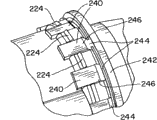
In Figure 13, show a Snap tab 220 in the cross sectional view mode of amplifying.Snap tab 220 is included in the downward-sloping hook 222 that dangles of the end of Snap tab 220.Pedestal 214 is pushed over ring 38 o'clock, and the bevelled guide surface on hook 22 forces Snap tab 220 to upward deflect.In case Snap tab 220, especially its hook 222 is by ring 38, and Snap tab 220 turns back to non-inflection point so, and hook 222 restriction pedestals 214 are not pulled away from basic fuel shut-off valve assemblies 20.Have the termination portion 224 of outside orientation on the outside face of Snap tab 220, its purpose will be described below.
A plurality of lid lugs 240 stretch out from cup-like cover 230, and constitute and be configured to Snap tab 220 basic criss-crosss with pedestal 214.Ring 242 is connected to the end of covering lug 240 by frangible connection 244.Lid lug termination portion 246 is arranged on covers lug 240 outer or terminal parts.In the process of assembling, lid 230 slips over the inner structure that comprises disk 212, and slides along the outward flange of pedestal 214, lid lug 240 and Snap tab 220 criss-crosss.When lid 230 when being in complete insertion position, frangible connection 244 is cracked, is released thereby encircle 242.Encircle the 242 lid lugs 240 that slip over deflect inward then.Encircle 242 slid over cover tabs 240, up to its termination portion 224 on the Snap tab 220.Ring 242 will be fully by covering tab stops 246, and this makes and covers lug 240 deflect inward.In case lid tab stops 246 has been passed through ring 242 fully, then covers lug 240 and will turn back to non-inflection point.At this moment, ring 242 is fixed on and covers between tab stops 246 and the termination portion 224.Like this, lid 230 is attached on the pedestal 214 securely.Maintenance then encircles 242 and is broken if desired, covers 230 to discharge from pedestal 214.Can use have with ring 242 same sizes and shape separate, ring independently, be used for lid 230 is fixed to pedestal 214 again.Also can use the hose clamp of other type etc.Under case of collision, cap assemblies 210 can from valve module 20 remove from, this closes maintenance and seal to prevent that fuel from overflowing.
According to the present invention, housing also can be formed by two parts, thereby basic fuel shut-off valve assemblies 300 (Figure 20) comprises inner shell member 302 and outer shell component 304.Valve member 306 is arranged on the outer shell component 304, and can be similar to previously described valve member 32 herein, perhaps, valve member 306 can be other type and structure, comprises will illustrating subsequently herein.Cap assemblies 308 is connected to outer shell component 304 in final assembly, but showing in the accompanying drawings to throw off therefrom connects.Cap assemblies 308 can be the traditional type with cap, perhaps can be non-cap type, for example the disclosed type in front herein.The present invention is not limited to the cap assemblies of particular type aspect scope.
In first embodiment of two fens sandwich type elements shown in Figure 20 and 21, outer shell component 304 is provided with the flange 314 of guiding radially outward, and inner shell member 302 is provided with annular collar 316 and inwardly is directed into notch portion 310 shoulders 318 from described neck ring 316.In fitting process, flange 314 is arranged in the neck ring 316 and against shoulder 318.Neck ring 316 is folding on flange 314, and there against bending, with by making outer shell component 304 be fixed on the inner shell member 302, as shown in figure 21 between the folding top that flange 314 is squeezed in shoulder 318 and neck ring 316.
In the another kind configuration of two fens sandwich type elements shown in Figure 22 and 23, outwards the annular lip 320 of guiding is arranged on the inner shell member 322, at the outward flange of falred entrance part 324.Inner shell member 322 can be provided with suitable finish coat 325, as the respective surfaces coating 313 on inner shell member 302 that illustrates previously.The neck ring 326 of energy inflection is arranged on the outer shell component 328, has the shoulder 330 of inside guiding at its base portion.In fitting process, flange 320 is arranged in the neck ring 326 and against shoulder 330.Neck ring 326 is folding on flange 320, and there against bending, with by making outer shell component 328 be fixed on the inner shell member 322, as shown in figure 23 between the folding part that flange 320 is squeezed in shoulder 330 and neck ring 326.
Any at the two fraction housing units that just illustrated, in the housing unit shown in the housing unit shown in Figure 20 and 21 or Figure 22 and 23, sealing member 332 can be used in flange 314 or 320 and shoulder 318 or 330 between.
Shown in Figure 22 and 23 and illustrated with respect to it, flange 320 is set on inner shell member 322, and the advantage that the neck ring 326 of energy inflection is set on outer shell component 328 is: do not need distortion, bending and inflection by application member to carry out physics transformation or conversion.What replace is, the uncoated corrosion-resistant steel of outer shell component 328 or other not have the material of coating to be folded and inflection, has reduced the possibility that makes that the coating 325 of inner shell parts 322 suffers damage or ruptures.
Should be appreciated that, therein in the material different with exterior part employing, one of them is coated, in the embodiment of two fens sandwich type elements that another is not coated, can adopt the connection of other type between inner shell member and outer shell component.Deformable neck ring inflection on the flange on another parts on illustrated in the exemplary embodiment parts therein only is a kind of suitable structure that inner shell parts and outer hull parts are fixed together, also can use other fastening layout, for example, but be not limited to, with adhesive agent bonding, welding etc., engage or the like with the physical connection part of described isolation of components or one, interference engagement, screw thread and other interlocking between the parts.
Can use other modification to be used for carrier 54 and baffle door 50 are installed in the inlet 24 of housing 30.As previously described, one or more edge member 72 is received in the groove 44, is used for carrier 54 is fixed on housing 30.According to a further aspect in the invention, housing 340 (Figure 27) is provided with end 341, and this end defines ring edge 342, has annular groove 344 on its outer surface, and this edge 342 is the openings that limit housing inlet 346.Groove 344 can be by shearing, rolling or suppress on the outer surface that is formed on ring edge 342.In preferred manufacture method, can use deep-draw forming (deep draw stamping) method to form housing.Can before being used for forming the break-through (piercing) and extrusion operation at housing and edge 342, on planarization material, suppress groove.Final result goes up at the OD of cylinder (external diameter) by break-through and extrusion operation to form annular groove.Should be noted that housing 340 can be the one-piece construction that is similar to housing 30, perhaps can be other structure, for example the outer shell component 304 of two fraction structures or outer shell component 328.
The carrier 354 that illustrates best at Figure 32 is provided with the ring 356 of wanting slide over rim 342.Ring 356 tilts to its terminal edge 358 a little inwards from its pedestal.Ring 356 is provided with one or more slit 360 that extends inwards from terminal edge 358.Shown in illustrative embodiments in, slit 360 is basic axial orientation on ring 356, but also can be other orientation.When ring 356 was pressed on edge 342, slit 360 allowed the outwardly-bent a little or deflection of the part between slit 360 of ring 356, is convenient to assembling thus.When carrier 354 reached last installation site, terminal edge 358 was received in the groove 344.The orientation of ring 356 bevelled, spring-like has limited that to make that terminal edge 358 shifts out groove 344 needed to extrinsic deflection.Therefore, terminal edge 358 remains positioned in the groove 344 reliably.
In fitting process, baffle door 361 and spring 362 are mounted on the carrier 354, and are mounted on the pivot rod configuration 364 of baffle door 361.Spring end 366,368 engages Carrier arms 370,372, and pivot rod configuration 364 extends through the spiral section 374,376 of spring 362, also extends into Carrier arms 370,372.Spring 362 only is a kind of example, can use the biased element of other type, comprises those elements that illustrate previously herein, but is not limited to this.Sealing member, the sealing member that is used for identical purpose that for example illustrates previously herein is inserted in the ring edge 342, to provide against the sealed engagement of baffle door 361 in the assembly of finishing.In addition, as previously described, sealing member can be installed on the baffle door.Carrier 354 is positioned to encircle 356 and aims at edge 342, and carrier 354 is forced through edge 342, thus encircle 356 along the edge 342 outer surface slides.The diameter that is limited by terminal edge 358 is slightly less than the external diameter at edge 342, thus encircle 356 close on slit 360 and between it the section the assembling process in be forced outwardly deflection.When terminal edge 358 ran into the groove 344 on the outside face at edge 342 and is positioned at wherein, described section resilience inwards of ring 356 was fixed on terminal edge 358 in the groove 344.
The further feature of carrier 354 and structure can be similar to noted earlier herein.For example, carrier 354 can comprise plate-like body 380, and it preferably can be made of metal, and stop collar 356.The leg 382 of main body 380 can be arranged on the circumference of main body 380, and shape, size and structure be adapted to be received in the groove, in for example foregoing herein groove 44, so that carrier 354 is fixed in the housing.In the exemplary embodiment, three legs 382 have been shown; But, also can use more than three legs 382 or be less than three legs 382.Carrier arms 370,372 defines cotyloid cavity 384,386 respectively, is used for keeping pivotally the end of the pivot rod configuration 364 of baffle door 361, as previously described.
Shown in illustrative embodiments in, groove 344 is continuous and around edge 342, and to encircle 356 be continuous substantially except the interruptions that is formed by slit 360.When ring 356 was set at 342 tops, edge, the connection of basic fixed was formed between carrier and the housing by this way.But, should be appreciated that groove 344 also can form a plurality of discontinuous groove sections, ring 356 can be discontinuous, than the circlet section, it is positioned to be used for the engagement groove section.
Just described configuration provides a kind of easy dress difficult maintenance feature of tearing open, wherein, and easier deflection when encircling as required when mounted than dismounting.The dismounting of carrier needs the distortion of carrier, so carrier is fixed on mounted position.Use is used for engaging with housing at the leg 382 of the outer edge of carrier 354, and the ring 356 of carrier 354 engages the edge 342 of housing simultaneously, and the redundancy connection of carrier to housing is provided like this.Therefore, carrier is positioned in the housing securely.
Aforesaid variants and modifications falls within the scope of the invention.Being appreciated that herein that the present invention open and that limit extends to mentions in text and/or the accompanying drawing or two or more all various may the combinations from its conspicuous each feature.All these are different has constituted various possible aspect of the present invention.Described herein embodiment has illustrated and has been used to realize known best way of the present invention, and made those of ordinary skill in the art can realize the present invention.Claims are used to be interpreted as being included in the interior various possibility embodiments of scope that prior art allows.
Various feature of the present invention is stated in appending claims.
Claims (25)
1. fuel shut-off valve assemblies comprises:
Housing, it comprises and defines the inner shell member that is used to be attached to the outlet on the fuel system and the outer shell component that defines inlet that described inlet has the opening that is used for receiving therein the fuel filler mouth;
Baffle door, it is arranged in described outer shell component, can be used to open and close described inlet with respect to described housing motion; And
Described inner shell member and described outer shell component are made from a variety of materials, and are connected to each other.
2. fuel shut-off valve assemblies according to claim 1, one of described housing parts limits flange, another of described housing parts limits neck ring, and described neck ring forms around described flange, is used for described inner shell member and described outer shell component are fixed together.
3. fuel shut-off valve assemblies according to claim 2, described flange are formed on the described inner shell member, and described neck ring is formed on the described outer shell component.
4. fuel shut-off valve assemblies according to claim 2, described flange are formed on the described outer shell component, and described neck ring is formed on the described inner shell member.
5. fuel shut-off valve assemblies according to claim 2, described neck ring limits shoulder, and is provided with sealing member between described shoulder and described flange.
6. fuel shut-off valve assemblies according to claim 1, described inner shell member is included in the finish coat on its inside face.
7. fuel shut-off valve assemblies according to claim 6, described inner shell member limits outward extending flange, and described outer shell component limits around the neck ring of described flange distortion.
8. fuel shut-off valve assemblies according to claim 1, described outer shell component has the erosion resisting material; Has the erosion resisting coating on the described inner shell member.
9. fuel shut-off valve assemblies according to claim 1, described outer shell component limits ring edge, has groove on the outside face of described ring edge, described edge limited described inlet; Carrier has the ring around described edge, and described carrier carries described baffle door pivotally; And described ring has the distal edge that is arranged in the described annular groove.
10. fuel shut-off valve assemblies according to claim 9, described ring tilts to described distal edge inwards from its base portion.
11. fuel shut-off valve assemblies according to claim 10, described ring have at least one slit that extends inwards from described distal edge therein, the described ring of at least a portion is deflectable thus.
12. a fuel shut-off valve assemblies comprises:
Housing, it comprises the outer shell component that is defined for the inner shell member that is attached to the outlet on the fuel system and is defined for the opening that receives the fuel filler mouth therein;
Door, it is movable with respect to described housing on described outer shell component, is used to open and close described opening; And
One in described inner shell member and the described outer shell component limits flange, and another in described inner shell member and the described outer shell component limits neck ring, described neck ring forms around described flange, is used for described inner housing and described body skin are fixed together.
13. fuel shut-off valve assemblies according to claim 12, described inner shell member is formed by different materials with described outer shell component.
14. fuel shut-off valve assemblies according to claim 12, described flange are formed on the described inner shell member, described neck ring is formed on the described outer shell component.
15. fuel shut-off valve assemblies according to claim 12, described flange are formed on the described outer shell component, described neck ring is formed on the described inner shell member.
16. fuel shut-off valve assemblies according to claim 12, described neck ring limits shoulder, and is provided with sealing member between described shoulder and described flange.
17. fuel shut-off valve assemblies according to claim 12, described inner shell member is included in the corrosion-resistant coating on its inside face.
18. fuel shut-off valve assemblies according to claim 17, described inner shell member limits outward extending flange, and described outer shell component limits around the neck ring of described flange distortion.
19. fuel shut-off valve assemblies according to claim 12, described outer shell component limits ring edge, has groove on the outside face of described ring edge, described edge limited described inlet; Carrier has the ring around described edge, the described door of described carrier carrying; And described ring has the distal edge that is arranged in the described groove.
20. fuel shut-off valve assemblies according to claim 19, described ring tilts to described distal edge inwards from its base portion.
21. fuel shut-off valve assemblies according to claim 20, described ring have at least one slit that extends inwards from described distal edge therein, at least a portion of closing on described at least one slit of described ring is deflectable thus.
22. a fuel shut-off valve assemblies comprises:
Housing, it has ring edge, and described ring edge defines the inlet that is used for receiving therein fuel filler nozzle;
Groove, it is at the outside face of described ring edge;
Carrier, it has the ring around described edge;
Described ring has the distal edge that is arranged in the described groove; And
Movable door, it is carried by described carrier, is used for selectively opening and closing described inlet.
23. fuel shut-off valve assemblies according to claim 22, described ring tilts to described distal edge inwards from its base portion.
24. fuel shut-off valve assemblies according to claim 23, described ring have at least one slit that extends inwards from described distal edge therein, at least a portion of closing on described at least one slit of described ring is deflectable thus.
25. fuel shut-off valve assemblies according to claim 22, described groove centers on described edge substantially.
Applications Claiming Priority (2)
| Application Number | Priority Date | Filing Date | Title |
|---|---|---|---|
| US92061507P | 2007-03-29 | 2007-03-29 | |
| US60/920,615 | 2007-03-29 |
Publications (1)
| Publication Number | Publication Date |
|---|---|
| CN101600594A true CN101600594A (en) | 2009-12-09 |
Family
ID=39580076
Family Applications (1)
| Application Number | Title | Priority Date | Filing Date |
|---|---|---|---|
| CNA2008800040088A Pending CN101600594A (en) | 2007-03-29 | 2008-03-25 | The improvement of fuel shut-off valve assemblies and manufacturing thereof and assembly method |
Country Status (6)
| Country | Link |
|---|---|
| EP (2) | EP2125418A2 (en) |
| JP (1) | JP5346007B2 (en) |
| CN (1) | CN101600594A (en) |
| AT (1) | ATE501884T1 (en) |
| DE (1) | DE602008005598D1 (en) |
| WO (1) | WO2008121605A2 (en) |
Cited By (3)
| Publication number | Priority date | Publication date | Assignee | Title |
|---|---|---|---|---|
| CN102994886A (en) * | 2012-09-29 | 2013-03-27 | 铜陵国方水暖科技有限责任公司 | Method for casting valve plate of stop valve |
| CN106163854A (en) * | 2014-01-10 | 2016-11-23 | 伊利诺斯工具制品有限公司 | Filling equipment for oil tank of vehicle |
| CN112250027A (en) * | 2020-11-20 | 2021-01-22 | 芜湖泰科汽车科技有限公司 | Oil gun sealing device with sealing cover plate at end part |
Families Citing this family (6)
| Publication number | Priority date | Publication date | Assignee | Title |
|---|---|---|---|---|
| JP5494291B2 (en) * | 2010-06-30 | 2014-05-14 | 豊田合成株式会社 | Fuel tank opening and closing device |
| IN2014DN08052A (en) | 2012-03-29 | 2015-05-01 | Toyoda Gosei Kk | |
| JP6025421B2 (en) * | 2012-06-29 | 2016-11-16 | 株式会社ニフコ | Valve device |
| DE102012022129A1 (en) * | 2012-11-13 | 2014-05-15 | Kautex Textron Gmbh & Co. Kg | grounding element |
| US9370998B2 (en) * | 2013-09-20 | 2016-06-21 | Honda Motor Co., Ltd. | Fuel filler systems and methods of assembling same |
| DE102016002045B4 (en) | 2015-02-26 | 2022-04-14 | Toyoda Gosei Co., Ltd. | Opening-closing device for a fuel tank |
Family Cites Families (11)
| Publication number | Priority date | Publication date | Assignee | Title |
|---|---|---|---|---|
| FR2588806B1 (en) * | 1985-10-23 | 1990-07-20 | Journee Paul Sa | DEVICE FOR LOCKING A FUEL TANK OF A MOTOR VEHICLE |
| FR2710721B1 (en) * | 1993-09-29 | 1995-11-24 | Journee Paul Sa | Filling head for a filling pipe of a motor vehicle tank. |
| US5732840A (en) | 1995-04-21 | 1998-03-31 | Stant Manufacturing Inc. | Closure assembly for a tank filler neck |
| FR2761934B1 (en) | 1997-04-14 | 1999-05-14 | Journee Paul Sa | FILLING DEVICE FOR A FUEL TANK FOR A MOTOR VEHICLE COMPRISING A FILLING HEAD WITH REINFORCING REINFORCEMENT |
| US6705481B2 (en) * | 1998-03-20 | 2004-03-16 | Temtec Fahrzeutechnick | Actuatable fuel tank closure having guide pipe |
| EP1086842B1 (en) * | 1999-09-22 | 2006-03-08 | Toyoda Gosei Co., Ltd. | Fueling device |
| US6330893B1 (en) | 1999-12-03 | 2001-12-18 | Shelby Enterprises, Inc. | Fuel tank filter neck and method of manufacturing same |
| JP4563572B2 (en) * | 2000-12-01 | 2010-10-13 | 本田技研工業株式会社 | Fuel tank filler tube |
| US6685043B1 (en) * | 2001-09-24 | 2004-02-03 | Common Sense Management, Inc. | Quick fill |
| US7549443B2 (en) * | 2003-12-09 | 2009-06-23 | Illinois Tool Works Inc. | Fuel shut-off valve assembly with associated components and methods of making and assembling the same |
| JP2007008429A (en) * | 2005-07-04 | 2007-01-18 | Asteer Co Ltd | Fuel feed pipe |
-
2008
- 2008-03-25 EP EP08744299A patent/EP2125418A2/en not_active Withdrawn
- 2008-03-25 EP EP10152060A patent/EP2174821B1/en active Active
- 2008-03-25 CN CNA2008800040088A patent/CN101600594A/en active Pending
- 2008-03-25 DE DE602008005598T patent/DE602008005598D1/en active Active
- 2008-03-25 JP JP2010501156A patent/JP5346007B2/en not_active Expired - Fee Related
- 2008-03-25 AT AT10152060T patent/ATE501884T1/en not_active IP Right Cessation
- 2008-03-25 WO PCT/US2008/058105 patent/WO2008121605A2/en active Application Filing
Cited By (3)
| Publication number | Priority date | Publication date | Assignee | Title |
|---|---|---|---|---|
| CN102994886A (en) * | 2012-09-29 | 2013-03-27 | 铜陵国方水暖科技有限责任公司 | Method for casting valve plate of stop valve |
| CN106163854A (en) * | 2014-01-10 | 2016-11-23 | 伊利诺斯工具制品有限公司 | Filling equipment for oil tank of vehicle |
| CN112250027A (en) * | 2020-11-20 | 2021-01-22 | 芜湖泰科汽车科技有限公司 | Oil gun sealing device with sealing cover plate at end part |
Also Published As
| Publication number | Publication date |
|---|---|
| EP2125418A2 (en) | 2009-12-02 |
| EP2174821B1 (en) | 2011-03-16 |
| JP2010522665A (en) | 2010-07-08 |
| DE602008005598D1 (en) | 2011-04-28 |
| WO2008121605A3 (en) | 2009-05-07 |
| ATE501884T1 (en) | 2011-04-15 |
| EP2174821A1 (en) | 2010-04-14 |
| JP5346007B2 (en) | 2013-11-20 |
| WO2008121605A2 (en) | 2008-10-09 |
Similar Documents
| Publication | Publication Date | Title |
|---|---|---|
| CN101600594A (en) | The improvement of fuel shut-off valve assemblies and manufacturing thereof and assembly method | |
| US7617604B2 (en) | Fuel shut-off valve assembly with associated components and methods of making and assembling the same | |
| US8651151B2 (en) | Fuel shut-off valve assemblies and methods of making and assembling the same | |
| US8640745B2 (en) | Tire repair device containing tire cement | |
| US9193229B2 (en) | Tire repair device | |
| CN105813950A (en) | Protective cap for a dispenser, and discharge device for discharging pharmaceutical and/or cosmetical liquids | |
| US11792944B2 (en) | Valve for pressure compensation and/or for emergency venting of a container, in particular of a container of a battery of an electric vehicle, as well as container with such a valve | |
| US10683947B2 (en) | Safety valve and gas cylinder having same | |
| KR100914620B1 (en) | Safety valve for portable gas container | |
| CN210290880U (en) | Fire extinguishing agent container valve component of external pressure storage fire extinguishing system | |
| NZ525124A (en) | Coupling for compressed gas piston driven nailing and fuel cartridge | |
| CN210716168U (en) | Pressure reducing valve | |
| KR20180019343A (en) | Gas container for preventing explosion | |
| AU708908B2 (en) | One-piece aerosol can of aluminium | |
| TWI833008B (en) | Spray cans, actuators and protective components of spray cans | |
| CN210542994U (en) | Container valve | |
| CN210118476U (en) | Rubber sleeve for pneumatic cut-off equipment and pneumatic cut-off equipment | |
| CN219994392U (en) | Hydrogenation valve | |
| CN215045250U (en) | Plastic fuel tank based on anti-static function | |
| JP2538835B2 (en) | Pressure-fillable explosion-proof air valve | |
| CN201057338Y (en) | Safety protective cover of oil pipe joint | |
| EP2942310B1 (en) | Air pressure type tyre repair glue bottle | |
| CN117704128A (en) | Device for sealing connection with an opening of a carrier component | |
| TW202103798A (en) | Aerosol container, actuator and protective member for aerosol container | |
| CN115962415A (en) | Hydrogen storage device valve protection cover and installation method |
Legal Events
| Date | Code | Title | Description |
|---|---|---|---|
| C06 | Publication | ||
| PB01 | Publication | ||
| C10 | Entry into substantive examination | ||
| SE01 | Entry into force of request for substantive examination | ||
| C02 | Deemed withdrawal of patent application after publication (patent law 2001) | ||
| WD01 | Invention patent application deemed withdrawn after publication |
Application publication date: 20091209 |