CN1015736B - Position detector for clapper of non-return valve - Google Patents
Position detector for clapper of non-return valveInfo
- Publication number
- CN1015736B CN1015736B CN88107830A CN88107830A CN1015736B CN 1015736 B CN1015736 B CN 1015736B CN 88107830 A CN88107830 A CN 88107830A CN 88107830 A CN88107830 A CN 88107830A CN 1015736 B CN1015736 B CN 1015736B
- Authority
- CN
- China
- Prior art keywords
- valve
- coil
- valve plate
- plate
- clapper
- Prior art date
- Legal status (The legal status is an assumption and is not a legal conclusion. Google has not performed a legal analysis and makes no representation as to the accuracy of the status listed.)
- Expired
Links
Images
Classifications
-
- F—MECHANICAL ENGINEERING; LIGHTING; HEATING; WEAPONS; BLASTING
- F16—ENGINEERING ELEMENTS AND UNITS; GENERAL MEASURES FOR PRODUCING AND MAINTAINING EFFECTIVE FUNCTIONING OF MACHINES OR INSTALLATIONS; THERMAL INSULATION IN GENERAL
- F16K—VALVES; TAPS; COCKS; ACTUATING-FLOATS; DEVICES FOR VENTING OR AERATING
- F16K15/00—Check valves
- F16K15/02—Check valves with guided rigid valve members
- F16K15/03—Check valves with guided rigid valve members with a hinged closure member or with a pivoted closure member
-
- F—MECHANICAL ENGINEERING; LIGHTING; HEATING; WEAPONS; BLASTING
- F16—ENGINEERING ELEMENTS AND UNITS; GENERAL MEASURES FOR PRODUCING AND MAINTAINING EFFECTIVE FUNCTIONING OF MACHINES OR INSTALLATIONS; THERMAL INSULATION IN GENERAL
- F16K—VALVES; TAPS; COCKS; ACTUATING-FLOATS; DEVICES FOR VENTING OR AERATING
- F16K37/00—Special means in or on valves or other cut-off apparatus for indicating or recording operation thereof, or for enabling an alarm to be given
- F16K37/0025—Electrical or magnetic means
- F16K37/0041—Electrical or magnetic means for measuring valve parameters
-
- Y—GENERAL TAGGING OF NEW TECHNOLOGICAL DEVELOPMENTS; GENERAL TAGGING OF CROSS-SECTIONAL TECHNOLOGIES SPANNING OVER SEVERAL SECTIONS OF THE IPC; TECHNICAL SUBJECTS COVERED BY FORMER USPC CROSS-REFERENCE ART COLLECTIONS [XRACs] AND DIGESTS
- Y10—TECHNICAL SUBJECTS COVERED BY FORMER USPC
- Y10T—TECHNICAL SUBJECTS COVERED BY FORMER US CLASSIFICATION
- Y10T137/00—Fluid handling
- Y10T137/7722—Line condition change responsive valves
- Y10T137/7837—Direct response valves [i.e., check valve type]
- Y10T137/7898—Pivoted valves
- Y10T137/7903—Weight biased
-
- Y—GENERAL TAGGING OF NEW TECHNOLOGICAL DEVELOPMENTS; GENERAL TAGGING OF CROSS-SECTIONAL TECHNOLOGIES SPANNING OVER SEVERAL SECTIONS OF THE IPC; TECHNICAL SUBJECTS COVERED BY FORMER USPC CROSS-REFERENCE ART COLLECTIONS [XRACs] AND DIGESTS
- Y10—TECHNICAL SUBJECTS COVERED BY FORMER USPC
- Y10T—TECHNICAL SUBJECTS COVERED BY FORMER US CLASSIFICATION
- Y10T137/00—Fluid handling
- Y10T137/8158—With indicator, register, recorder, alarm or inspection means
- Y10T137/8225—Position or extent of motion indicator
- Y10T137/8242—Electrical
Abstract
A non-return valve for a steam turbine steam line includes a housing and a clapper swingably mounted in the housing for angular movement between open and closed positions. A metal proximity detector is mounted on the interior surface of the cover for the valve access opening and adjacent the open position of the valve. Movement of the clapper away from its open position results in a signal providing an indication that the valve clapper is away from its open position.
Description
The present invention relates to a kind of one-way valve, mainly be used in the discharge pipe of steam turbine vapour system, especially for the position of indication one-way valve valve plate and the monitor unit of situation.
In the steam pipework that the present invention is used in especially with steam turbine links to each other, this steam turbine is generally used for driving Generator Set to produce powerful electric power.Problem in this steam turbine-gen-set is: when equipment through in a few years use, after particularly periodically using and/or moving, the accident that water or cold steam enter steam turbine can appear.Fault in the heat circulating equipment can cause into water and cold steam in very high place, and these places comprise it being the steam introduction pipe line, and heat-heating steam intake pipeline again is cold-heating steam pipeline again, exhaust line, the waste pipe place of steam tight system and steam turbine.Enter the water of generator or cold steam except meeting causes device damage and mechanical failure, also can seriously influence the life-span of equipment.
Water entering accident is so serious, so that American Society of Mechanical Engineers (ASME) has been set up a steam turbine damage by water ATSC Advanced Television Systems Committee, and has concluded the Power Plant Design standard that prevents damage by water in American National Standards Institute/American Society of Mechanical Engineers TDJ-1-1985 number.Recently, made research , And with regard to power generating equipment actual operating state (EPRI of Electric Power Research Institute) and proposed to announce a report that this report is CS-4285 by research institute, exercise question is " detection of steam turbine water inlet, the 3rd phase, a live demonstration ".These researchs are emphasized and will the system that be used for steam turbine be monitored, in case the such serious problems of water inlet take place.
At present, water entering accident mainly occurs in discharge pipe, heater and cold-heat in the pipeline again.For preventing into water or be to reduce water inlet at least that the someone proposes on the discharge pipe of steam turbine one-way valve to be installed.This valve can allow steam to flow to a direction, and it prevents, is to stop the negative side to be flowed at least.The use of this valve is known, and it does not constitute some of the present invention.
Serious problems of one-way valve are that it can lose efficacy in the rugged environment of the vapour system that links to each other with steam turbine.Valve in these steam pipe lines and the container, static or nonstatic member without any the surperficial mark of breakage to situation under may damage.With regard to one-way valve, damage can comprise that valve plate wearing and tearing can not close, and the valve plate high vibration causes getting loose, and is pushed downwards to heater.So not only damaged valve itself, and this damage may not realized in long time that last water entering accident may cause main steam turbine to break down.
Can determine the prober of valve position to find out in 618,824 the example from U. S. application US.4.The prober of this application is placed in outside the valve body, and the interference of housing hinders the detection of valve position to a certain extent, and the prober in the valve body may be exposed in the interior liquid of valve, and this liquid usually can corrode or the tamper detection device.
Therefore whether normally, the purpose of this invention is to provide and a kind ofly be used to survey one-way valve, or miscellaneous equipment work device, this device to liquid in the valve accurately and responsive.
The objective of the invention is to realize by such one-way valve.This valve comprises a valve body and a valve plate, and valve body has one to detect opening, and opening is by a covering palte seal that is contained in above it, and valve plate is contained in the valve body, and can swing between its opening and closing position.It is characterized in that in valve body on the internal surface of cover plate, a metal is equipped with near prober in the enable possition of contiguous valve plate, it comprises an electroresponse device, and when valve plate during not in its enable possition, prober can provide an electrical signal that changes.
The electroresponse device preferably comprises a coil at least, and this coil is normally circular, and preferably extends along the internal surface that detects cover plate.In one embodiment of the invention, the electroresponse device comprises a single coil, and it is circular, and is contained in the ceramic cavity, and ceramic cavity is close on the internal surface of valve opening cover plate.
For example to the description of most preferred embodiment of the present invention, the present invention may be better understood by following (referring to accompanying drawing), wherein:
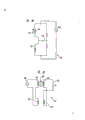
Fig. 1 is a sectional drawing, represents that one is contained in the one-way valve on the steam pipework and is equipped with of the present invention near prober and monitor unit;
Fig. 2 is the part perspective view of prober of the present invention;
Fig. 3 is the perspective view similar to Fig. 2, represents the part of the prober of another kind of form of the present invention;
Fig. 4 represents to be used for the circuit diagram of a kind of circuit of the present invention;
Fig. 5 represents to be used for the circuit diagram of another kind of circuit of the present invention.
Fig. 1 represents an one-way valve 10, and it is suitable for being installed in the steam pipework 12 that links to each other with the steam turbine (not shown).The normal flow direction of steam is as shown in arrow 14 in the steam pipework 12.Valve generally includes a valve body 15 and a valve plate 16 with regard to its mechanical property.Valve plate 16 is installed in the valve body 15 swingably, and it can shown in enable possition shown in solid line among Fig. 1 and the dotted line be to close between the position to swing around the axis of mount pin 18.When valve plate 16 was positioned at its closed position, it sealed the gap 20 of valve 10, thereby can prevent that steam from flowing along the opposite direction of arrow 14.
Those skilled in the art as the prior art field are known, and in the present invention, the flowing of 16 pairs of media of valve plate of valve 10, gravity and/or extraneous closing function react.Steam pushes up valve plate 16 to its enable possition along the energy of flow of arrow 14 directions, or adds gravity and/or extraneous closing function along arrow 14 reciprocal flowing, and will make valve plate 16 around sub 18 forwarding its closed position to slightly, as shown in phantom in Figure 1.In addition, valve, for example valve 10 can be equipped with known Effector, and according to intrasystem condition, this Effector operably links to each other with valve plate 16 to stop valve plate 16 around pin 18 and the rotation between closed position and enable possition.This device is passable, as reacting when obtaining the signal that will intake, is causing in the pipeline 12 cut-off valve 10 before the reverse flow owing to water entering accident.
Valve body 15 has an import 22, and import 22 is by cover plate 24 sealings, and as shown in Figure 1, cover plate 24 is fixed on the valve body 15 by screw 26 or other similar traditional approach usually.
One metal detector 27 comprises that an electroresponse device 28 is contained in contiguous valve plate 16 open position in the valve body 15.When valve plate 16 during not in its enable possition, electroresponse device 28 can provide an electrical signal that changes, and this will describe in detail in the back.
A kind of optimised form as shown in Figure 2, electroresponse device 28 comprise an annular search coil 32 that is contained in the ring-shaped pottery cavity 34.Fig. 2 is the partial view of electroresponse device, and in fact it is circular, and by assembling set, is close to such as screw 36 on the surface 30 of cover plate 24, as shown in Figure 2.Therefore, cavity 34 provides a bearing, so that coil 32 and valve 10 insulation.
Prober 27 also comprises electric lead 38, and condition in the valve body 15 is changed the circuitry 40 that responds, and the device that a visible signal or electrical signal are provided according to the electrical signal of system's 40 outputs.
Among the present invention used optimal circuit as shown in Figure 4, in Fig. 4, coil 32 is positioned at the position of circuit diagram left hand inferior horn.Circuit shown in Figure 4 is traditional induction Hui Sideng (Weatstone) bridge circuit, and this circuit comprises a coil 44 and an ac signal which 46.In this circuit, adjust fuse 48 movably up to voltage V by electric bridge 50
0Equal zero or be approximately zero.The inductance of coil 32 will change with the change in location of valve plate 16, thereby causes the voltage of electric bridge 50 to change, and measures this voltage, can express moving of valve plate 16.
Another can be used for circuit of the present invention as shown in Figure 5: the circuit relationships in No. 3,017,621, this circuit and the U. S. Patent is similar, in Fig. 5 with reference number 40 ' represent.Circuit 40 ' be a linear change differential transformer type circuit, And comprise a primary air 32 ' and a level coil 32 ", two coils must be contained in the valve body.Circuit 40 ' a comprise ac power supply 46 ', Reference coil 44 ' and 44 ", and adjustable fuse 48 ', this fuse 48 ' circuit is carried out initial adjustment is so that at 50 of circuit ' section generation one initial voltage V
0, part of path 50 ' on voltage V
0Will be with the changing of metal valve plate 16 near situation, the position of metal valve plate 16 make coil 32 ' and 32 " between inductive change.
Circuit shown in Figure 5 is used for structure shown in Figure 3, wherein coil by ceramic cavity 34 Ge Kai And by cavity 34 ' make coil and cover plate 24 insulation.Cavity 34 ' by have screw 36 ' and screw device be installed on the cover plate 24, as shown in Figure 3.Cavity 34 ' be used to support coil 32 ' and 32 " And separates two coils mutually, but cavity 34 ' similar to cavity 34.
Valve plate 16 leaves its enable possition, will cause coil 32 in Fig. 4 circuit and the coil 32 in Fig. 5 circuit ', 32 " in inductance change.No matter the sort of situation all can make voltage V
0The corresponding variation taken place, and expression valve plate 16 has left its enable possition in fact.Therefore, device of the present invention can be used for monitoring the implementation status of the shutdown signal that mails to valve closure body, because the action of valve closure body causes valve plate 16 to leave its enable possition.In addition, if valve plate, so just has a constant this situation that lacks valve plate of signal indication not in the enable possition.If valve plate is in normal working, electrical signal does not just change.
In optimised form, referring to Fig. 2 and 3, coil 32 or 32 ' and 32 " normally Yuan Xing De And extends along the internal surface of cover plate 24.In addition, no matter in the sort of embodiment, coil all be contained in a ceramic cavity 34 or 34 ' in, this cavity 34 or 34 ' be close on the surface 30.This mounting type provides a reliable reference point for circuitry.Coil 32 or 32 ', 32 " preferably make, have one deck high-temperature ceramic coating on the copper wire by copper wire, during coil 32 or 32 ' 32 " is bonded in the groove 52 of structure shown in Figure 2 or the groove 52 of structure shown in Figure 3 ".Groove 32 and 32 ' 32 " is to be made of relative ceramic ring 34a and 34b in the structure of Fig. 2, and is made of ceramic ring 34a ' and 34b ' in the structure of Fig. 3.Ring 34a and 34b and ring 34a ' are in the same place with the available high temperature Sa Ersen of 34b ' (Saureisen) adhesives.Insulating material is preferably selected the material of long and better mechanical property of those life-spans for use, and these materials all are existing, can select the conduit of valve inside conductor directed outward the conduit of minor diameter for use, and this conduit is also known, and its And does not belong to the present invention.
In the middle of using, when valve plate 16 is in the safe opening position, shown in solid line among Fig. 1, to the circuitry shown in the Figure 4 and 5 with fuse 48 or 48 ' regulate, the signal that makes system show be zero or signal value very little.Do the time spent when valve is subjected to external force, valve plate will leave cover plate 24 and swing to its closed position.Cause that thus the imbalance in the circuit can detect at an easy rate from circuitry.Whether this detection process can periodically carry out, so that determine at the effect lower valve plate of external force suitably and the response of valve plate.Therefore, device of the present invention can be used as an early stage accident detection device, so that survey under the effect of vibration and impact, whether valve plate can break down.In addition, if valve plate is lost, this will produce nonvolatil circuit imbalance in circuitry, and this phenomenon can detect immediately, thereby prevents that steam turbine from damaging.
Valve of the present invention can be used for checking: the starter of letter is closed in (1) response, (2) revise mechanical coupling between outer manipulator and the valve rod, freely the rotating of (3) valve rod, (4) are with the rotation of valve rod, whether the valve plate on the valve rod gets loose, and whether (5) valve plate is determined to be installed on the valve rod.
Claims (2)
1, one one-way valve, it comprises a valve body (15), valve body (15) has an opening (22), one cover plate (24) is used to seal opening (22), one is installed in the valve plate (16) in the valve body (15), valve plate (16) can be swung between its enable possition and closed position, it is characterized in that having a metal that comprises electroresponse device (28) near prober (27), be installed on the internal surface of the described cover plate (24) in the valve body (15), the enable possition of contiguous valve plate (16), when described valve plate (16) during not in its enable possition, the electroresponse device will provide an electrical signal that changes, and described electroresponse device (28) comprises the coil (32) that the above-mentioned enable possition of vicinity is provided with at least, and this coil (32) is contained in the ceramic cavity (34b), and cavity (34b) is close to and is installed on the described cover plate (24).
2, valve as claimed in claim 1 is characterized in that described electroresponse device is circular and comprises a coil (32) at least.
Applications Claiming Priority (2)
| Application Number | Priority Date | Filing Date | Title |
|---|---|---|---|
| US121,813 | 1987-11-16 | ||
| US07/121,813 US4777979A (en) | 1987-11-16 | 1987-11-16 | Position detector for clapper of non-return valve |
Publications (2)
| Publication Number | Publication Date |
|---|---|
| CN1042767A CN1042767A (en) | 1990-06-06 |
| CN1015736B true CN1015736B (en) | 1992-03-04 |
Family
ID=22398967
Family Applications (1)
| Application Number | Title | Priority Date | Filing Date |
|---|---|---|---|
| CN88107830A Expired CN1015736B (en) | 1987-11-16 | 1988-11-15 | Position detector for clapper of non-return valve |
Country Status (7)
| Country | Link |
|---|---|
| US (1) | US4777979A (en) |
| JP (1) | JPH01155005A (en) |
| KR (1) | KR890008496A (en) |
| CN (1) | CN1015736B (en) |
| CA (1) | CA1297378C (en) |
| ES (1) | ES2011895A6 (en) |
| IT (1) | IT1225438B (en) |
Families Citing this family (35)
| Publication number | Priority date | Publication date | Assignee | Title |
|---|---|---|---|---|
| US5154080A (en) * | 1986-10-29 | 1992-10-13 | Westinghouse Electric Corp. | Integrated check valve testing system |
| JPH02161360A (en) * | 1988-06-06 | 1990-06-21 | Daido Metal Co Ltd | Electric galvanometer |
| US5008841B1 (en) * | 1989-07-28 | 1995-09-19 | Liberty Technologies Inc | Non-invasive system and method for inspection of valves |
| US5086273A (en) * | 1990-04-20 | 1992-02-04 | Liberty Technology Center, Inc. | A.C. electromagnetic system for determining position of an encased movable electrically conductive element |
| US5140263A (en) * | 1990-04-20 | 1992-08-18 | Liberty Technology Center, Inc. | System for determining position of an internal, movable conductive element |
| US5193568A (en) * | 1991-06-20 | 1993-03-16 | Martin Marietta Energy Systems, Inc. | Noninvasive valve monitor using alternating electromagnetic field |
| US5228342A (en) * | 1991-07-26 | 1993-07-20 | Westinghouse Electric Corp. | Ultrasonic position sensor and method |
| US5113901A (en) * | 1991-09-09 | 1992-05-19 | Young Jack W | Sewer relief valve |
| US5471138A (en) * | 1993-02-23 | 1995-11-28 | Glass, Iii; Samuel W. | Inductive valve motion sensor for positioning outside the body of the valve |
| US5938187A (en) * | 1997-04-18 | 1999-08-17 | Gerber Systems Corporation | Media feed apparatus for an imaging device |
| US6042101A (en) * | 1997-06-03 | 2000-03-28 | Gerber Systems Corporation | Automated media transport device and method of using the same |
| EP0971100B1 (en) * | 1998-07-07 | 2003-09-03 | DaimlerChrysler AG | Magnetic protection for an electromagnetic valve actuator |
| US6308723B1 (en) | 1998-11-18 | 2001-10-30 | Alliedsignal, Inc. | Piezo-resistive position indicator |
| DE19939497C2 (en) * | 1999-08-20 | 2001-09-27 | Samson Ag | Drive of a control valve with sensing unit for valve position detection |
| US6742539B2 (en) | 2000-05-24 | 2004-06-01 | Innovative Controls | Co-axial control valve |
| CN2523953Y (en) * | 2002-02-11 | 2002-12-04 | 王歆 | Flying and water entering protector for steam turbine |
| US7634328B2 (en) * | 2004-01-20 | 2009-12-15 | Masoud Medizade | Method, system and computer program product for monitoring and optimizing fluid extraction from geologic strata |
| US7429803B2 (en) * | 2005-08-01 | 2008-09-30 | Rufus Davis | Sewer line power generating system |
| DE102008011273A1 (en) * | 2008-02-26 | 2009-08-27 | Wilo Ag | Check valve with displacement sensor |
| CN104903638B (en) * | 2012-11-30 | 2018-03-27 | 澎巍股份有限责任公司 | Continuous magnetic movement position indicator |
| CH707857A1 (en) * | 2013-04-02 | 2014-10-15 | Medela Holding Ag | Device with a flow channel. |
| CA2830404C (en) * | 2013-10-21 | 2019-01-22 | Gabe Coscarella | Low profile overbalanced backwater valve |
| US10914412B2 (en) | 2018-06-28 | 2021-02-09 | Watts Regulator Co. | Backflow prevention assembly having a variable lay-length and orientation |
| WO2020117483A1 (en) * | 2018-12-04 | 2020-06-11 | Flowserve Management Company | Continuous tilt angle indicator for a swing or tilting disk check valve |
| US11214953B2 (en) | 2019-02-19 | 2022-01-04 | Gabe Coscarella | Locked backwater valve |
| EP3705866B1 (en) | 2019-03-08 | 2023-09-20 | WATTS INDUSTRIES ITALIA S.r.l. | Differential pressure sensor with magnetic dial |
| US11795666B2 (en) | 2019-05-08 | 2023-10-24 | Watts Regulator Co. | Wireless communication system within a mechanical room |
| US11815424B2 (en) | 2019-05-08 | 2023-11-14 | Watts Regulator Co. | Backflow prevention system test cock with a fluid sensor |
| EP3748210B1 (en) * | 2019-06-07 | 2023-01-04 | Focus-On V.O.F. | Blocking structure for a fluid |
| EP3835494A1 (en) * | 2019-12-10 | 2021-06-16 | Watts Regulator Co. | System for monitoring backflow preventer condition |
| US11585076B2 (en) | 2020-01-24 | 2023-02-21 | Watts Regulator Co. | Apparatus and method for valve cartridge extraction |
| US11719352B2 (en) | 2020-08-17 | 2023-08-08 | Watts Regulator Co. | Check cover assemblies for backflow prevention assemblies with integrated test cock protection shroud |
| US11773992B2 (en) | 2020-08-17 | 2023-10-03 | Watts Regulator Co. | Backflow prevention assembly with a linkage |
| US11739507B2 (en) | 2020-12-09 | 2023-08-29 | Watts Regulator Co. | Test cock with integrated extraction tool |
| USD1021000S1 (en) | 2021-08-17 | 2024-04-02 | Watts Regulator Co. | Valve assembly and body for same |
Family Cites Families (14)
| Publication number | Priority date | Publication date | Assignee | Title |
|---|---|---|---|---|
| US3017621A (en) * | 1956-12-31 | 1962-01-16 | Martin Marietta Corp | Proximity limit position detector |
| US3859619A (en) * | 1972-07-11 | 1975-01-07 | Nippon Denso Co | Valve operation detecting device |
| US3857277A (en) * | 1972-12-29 | 1974-12-31 | Laval Turbine | Flow indicator |
| US3896280A (en) * | 1974-03-13 | 1975-07-22 | Us Army | Valve position indicator |
| US4316145A (en) * | 1976-10-01 | 1982-02-16 | Electro-Mechanical Products | Fluid pressure actuator with proximity position sensor |
| DE2839774A1 (en) * | 1978-09-13 | 1980-03-27 | Yoram Prof Dr Med Palti | DEVICE FOR ADJUSTING THE FLOW SECTION OF A VALVE |
| JPS5676767A (en) * | 1979-11-26 | 1981-06-24 | Hitachi Ltd | Detecting method for abnormality in swing-type nonreturn valve |
| GB2095407B (en) * | 1981-03-24 | 1984-10-17 | Ferranti Ltd | Valve status indicator |
| DE3265540D1 (en) * | 1981-04-15 | 1985-09-26 | Ici Plc | Determining valve position |
| FR2531176A1 (en) * | 1982-07-29 | 1984-02-03 | Framatome Sa | DEVICE FOR DETECTING THE OPERATION OF A VALVE |
| KR850001259B1 (en) * | 1983-09-24 | 1985-08-26 | 주식회사 일광 | Detector of gas leakage |
| FR2559305B1 (en) * | 1984-02-08 | 1986-10-17 | Telemecanique Electrique | ANALOGUE MANIPULATOR |
| US4618824A (en) * | 1984-07-16 | 1986-10-21 | Westinghouse Electric Corp. | Method of testing the operability of check valves |
| JPS62247103A (en) * | 1986-04-21 | 1987-10-28 | Hitachi Ltd | Valve close operation test control device of bleed air check valve |
-
1987
- 1987-11-16 US US07/121,813 patent/US4777979A/en not_active Expired - Fee Related
-
1988
- 1988-11-09 IT IT8841708A patent/IT1225438B/en active
- 1988-11-14 JP JP63285953A patent/JPH01155005A/en active Granted
- 1988-11-14 CA CA000583047A patent/CA1297378C/en not_active Expired - Lifetime
- 1988-11-15 ES ES8803467A patent/ES2011895A6/en not_active Expired - Lifetime
- 1988-11-15 CN CN88107830A patent/CN1015736B/en not_active Expired
- 1988-11-16 KR KR1019880015080A patent/KR890008496A/en not_active Application Discontinuation
Also Published As
| Publication number | Publication date |
|---|---|
| US4777979A (en) | 1988-10-18 |
| CN1042767A (en) | 1990-06-06 |
| JPH0415363B2 (en) | 1992-03-17 |
| ES2011895A6 (en) | 1990-02-16 |
| JPH01155005A (en) | 1989-06-16 |
| KR890008496A (en) | 1989-07-10 |
| CA1297378C (en) | 1992-03-17 |
| IT8841708A0 (en) | 1988-11-09 |
| IT1225438B (en) | 1990-11-13 |
Similar Documents
| Publication | Publication Date | Title |
|---|---|---|
| CN1015736B (en) | Position detector for clapper of non-return valve | |
| CN106990353A (en) | A kind of relay fault detecting circuit and the relay with the circuit | |
| FI871047A (en) | KULVENTIL. | |
| CN108594149A (en) | A kind of portable fault detector test device | |
| CN108871491A (en) | A kind of bushing shell for transformer intelligence oil level gauge | |
| CN104806375B (en) | A kind of two-stroke cross-head diesel engine stuffing box device | |
| CN105655100A (en) | 10kV-level epoxy resin cast dry-transformer | |
| CN111477497A (en) | Intelligent double-floating-ball gas relay and monitoring system | |
| US4609796A (en) | Liquid level sensing switch | |
| CN102903405B (en) | The main air supply system of a kind of high temperature gas cooled reactor helium circulator balanced seal | |
| CN207914330U (en) | A kind of roughing mill and its temperature control system | |
| CN205941737U (en) | Radiator fan's fault detection device and heat abstractor | |
| CN208999067U (en) | A kind of generator sealing bearing bush experimental rig | |
| CN208109160U (en) | A kind of generator sealing bearing bush simulated experiment rack | |
| US3155956A (en) | Bearing failure predicting device | |
| CN215522886U (en) | Natural gas pressure regulating station for supplying gas to supercritical circulating fluidized bed boiler | |
| CN208982333U (en) | Anti-surge protection device for centrifugal compressor units | |
| EP0572715A1 (en) | Check valve testing method | |
| CN206439471U (en) | Actuator, electric control valve and temperature-decreased pressure reducer | |
| CN208621275U (en) | The stage body temperature of electric vibration table measures and overheat protecting system | |
| CN113266764A (en) | Natural gas pressure regulating station and method for supercritical circulating fluidized bed boiler gas supply | |
| CN208012762U (en) | A kind of online infrared temperature measurement apparatus mounting structure | |
| CN2264365Y (en) | Pipeline liquid level signalling device | |
| CN212539248U (en) | Wireless sensing device based on temperature oil gas pressure measurement | |
| CN208268791U (en) | A kind of seal for pipe joints intelligent monitoring and controlling device |
Legal Events
| Date | Code | Title | Description |
|---|---|---|---|
| C06 | Publication | ||
| PB01 | Publication | ||
| C10 | Entry into substantive examination | ||
| SE01 | Entry into force of request for substantive examination | ||
| C13 | Decision | ||
| GR02 | Examined patent application | ||
| C14 | Grant of patent or utility model | ||
| GR01 | Patent grant | ||
| C19 | Lapse of patent right due to non-payment of the annual fee | ||
| CF01 | Termination of patent right due to non-payment of annual fee |