CN101563610A - Magnetic sensor device with suppression of spurious signal components - Google Patents
Magnetic sensor device with suppression of spurious signal components Download PDFInfo
- Publication number
- CN101563610A CN101563610A CNA2007800467657A CN200780046765A CN101563610A CN 101563610 A CN101563610 A CN 101563610A CN A2007800467657 A CNA2007800467657 A CN A2007800467657A CN 200780046765 A CN200780046765 A CN 200780046765A CN 101563610 A CN101563610 A CN 101563610A
- Authority
- CN
- China
- Prior art keywords
- magnetic
- signal
- sensor device
- magnetic sensor
- frequency
- Prior art date
- Legal status (The legal status is an assumption and is not a legal conclusion. Google has not performed a legal analysis and makes no representation as to the accuracy of the status listed.)
- Pending
Links
Images


Classifications
-
- G—PHYSICS
- G01—MEASURING; TESTING
- G01R—MEASURING ELECTRIC VARIABLES; MEASURING MAGNETIC VARIABLES
- G01R33/00—Arrangements or instruments for measuring magnetic variables
- G01R33/02—Measuring direction or magnitude of magnetic fields or magnetic flux
- G01R33/06—Measuring direction or magnitude of magnetic fields or magnetic flux using galvano-magnetic devices
- G01R33/09—Magnetoresistive devices
- G01R33/093—Magnetoresistive devices using multilayer structures, e.g. giant magnetoresistance sensors
-
- B—PERFORMING OPERATIONS; TRANSPORTING
- B82—NANOTECHNOLOGY
- B82Y—SPECIFIC USES OR APPLICATIONS OF NANOSTRUCTURES; MEASUREMENT OR ANALYSIS OF NANOSTRUCTURES; MANUFACTURE OR TREATMENT OF NANOSTRUCTURES
- B82Y25/00—Nanomagnetism, e.g. magnetoimpedance, anisotropic magnetoresistance, giant magnetoresistance or tunneling magnetoresistance
-
- G—PHYSICS
- G01—MEASURING; TESTING
- G01R—MEASURING ELECTRIC VARIABLES; MEASURING MAGNETIC VARIABLES
- G01R33/00—Arrangements or instruments for measuring magnetic variables
- G01R33/12—Measuring magnetic properties of articles or specimens of solids or fluids
- G01R33/1269—Measuring magnetic properties of articles or specimens of solids or fluids of molecules labeled with magnetic beads
Abstract
The invention relates to a magnetic sensor device for the determination of magnetized particles (3) which comprises a magnetic field generator (1, 1') (e.g. a conductor wire) that is driven with an excitation current (II) of a first frequency (f1), and a magnetic sensor element (2) (e.g. a GMR resistance), that is driven with a sensor current (I2) of a second frequency (f2) for generating measurement signals (UGMR). A preprocessed signal (uf) is then generated from the measurement signal (UGMR) that comprises a predetermined frequency (Delta f), and an evaluation unit (10) separates from this preprocessed signal a spurious component that does not depend on the presence of magnetized particles (3) in the sample chamber. The spurious component (UQ) may particularly be caused by self-magnetization (H2) of the magnetic sensor element (2) in combination with parasitic (capacitive or inductive) cross-talk. Furthermore, an unknown, variable phase-shift (fSP) in the preprocessed signal (uf) may be determined by varying the ratio between the spurious component and a particle-dependent target component. This variation may for example be achieved if, in an optimization stage (OS), the excitation current (I1) is conducted through a bypass resistor (R, R') and/or if an additional capacitor is introduced between the magnetic field generator and the magnetic sensor element. The determined phase shift can then be used to adjust the phase of a demodulation signal (udem) such that the spurious component is suppressed.
Description
Technical field
The present invention relates to a kind of method and magnetic sensor device that is used for the magnetized particles of test sample chamber (sample chamber).In addition, the invention still further relates to the use of such device.
Background technology
According to WO 2005/010543A1 and WO 2005/010542A2, known a kind of micro fluidic biosensor that for example can be used for is to detect the magnetic sensor device with (biological example) molecule of marked by magnetic bead.The micro sensing device is provided with sensor cell array, and sensor cell array comprises the giant magnetoresistance device (GMR) that is used to generate the electric wire in magnetic field and is used to detect the stray magnetic field that is generated by magnetic bead.Near so magnetic bead quantity the resistance indication sensor unit of GMR.
The problem of the biology sensor of mentioned kind is that measuring-signal comprises and the irrelevant component of the existence of magnetized particles, thereby can damage the degree of accuracy of measurement result.
Based on this situation, target of the present invention provides the device that is used for improving by magnetic sensor device measuring accuracy.
Summary of the invention
This target of the present invention is by according to the magnetic sensor device of claim 1, be used for realizing according to the method for claim 2 and according to making of claim 12.Dependent claims discloses preferred embodiment.
Magnetic sensor device according to the present invention is used for detection of magnetized particles, for example detects the magnetic bead of mark in addition of the target molecule in the sample.It comprises with lower member:
-sample chamber can provide particle to be detected in this sample chamber.This sample chamber is cavity or be full of the chamber of certain material (as gelinite) that can absorb sample typically; It can be the chamber of beginning to speak, closing the chamber or be connected to other chamber by the fluid interface channel.
-at least one magnetic field generator, it is driven by the exciting current that comprises first frequency, and (somewhere at least) generates magnetic excitation field in the sample chamber to be used for.Here and hereinafter, so-called " signal comprises certain frequency " should be that the fourier spectrum to described signal is the simple expression of non-zero for described frequency.Magnetic field generator can specifically be realized by at least one lead on the microelectronic sensor substrate.
-at least one associated magnetic sensor element, it is driven to be used to generate measuring-signal by the sensor current that comprises second frequency.The magnetic sensing element is being associated with above-mentioned magnetic field generator on the following meaning: it is within the coverage that is caused by the magnetic pumping place of described generator.The magnetic sensing element can specifically comprise coil, Hall element, plane Hall element, fluxgate sensor, SQUIDS (superconducting quantum interference device), magnetic resonance sensors, magnetoresistive transducer or magnetoresistive transducer, especially GMR, TMR (tunnel magnetoresistive) or the AMR (anisotropic magnetoresistive) of kind described in WO 2005/010543A1 or WO 2005/010542A2.
Exciting current and sensor current typically by certain power supply unit for example constant current source provide.
-signal processing circuit, be used for from measuring-signal generate comprise at least one preset frequency through pretreated signal.Signal processing circuit will typically comprise one or more bandpass filter or be used for implementing selecting from the entire spectrum of measuring-signal described functional demodulating equipment of characteristic frequency that the frequency of wherein said selection relates to first and second frequencies.By such frequency filtering, can pick out and the irrelevant a large amount of interference of the existence of magnetic particle.In addition, signal processing circuit typically comprises amplifier.
-evaluation unit is used for from separate at least one " spurious component (spurious component) " through pretreated signal, and is irrelevant according to the existence of the magnetized particles in described spurious component of definition and the sample chamber.Evaluation unit can be realized together with appropriate software by specialized hardware and/or by certain microcomputer system.It preferably is coupled to the magnetic sensing element to be used to receive measuring-signal by electric wire." separation " of spurious component from measuring-signal can mean specifically that it is suppressed by evaluation unit, thereby the output of evaluation unit is the measuring-signal of not being with spurious component.Yet separation can also mean that spurious component is isolated or determine and be used for other purposes.
Described magnetic sensor device has obtained the high correlation of the magnetized particles amount (being interested value) in its output and the sample chamber by following steps: (i) be respectively excitation and sensor current and use first and second frequencies, (ii) from the frequency spectrum of measuring-signal, select to have preset frequency through pretreated signal, and (iii) separate in pretreated signal and the irrelevant spurious component of existence magnetized particles.Last treatment step especially provides additional degree of accuracy to improve, and reason is that it has solved the following fact: the selection of special frequency band may be not enough to the component relevant with particle of isolation measurement signal and the interference that has nothing to do with particle.
The present invention comprises also and a kind ofly determines the method for the particle in the sample chamber by means of magnetic sensor device (being specially above-described device) that wherein this method may further comprise the steps:
-utilize the magnetic field generator that drives by the exciting current that comprises first frequency in the sample chamber, to generate magnetic excitation field.
-utilize the magnetic sensing element that drives by the sensor current that comprises second frequency to generate measuring-signal.
-utilize signal processing circuit to generate through pretreated signal from measuring-signal, wherein saidly comprise at least one preset frequency through pretreated signal.
-utilize evaluation unit from through pretreated signal, separating spurious component, the existence of the magnetized particles in described spurious component and the sample chamber is irrelevant.
This method comprises the step that formation can be carried out with the magnetic sensor device of top description kind with general type.Therefore, understand details, advantage and improved more information with reference to the description of front about this method.
Hereinafter, the preferred embodiments of the present invention have been described, they relate to the magnetic sensor device that proposed and method the two.
Thereby, be included in preset frequency in pretreated signal and can specifically be poor (if described electric current comprises some first and second such frequencies, then the difference on the frequency of respective number can be used as preset frequency) between the second frequency of the first frequency of exciting current and sensor current.As analyze demonstration, the difference between first and second frequencies relates to the component of the measuring-signal of the existence of magnetized particles in the reflection sample chamber.
For some specific design of magnetic sensor device, can be analyzed and through the composition of pretreated signal owing to specific physical influence.Under such situation, comprise " target component " through pretreated signal, it is that described magnetic reaction field is encouraged by magnetic excitation field owing to the magnetic reaction field of particle in the sample chamber is caused; In addition, comprise spurious component through pretreated signal, this spurious component has the frequency identical with described target component but has definite phase shift with respect to target component.Such phase shift is introduced by some physical influence or by the existence of some electric component in the magnetic sensor device typically.Phase shift can specifically have about 90 ° value, and this allows by using the restituted signal with the target component homophase to come the demodulation measuring-signal to cancel spurious component.
In another specific embodiment of the present invention, this embodiment preferably realizes in conjunction with an above mentioned embodiment, and spurious component is by the self-magnetization of magnetic sensing element and the capacitive character between combined magnetic field generator and the magnetic sensing element and/or inductive parasitic crosstalk and generate.Since self-magnetization relevant with (sensor current) second frequency and owing to parasitic crosstalk relevant with (exciting current) first frequency, these two kinds of effects generate the spurious component of measuring-signals, and it has and the identical frequency of target component of being correlated with particle that combination produced by magnetic reaction field (first frequency) and sensor current (second frequency).Therefore such spurious component can not be suppressed by simple frequency filtering, and requires the meticulousr processing in the evaluation unit.As explaining with reference to accompanying drawing in more detail, this processing can be based on (fixing) phase shift that exists between spurious component and the target component.
What mentioned is: if spurious component and have fixing phase differential between the interested target component, then separation/the inhibition of spurious component can easily obtain by suitable restituted signal.In fact, however this straightforward procedure owing to can comprise this true being obstructed of (having in the component of preset frequency) variable unknown phase shift through pretreated signal.Such variable phase shift may for example be because fabrication tolerance of temperature effect, aging, electronic component or the like causes.This feasible simple restituted signal that has stationary phase that uses is in fact inoperative, and reason is not know this restituted signal comprises the echo signal and the spurious component of how many ratios respectively.
In order to tackle said circumstances, evaluation unit can randomly comprise the phase estimating device that is used for determining the variable phase shift that exists through pretreated signal.Can for example be used for correspondingly adjusting restituted signal then to the understanding of the actual value of variable phase shift.
In further improving of the present invention, magnetic sensor device comprises reference circuit, and this reference circuit can optionally be activated to be used to change the relative amplitude of spurious component by evaluation unit.Spurious component and the resulting rate of change between the target component through pretreated signal can be adopted by evaluation unit to superpose from it promptly from determine these components respectively through pretreated signal.In addition, this method impliedly provides the information about the possible phase shift of being introduced by signal processing circuit.
In a specific embodiment of said method, reference circuit comprises bypassed resistor, if reference circuit is activated, and then can bypass (bypass) magnetic field generator via described bypassed resistor exciting current.Final removal has stopped the generation of magnetic excitation field from the exciting current of magnetic field generator, so the particle related objective component through pretreated signal is made zero, and this obviously allows to determine spurious component.
In another embodiment, reference circuit comprises capacitor, and this capacitor is coupled magnetic field generator and magnetic sensing element.Therefore, capacitor is introduced artificial capacitive couplings, and this has just amplified owing to so capacitively coupled or be similar to capacitively coupled spurious component.
In yet another embodiment, reference circuit comprises that be used to generate can be by at least one complementary field generator of the magnetic cross-talk field of magnetic sensing element senses.When having magnetic cross-talk field, introduce the artificial magnetic cross-talk component with respective objects component homophase, thereby reduced the relative amplitude of relevant spurious component.
The invention still further relates to above-described magnetic sensor device in molecular diagnosis, biological sample analysis and/or chemical example analysis, particularly detect use in the micromolecule.Molecular diagnosis can for example be finished by means of the magnetic bead that directly or indirectly is attached to target molecule.
Description of drawings
With reference to (one or more) embodiment that hereinafter describes, these and others of the present invention will become clear, and be set forth.These embodiment describe by way of example by means of accompanying drawing, in the accompanying drawings:
Fig. 1 shows the circuit theory diagrams according to the magnetic sensor device that comprises bypassed resistor of first embodiment of the invention;
Fig. 2 has summarized the mathematic(al) representation relevant with signal processing method of the present invention;
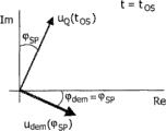
Fig. 3-5 has illustrated the component of the pretreated measuring-signal in Δ f place in complex plane, wherein Fig. 3 shows optimizing phase situation before, what Fig. 4 showed during target component is zero optimizing phase phase shift determines that Fig. 5 shows restituted signal by the next measuring phases after adapting to;
Fig. 6 shows the circuit theory diagrams according to the magnetic sensor device that comprises building-out condenser of second embodiment of the invention;
Fig. 7 shows the schematic cross-sectional of the magnetic sensor device that generates electric wire according to crosstalking comprising of third embodiment of the invention.
Embodiment
Identical Reference numeral refers to same or analogous element among the figure.
Fig. 1 has illustrated the magnetic interaction particle (for example super paramagnetic beads 3) of microelectronics magnetic sensor device to be used for the test sample chamber that specifically is used as biology sensor according to the present invention.Magneto-resistive biochips or biology sensor have attribute likely aspect sensitivity, specificity, integrality, the easy to use and cost for bio-molecular diagnostics.The example of such biochip is described among WO 2003/054566, WO 2003/054523, WO 2005/010542A2, WO2005/010543A1 and the WO 2005/038911A1, and these files are incorporated the application by reference into.
Magnetic sensor device shown in Figure 1 comprises at least one magnetic field generator, and it may be implemented as the lead 1 on the substrate (not shown) or can be in outside the sensor chip.Field generator 1 is driven by current source 4, wherein first frequency f
1The sinusoidal excitation electric current I
1Be used for generating the external magnetic field H of alternation in adjacent sample chamber
1By means of complex representation and (constant, real) amplitude I
Ex, represent exciting current I with the equation (1) of Fig. 2
1Fig. 1 also shows the second magnetic pumping electric wire 1 ' that is driven by second current source 4 ' can easily expand to many electric wires situation so that this design to be described.
The magnetic excitation field H that is generated
1The magnetic bead 3 of magnetization in the sample chamber, wherein said magnetic bead 3 can be for example as the mark of (biology) interested molecule (can be referring to the document of being quoted) about more details.Magnetic reaction field H by magnetic bead 3 generations
BThen (together with exciting field H
1The resistance of contiguous giant magnetoresistance (GMR) sensing element 2 of influence together).
In order to measure magnetic reaction field H
B, frequency f
2The sinusoidal sensor electric current I
2Conduct by other power supply 5 generations and by GMR sensing element 2.Utilize complex representation and (constant, real) amplitude I
s, represent this sensor current I with equation (2)
2
The voltage u that can measure across GMR sensor 2
GMRThe sensor signal of the resistance (thereby the magnetic field of indicating GMR sensor 2 to be stood) of indication GMR sensor 2 is provided then.
Fig. 1 is also by capacitor C
ParAnd dotted line represent excitation wire 1,1 ' and GMR sensor 2 between the parasitic capacitive coupling.Excitation wire 1,1 ' and GMR sensor 2 between this capacitive couplings and/or additional electrical perception inductive coupling go out measuring voltage u
GMRCrosstalk components u
xWith the relevant additional electric current I of crosstalking through GMR sensor 2
xCrossfire I
xWith exciting current I
1Proportional, but 90 ° of phase shifts.Crossfire I
xWith sensor current I
2Produce total current I together through GMR sensor 2
GMRProvided the corresponding mathematical description of above-mentioned electric current in equation (3) and (4), wherein α is a constant.
Fig. 1 also shows total current I
GMRInduce and have the field H that acts on the GMR sensor 2
2Self-magnetization.Equation (5) has been summarized the total magnetic field H that GMR sensor 2 is exposed to the open air
GMR, wherein β, γ and ε are constants, B is the magnetic bead density (supposing that magnetic bead evenly distributes from the teeth outwards) that will seek on the sensor surface.
The all-in resistance R of equation (6) expression GMR sensor 2
GMR, this is constant (ohm) R
0With variable item Δ R sum, described variable item Δ R depends on the total magnetic field H that popularizes (prevail) in GMR element 2 via sensor gain s
GMR
Equation (7) has provided the measuring-signal u that is generated by GMR sensor 2 and handled by signal processing circuit 20 (Fig. 1)
GMR, wherein μ, a
1, a
2, a
3, a
4, a
5, a
6It is constant.This measuring-signal u
GMR(ohm) voltage drop and additional crosstalk voltage u above-mentioned by GMR sensor 2 two ends
xForm.As seen from equation (7), measuring-signal u
GMRComprise and exciting current I
1, sensor current I
2And defined " quadrature current " I in the equation (3)
QThe proportional some components of different products.Use equation (1)-(3) and trigonometric identity, these components can be shown corresponding to characteristic frequency.Particularly, product I
1I
2And I
QI
2By difference frequency Δ f=(f
1-f
2) and (f
1+ f
2) frequency component located forms, these frequency components can not occur in other product.By in signal processing circuit 20, suitably handling measuring-signal u
GMR, for example by with its (in amplifier amplify back) by being the bandpass filter at center with difference frequency Δ f, obtained according to equation (8) through pre-service or filtered signal u
fDifference frequency Δ f is selected such that the thermonoise of GMR sensor 2 accounts for the 1/f that amplifies the noise of introducing.In order to produce interested amount, i.e. signal u
fIn the amplitude variations (it is the tolerance of magnetic bead amount on the sensor) of Δ f, the restituted signal u of the difference frequency Δ f of utilization and information signal homophase
Dem(
 ) restituted signal u in the
 detuner 11 of evaluation unit 10
fAfter the demodulation, the output signal u of evaluation unit 10
OutCan for example be low pass filtering and randomly further be handled.
(Re, illustrating in Im) ought be typically through pretreated signal u at complex plane for Fig. 3
fAt t sometime
0When being provided for evaluation unit 10 this is through pretreated signal u
fAccording to equation (8), this is through pretreated signal u
fComprise following component:
1. that look genuine or " quadrature component " or be called for short " Q component " u
Q: as explained above, (intrinsic by sensor geometries) capacitive character and inductive cross-talk cause the crossfire I by the GMR sensor
x, its frequency equals excitation frequency f
1And, the sensor current I that is applied
2Cause in the GMR sensor (automatic biasing) and be in second frequency f
2Internal magnetic field H
2Their product causes being in the Q component u of difference frequency Δ f
Q, its phase place is with respect to information carrying signal skew 90 degree.According to equation (8), this Q component u
QAmplitude be | u
Q|=2 π f
1α β sI
ExI
s, wherein α is crossfire (I
c) and the exciting current (I that applies
1) merchant I
c/ I
1, β is automatic biasing factor H
2/ I
GMR, promptly by electric current I by GMR
GMRMagnetic field intensity H in the sensitive layer of the GMR sensor of induction
2, s=Δ R/ Δ H is the sensitivity of GMR sensor.
2. magnetic cross-talk vector u
x: excitation wire 1,1 ' and (intrinsic) misalignment of GMR sensor wire 2 cause by exciting current I
1The magnetic field H of induction
1GMR response u
xAccording to equation (9), | u
x|=γ sI
ExI
s, γ=H wherein
2/ I
1Be by magnetic field intensity in the sensitive layer of the GMR of the induction by current by excitation wire and the proportionality constant between this electric current.
3. " bead vector " u
B, it causes therefore representative information carrying signal (" echo signal ") by magnetic bead.Equation (9) and (11) have provided u
B, ε=H wherein
B/ (BI
Ex) be by magnetic field intensity in the sensitive layer of the GMR of the magnetic bead of sensor surface induction and the proportionality constant between the magnetic bead density B on the sensor surface.
4. total magnetic vector or " I component " u
I=u
x+ u
B, it comprises above-mentioned magnetic cross-talk u
xWith bead vector u
B
Fig. 3 and equation (8) show through pre-service, filtered signal u
fHas the particle independent component u that looks genuine
QBecause this spurious component and in-phase component u
BSo (this is that institute is interested) quadrature is in theory can be by using and expectation information carrying signal u
B(or u
I) the modulation signal u of homophase
DemSuppress this spurious component.Yet problem is that pre-service electron device 20 is introduced and in a disguised form moves when unknown
 This makes can not select fixed modulation signal u with the information signal homophase simply
DemUse out-phase restituted signal u for example shown in Figure 3
Dem(0) can generation comprise from spurious component u
QThe measurement result of interference of unknown size.Phase shift
This makes can not select fixed modulation signal u with the information signal homophase simply
DemUse out-phase restituted signal u for example shown in Figure 3
Dem(0) can generation comprise from spurious component u
QThe measurement result of interference of unknown size.Phase shift
 May be owing to for example product tolerance, aging effect or temperature variation change.In addition,
 May because the delay in analog filtering or the digital processing (sampling) and and frequency dependence.
In view of above-mentioned Consideration, that desired is optimization solution tonal signal u
DemDemodulation phase
 So that suppress spurious component u
QThis should use at demodulation phase
So that suppress spurious component u
QThis should use at demodulation phase
 Sane, accurate adaptive algorithm obtain and do not have complicated signal processing requirement and can be suitable for analog-and digital-demodulation implementation.Because phase shift
 Become when being, so requirement self-adaptation repeatedly.
In the general solution to said circumstances, the amplitude relation in the GMR sensor 12 between magnetic excitation field and the parasitic crosstalk is changed during optimizing phase OS.This will disclose actual phase shift
 Demodulation phase then
Can be towards spurious component u
QMaximum suppress to optimize accordingly.When identical during the frequency during the optimizing phase OS and the measuring phases MS, obtained pinpoint accuracy, reason has been to avoid the phase shift of (in the signal Processing electron device) frequency dependence.
Demodulation phase then
Can be towards spurious component u
QMaximum suppress to optimize accordingly.When identical during the frequency during the optimizing phase OS and the measuring phases MS, obtained pinpoint accuracy, reason has been to avoid the phase shift of (in the signal Processing electron device) frequency dependence.
According to first specific implementation of above-mentioned general solution, making exciting current during optimizing phase OS is zero.In the embodiment in figure 1, exciting current I
1By particularly from excitation wire 1,1 ' remove and relocate again (reroute) to virtual resistance R, R ' with the resistance value that equates with excitation wire 1,1 ' resistance value (for example 10 ohm) so that make the impedance level maintenance of current source 4 and 4 ' constant.This especially needs when described current source back has its response to the analog filter parts (not shown) of impedance level sensitivity.As a result, GMR signal u
GMRAnd therefore through pretreated signal u
fOnly comprise undesired spurious component u
QDemodulation phase
 Can be adapted to be then
 So that spurious component u
QAt demodulated output signal u
OutIn be maximally suppressed.According to Fig. 1, this can by during the optimizing phase via
So that spurious component u
QAt demodulated output signal u
OutIn be maximally suppressed.According to Fig. 1, this can by during the optimizing phase via backfeed loop 12 control phase shifter able to programme 13 up to u
OutRealize till=0.
Fig. 4 shows demodulation phase and is adjusted the back schematic vector diagram corresponding with optimizing phase OS.
Fig. 5 shows follow-up measuring phases MS, wherein once more to excitation wire supply exciting current I
1Because restituted signal u
DemPhase place be adjusted now, so spurious component u
QSuppressed best.
Should be pointed out that described optimization is based on as resistor R, R ' is not close to excitation wire 1, capacitive couplings (rather than based on inductive couplings) 1 ' time.Yet this does not influence net result, the phase place that reason is capacitive character and inductive cross-talk electric current all with the magnetic signal quadrature of expectation.So demodulation phase of being found
 Also suppress best because the spurious component due to the inductive cross-talk.
The purpose of resistor R, R ' (serving as dummy excitation wires) is to keep exciting current I in optimizing phase and measuring phases
1Phase place.This is at described exciting current I
1Be to be even more important when generating via complex impedance (high-order (low pass) wave filter for example, it makes the phase place of exciting current change very sensitive to loaded impedance).
In second embodiment of magnetic sensor device shown in Figure 6, parasitic (capacitive character, inductive) coupling is increased, and preferably makes it be in very big ascendancy with respect to magnetic signal.This is by adding extra coupling element, for example by add capacitor C between excitation wire 1 and GMR sensor 2 during optimizing phase OS
AddRealize.Be similar to the embodiment of Fig. 1, demodulation phase
 Quilt is towards u during optimizing phase OS
Out=0 situation is optimized, so that suppress quadrature component u the biglyyest
QDuring measuring phases MS subsequently, this demodulation phase is used for detecting magnetic signal then.
Quilt is towards u during optimizing phase OS
Out=0 situation is optimized, so that suppress quadrature component u the biglyyest
QDuring measuring phases MS subsequently, this demodulation phase is used for detecting magnetic signal then.
This scheme is exceedingly useful when magnetic signal is very little, and is for example exceedingly useful when suppressing magnetic cross-talk by perpendicular alignmnet excitation wire (one or more) and GMR sensor.
In substituting embodiment, be increased during parasitic (capacitive character, inductive) is coupling in the optimizing phase, but it is top dog.Two kinds of responses appear in the result, can derive best demodulation phase according to these responses.
The schematic cross-sectional of the 3rd embodiment during optimizing phase OS of magnetic sensor device has been shown among Fig. 7.This embodiment comprises additional " electric wire of crosstalking " 6 (for example being depicted as the top that is positioned at GMR sensor 2 abreast) that passes from the sensitive plane of GMR sensor 2 (sensitive plane).When during optimizing phase OS, supplying exciting current I to this electric wire 6 of crosstalking
1The time magnetic " the crosstalk " H that generated
3In GMR sensor 2, generate strong magnetic cross-talk signal then.Thereby magnetic cross-talk is enlarged markedly, and preferably makes it with respect to quadrature component u
QBe in very big ascendancy.Be changed as far as possible for a short time if the capacitive character (and inductive) between GMR sensor 2 and the electric current line 1,1 ', 6 is crosstalked, then the latter can be kept constant substantially.This for example additional crosstalk electric wire 6 from the distance of GMR sensor 2 and excitation wire 1,1 ' from the distance-like of GMR sensor 2 like and during optimizing phase OS not to the realization of getting off of the situation of excitation wire 1,1 ' supply exciting current.Demodulation phase
 Can be towards " u during optimizing phase OS
Out=maximal value " situation be optimized so that during measuring phases MS subsequently, will farthest suppress quadrature component u
Q
Can be towards " u during optimizing phase OS
Out=maximal value " situation be optimized so that during measuring phases MS subsequently, will farthest suppress quadrature component u
Q
Though described the present invention with reference to specific embodiment above, various modifications and expansion are possible, for example:
-except molecular assay, use according to magnetic sensor device of the present invention and can also detect major part (moiety), for example the several portions, tissue extract of cell, virus or cell or virus, or the like.
-described detection can take place under the scan condition that is with or without with respect to the sensing element of biosensor surface.
-measurement data can be used as the end points measurement and obtains, and (kinetically) or tracer signal off and on with can passing through motion.
-can directly detect by method for sensing with the magnetic particle of marking.Particle can also be further processed before detecting.Further the example of handling be add material or revise (biology) chemistry of mark or physical attribute so that detect.
-this Apparatus and method for can use with some biochemical assay types, for example combination/non-binding the analysis of described assay types, sandwich assay (sandwich assay), competitive analysis, substitutability analysis (replacement assay), enzyme analysis, or the like.
-this Apparatus and method for is suitable for sensor multiplexing (the different sensors and sensor surface of promptly parallel use), mark multiplexing (the dissimilar mark of promptly parallel use) and chamber multiplexing (promptly walk abreast and use different reaction chambers).
-this Apparatus and method for can be as quick, sane, easy-to-use care location (the point of care) biology sensor at the small sample volume.Reaction chamber can be the disposable object that will use with compact reader, contains one or more magnetic fields generating apparatus and one or more pick-up unit.And device of the present invention, method and system can be used in format high throughput (throughput) test of robotization.In this case, reaction chamber is orifice plate or the test tube that for example is fitted in the self-reacting device.
It is to be noted at last: in the present invention, term " comprises " does not get rid of other element or step, and " one " or " one " does not get rid of a plurality of, and the function of some devices can be realized in single processor or other unit.The invention reside in each combination of each novel characteristic feature and characteristic feature.In addition, the Reference numeral in the claim should not be interpreted as limiting their scope.
Claims (13)
1. magnetic sensor device that is used for detection of magnetized particles (3) comprises:
-sample chamber can provide described magnetized particles (3) in this sample chamber;
-at least one magnetic field generator (1,1 '), it is by comprising first frequency (f
1) exciting current (I
1) drive to be used for generating magnetic excitation field (H in the sample chamber
1);
-at least one magnetic sensing element (2) that is associated, it is by comprising second frequency (f
2) sensor current (I
2) drive to be used to generate measuring-signal (u
GMR);
-signal processing circuit (20) is used for from described measuring-signal (u
GMR) generate comprise preset frequency (Δ f) through pretreated signal (u
f);
-evaluation unit (10) is used for from described through pretreated signal (u
f) the middle spurious component (u that separates
Q), the existence of the magnetized particles (3) in this spurious component and the described sample chamber is irrelevant.
2. determine to may further comprise the steps the method for the magnetized particles (3) in the sample chamber by means of magnetic sensor device for one kind:
-utilize to comprise first frequency (f
1) exciting current (I
1) magnetic field generator (1,1 ') that drives generates magnetic excitation field (H
1) and described sample chamber;
-utilize to comprise second frequency (f
2) sensor current (I
2) the magnetic sensing element (2) that drives generates measuring-signal (u
GMR);
-utilize signal processing circuit (20) from described measuring-signal (u
GMR) generate through pretreated signal (u
f), wherein saidly comprise preset frequency (Δ f) through pretreated signal;
-utilize evaluation unit (10) from described through pretreated signal (u
f) the middle spurious component (u that separates
Q), the existence of the magnetized particles (3) in this spurious component and the described sample chamber is irrelevant.
3. magnetic sensor device as claimed in claim 1 or method as claimed in claim 2 are characterised in that described preset frequency (Δ f) is first frequency (f
1) and second frequency (f
2) between poor.
4. magnetic sensor device as claimed in claim 1 or method as claimed in claim 2 are characterised in that: described through pretreated signal (u
f) comprise magnetic reaction field (H by the particle in the described sample chamber (3)
B) target component (u that generates
B), described particle is by magnetic excitation field (H
1) magnetization; And described spurious component (u
Q) have same frequency (Δ f) with respect to described target component, but have phase shift, be specially 90 °.
5. magnetic sensor device as claimed in claim 1 or method as claimed in claim 2 are characterised in that described spurious component (u
Q) by the self-magnetization (H of described magnetic sensing element (2)
2) and in conjunction with the capacitive character between described magnetic field generator (1,1 ') and the described magnetic sensing element (2) and/or inductive cross-talk and generate.
6. magnetic sensor device as claimed in claim 1 or method as claimed in claim 2 are characterised in that described through pretreated signal (u
f) comprise variable phase shift (
 ).
).
7. magnetic sensor device as claimed in claim 6 or method, be characterised in that described evaluation unit (10) comprise be used for determining described variable phase shift (
 ) phase estimating device (12,13).
8. magnetic sensor device as claimed in claim 1 or method as claimed in claim 2, be characterised in that described magnetic sensor device comprise reference circuit (6, R, R ', C
Add), this reference circuit (6, R, R ', C
Add) can optionally be activated to be used to change described spurious component (u by described evaluation unit (10)
Q) relative amplitude.
9. magnetic sensor device as claimed in claim 8 or method are characterised in that described reference circuit comprises bypassed resistor (R, R '), via the described exciting current (I of described bypassed resistor
1) can the described magnetic field generator of bypass (1,1 ').
10. magnetic sensor device as claimed in claim 8 or method are characterised in that described reference circuit comprises capacitor (C
Add), this capacitor is coupled described magnetic field generator (1,1 ') and described magnetic sensing element (2).
11. magnetic sensor device as claimed in claim 8 or method are characterised in that described reference circuit comprises and are used to generate magnetic cross-talk field (H
3) at least one complementary field generator (6), described magnetic cross-talk field can be detected by magnetic sensing element (2).
12. magnetic sensor device as claimed in claim 1 or method as claimed in claim 2 are characterised in that described magnetic sensing element comprises coil, Hall element, plane Hall element, fluxgate sensor, SQUID, magnetic resonance sensors, magnetoresistive transducer or as the magnetoresistive transducer of GMR (2), AMR or TMR element.
13. the use of magnetic sensor device as claimed in claim 1 in molecular diagnosis, biological sample analysis and/or chemical example analysis, particularly micromolecule detect.
Applications Claiming Priority (2)
| Application Number | Priority Date | Filing Date | Title |
|---|---|---|---|
| EP06126394.3 | 2006-12-18 | ||
| EP06126394 | 2006-12-18 |
Publications (1)
| Publication Number | Publication Date |
|---|---|
| CN101563610A true CN101563610A (en) | 2009-10-21 |
Family
ID=39370808
Family Applications (1)
| Application Number | Title | Priority Date | Filing Date |
|---|---|---|---|
| CNA2007800467657A Pending CN101563610A (en) | 2006-12-18 | 2007-12-12 | Magnetic sensor device with suppression of spurious signal components |
Country Status (5)
| Country | Link |
|---|---|
| US (1) | US20100001722A1 (en) |
| EP (1) | EP2095121A2 (en) |
| JP (1) | JP2010513863A (en) |
| CN (1) | CN101563610A (en) |
| WO (1) | WO2008075262A2 (en) |
Cited By (1)
| Publication number | Priority date | Publication date | Assignee | Title |
|---|---|---|---|---|
| CN112119311A (en) * | 2018-07-27 | 2020-12-22 | 泽普托生命技术有限责任公司 | Systems and methods for processing analyte signals in GMR-based biomarker detection |
Families Citing this family (4)
| Publication number | Priority date | Publication date | Assignee | Title |
|---|---|---|---|---|
| US8442787B2 (en) * | 2010-04-30 | 2013-05-14 | Infineon Technologies Ag | Apparatus, sensor circuit, and method for operating an apparatus or a sensor circuit |
| US20140099663A1 (en) * | 2010-11-15 | 2014-04-10 | Regents Of The University Of Minnesota | Gmr sensor |
| CN103064049B (en) * | 2012-12-21 | 2014-11-26 | 北京航空航天大学 | Three-dimensional standard magnetic field generating device based on phase synchronization |
| ES2610384T3 (en) * | 2013-08-30 | 2017-04-27 | Magnomics, Sa | High performance scalable biodetection platform |
Family Cites Families (14)
| Publication number | Priority date | Publication date | Assignee | Title |
|---|---|---|---|---|
| EP1697755A1 (en) * | 2003-07-30 | 2006-09-06 | Koninklijke Philips Electronics N.V. | On-chip magnetic sensor device with suppressed cross-talk |
| US20060194327A1 (en) * | 2003-07-30 | 2006-08-31 | Koninklijke Philips Electronics N.V. | On-chip magnetic particle sensor with improved snr |
| JP4392429B2 (en) * | 2003-07-30 | 2010-01-06 | コーニンクレッカ フィリップス エレクトロニクス エヌ ヴィ | Integrated 1 / f noise removal method of magnetoresistive nanoparticle sensor |
| ATE429649T1 (en) * | 2005-09-22 | 2009-05-15 | Koninkl Philips Electronics Nv | MAGNETIC FIELD SENSOR WITH FILTER |
| WO2007042959A2 (en) * | 2005-10-12 | 2007-04-19 | Koninklijke Philips Electronics N.V. | Magnetic sensor device with different internal operating frequencies |
| US20080238411A1 (en) * | 2005-10-19 | 2008-10-02 | Koninklijke Philips Electronics, N.V. | Magneto-Resistive Nano-Particle Sensor |
| US20090009156A1 (en) * | 2006-02-03 | 2009-01-08 | Konninklijke Philips Electronics N.V. | Magnetic Sensor Device With Reference Unit |
| WO2007105141A2 (en) * | 2006-03-15 | 2007-09-20 | Koninklijke Philips Electronics N. V. | Magnetic sensor device with gain stabilization |
| WO2007105143A2 (en) * | 2006-03-15 | 2007-09-20 | Koninklijke Philips Electronics N. V. | Sensor device with alternating excitation fields |
| CN101467059A (en) * | 2006-05-09 | 2009-06-24 | 皇家飞利浦电子股份有限公司 | Magnetic sensor device with field generators and sensors |
| WO2007132374A1 (en) * | 2006-05-09 | 2007-11-22 | Koninklijke Philips Electronics N. V. | A magnetic sensor device for and a method of sensing magnetic particles |
| CN101438179A (en) * | 2006-05-09 | 2009-05-20 | 皇家飞利浦电子股份有限公司 | A magnetic sensor device for and a method of sensing magnetic particles |
| JP2009539098A (en) * | 2006-05-30 | 2009-11-12 | コーニンクレッカ フィリップス エレクトロニクス エヌ ヴィ | Adaptive magnetic field compensation sensor device |
| JP2010500547A (en) * | 2006-08-09 | 2010-01-07 | コーニンクレッカ フィリップス エレクトロニクス エヌ ヴィ | Microchip magnetic sensor device |
-
2007
- 2007-12-12 EP EP07849455A patent/EP2095121A2/en not_active Withdrawn
- 2007-12-12 CN CNA2007800467657A patent/CN101563610A/en active Pending
- 2007-12-12 US US12/518,890 patent/US20100001722A1/en not_active Abandoned
- 2007-12-12 WO PCT/IB2007/055057 patent/WO2008075262A2/en active Application Filing
- 2007-12-12 JP JP2009540955A patent/JP2010513863A/en not_active Withdrawn
Cited By (1)
| Publication number | Priority date | Publication date | Assignee | Title |
|---|---|---|---|---|
| CN112119311A (en) * | 2018-07-27 | 2020-12-22 | 泽普托生命技术有限责任公司 | Systems and methods for processing analyte signals in GMR-based biomarker detection |
Also Published As
| Publication number | Publication date |
|---|---|
| JP2010513863A (en) | 2010-04-30 |
| US20100001722A1 (en) | 2010-01-07 |
| WO2008075262A2 (en) | 2008-06-26 |
| EP2095121A2 (en) | 2009-09-02 |
| WO2008075262A3 (en) | 2008-08-21 |
Similar Documents
| Publication | Publication Date | Title |
|---|---|---|
| De Boer et al. | An integrated and sensitive detection platform for magneto-resistive biosensors | |
| JP4776696B2 (en) | Method and apparatus for nondestructive evaluation of defects in metal objects | |
| US20080309329A1 (en) | On-Chip Magnetic Sensor Device with Suppressed Cross-Talk | |
| US20090009156A1 (en) | Magnetic Sensor Device With Reference Unit | |
| US20090184706A1 (en) | Sensor device with adaptive field compensation | |
| US20090072815A1 (en) | Calibration of a magnetic sensor device | |
| CN1829908B (en) | Circuit, bio-chip and method for removing noise of a magneto-resistive nano-particle sensor | |
| US20090237844A1 (en) | Magnetic sensor device for and a method of sensing magnetic particles | |
| JP2009530602A (en) | Sensor device using AC excitation magnetic field | |
| EP1817600A2 (en) | Magnetic sensor with parallel magnetic sensor strips | |
| CN101563610A (en) | Magnetic sensor device with suppression of spurious signal components | |
| WO2007105141A2 (en) | Magnetic sensor device with gain stabilization | |
| CN101563611A (en) | Magnetic sensor device with robust signal processing | |
| EP1949122A2 (en) | Sensor device with generator and sensor current sources | |
| WO2007132367A1 (en) | Accurate magnetic biosensor | |
| EP1929319B1 (en) | Magnetic sensor device with filtering means |
Legal Events
| Date | Code | Title | Description |
|---|---|---|---|
| C06 | Publication | ||
| PB01 | Publication | ||
| C10 | Entry into substantive examination | ||
| SE01 | Entry into force of request for substantive examination | ||
| C02 | Deemed withdrawal of patent application after publication (patent law 2001) | ||
| WD01 | Invention patent application deemed withdrawn after publication |
Application publication date: 20091021 |