CN101558236B - Wind driven electric power generator and method of constructing wind driven electric power generator - Google Patents
Wind driven electric power generator and method of constructing wind driven electric power generator Download PDFInfo
- Publication number
- CN101558236B CN101558236B CN2008800009973A CN200880000997A CN101558236B CN 101558236 B CN101558236 B CN 101558236B CN 2008800009973 A CN2008800009973 A CN 2008800009973A CN 200880000997 A CN200880000997 A CN 200880000997A CN 101558236 B CN101558236 B CN 101558236B
- Authority
- CN
- China
- Prior art keywords
- anterior
- dividing body
- rear portion
- cabin
- lid
- Prior art date
- Legal status (The legal status is an assumption and is not a legal conclusion. Google has not performed a legal analysis and makes no representation as to the accuracy of the status listed.)
- Expired - Fee Related
Links
- 238000000034 method Methods 0.000 title claims abstract description 31
- 238000005304 joining Methods 0.000 claims description 59
- 238000009434 installation Methods 0.000 claims description 13
- 238000005266 casting Methods 0.000 claims description 5
- 238000010276 construction Methods 0.000 abstract description 15
- 230000015572 biosynthetic process Effects 0.000 description 11
- 230000000694 effects Effects 0.000 description 6
- 230000005611 electricity Effects 0.000 description 6
- 229920002430 Fibre-reinforced plastic Polymers 0.000 description 5
- 101150042248 Mgmt gene Proteins 0.000 description 5
- 239000011151 fibre-reinforced plastic Substances 0.000 description 5
- 238000007654 immersion Methods 0.000 description 4
- 230000000712 assembly Effects 0.000 description 3
- 238000000429 assembly Methods 0.000 description 3
- 210000001503 joint Anatomy 0.000 description 3
- 238000005520 cutting process Methods 0.000 description 2
- 230000033001 locomotion Effects 0.000 description 2
- 238000004519 manufacturing process Methods 0.000 description 2
- 241000282326 Felis catus Species 0.000 description 1
- 230000005540 biological transmission Effects 0.000 description 1
- 230000003028 elevating effect Effects 0.000 description 1
- 238000003032 molecular docking Methods 0.000 description 1
- 230000002040 relaxant effect Effects 0.000 description 1
- 238000000926 separation method Methods 0.000 description 1
Images


Classifications
-
- F—MECHANICAL ENGINEERING; LIGHTING; HEATING; WEAPONS; BLASTING
- F03—MACHINES OR ENGINES FOR LIQUIDS; WIND, SPRING, OR WEIGHT MOTORS; PRODUCING MECHANICAL POWER OR A REACTIVE PROPULSIVE THRUST, NOT OTHERWISE PROVIDED FOR
- F03D—WIND MOTORS
- F03D13/00—Assembly, mounting or commissioning of wind motors; Arrangements specially adapted for transporting wind motor components
- F03D13/10—Assembly of wind motors; Arrangements for erecting wind motors
-
- F—MECHANICAL ENGINEERING; LIGHTING; HEATING; WEAPONS; BLASTING
- F03—MACHINES OR ENGINES FOR LIQUIDS; WIND, SPRING, OR WEIGHT MOTORS; PRODUCING MECHANICAL POWER OR A REACTIVE PROPULSIVE THRUST, NOT OTHERWISE PROVIDED FOR
- F03D—WIND MOTORS
- F03D1/00—Wind motors with rotation axis substantially parallel to the air flow entering the rotor
- F03D1/06—Rotors
-
- F—MECHANICAL ENGINEERING; LIGHTING; HEATING; WEAPONS; BLASTING
- F05—INDEXING SCHEMES RELATING TO ENGINES OR PUMPS IN VARIOUS SUBCLASSES OF CLASSES F01-F04
- F05B—INDEXING SCHEME RELATING TO WIND, SPRING, WEIGHT, INERTIA OR LIKE MOTORS, TO MACHINES OR ENGINES FOR LIQUIDS COVERED BY SUBCLASSES F03B, F03D AND F03G
- F05B2240/00—Components
- F05B2240/10—Stators
- F05B2240/14—Casings, housings, nacelles, gondels or the like, protecting or supporting assemblies there within
-
- Y—GENERAL TAGGING OF NEW TECHNOLOGICAL DEVELOPMENTS; GENERAL TAGGING OF CROSS-SECTIONAL TECHNOLOGIES SPANNING OVER SEVERAL SECTIONS OF THE IPC; TECHNICAL SUBJECTS COVERED BY FORMER USPC CROSS-REFERENCE ART COLLECTIONS [XRACs] AND DIGESTS
- Y02—TECHNOLOGIES OR APPLICATIONS FOR MITIGATION OR ADAPTATION AGAINST CLIMATE CHANGE
- Y02E—REDUCTION OF GREENHOUSE GAS [GHG] EMISSIONS, RELATED TO ENERGY GENERATION, TRANSMISSION OR DISTRIBUTION
- Y02E10/00—Energy generation through renewable energy sources
- Y02E10/70—Wind energy
- Y02E10/72—Wind turbines with rotation axis in wind direction
-
- Y—GENERAL TAGGING OF NEW TECHNOLOGICAL DEVELOPMENTS; GENERAL TAGGING OF CROSS-SECTIONAL TECHNOLOGIES SPANNING OVER SEVERAL SECTIONS OF THE IPC; TECHNICAL SUBJECTS COVERED BY FORMER USPC CROSS-REFERENCE ART COLLECTIONS [XRACs] AND DIGESTS
- Y10—TECHNICAL SUBJECTS COVERED BY FORMER USPC
- Y10S—TECHNICAL SUBJECTS COVERED BY FORMER USPC CROSS-REFERENCE ART COLLECTIONS [XRACs] AND DIGESTS
- Y10S416/00—Fluid reaction surfaces, i.e. impellers
- Y10S416/50—Vibration damping features
-
- Y—GENERAL TAGGING OF NEW TECHNOLOGICAL DEVELOPMENTS; GENERAL TAGGING OF CROSS-SECTIONAL TECHNOLOGIES SPANNING OVER SEVERAL SECTIONS OF THE IPC; TECHNICAL SUBJECTS COVERED BY FORMER USPC CROSS-REFERENCE ART COLLECTIONS [XRACs] AND DIGESTS
- Y10—TECHNICAL SUBJECTS COVERED BY FORMER USPC
- Y10T—TECHNICAL SUBJECTS COVERED BY FORMER US CLASSIFICATION
- Y10T29/00—Metal working
- Y10T29/49—Method of mechanical manufacture
- Y10T29/49316—Impeller making
-
- Y—GENERAL TAGGING OF NEW TECHNOLOGICAL DEVELOPMENTS; GENERAL TAGGING OF CROSS-SECTIONAL TECHNOLOGIES SPANNING OVER SEVERAL SECTIONS OF THE IPC; TECHNICAL SUBJECTS COVERED BY FORMER USPC CROSS-REFERENCE ART COLLECTIONS [XRACs] AND DIGESTS
- Y10—TECHNICAL SUBJECTS COVERED BY FORMER USPC
- Y10T—TECHNICAL SUBJECTS COVERED BY FORMER US CLASSIFICATION
- Y10T29/00—Metal working
- Y10T29/49—Method of mechanical manufacture
- Y10T29/49636—Process for making bearing or component thereof
- Y10T29/49698—Demounting
Landscapes
- Engineering & Computer Science (AREA)
- Life Sciences & Earth Sciences (AREA)
- Sustainable Development (AREA)
- Sustainable Energy (AREA)
- Chemical & Material Sciences (AREA)
- Combustion & Propulsion (AREA)
- Mechanical Engineering (AREA)
- General Engineering & Computer Science (AREA)
- Wind Motors (AREA)
Abstract
A wind driven electric power generator and a method of constructing a wind driven electric power generator. A wind driven electric power generator, particularly a large-sized wind driven electric power generator , can be constructed with minimum construction costs and can be constructed with minimum limitation by weather. The wind driven electric power generator has a rotor head to which wind blades are attached and rotationally driven by wind force received by the wind blades, a front split body (11) placed on a column and forming a nacelle to which the rotor head is attached, a rear split body (21) attached on the front split body (11) and forming the nacelle (3), a front frame (12) mounted on the front split body (11) and supporting, at a position between the rotor head and the column, a load applied to the rotor head, a rear frame (22) mounted on the rear split body (21) and attached to the front frame (12), a front cover (15) for covering around the front split body (11), and a rear cover (24) for covering around the rear split body (21).
Description
Technical field
The invention relates to the building method of a kind of wind generating unit and wind generating unit.
Background technique
In recent years, be purpose with the output that increases wind generating unit etc., attempt to make windmill to maximize.Along with the maximization of windmill, uprise to the height of windmill wheel hub, and the weight in cabin has also increased.
In order to tackle this variation, brought the problem that used hoist also maximizes, construction cost increases when building windmill.
In order to address these problems, people have proposed to cut apart the method (reference example such as non-patent literature 1) that the rotation blade, cabin of windmill etc. built windmill.
According to said method, can suppress to build the maximization of used hoist, and then suppress the increase of construction cost.
Non-patent literature 1: " 4 kinds of new motions ", 02: decompose the cabin and cut apart blade, (online), put down into retrieved on October 5th, 18,
Internet<UPL:http://www.fhi.co.jp/ecotechnology/wind/tech/index.html>
According to said method,, can suppress these parts are risen to the maximization of the hoist of pillar front end by the cabin being divided into three parts of Business Information and IT Solution Mgmt Dep, driving mechanism portion and hub portion.In the method, at first, architecture configuration on the front end of pillar, afterwards, is configured in driving mechanism portion etc. in the Business Information and IT Solution Mgmt Dep from the top.Therefore, open wide above the Business Information and IT Solution Mgmt Dep, can dispose driving mechanism portion etc.
That is to say that in the middle of building, worry rainwater etc. might immerse in the Business Information and IT Solution Mgmt Dep, even the weather of light rain also might produce fault in the construction of windmill above opening wide.
Further, be installed in the Business Information and IT Solution Mgmt Dep that is provided with generator etc. owing to transmit the driving mechanism portion of hub portion rotation, so, might aim between the two and produce big deviation.
The present invention is in order to address the above problem proposition, its objective is, provide a kind of reduce the construction cost of large-sized wind-driven generator particularly and can relax that weather causes to the wind generating unit of the restriction of building time and the building method of wind generating unit.
Summary of the invention
To achieve these goals, the present invention adopts following means.
The present invention's the 1st form provides a kind of wind generating unit, it is characterized in that, is provided with: a plurality of windmill rotation blades are installed, the rotor head that the wind-force that is subjected to by a plurality of windmill rotation blades is driven in rotation; Be configured on the pillar, be configured for installing the anterior dividing body in the cabin of above-mentioned rotor head; Be installed on this front portion dividing body, constitute the rear portion dividing body in above-mentioned cabin; Be arranged on the above-mentioned anterior dividing body, between above-mentioned rotor head and above-mentioned pillar, support to act on the anterior framework of the load on the above-mentioned rotor head; Be arranged on the dividing body of above-mentioned rear portion, be installed in the rear portion framework on the above-mentioned anterior framework; Cover above-mentioned anterior dividing body front portion lid on every side; And the rear portion that covers around the dividing body of above-mentioned rear portion is covered.
The 1st form according to the present invention, because engine compartment cut apart by anterior dividing body and rear portion and constitutes, so, with one-piece type cabin comparison, the miniaturization of the hoist of necessity in the time of can realizing building wind generating unit.Further, be used to carry the vehicle of anterior dividing body and rear portion dividing body, compare available dilly with the vehicle of carrying one-piece type cabin.Like this, do not need to use large-scale hoist or vehicle, so, the increase of construction cost suppressed.
Because anterior dividing body and rear portion dividing body cover by anterior lid and rear portion lid respectively, so, when building wind generating unit, be not vulnerable to the influence of weather.For example, even the rainy day etc. also can prevent the immersion of rainwater to front portion and dividing body inside, rear portion.
In the 1st form of foregoing invention, wish that above-mentioned anterior framework forms by casting.
By adopting such measure, owing to the degrees of freedom that can improve anterior framework shape, so anterior framework can form the shape that is suitable for supporting to act on the load on the rotor head.Therefore, can prevent the increase of anterior framework weight, prevent to be used for the maximization of the hoist of construction of wind generating unit or vehicle etc.
In the 1st form of foregoing invention, preferably, between the front end of above-mentioned anterior dividing body and above-mentioned pillar, be provided with the rotation dividing body that makes above-mentioned cabin and rotor head can center on the vertical axis rotation.
By adopting such measure, cut the body separation by the mechanism that makes the rotation of cabin and rotor head as the rotation dividing body and from forward part, can realize the miniaturization and the lightweight of anterior dividing body.Therefore, can prevent to be used for the maximization of the hoist, vehicle etc. of the construction of wind generating unit.
Further, by the rotation dividing body is set, the shape of the anterior framework of anterior dividing body can be formed the shape that is more suitable for supporting to act on the load on the rotor head.Therefore, can more effectively prevent the increase of anterior framework weight, prevent to be used for the maximization of the hoist of construction of wind generating unit or vehicle etc.
In the 1st form of foregoing invention, wish that the binding end of above-mentioned anterior framework and above-mentioned rear portion framework is configured in the above-mentioned pillar side in above-mentioned cabin, above-mentioned at least relatively binding end between above-mentioned anterior dividing body and above-mentioned rear portion dividing body leaves the position of above-mentioned pillar, gap when forming above-mentioned anterior framework and combining with above-mentioned rear portion framework, and, be provided with the joining portion that is used for this gap of landfill.
By adopting such measure, because anterior dividing body and rear portion dividing body are by combining the binding end of anterior framework with the rear portion framework and combination.At this moment, forwardly form above-mentioned gap on dividing body and the rear portion dividing body, so the end that makes the pillar side of binding end is the end separating of downside, and can make from the end that pillar leaves is the end contact of upside.Therefore,, be easy to carry out the aligning of rear portion dividing body, be easy to realize the operation that combines of aerial anterior dividing body and rear portion dividing body with crane lifting rear portion dividing body and when being connected with anterior dividing body.
Further, forwardly dividing body is with after the rear portion dividing body combines, because above-mentioned gap is by the joining portion landfill, so, can prevent the immersions in the cabin such as rainwater.
In the 1st form of foregoing invention, wish that above-mentioned joining portion is to cover the front portion lid of above-mentioned anterior dividing body and to cover the lid joining portion that engages between the rear portion lid of above-mentioned rear portion dividing body, this lid joining portion is provided with to the inside in above-mentioned cabin extends and the anterior lip portion that engages with above-mentioned anterior lid and extend and cover the rear flange portion that engages with above-mentioned rear portion to the inside in above-mentioned cabin, and the face that constitutes above-mentioned anterior lip portion and above-mentioned rear flange portion is the face that crosses one another.
By adopting such measure, be cross one another owing to constitute the face of anterior lip portion and rear portion lid joint respectively, so, even the relative position of anterior lid and rear portion lid is not certain, also can be with covering the gap of landfill front portion, joining portion lid with the rear portion lid.
For example,, move along the direction that the width direction relative to above-mentioned gap intersects by covering the joining portion no matter above-mentioned gap broadens or narrows down, but the landfill gap.Further, even forwardly the face of Gai face and rear portion lid constitutes under the situation of step, but by landfill gap still, lid joining portion.
Therefore, need not be more anterior relatively lid or rear portion lid are processed extraly, can carry out the joints of two lids.Further, can prevent that rainwater from leaking to the cabin between front portion lid and rear portion lid.
The present invention's the 2nd form provides a kind of building method of wind generating unit, it is characterized in that, comprising: the anterior dividing body installation procedure of the anterior dividing body of the rotor head with a plurality of windmill rotation blades is installed in configuration on pillar; To be installed in the rear portion dividing body installation procedure on the above-mentioned anterior dividing body with the rear portion dividing body that anterior dividing body constitutes the cabin; And in the gap between above-mentioned anterior dividing body and above-mentioned rear portion dividing body, configuration is used for the joining portion arrangement step at the joining portion in this gap of landfill.
The 2nd form according to the present invention after being installed in anterior dividing body on the pillar, is installed in the rear portion dividing body on this front portion dividing body, constitute the cabin thus, therefore, compare the miniaturization of the hoist of necessity in the time of to realize building wind generating unit with the situation in one-piece type cabin.Further, carry the vehicle of anterior dividing body and rear portion dividing body, compare available dilly with the vehicle of carrying one-piece type cabin.Like this, do not need to use large-scale hoist, vehicle, so, the increase of construction cost suppressed.
The wind generating unit of the 1st form according to the present invention, because engine compartment cut apart by anterior dividing body and rear portion and constitutes, so, can reach and reduce the particularly effect of the construction cost of large-sized wind-driven generator.Further, because anterior dividing body and rear portion dividing body be respectively by anterior lid and rear portion lid covering, so, can realize relaxing that weather causes to the effect of the restriction of building time.
The building method of the wind generating unit of the 2nd form according to the present invention after being installed in anterior dividing body on the pillar, constitutes the cabin by the rear portion dividing body is installed, and therefore, can reach and reduce the particularly effect of the construction cost of large-sized wind-driven generator.
Description of drawings
Fig. 1 is the explanatory drawing that the wind generating unit of a form of implementation of the present invention constitutes.
Fig. 2 is the partial enlarged drawing of the engine room structure of explanatory drawing 1.
Fig. 3 is the ideograph (schematic representation of cutting apart) that the various assemblies in the cabin of explanatory drawing 2 constitute.
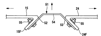
Fig. 4 be the front portion lid that is used for explanatory drawing 3, lid joining portion and with the ideograph of the formation at the joining portion of rear portion lid.
Fig. 5 is the flow chart of building method in cabin of the wind generating unit of explanatory drawing 1.
Fig. 6 is the ideograph of building method in the cabin of explanatory drawing 1.
Fig. 7 is the ideograph of building method in the cabin of explanatory drawing 1.
Fig. 8 is the ideograph of building method in the cabin of explanatory drawing 1.
Fig. 9 is the ideograph of building method in the cabin of explanatory drawing 1.
Figure 10 is the formation schematic representation that is used to illustrate under the situation that narrows down at interval between anterior lid and the rear portion lid.
Figure 11 is the formation schematic representation that is used to illustrate under the situation that broadens at interval between anterior lid and the rear portion lid.
Figure 12 is used to illustrate the schematic representation that constitutes under the location dislocation situation of the position of the anterior face that covers and the face that the rear portion is covered.
Symbol description
The 1-wind generating unit, the 2-pillar, the 3-cabin, the 5-rotor head, 6-windmill rotation blade, 11-front assembly (anterior dividing body), 21-rear assembly (rear portion dividing body), 31-swivel assembly (rotation dividing body), 12-cabin platen (anterior framework), the anterior binding end (binding end) of 16-, the anterior lid of 15-, 22-rear portion framework, 25-rear portion binding end (binding end), 24-rear portion lid, 41-framed joint portion, 51-covers the joining portion, 52-the 1st joining portion flange (anterior lip portion), 53-the 2nd joining portion flange (rear flange portion), S2-front assembly installation procedure (anterior dividing body installation procedure), S3-rear assembly installation procedure (rear portion dividing body installation procedure), S4-joining portion arrangement step.
Embodiment
With reference to Fig. 1~Figure 12, the wind generating unit of an embodiment of the present invention is described.
Fig. 1 is the explanatory drawing that the wind generating unit of the invention process form constitutes.
As shown in Figure 1, wind generating unit 1 is the device that carries out wind-power electricity generation.In this wind generating unit 1, be provided with: the upright pillar 2 that is located on the basic B; Be arranged on the cabin 3 of pillar 2 upper ends; Can and be arranged on rotor head 5 on the cabin 3 around the rotational of approximate horizontal; Be used to cover the head lid 4 of rotor head 5; With radial a plurality of windmill rotation blades 6 of installing around the spin axis of rotor head 5; And the power generating equipment 7 of generating electricity by the rotation of rotor head 5.
In addition, in this form of implementation, although understand and to be applicable to the example that 3 windmill rotation blades 6 are set, still, the number of windmill rotation blade 6 is not limited to 3, also is applicable to 2 situation or the situation more than 3, is not particularly limited.
As shown in Figure 1, pillar 2 is to constitute (top of Fig. 1) column of extending upwards from basic B, for example, constitutes a plurality of unit are linked along the vertical direction.The topmost part at pillar 2 is provided with cabin 3.Under the situation that pillar 2 is made of a plurality of unit, cabin 3 is set being arranged on the unit of the topmost part.
Fig. 2 is the partial enlarged drawing of cabin 3 structures of explanatory drawing 1.
Rotor head 5 is rotatably being supported as shown in Figures 1 and 2 in cabin 3, and inside accommodates the power generating equipment 7 of generating electricity by the rotation of rotor head 5.
Cabin 3 roughly is made of 3 assemblies of front assembly (anterior dividing body) 11, rear assembly (rear portion dividing body) 21 and swivel assembly (rotation dividing body) 31.
Fig. 3 is the ideograph that the various assemblies 11,21,31 in the cabin 3 of explanatory drawing 2 constitute.(schematic representation of cutting apart).
As shown in Figure 3, forwardly assembly 11 is provided with cabin platen (anterior framework) 12; Anterior winch framework 13; Booster engine 14 and anterior lid 15.
As shown in Figure 3, cabin platen 12 be with approximate horizontal be installed in the casting structure body that the 12A of table top portion of swivel assembly 31 upper ends and the housing 12B one that covers the 12A of this table top portion from the top constitute.
On housing 12B, forming the 1st opening portion 12H1 with rotor head 5 opposed positions (left part of Fig. 3), forming the 2nd opening portion 12H2 with the opposed position of the 1st opening portion 12H1 (right part of Fig. 3).
Rear end (right part of Fig. 3) at the 12A of table top portion of cabin platen 12 is provided with the anterior binding end (binding end) 16 that is used for fixing lower frame 22, is fixed with the anterior post parts 17 of anterior winch with framework 13 on 12A of table top portion and housing 12B.
Anterior winch constitutes winch framework with rear portion described later winch with framework 23 and framed joint portion 41 with framework 13.Anterior winch is in the top of cabin platen 12 with framework 13, is will be configured in the anterior rod-like members of covering 15 inside to combine.
Forwardly winch is provided with anterior post parts 17 that are fixed on the cabin platen 12 and the anterior beam parts 18 that are installed in anterior post parts 17 upper ends with on the framework 13.
These front portion beam parts 18 are being brought into play the effect of the stringer guide rail that is arranged at the winch crossbeam 7W in the cabin 3 with rear beam parts 27.
Forwardly the joint of post parts 17 and anterior beam parts 18 disposes in order to improve the brace parts 19 of anterior winch with the structural strength of framework 13.
Fig. 4 be the front portion lid 15 that is used for explanatory drawing 3, lid joining portion 51 and with the ideograph of the formation at the joining portion of rear portion lid 24.
Further, the rear end of anterior lid 15 constitutes opening end, around opening end, as shown in Figure 4, forms the anterior lip 15F that combines with the 1st joining portion flange 52 at lid described later joining portion 51.
As shown in Figure 3, in rear assembly 21, be provided with rear portion framework 22, rear portion winch framework 23 and rear portion lid 24.
As shown in Figure 3, rear portion framework 22 is welded structures that power generating equipment 7 is disposed above it.Rear portion framework 22 is from cabin platen 12 (right of Fig. 3) extension configuration rearward.
Front end (left part of Fig. 3) at rear portion framework 22 is provided with the rear portion binding end (binding end) 25 that combines with cabin platen 12, on rear portion framework 22, is fixing the rear portion post parts 26 of rear portion winch with framework 23.
Rear portion winch usefulness framework 23 with framework 13 and framed joint portion 41, constitutes the winch framework with above-mentioned anterior winch.The rear portion winch is positioned at the top of rear portion framework 22 with framework 23, is to cover the structure that the rod-like members of 24 inside combines with being configured in the rear portion.
With on the framework 23, be provided with rear portion post parts 26 that are fixed on the rear portion framework 22 and the rear beam parts 27 that post parts 26 upper ends, rear portion are linked together at the rear portion winch.
Rear portion post parts 26 are in the bi-side of rear portion framework 22, with anterior post parts 17 along the cabin 3 vertically and row arrangement.
Further, the front end of rear portion lid 24 constitutes opening end, around opening end, as shown in Figure 4, forms the rear flange 24F that combines with the 2nd joining portion flange 53 at lid described later joining portion 51.
Framed joint portion 41 is embedded in anterior winch and uses between the framework 23 with framework 13 and rear portion winch, and anterior winch is used framework 23 together with framework 13 and rear portion winch, is bringing into play the effect of the stringer guide rail that is arranged at the winch crossbeam 7W in the cabin 3.
As shown in Figure 4, lid joining portion 51 is the parts in the gap that is embedded between anterior lid 15 and the rear portion lid 24, is formed by for example FRP.
On lid joining portion 51, be provided with: the 1st joining portion flange (anterior lip portion) 52 that combines with anterior lip 15F; The 2nd joining portion flange (rear flange portion) 53 that combines with rear flange 24F; And the joining portion body 54 that the 1st and the 2nd joining portion flange 52,53 is linked together.
The 1st joining portion flange 52 3 inside is extending towards the cabin from joining portion body 54 beginning, and is to constitute the face that covers 15 lopsidedness towards the front portion.On the other hand, the 2nd joining portion flange 53 3 inside is extending towards the cabin from joining portion body 54 beginning, and is to constitute the face that covers 24 lopsidedness towards the rear portion.On the 1st and the 2nd joining portion flange 52,53, be formed with the through hole (not shown) that draw bolt 55 passes.
In addition, as above-mentioned, also forwardly be formed with slotted hole on flange 15F and the rear flange 24F, on the 1st and the 2nd joining portion flange 52,53, form through hole, on the contrary, forwardly flange 15F and rear flange 24F go up and form through hole, form slotted hole on the 1st and the 2nd joining portion flange 52,53, are not particularly limited.
As shown in Figure 3, on swivel assembly 31, be provided with top cylinder body 32, bottom cylindrical body 33, rotary driving part 34 and rotary part lid 35.
Bottom cylindrical body 33 is the cylinder-like structure bodies that are configured between pillar 2 and the top cylinder body 32.
The gear part 37 of rotary driving part 34 described later is arranged on the bottom cylindrical body 33, can support top cylinder body 32 rotatably around vertical axis.On the other hand, fixing device such as bottom cylindrical body 33 usefulness bolts is fixed on the pillar 2.
34 pairs of top cylinder bodies of rotary driving part, 32 relative bottom cylindrical bodys 33 are rotated driving around vertical axis, make the rotation of top cylinder body 32, thus, and rotary driving machine cabin 3 and rotor head 5 etc.
On rotary driving part 34, be provided with drive portion 36 and gear part 37 that rotation drives top cylinder body 32.As drive portion 36, illustrative have on running shaft, be equipped with the motor of the small gear of gear part 37 engagement etc., be arranged on the top cylinder body 32.On the other hand, gear part 37 is and bottom cylindrical body 33 gear of coaxial mounted annular plate-like roughly, can with above-mentioned pinion.
As shown in Figures 1 and 2, on rotor head 5, with radial a plurality of windmill rotation blades 6 are installed, cover with head lid 4 around it around its spin axis.
On rotor head 5, be provided with the elevating control portion (not shown) that makes windmill rotation blade 6 center on the rotational of windmill rotation blade 6 and change the pitching angle of windmill rotation blade 6.
Therefore, from the wind down draught car rotation blade of the spin axis direction of rotor head 56 o'clock, produce the power of rotor head 5 around the spin axis rotation that makes on windmill rotation blade 6, rotation drives rotor head 5.
As shown in Figure 1, as power generating equipment 7, for example, the generator that the rotary driving force that having of can being provided with for example transmitted rotor head 5 generates electricity and will be the transformer of the alternating electromotive force (for example alternating electromotive force of 50Hz or 60Hz) of given frequency by the power converter of generator for electricity generation.
The electricity-generating method of the wind generating unit 1 of above-mentioned formation then, roughly is described.
This wind generating unit 1, the wind-force that will blow to from the spin axis direction of rotor head 5 on the windmill rotation blade 6 is transformed into the power that rotor head 5 is rotated around spin axis.
The rotation of this rotor head 5 passes to booster engine 14.The rotation speedup that 14 pairs of rotor heads of booster engine 5 transmit and pass to power generating equipment 7.Power generating equipment 7 is sent the electric power corresponding to rotor head 5 rotating speeds by means of generator, and the electric power after the generating is transformed to the electric power that is suitable for electric power supply object by transformer, for example, is transformed into the alternating electromotive force that frequency is 50Hz or 60Hz.
At this, at least in the time of generating electricity, because wind-force affacts on the windmill rotation blade 6 effectively, so, on horizontal plane, carrying out suitable rotation by making cabin 3, rotor head 5 will be towards last public attention.
The building method in cabin 3 of the wind generating unit 1 of this form of implementation feature then, is described.
In addition, the installation method about the setting method of the pillar 2 of wind generating unit 1 or rotor head 5 etc. can adopt known method, is not particularly limited.
Fig. 5 is the flow chart of building method in cabin of the wind generating unit 1 of explanatory drawing 1, and Fig. 6 is the ideograph of building method in the cabin 3 of explanatory drawing 1.
At first, as Fig. 5 and shown in Figure 6, swivel assembly 31 is arranged on the front end (swivel assembly is provided with operation S1) of pillar 2.Specifically,, swivel assembly 31 is risen to the front end of pillar 2, bottom cylindrical body 33 is fixed on the front end of pillar 2 by means of the heavy machinery of hoist etc.
Fig. 7 is the ideograph of building method in the cabin 3 of explanatory drawing 1.
Afterwards, as Fig. 5 and shown in Figure 7, front assembly 11 is arranged on (front assembly installation procedure (anterior dividing body installation procedure) S2) on the swivel assembly 31.Specifically, front assembly 11 is risen on the swivel assembly 31, cabin platen 12 is fixed on the top cylinder body 32 with hoist.
Fig. 8 is the ideograph of building method in the cabin 3 of explanatory drawing 1.
Then, as Fig. 5 and shown in Figure 8, rear assembly 21 is installed in the rear end (rear assembly installation procedure (rear portion dividing body installation procedure) S3) of front assembly 11.Specifically, rear assembly 21 is risen to the rear end of front assembly 11, rear portion framework 22 is fixed on the cabin platen 12 with hoist.
When being fixed on rear portion framework 22 on the cabin platen 12, at first, anterior binding end 16 is docked with the upper end of rear portion binding end 25, the gap is vacated in the lower end.When anterior binding end 16 docked with rear portion binding end 25, guide rod was arranged on the rod-like members on binding end 25 tops of rear assembly side, and horizontal plane is installed with towards the Vertical direction below with extending relatively.Guide rod is directed in the pilot hole (not shown) above the binding end 16 that is arranged on cabin platen 12 when being fixed on rear portion framework 22 on the cabin platen 12, passes this pilot hole.
By adopting such measure, sling by heavy machinery, the rear portion binding end 25 of the unsettled rear assembly 21 of posture correctly can be directed into the anterior binding end 16 of cabin platen 12.
Fig. 9 is the ideograph of building method in the cabin 3 of explanatory drawing 1.
When anterior binding end 16 was docked with the upper end of rear portion binding end 25, as shown in Figure 9, heavy machinery descended rear assembly 21 gradually, thereby anterior binding end 16 is docking together all sidedly with rear portion binding end 25.Fixing devices such as the anterior binding end 16 of whole butt joint and rear portion binding end 25 usefulness bolts are fixed, finish the fixing of cabin platen 12 and rear portion framework 32.
Afterwards, by forwardly disposing framed joint portion 41 and lid joining portion 51, the gap between landfill front assembly 11 and the rear assembly 21 (joining portion arrangement step S4) between assembly 11 and the rear assembly 21.
Framed joint portion 41 is configured in anterior winch with in the gap between framework 13 and the rear portion winch usefulness framework 23, constitutes the stringer guide rail of winch crossbeam 7W with framework 23 with framework 13 and rear portion winch with anterior winch.
On the other hand, lid joining portion 51 is configured in the gap between anterior lid 15 and the rear portion lid 24 as shown in Figure 4.The 1st joining portion flange 52 at lid joining portion 51 is fixed on by draw bolt 55 on the anterior lip 15F of anterior lid 15, and the 2nd joining portion flange 53 is fixed on the rear flange 24F of rear portion lid 24 by draw bolt 55.
Figure 10 is the formation schematic representation that is used to illustrate under the situation that narrows down at interval between anterior lid and the rear portion lid.
Because the individual difference of front assembly 11 and rear assembly 21, make gap between anterior lid 15 and the rear portion lid 24 than under the narrow situation in predefined interval, shown in the solid line of Figure 10, allocation position by will covering joining portion 51 is to the outer side shifting in cabin 3, front portion lid 15 that landfill narrows down and the gap between the rear portion lid 24.
Figure 11 is the formation schematic representation that is used to illustrate under the situation that broadens at interval between anterior lid and the rear portion lid.
On the contrary, forwardly cover 15 and rear portion lid 24 between the gap as shown in Figure 11, under the wide situation in predefined interval, the allocation position by will covering joining portion 51 can bury the front portion lid 15 of expansion and the gap between the rear portion lid 24 to the medial movement in cabin 3.
Figure 12 is the schematic representation that is used to illustrate the formation under the location dislocation situation of the face that position and the rear portion of the face of anterior lid are covered.
Perhaps, forwardly cover under the situation about the position of the face of the position of 15 face and rear portion lid 24 staggering, as shown in figure 12, by being staggered in the mounting point of the 1st joining portion flange 52 and the 2nd joining portion flange 53, but the gap between anterior lid 15 of landfill and the rear portion lid 24.
In other words,,, need not increase manufacturing procedure for front portion lid 15 and rear portion lid 24 even under above-mentioned arbitrary situation, but with regard to the landfill gap.
The building method of the wind generating unit 1 of back, since identical with known building method, explanation omitted to it.
According to above-mentioned formation, owing to cabin 3 is made of front assembly 11 and rear assembly 21, so, compare the miniaturization of the hoist of necessity in the time of can realizing building wind generating unit 1 with one-piece type cabin.Further, be used to carry the vehicle of front assembly 11 and rear assembly 21, compare available dilly with the vehicle of carrying one-piece type cabin.Like this, owing to do not need to use large-scale hoist or vehicle, so, suppressed the increase of construction cost.
Because front assembly 11 utilizes anterior lid 15 and rear portion lid 24 to cover respectively with rear assembly 21, so, when building wind generating unit 1, be not vulnerable to the influence of weather.For example, even the rainy day etc. also can prevent the immersion of rainwater to front assembly 11 and rear assembly 21 inside.
By cabin platen 12 and rear portion framework 22 are separated, can improve freedom shape, so cabin platen 12 can form the shape that is suitable for supporting to act on the load on the rotor head 5 as the cabin platen 12 of casting structure body.Therefore, can prevent the increase of cabin platen 12 weight, prevent to be used for the maximization of hoist that wind generating unit 1 builds or vehicle etc.
Because the mechanism of cabin 3 and rotor head 5 rotations is separated from front assembly 11 as swivel assembly 31, so, can realize the miniaturization and the lightweight of front assembly 11.Therefore, prevent to be used for the maximization of hoist that wind generating unit 1 builds or vehicle etc.
Further, by swivel assembly 31 is set, the shape of the cabin platen 12 of front assembly 11 can be formed the shape that is more suitable for supporting to act on the load on the rotor head 5.Therefore, can more effectively prevent increase, prevent to be used for the maximization of hoist that wind generating unit 1 builds or vehicle etc. as cabin platen 12 weight of casting structure body.
Further, because front assembly 11 is with after rear assembly 21 combine, above-mentioned gap is passed through framed joint portion 41 and is covered joining portion 51 landfills, so, can prevent the immersions in cabin 3 such as rainwater.
Because it is cross one another constituting the face of the 1st joining portion flange 52 and the 2nd joining portion flange 53 respectively, so, even the relative position of anterior lid 15 and rear portion lid 24 is not certain, also can be with covering the gap of 51 landfills anterior lid 15 in joining portion with rear portion lid 24.
For example,, move along the direction that the width direction relative to above-mentioned gap intersects by covering joining portion 51 no matter above-mentioned gap broadens or narrows down, but the landfill gap.Further, even the face of 15 face and rear portion lid 24 that forwardly covers constitutes under the situation of step, also can be by covering the above-mentioned gap of 51 landfills, joining portion.
Therefore, need not be more anterior relatively lid 15 or rear portion lid 24 are processed extraly, just can carry out anterior lid 15 and rear portion and cover 24 joint.Further, can prevent that rainwater is from roof leaking in cabin 3 between front portion lid 15 and the rear portion lid 24.
In addition, as above-mentioned, assembly before and after can aloft making up can also be when building, and assembly 11,21 before and after the butt joint is installed on cat head on the ground, is not particularly limited.
By adopting such measure, in the transportation in cabin 3, can use general trailer etc., suppressed the increase of construction cost.
Claims (6)
1. a wind generating unit is characterized in that, is provided with:
A plurality of windmill rotation blades are installed, the rotor head that the wind-force that is subjected to by these a plurality of windmill rotation blades is driven in rotation;
Be configured on the pillar, be configured for installing the anterior dividing body in the cabin of described rotor head;
Be installed on this front portion dividing body, constitute the rear portion dividing body in described cabin;
Be arranged on the described anterior dividing body, between described rotor head and described pillar, support to act on the anterior framework of the load on the described rotor head;
Be arranged on the dividing body of described rear portion, be installed in the rear portion framework on the described anterior framework;
Cover the front portion lid on every side of described anterior dividing body; And
Cover the rear portion lid on every side of described rear portion dividing body.
2. according to the wind generating unit of claim 1 record, it is characterized in that described anterior framework forms by casting.
3. according to the wind generating unit of claim 1 record, it is characterized in that, between the front end of described anterior dividing body and described pillar, be provided with the rotation dividing body that makes described cabin and rotor head can center on the vertical axis rotation.
4. according to the wind generating unit of claim 1 or 2 records, it is characterized in that the binding end of described anterior framework and described rear portion framework is configured in the described pillar side in described cabin,
Between described anterior dividing body and described rear portion dividing body, form the gap, and, be provided with the joining portion that is used for this gap of landfill.
5. according to the wind generating unit of claim 4 record, it is characterized in that described joining portion is to cover the front portion lid of described anterior dividing body with being used to and be used to cover the lid joining portion that engages between the rear portion lid of described rear portion dividing body,
On this lid joining portion, be provided with to the inside in described cabin and extend and anterior lip portion that engages with described anterior lid and the rear flange portion of extending and engaging with described rear portion lid to the inside in described cabin,
The face that constitutes described anterior lip portion and described rear flange portion is the face that crosses one another.
6. the building method of a wind generating unit is characterized in that, comprising:
Anterior dividing body installation procedure, the described anterior dividing body of configuration on pillar, this front portion dividing body is installed the rotor head with a plurality of windmill rotation blades;
Rear portion dividing body installation procedure will be installed on the described anterior dividing body with the described rear portion dividing body that described anterior dividing body constitutes the cabin; And
The joining portion arrangement step, in the gap between described anterior dividing body and described rear portion dividing body, the joining portion in this gap of configuration landfill.
Applications Claiming Priority (3)
| Application Number | Priority Date | Filing Date | Title |
|---|---|---|---|
| JP2007165198A JP4959439B2 (en) | 2007-06-22 | 2007-06-22 | Wind power generator |
| JP165198/2007 | 2007-06-22 | ||
| PCT/JP2008/060591 WO2009001669A1 (en) | 2007-06-22 | 2008-06-10 | Wind driven electric power generator and method of constructing wind driven electric power generator |
Publications (2)
| Publication Number | Publication Date |
|---|---|
| CN101558236A CN101558236A (en) | 2009-10-14 |
| CN101558236B true CN101558236B (en) | 2011-06-15 |
Family
ID=40185490
Family Applications (1)
| Application Number | Title | Priority Date | Filing Date |
|---|---|---|---|
| CN2008800009973A Expired - Fee Related CN101558236B (en) | 2007-06-22 | 2008-06-10 | Wind driven electric power generator and method of constructing wind driven electric power generator |
Country Status (9)
| Country | Link |
|---|---|
| US (1) | US8142155B2 (en) |
| EP (1) | EP2161445A1 (en) |
| JP (1) | JP4959439B2 (en) |
| KR (1) | KR101023305B1 (en) |
| CN (1) | CN101558236B (en) |
| AU (1) | AU2008268700B2 (en) |
| CA (1) | CA2666577A1 (en) |
| TW (1) | TW200914727A (en) |
| WO (1) | WO2009001669A1 (en) |
Families Citing this family (35)
| Publication number | Priority date | Publication date | Assignee | Title |
|---|---|---|---|---|
| JP5022103B2 (en) * | 2007-05-25 | 2012-09-12 | 三菱重工業株式会社 | Wind power generator |
| EP2063119A3 (en) * | 2007-11-21 | 2014-04-30 | Siemens Aktiengesellschaft | Module of a nacelle of a wind turbine and method of assembly |
| KR101038641B1 (en) * | 2008-09-01 | 2011-06-03 | 두산중공업 주식회사 | Maintenance Repairing System of Wind Turbine Equipment |
| NO329597B1 (en) * | 2009-01-28 | 2010-11-22 | Fobox As | Drive device for a wind turbine |
| DK2363598T3 (en) * | 2010-02-26 | 2018-12-17 | Siemens Ag | Windmill |
| DE102010002828B4 (en) | 2010-03-12 | 2016-03-31 | Senvion Gmbh | Method for producing a machine carrier for a wind turbine, machine carrier and wind turbine |
| DE112010005382T5 (en) * | 2010-03-12 | 2013-01-03 | Siemens Aktiengesellschaft | Wall section for a wind turbine tower |
| KR101289925B1 (en) * | 2010-03-16 | 2013-07-25 | 미츠비시 쥬고교 가부시키가이샤 | Wind turbine generator |
| CN102906420B (en) * | 2010-03-22 | 2015-05-13 | 维斯塔斯风力系统有限公司 | A nacelle for a wind turbine, the nacelle comprising side units |
| DK2375066T3 (en) * | 2010-04-06 | 2016-08-29 | Siemens Ag | Screen for a wind turbine nacelle |
| NO334466B1 (en) * | 2010-04-27 | 2014-03-10 | Fobox As | A drive device |
| US8308438B2 (en) | 2010-06-30 | 2012-11-13 | Mitsubishi Heavy Industries, Ltd | Wind power generator |
| JP5517786B2 (en) * | 2010-06-30 | 2014-06-11 | 三菱重工業株式会社 | Wind power generator |
| ES2383186B1 (en) * | 2010-09-09 | 2013-05-16 | Gamesa Innovation & Technology, S.L. | MEANS AND METHOD TO RIGIDIZE THE GONDOLA FRAME OF AN AEROGENERATOR |
| JP5611017B2 (en) * | 2010-12-08 | 2014-10-22 | 三菱重工業株式会社 | Nacelle cover joint structure of wind power generator and wind power generator provided with the same |
| KR101707405B1 (en) * | 2010-12-22 | 2017-02-16 | 대우조선해양 주식회사 | Separable main frame for Wind turbine |
| US20120025538A1 (en) * | 2011-06-20 | 2012-02-02 | Michael James Luneau | Unitary support frame for use in wind turbines and methods for fabricating same |
| KR101302026B1 (en) * | 2011-07-20 | 2013-09-04 | 삼성중공업 주식회사 | Windmill |
| ITMI20111606A1 (en) | 2011-09-07 | 2013-03-08 | Wilic Sarl | AUXILIARY UNIT FOR AEROGENERATOR |
| DE102011084140A1 (en) * | 2011-10-07 | 2013-04-11 | Wobben Properties Gmbh | Method and device for mounting a rotor of a wind energy plant |
| DK177658B1 (en) | 2011-12-16 | 2014-02-03 | Envision Energy Denmark Aps | A wind turbine nacelle cover and a method for installing a generator on a mainframe in a nacelle |
| CN102418676B (en) * | 2011-12-23 | 2013-09-25 | 太原重工股份有限公司 | Welded rack of wind driven generator group |
| DK2685098T3 (en) * | 2012-07-10 | 2015-05-04 | Siemens Ag | Base frame structure for a wind turbine |
| EP2754886B1 (en) * | 2013-01-14 | 2016-01-06 | ALSTOM Renewable Technologies | Method of operating a wind turbine rotational system and wind turbine rotational system |
| JP6368559B2 (en) * | 2014-06-27 | 2018-08-01 | 株式会社日立製作所 | Wind power generator |
| CN104329227B (en) * | 2014-08-28 | 2017-03-15 | 太原重工股份有限公司 | A kind of frame structure of generating set |
| ES2698390T3 (en) * | 2015-01-22 | 2019-02-04 | Vestas Wind Sys As | Wind turbine gondola |
| EP3242013A1 (en) * | 2016-05-04 | 2017-11-08 | Nordex Energy GmbH | Wind power plant with an apparatus for rotating a nacelle of the wind power plant and method for mounting a device for rotating a nacelle |
| EP3290694A1 (en) * | 2016-08-31 | 2018-03-07 | Siemens Aktiengesellschaft | Wind turbine |
| DE102017004800A1 (en) * | 2017-05-18 | 2018-11-22 | Senvion Gmbh | A nacelle component for a wind turbine and method for mounting a nacelle component |
| DE102017004801A1 (en) * | 2017-05-18 | 2018-11-22 | Senvion Gmbh | Method, load handler and mounting system for assembling a wind turbine |
| EP3447283B1 (en) | 2017-08-22 | 2021-12-01 | Nordex Energy SE & Co. KG | Nacelle for a wind turbine and generator holder |
| WO2019042509A2 (en) | 2017-08-29 | 2019-03-07 | Vestas Wind Systems A/S | A wind turbine with a transportation system for moving drive train components |
| KR102164287B1 (en) * | 2019-05-20 | 2020-10-12 | 유니슨 주식회사 | Nacelle module for wind turbine and method for assembling at the same |
| CN112943564B (en) * | 2019-11-26 | 2023-04-21 | 新疆金风科技股份有限公司 | Cabin cover and wind generating set |
Citations (2)
| Publication number | Priority date | Publication date | Assignee | Title |
|---|---|---|---|---|
| US6408575B1 (en) * | 1999-03-30 | 2002-06-25 | Fuji Jukogyo Kabushiki Kaisha | Horizontal axis type wind turbine and method of construction thereof |
| EP1291521A1 (en) * | 2001-09-06 | 2003-03-12 | Turbowinds N.V./S.A. | Wind turbine nacelle with moving crane |
Family Cites Families (26)
| Publication number | Priority date | Publication date | Assignee | Title |
|---|---|---|---|---|
| US4329117A (en) * | 1980-04-22 | 1982-05-11 | United Technologies Corporation | Wind turbine with drive train disturbance isolation |
| US4355955A (en) * | 1981-04-06 | 1982-10-26 | The Boeing Company | Wind turbine rotor speed control system |
| NL8201283A (en) * | 1982-03-26 | 1983-10-17 | Fdo Techn Adviseurs | SHARABLE GONDOLA FOR A WINDMILL. |
| US4545728A (en) * | 1983-08-30 | 1985-10-08 | Cheney Jr Marvin C | Wind turbine generator with improved operating subassemblies |
| JPS635178A (en) * | 1986-06-26 | 1988-01-11 | Yamaha Motor Co Ltd | Generator by wind power |
| US5213470A (en) * | 1991-08-16 | 1993-05-25 | Robert E. Lundquist | Wind turbine |
| DK9500262U4 (en) | 1995-07-07 | 1996-10-07 | Bonus Energy As | Bottom frame for wind turbine housing and wind turbine comprising the same |
| US6327957B1 (en) * | 1998-01-09 | 2001-12-11 | Wind Eagle Joint Venture | Wind-driven electric generator apparatus of the downwind type with flexible changeable-pitch blades |
| CN1334983A (en) | 1998-12-17 | 2002-02-06 | 丹麦控制工程公司 | Wind mill with suspension for cables and the like, such suspension for cables and the like and holder for such suspension |
| DE19916453A1 (en) * | 1999-04-12 | 2000-10-19 | Flender A F & Co | Wind turbine |
| US6467233B1 (en) * | 2000-11-09 | 2002-10-22 | Beaird Industries, Inc | Wind tower |
| DE10119428A1 (en) * | 2001-04-20 | 2002-10-24 | Enron Wind Gmbh | Base frame for arranging the shaft of the rotor of a wind turbine on its tower |
| US7075192B2 (en) * | 2004-04-19 | 2006-07-11 | Northern Power Systems, Inc. | Direct drive wind turbine |
| US7345376B2 (en) * | 2004-11-30 | 2008-03-18 | Distributed Energy Systems Corporation | Passively cooled direct drive wind turbine |
| US7180204B2 (en) * | 2005-01-07 | 2007-02-20 | General Electric Company | Method and apparatus for wind turbine air gap control |
| US7360310B2 (en) * | 2005-10-05 | 2008-04-22 | General Electric Company | Method for changing removable bearing for a wind turbine generator |
| US7615884B2 (en) * | 2007-01-30 | 2009-11-10 | Mcmastercorp, Inc. | Hybrid wind turbine system, apparatus and method |
| EP1985846A1 (en) * | 2007-04-27 | 2008-10-29 | Greenergy India Private Limited | Wind turbine |
| JP4914294B2 (en) * | 2007-06-05 | 2012-04-11 | 富士重工業株式会社 | Horizontal axis windmill |
| EP2014917B1 (en) * | 2007-07-10 | 2017-08-30 | Siemens Aktiengesellschaft | Minimising wind turbine generator air gap with a specific shaft bearing arrangement |
| ATE551527T1 (en) * | 2007-10-23 | 2012-04-15 | Vestas Wind Sys As | WIND TURBINE, METHOD FOR COUPLING A FIRST DRIVE TRAIN COMPONENT OF THE DRIVE TRAIN OF A WIND TURBINE WITH A SECOND DRIVE TRAIN COMPONENT OF THE DRIVE TRAIN AND USE OF A WIND TURBINE |
| US8075442B2 (en) * | 2008-09-05 | 2011-12-13 | General Electric Company | System and assembly for power transmission and generation in a wind turbine |
| EP2409027B1 (en) * | 2009-03-13 | 2018-05-30 | Vestas Wind Systems A/S | Wind turbine nacelle |
| US7828686B2 (en) * | 2009-03-19 | 2010-11-09 | General Electric Company | Yaw assembly for a rotatable system and method of assembling the same |
| ES2390577T3 (en) * | 2009-11-02 | 2012-11-14 | General Electric Company | Wind turbine gondola configuration |
| US7939961B1 (en) * | 2010-04-28 | 2011-05-10 | General Electric Company | Wind turbine with integrated design and controlling method |
-
2007
- 2007-06-22 JP JP2007165198A patent/JP4959439B2/en active Active
-
2008
- 2008-06-09 TW TW097121432A patent/TW200914727A/en not_active IP Right Cessation
- 2008-06-10 AU AU2008268700A patent/AU2008268700B2/en not_active Ceased
- 2008-06-10 US US12/445,331 patent/US8142155B2/en active Active
- 2008-06-10 WO PCT/JP2008/060591 patent/WO2009001669A1/en active Application Filing
- 2008-06-10 KR KR1020097008274A patent/KR101023305B1/en not_active IP Right Cessation
- 2008-06-10 CN CN2008800009973A patent/CN101558236B/en not_active Expired - Fee Related
- 2008-06-10 EP EP08765380A patent/EP2161445A1/en not_active Withdrawn
- 2008-06-10 CA CA002666577A patent/CA2666577A1/en not_active Abandoned
Patent Citations (2)
| Publication number | Priority date | Publication date | Assignee | Title |
|---|---|---|---|---|
| US6408575B1 (en) * | 1999-03-30 | 2002-06-25 | Fuji Jukogyo Kabushiki Kaisha | Horizontal axis type wind turbine and method of construction thereof |
| EP1291521A1 (en) * | 2001-09-06 | 2003-03-12 | Turbowinds N.V./S.A. | Wind turbine nacelle with moving crane |
Non-Patent Citations (1)
| Title |
|---|
| JP昭63-5178A 1988.01.11 |
Also Published As
| Publication number | Publication date |
|---|---|
| AU2008268700A1 (en) | 2008-12-31 |
| US8142155B2 (en) | 2012-03-27 |
| JP4959439B2 (en) | 2012-06-20 |
| US20100034658A1 (en) | 2010-02-11 |
| KR101023305B1 (en) | 2011-03-18 |
| EP2161445A1 (en) | 2010-03-10 |
| KR20090096411A (en) | 2009-09-10 |
| TW200914727A (en) | 2009-04-01 |
| JP2009002274A (en) | 2009-01-08 |
| WO2009001669A1 (en) | 2008-12-31 |
| TWI351469B (en) | 2011-11-01 |
| CN101558236A (en) | 2009-10-14 |
| CA2666577A1 (en) | 2008-12-31 |
| AU2008268700B2 (en) | 2011-04-07 |
Similar Documents
| Publication | Publication Date | Title |
|---|---|---|
| CN101558236B (en) | Wind driven electric power generator and method of constructing wind driven electric power generator | |
| EP3504149B1 (en) | Method and apparatus of performing maintenance on a wind turbine component | |
| US20100140949A1 (en) | Mobile wind turbine | |
| US7969037B2 (en) | Configuration of a wind turbine nacelle | |
| CN101720390A (en) | Wind-driven generator and construction method thereof | |
| US20050263057A1 (en) | Cyclosail wind turbine | |
| CN104066672A (en) | Method and device for mounting a rotor hub on a wind turbine | |
| US20110163551A1 (en) | Portable device for generating electric power | |
| CN103987957A (en) | Method and device for mounting rotor of wind energy plant | |
| JP2023503456A (en) | wind turbine | |
| GB2561612A (en) | Method for assembling a wind turbine and a wind turbine system | |
| WO2016204626A1 (en) | Portable and modular hoisting assembly for a wind turbine | |
| CN108386315B (en) | Super-huge high-efficiency wind power generation device | |
| CN210710455U (en) | Lifting maintenance device and wind driven generator | |
| KR20090009069U (en) | Vessel with wind generator | |
| CN106224178A (en) | A kind of 1.5MW engine compartment seat of wind generating set | |
| GB2577643A (en) | Method for assembling a wind turbine and a wind turbine system | |
| CN210947920U (en) | Adjustable section beam health preserving shed | |
| US20230072624A1 (en) | Wind turbine nacelles | |
| CN205937004U (en) | 1. 5MW wind generating set cooling water conservancy diversion structure of cabin seat | |
| CN106246480A (en) | A kind of cooling flow guiding structure of 1.5MW engine compartment seat of wind generating set | |
| WO2024020640A1 (en) | Wave energy converter | |
| WO2024017448A1 (en) | Service unit with crane for modular nacelle of a wind turbine and method of using same | |
| CN201412275Y (en) | Louvered frame type wind-driven generator | |
| CN1800635A (en) | Vertical windmill |
Legal Events
| Date | Code | Title | Description |
|---|---|---|---|
| C06 | Publication | ||
| PB01 | Publication | ||
| C10 | Entry into substantive examination | ||
| SE01 | Entry into force of request for substantive examination | ||
| C14 | Grant of patent or utility model | ||
| GR01 | Patent grant | ||
| CF01 | Termination of patent right due to non-payment of annual fee |
Granted publication date: 20110615 Termination date: 20150610 |
|
| EXPY | Termination of patent right or utility model |