CN101557938B - Liquid ejector having improved chamber walls and preparing method thereof - Google Patents
Liquid ejector having improved chamber walls and preparing method thereof Download PDFInfo
- Publication number
- CN101557938B CN101557938B CN2007800460643A CN200780046064A CN101557938B CN 101557938 B CN101557938 B CN 101557938B CN 2007800460643 A CN2007800460643 A CN 2007800460643A CN 200780046064 A CN200780046064 A CN 200780046064A CN 101557938 B CN101557938 B CN 101557938B
- Authority
- CN
- China
- Prior art keywords
- liquid
- chamber
- nozzle plate
- organic material
- substrate
- Prior art date
- Legal status (The legal status is an assumption and is not a legal conclusion. Google has not performed a legal analysis and makes no representation as to the accuracy of the status listed.)
- Expired - Fee Related
Links
- 239000007788 liquid Substances 0.000 title claims abstract description 175
- 238000000034 method Methods 0.000 title claims description 27
- 239000000758 substrate Substances 0.000 claims abstract description 68
- 229910010272 inorganic material Inorganic materials 0.000 claims abstract description 42
- 239000011147 inorganic material Substances 0.000 claims abstract description 42
- 239000011368 organic material Substances 0.000 claims abstract description 37
- 229920001721 polyimide Polymers 0.000 claims description 24
- VYPSYNLAJGMNEJ-UHFFFAOYSA-N Silicium dioxide Chemical compound O=[Si]=O VYPSYNLAJGMNEJ-UHFFFAOYSA-N 0.000 claims description 23
- 239000004642 Polyimide Substances 0.000 claims description 21
- 238000000151 deposition Methods 0.000 claims description 17
- 230000008021 deposition Effects 0.000 claims description 14
- 239000000377 silicon dioxide Substances 0.000 claims description 11
- 230000015572 biosynthetic process Effects 0.000 claims description 9
- 239000012530 fluid Substances 0.000 claims description 3
- 238000004519 manufacturing process Methods 0.000 claims description 3
- 239000000976 ink Substances 0.000 description 94
- 239000010410 layer Substances 0.000 description 71
- 239000000463 material Substances 0.000 description 47
- 239000005416 organic matter Substances 0.000 description 25
- 229920005989 resin Polymers 0.000 description 18
- 239000011347 resin Substances 0.000 description 18
- 238000002161 passivation Methods 0.000 description 14
- 230000008569 process Effects 0.000 description 14
- 239000011241 protective layer Substances 0.000 description 10
- 229910052581 Si3N4 Inorganic materials 0.000 description 9
- 239000003822 epoxy resin Substances 0.000 description 9
- 229920000647 polyepoxide Polymers 0.000 description 9
- HQVNEWCFYHHQES-UHFFFAOYSA-N silicon nitride Chemical compound N12[Si]34N5[Si]62N3[Si]51N64 HQVNEWCFYHHQES-UHFFFAOYSA-N 0.000 description 8
- 230000000694 effects Effects 0.000 description 7
- 238000005530 etching Methods 0.000 description 7
- 238000002347 injection Methods 0.000 description 7
- 239000007924 injection Substances 0.000 description 7
- 238000009413 insulation Methods 0.000 description 7
- 230000003287 optical effect Effects 0.000 description 7
- 238000010438 heat treatment Methods 0.000 description 6
- 230000035882 stress Effects 0.000 description 6
- 229910052715 tantalum Inorganic materials 0.000 description 6
- 208000037656 Respiratory Sounds Diseases 0.000 description 5
- 229910052751 metal Inorganic materials 0.000 description 5
- 239000002184 metal Substances 0.000 description 5
- 229910052710 silicon Inorganic materials 0.000 description 5
- 239000010703 silicon Substances 0.000 description 5
- GUVRBAGPIYLISA-UHFFFAOYSA-N tantalum atom Chemical compound [Ta] GUVRBAGPIYLISA-UHFFFAOYSA-N 0.000 description 5
- 230000001070 adhesive effect Effects 0.000 description 4
- QVGXLLKOCUKJST-UHFFFAOYSA-N atomic oxygen Chemical compound [O] QVGXLLKOCUKJST-UHFFFAOYSA-N 0.000 description 4
- 238000007641 inkjet printing Methods 0.000 description 4
- 239000001301 oxygen Substances 0.000 description 4
- 229910052760 oxygen Inorganic materials 0.000 description 4
- MWUXSHHQAYIFBG-UHFFFAOYSA-N Nitric oxide Chemical compound O=[N] MWUXSHHQAYIFBG-UHFFFAOYSA-N 0.000 description 3
- XUIMIQQOPSSXEZ-UHFFFAOYSA-N Silicon Chemical compound [Si] XUIMIQQOPSSXEZ-UHFFFAOYSA-N 0.000 description 3
- 239000000853 adhesive Substances 0.000 description 3
- 230000032798 delamination Effects 0.000 description 3
- 238000011049 filling Methods 0.000 description 3
- 230000002209 hydrophobic effect Effects 0.000 description 3
- 230000006872 improvement Effects 0.000 description 3
- 238000007639 printing Methods 0.000 description 3
- PXGOKWXKJXAPGV-UHFFFAOYSA-N Fluorine Chemical compound FF PXGOKWXKJXAPGV-UHFFFAOYSA-N 0.000 description 2
- 239000004411 aluminium Substances 0.000 description 2
- 229910052782 aluminium Inorganic materials 0.000 description 2
- XAGFODPZIPBFFR-UHFFFAOYSA-N aluminium Chemical compound [Al] XAGFODPZIPBFFR-UHFFFAOYSA-N 0.000 description 2
- 230000008859 change Effects 0.000 description 2
- 239000011248 coating agent Substances 0.000 description 2
- 238000000576 coating method Methods 0.000 description 2
- 238000012940 design transfer Methods 0.000 description 2
- 238000010586 diagram Methods 0.000 description 2
- 238000001312 dry etching Methods 0.000 description 2
- 238000005485 electric heating Methods 0.000 description 2
- 238000005516 engineering process Methods 0.000 description 2
- 229910052731 fluorine Inorganic materials 0.000 description 2
- 239000011737 fluorine Substances 0.000 description 2
- 150000004767 nitrides Chemical class 0.000 description 2
- 238000001020 plasma etching Methods 0.000 description 2
- 229910010271 silicon carbide Inorganic materials 0.000 description 2
- -1 silicon nitrides Chemical class 0.000 description 2
- HWEYZGSCHQNNEH-UHFFFAOYSA-N silicon tantalum Chemical compound [Si].[Ta] HWEYZGSCHQNNEH-UHFFFAOYSA-N 0.000 description 2
- 239000007921 spray Substances 0.000 description 2
- 238000003860 storage Methods 0.000 description 2
- 229910000838 Al alloy Inorganic materials 0.000 description 1
- 238000009623 Bosch process Methods 0.000 description 1
- RYGMFSIKBFXOCR-UHFFFAOYSA-N Copper Chemical compound [Cu] RYGMFSIKBFXOCR-UHFFFAOYSA-N 0.000 description 1
- 239000004593 Epoxy Substances 0.000 description 1
- 239000004952 Polyamide Substances 0.000 description 1
- 229920002614 Polyether block amide Polymers 0.000 description 1
- 238000009825 accumulation Methods 0.000 description 1
- 239000012190 activator Substances 0.000 description 1
- 238000003491 array Methods 0.000 description 1
- 230000004888 barrier function Effects 0.000 description 1
- 239000005380 borophosphosilicate glass Substances 0.000 description 1
- 238000006243 chemical reaction Methods 0.000 description 1
- 229910052802 copper Inorganic materials 0.000 description 1
- 239000010949 copper Substances 0.000 description 1
- 230000008878 coupling Effects 0.000 description 1
- 238000010168 coupling process Methods 0.000 description 1
- 238000005859 coupling reaction Methods 0.000 description 1
- 239000003989 dielectric material Substances 0.000 description 1
- 239000003814 drug Substances 0.000 description 1
- 230000002708 enhancing effect Effects 0.000 description 1
- 230000002349 favourable effect Effects 0.000 description 1
- 238000001914 filtration Methods 0.000 description 1
- 239000007789 gas Substances 0.000 description 1
- 239000011521 glass Substances 0.000 description 1
- 229920001600 hydrophobic polymer Polymers 0.000 description 1
- 238000009616 inductively coupled plasma Methods 0.000 description 1
- 238000009434 installation Methods 0.000 description 1
- 230000006911 nucleation Effects 0.000 description 1
- 238000010899 nucleation Methods 0.000 description 1
- 230000002093 peripheral effect Effects 0.000 description 1
- 230000002186 photoactivation Effects 0.000 description 1
- 229920002647 polyamide Polymers 0.000 description 1
- 229910021420 polycrystalline silicon Inorganic materials 0.000 description 1
- 229920000642 polymer Polymers 0.000 description 1
- 229920005591 polysilicon Polymers 0.000 description 1
- 238000002360 preparation method Methods 0.000 description 1
- 239000010453 quartz Substances 0.000 description 1
- 230000000717 retained effect Effects 0.000 description 1
- 238000007788 roughening Methods 0.000 description 1
- 238000004062 sedimentation Methods 0.000 description 1
- 238000004544 sputter deposition Methods 0.000 description 1
- 238000000992 sputter etching Methods 0.000 description 1
- 239000010935 stainless steel Substances 0.000 description 1
- 229910001220 stainless steel Inorganic materials 0.000 description 1
- 239000000126 substance Substances 0.000 description 1
- 150000003481 tantalum Chemical class 0.000 description 1
- 230000008646 thermal stress Effects 0.000 description 1
- XLYOFNOQVPJJNP-UHFFFAOYSA-N water Substances O XLYOFNOQVPJJNP-UHFFFAOYSA-N 0.000 description 1
- 238000001039 wet etching Methods 0.000 description 1
Images


Classifications
-
- B—PERFORMING OPERATIONS; TRANSPORTING
- B41—PRINTING; LINING MACHINES; TYPEWRITERS; STAMPS
- B41J—TYPEWRITERS; SELECTIVE PRINTING MECHANISMS, i.e. MECHANISMS PRINTING OTHERWISE THAN FROM A FORME; CORRECTION OF TYPOGRAPHICAL ERRORS
- B41J2/00—Typewriters or selective printing mechanisms characterised by the printing or marking process for which they are designed
- B41J2/005—Typewriters or selective printing mechanisms characterised by the printing or marking process for which they are designed characterised by bringing liquid or particles selectively into contact with a printing material
- B41J2/01—Ink jet
- B41J2/135—Nozzles
- B41J2/14—Structure thereof only for on-demand ink jet heads
- B41J2/14016—Structure of bubble jet print heads
- B41J2/14032—Structure of the pressure chamber
- B41J2/1404—Geometrical characteristics
-
- B—PERFORMING OPERATIONS; TRANSPORTING
- B41—PRINTING; LINING MACHINES; TYPEWRITERS; STAMPS
- B41J—TYPEWRITERS; SELECTIVE PRINTING MECHANISMS, i.e. MECHANISMS PRINTING OTHERWISE THAN FROM A FORME; CORRECTION OF TYPOGRAPHICAL ERRORS
- B41J2/00—Typewriters or selective printing mechanisms characterised by the printing or marking process for which they are designed
- B41J2/005—Typewriters or selective printing mechanisms characterised by the printing or marking process for which they are designed characterised by bringing liquid or particles selectively into contact with a printing material
- B41J2/01—Ink jet
- B41J2/135—Nozzles
- B41J2/14—Structure thereof only for on-demand ink jet heads
- B41J2/14016—Structure of bubble jet print heads
- B41J2/14088—Structure of heating means
- B41J2/14112—Resistive element
- B41J2/14129—Layer structure
-
- B—PERFORMING OPERATIONS; TRANSPORTING
- B41—PRINTING; LINING MACHINES; TYPEWRITERS; STAMPS
- B41J—TYPEWRITERS; SELECTIVE PRINTING MECHANISMS, i.e. MECHANISMS PRINTING OTHERWISE THAN FROM A FORME; CORRECTION OF TYPOGRAPHICAL ERRORS
- B41J2/00—Typewriters or selective printing mechanisms characterised by the printing or marking process for which they are designed
- B41J2/005—Typewriters or selective printing mechanisms characterised by the printing or marking process for which they are designed characterised by bringing liquid or particles selectively into contact with a printing material
- B41J2/01—Ink jet
- B41J2/135—Nozzles
- B41J2/16—Production of nozzles
- B41J2/1601—Production of bubble jet print heads
- B41J2/1603—Production of bubble jet print heads of the front shooter type
-
- B—PERFORMING OPERATIONS; TRANSPORTING
- B41—PRINTING; LINING MACHINES; TYPEWRITERS; STAMPS
- B41J—TYPEWRITERS; SELECTIVE PRINTING MECHANISMS, i.e. MECHANISMS PRINTING OTHERWISE THAN FROM A FORME; CORRECTION OF TYPOGRAPHICAL ERRORS
- B41J2/00—Typewriters or selective printing mechanisms characterised by the printing or marking process for which they are designed
- B41J2/005—Typewriters or selective printing mechanisms characterised by the printing or marking process for which they are designed characterised by bringing liquid or particles selectively into contact with a printing material
- B41J2/01—Ink jet
- B41J2/135—Nozzles
- B41J2/16—Production of nozzles
- B41J2/1606—Coating the nozzle area or the ink chamber
-
- B—PERFORMING OPERATIONS; TRANSPORTING
- B41—PRINTING; LINING MACHINES; TYPEWRITERS; STAMPS
- B41J—TYPEWRITERS; SELECTIVE PRINTING MECHANISMS, i.e. MECHANISMS PRINTING OTHERWISE THAN FROM A FORME; CORRECTION OF TYPOGRAPHICAL ERRORS
- B41J2/00—Typewriters or selective printing mechanisms characterised by the printing or marking process for which they are designed
- B41J2/005—Typewriters or selective printing mechanisms characterised by the printing or marking process for which they are designed characterised by bringing liquid or particles selectively into contact with a printing material
- B41J2/01—Ink jet
- B41J2/135—Nozzles
- B41J2/16—Production of nozzles
- B41J2/1621—Manufacturing processes
- B41J2/1626—Manufacturing processes etching
- B41J2/1628—Manufacturing processes etching dry etching
-
- B—PERFORMING OPERATIONS; TRANSPORTING
- B41—PRINTING; LINING MACHINES; TYPEWRITERS; STAMPS
- B41J—TYPEWRITERS; SELECTIVE PRINTING MECHANISMS, i.e. MECHANISMS PRINTING OTHERWISE THAN FROM A FORME; CORRECTION OF TYPOGRAPHICAL ERRORS
- B41J2/00—Typewriters or selective printing mechanisms characterised by the printing or marking process for which they are designed
- B41J2/005—Typewriters or selective printing mechanisms characterised by the printing or marking process for which they are designed characterised by bringing liquid or particles selectively into contact with a printing material
- B41J2/01—Ink jet
- B41J2/135—Nozzles
- B41J2/16—Production of nozzles
- B41J2/1621—Manufacturing processes
- B41J2/1626—Manufacturing processes etching
- B41J2/1629—Manufacturing processes etching wet etching
-
- B—PERFORMING OPERATIONS; TRANSPORTING
- B41—PRINTING; LINING MACHINES; TYPEWRITERS; STAMPS
- B41J—TYPEWRITERS; SELECTIVE PRINTING MECHANISMS, i.e. MECHANISMS PRINTING OTHERWISE THAN FROM A FORME; CORRECTION OF TYPOGRAPHICAL ERRORS
- B41J2/00—Typewriters or selective printing mechanisms characterised by the printing or marking process for which they are designed
- B41J2/005—Typewriters or selective printing mechanisms characterised by the printing or marking process for which they are designed characterised by bringing liquid or particles selectively into contact with a printing material
- B41J2/01—Ink jet
- B41J2/135—Nozzles
- B41J2/16—Production of nozzles
- B41J2/1621—Manufacturing processes
- B41J2/1637—Manufacturing processes molding
- B41J2/1639—Manufacturing processes molding sacrificial molding
-
- B—PERFORMING OPERATIONS; TRANSPORTING
- B41—PRINTING; LINING MACHINES; TYPEWRITERS; STAMPS
- B41J—TYPEWRITERS; SELECTIVE PRINTING MECHANISMS, i.e. MECHANISMS PRINTING OTHERWISE THAN FROM A FORME; CORRECTION OF TYPOGRAPHICAL ERRORS
- B41J2/00—Typewriters or selective printing mechanisms characterised by the printing or marking process for which they are designed
- B41J2/005—Typewriters or selective printing mechanisms characterised by the printing or marking process for which they are designed characterised by bringing liquid or particles selectively into contact with a printing material
- B41J2/01—Ink jet
- B41J2/135—Nozzles
- B41J2/16—Production of nozzles
- B41J2/1621—Manufacturing processes
- B41J2/164—Manufacturing processes thin film formation
- B41J2/1642—Manufacturing processes thin film formation thin film formation by CVD [chemical vapor deposition]
-
- B—PERFORMING OPERATIONS; TRANSPORTING
- B41—PRINTING; LINING MACHINES; TYPEWRITERS; STAMPS
- B41J—TYPEWRITERS; SELECTIVE PRINTING MECHANISMS, i.e. MECHANISMS PRINTING OTHERWISE THAN FROM A FORME; CORRECTION OF TYPOGRAPHICAL ERRORS
- B41J2/00—Typewriters or selective printing mechanisms characterised by the printing or marking process for which they are designed
- B41J2/005—Typewriters or selective printing mechanisms characterised by the printing or marking process for which they are designed characterised by bringing liquid or particles selectively into contact with a printing material
- B41J2/01—Ink jet
- B41J2/135—Nozzles
- B41J2/16—Production of nozzles
- B41J2/1621—Manufacturing processes
- B41J2/164—Manufacturing processes thin film formation
- B41J2/1646—Manufacturing processes thin film formation thin film formation by sputtering
-
- B—PERFORMING OPERATIONS; TRANSPORTING
- B41—PRINTING; LINING MACHINES; TYPEWRITERS; STAMPS
- B41J—TYPEWRITERS; SELECTIVE PRINTING MECHANISMS, i.e. MECHANISMS PRINTING OTHERWISE THAN FROM A FORME; CORRECTION OF TYPOGRAPHICAL ERRORS
- B41J2/00—Typewriters or selective printing mechanisms characterised by the printing or marking process for which they are designed
- B41J2/005—Typewriters or selective printing mechanisms characterised by the printing or marking process for which they are designed characterised by bringing liquid or particles selectively into contact with a printing material
- B41J2/01—Ink jet
- B41J2/135—Nozzles
- B41J2/14—Structure thereof only for on-demand ink jet heads
- B41J2002/14403—Structure thereof only for on-demand ink jet heads including a filter
Abstract
A liquid drop ejector includes a substrate and a plurality of liquid chambers. Portions of the substrate define a liquid supply. Each liquid chamber is positioned over the substrate and includes a nozzle plate and a chamber wall. The nozzle plate and the chamber wall include an inorganic material. The inorganic material of the nozzle plate and the chamber wall is contactable with liquid when liquid is present in each liquid chamber. A region of organic material is positioned over the substrate and located relative to the nozzle plate and the chamber wall such that the region of organic material is not contactable with liquid when liquid is present in each liquid chamber. The region of organic material is bounded by chamber walls of neighboring liquid chambers located on opposite sides of the liquid supply.
Description
Technical field
This invention relates generally to integrally formed liquid chamber, more particularly, the present invention relates to the liquid chamber that in ink discharge device and other liquid drop ejector (or liquid droplet ejection apparatus), uses.
Background technology
Known drippage (or drop-on-demand (DOD)) liquid emitter as requested as the ink printed device in the ink-jet print system (or ink-jet printing system) (or black liquid printing equipment) much year.Early stage device is based on piezo-activator, such as people such as Kyser in U.S. Patent No. 3946398 and Stemme those disclosed device in U.S. Patent No. 3747120.The form instant heating ink-jet of a kind of current popular of inkjet printing (perhaps " bubble jet ") adopts resistance heater to produce vapor bubbles, and described vapor bubbles causes the drop emission, as people such as Hara discussing in the U.S. Patent No. 4296421.Though the most of markets for liquid drop ejector are the printings that are used for ink, other market occurs, such as the injection of polymer, and the injection of conductive ink, the perhaps conveying of medicine.
In the past, the making of printhead relates to a nozzle plate layer is pressed onto on the printhead.In this way, be inconvenient with the nozzle alignment heater.In addition, with the thickness limits of nozzle plate more than certain thickness.Developed entire print head recently by the printhead manufacture process that adopts optical image technology.By optionally adding and deduct the layer of multiple material, in a substrate, construct parts.
People such as Ohkuma disclose the method that nozzle plate of a kind of usefulness is integrally produced flow path of ink and chamber in U.S. Patent No. 5478606.Fig. 1 illustrates the prior art device that has substrate 1, and described substrate comprises electrothermal piece 2 and ink feed mouth 3.Form the resin 5 that available optical forming goes out pattern at the top of soluble resin, it determines the flow path of ink that comprises chamber 4.Subsequently soluble resin is removed, to form flow path of ink and chamber.
In the method for this formation flow path of ink and chamber, substrate 1 that comprises electric heating part 2 and the parts that form flow path of ink are coupled together the bonding effect power that will depend on the resin 5 that constitutes the parts that form flow path.In ink gun, under normal user mode, flow path and chamber always are full of by ink, thereby make and always contact with ink with the peripheral of coupling part between the parts that form flow path in substrate.Therefore, if only realize connecting, because the influence of ink may make this bonding effect variation by the bonding effect power of the resin material of the parts that constitute to form flow path.And it is poor especially in bonding effect described in the alkaline ink.
In addition, in most of hot ink guns, resin material is on different zones bonds to inorganic layer such as silicon nitride or silica.In other zone, described resin bonding is to the tantalum material layer (or tantalum layer) that is used for air pocket protection (cavitation protection).The active force that this tantalum layer bonds on the resinite material that constitutes the parts that form flow path is littler than the bonding effect power of silicon nitride layer.Therefore, resin may be by peeling off on the tantalum layer.In order to prevent this situation, Yabe discloses in substrate in U.S. Patent No. 6676241 and has formed and formed an adhesive linkage that contains polyamide (polyetheramide resin) (or be made up of it) between the parts of flow path.In this case, at silicon nitride or tantalum layer and be connected to form the bonding effect that can keep improving between the resin of parts of flow path.Yet, importantly, this adhesive linkage must be formed suitable pattern, make to contact with electrothermal piece without any a part.This one deck is formed pattern on the make include extra step, increased cost, and reduced productivity ratio.In addition, still contact,, make stress between resin and adhesive linkage, expand, still can cause the delamination of flow path parts so resin may expand with ink because constitute the resin of flow path spare.
People such as Stout in U.S. Patent No. 6739519, also disclose a kind of protective layer (a sacrificial resist layer) of sacrificing at one deck go up epoxy resin (photodefinable epoxy) that employing can optical forming with a nozzle plate or the double exposure of the epoxy resin that alternatively usefulness can optical forming integrally produce the method for flow path of ink and chamber.This patent has been discussed and continued bonding problem between epoxy resin nozzle plate and substrate.Because the thermal coefficient of expansion of epoxy resin is more much bigger than the substrate, thermal stress may appear in the ignition process of heater, cause occurring delamination.Described patent proposes to adopt a subbing layer (aprimer layer) between nozzle plate and substrate.Yet the interface of epoxy resin is still very near heater.
Can breathe freely by the nozzle plate that resin material is made.Therefore, the ink in the chamber below nozzle plate can evaporate more and more.As a result, the character of the ink in chamber may change such as viscosity, makes the spray characteristic variation.In addition, the air that is entered chamber by the outside may form bubble, can make the injection variation equally.People such as Inoue disclose in U.S. Patent No. 6186616 metal level have been added on the end face of nozzle plate resin, to prevent to absorb air.Yet, must take special care between resin and metal level, form well bonding.In addition, metal must be compatible with ink, makes metal can not be corroded.Because the thermal limit to resin material can not adopt the material in the higher temperature deposit.
About the medial surface of the chamber that forms with epoxy resin, another problem is to make chamber wall become wet with ink.With ink inner chamber wall is become wet very important.Otherwise the starting of printhead will be difficult.In addition, after ejecting a drop, make chamber not have ink, and must be before can ejecting another drop this chamber of filling fully.Can not become wet wall will hinder this to refill process.For example can be by being exposed to the contact angle that oxygen plasma reduces the wall of epoxy resin.Yet, will turn back to the state that can not become wet through surperficial after a while.In addition, oxygen plasma is known from experience the surperficial roughening that makes epoxy resin, and this also can hinder the process that refills.
Therefore, may be favourable with a kind of alternative selection such as silica or silicon nitride for becoming wet inner chamber wall with ink.Layer like this has fabulous cementability for the basalis that adopts in printhead.At high temperature deposit these layers, and these layers there are other excellent performance for the application that contact with ink, such as: the robustness of material, coefficient of thermal expansion is low, and moisture absorbs less, and can see through moisture.
People such as Ramaswami disclose a kind of chamber of full-inorganic thing in U.S. Patent No. 6482574, by deposit thickness is the oxide skin(coating) of 5-20 micron, form pattern and carry out etching to form this chamber, fill this chamber with a sacrifice layer, make this sacrifice layer complanation, deposit a nozzle plate, and remove that layer expendable material.This program package is contained in the difficult procedures of filling expendable material in the cavity area and making described expendable material complanation.The process that lacks the complanation can cause the change of chamber height, and bonding between infringement chamber and the nozzle plate.If they have also discussed expendable material temperature restriction is arranged, for the difficulty of the dielectric material of nozzle plate deposition of high-quality.It also is difficult handling such thick oxide layers with very long deposition and etch period.Stay suprabasil these thick-layers and also have the trend that forms crackle owing to the accumulation of stress.
A kind of method that is used for the formation chamber of thermal actuator liquid drop ejector is disclosed in commonly assigned U.S. Patent No. 6644786.The pattern of polyimides that can not optical imagery forms described sacrifice layer, makes to deposit a high temperature inorganic matter structure sheaf, can form chamber wall and nozzle plate such as silica or silicon nitride layer.In this case, only need the deposition of an inorganic layer just can determine chamber wall and nozzle plate.
Top patent has been described around the formation of the chamber of single thermal actuator.For being expanded to, this process adopt the thermal bubble jet heater not do any description as liquid drop ejector.Provide and do not do any description aspect the structure support chamber being formed expand to the big ejector array of corresponding large tracts of land ink feed mouth and how to be used for such feed lines.Described structural design is that this point that can expand is very important.The chip that comprises big liquid drop ejector array also comprises driver lines and logic components (or logic) on chip, must protect these parts not touch ink.
Summary of the invention
An object of the present invention is to provide a kind of liquid drop ejector, it comprises a plurality of liquid chambers, and wherein chamber wall and nozzle plate are made by a kind of inorganic material, and adopts a kind of organic matter material of sacrifice to form described chamber wall and described nozzle plate.
It also is one object of the present invention so that improve the mechanical robustness of liquid drop ejector that a zone that is overhang out by liquid supply feed port of organic matter material is provided.
It also is one object of the present invention with the mechanical robustness of further raising liquid drop ejector that rib is set in the liquid of liquid drop ejector supply feed port.
It also is one object of the present invention with the stress that reduces structure that the gap is set in chamber wall.
A kind of organic matter material is set on the circuit of liquid drop ejector to be used for protection circuit not touch ink also is one object of the present invention.
According to one aspect of the present invention, a kind of liquid drop ejector comprises substrate and a plurality of liquid chamber.A plurality of parts of substrate form liquid supplying apparatus.Each liquid chamber is positioned on the substrate, and comprises nozzle plate and chamber wall.Nozzle plate and chamber wall comprise a kind of inorganic material, and the inorganic material of nozzle plate and chamber wall can contact with liquid when having liquid in each liquid chamber.The zone location of organic material and is arranged to respect to nozzle plate and chamber wall on substrate, makes that the zone of this organic matter material can not contact with liquid when having liquid in each liquid chamber.Determine the border in the zone of this organic matter material by the chamber wall of the liquid chamber of the vicinity on the opposite flank that is positioned at liquid supplying apparatus.
According to another aspect of the present invention, a kind of liquid drop ejector comprises substrate and a plurality of liquid chamber.A plurality of parts of substrate form liquid supplying apparatus.Each liquid chamber is positioned on the substrate, and comprises nozzle plate and chamber wall.Nozzle plate and chamber wall comprise a kind of inorganic material, and the inorganic material of nozzle plate and chamber wall can contact with liquid when having liquid in each liquid chamber.The zone location of organic material and is arranged to respect to nozzle plate and chamber wall on substrate, makes that the zone of this organic matter material can not contact with liquid when having liquid in each liquid chamber.Between the adjacent liquid chamber on the same side at liquid supplying apparatus without any the organic matter material area.
According to another aspect of the present invention, a kind of liquid drop ejector comprises substrate and is used for the liquid chamber of receiving fluids.Described liquid chamber is positioned on the substrate, and comprises nozzle plate and chamber wall.Nozzle plate and chamber wall comprise a kind of inorganic material.The inorganic material of nozzle plate and chamber wall can contact with liquid when having liquid in liquid chamber.Nozzle plate comprises top surface.Chamber wall comprises two wall portions of inorganic material system, and these two wall portions are spaced apart from each other, and makes to have the gap between these two wall portions.Described gap is stretched over the top surface of nozzle plate.The zone location of organic material and is arranged to respect to nozzle plate and chamber wall on substrate, makes that the zone of this organic matter material can not contact with liquid when having liquid in each liquid chamber.
According to another aspect of the present invention, a kind of method of making liquid ejector comprises provides substrate; And, in this substrate, form a plurality of liquid chambers by following steps: a kind of organic matter material is set on substrate; Make this organic matter material form pattern, be used for the position of the chamber wall of each liquid chamber with generation; By forming nozzle plate and the chamber wall that deposition inorganic material on the organic matter material of pattern is formed for each liquid chamber, make that the inorganic material of nozzle plate and chamber wall can contact with liquid when having liquid in each liquid chamber; And, an and part of removing the organic matter material that forms pattern, the feasible zone that keeps next organic matter material, and the chamber wall by contiguous liquid chamber forms this regional border, wherein, the zone of this organic matter material can not contact with liquid when having liquid in each liquid chamber.
Description of drawings
In the detailed description that provides below to the preferred embodiments of the present invention, be with reference to the accompanying drawings, in the accompanying drawings:
Fig. 1 is the generalized section of the ink jet-print head (or ink jet printing head) according to prior art;
Fig. 2 is the schematic diagram according to ink-jet print system of the present invention (or ink-jet printing system);
Fig. 3 illustrates the schematic top view according to ink jet-print head of the present invention;
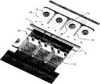
Fig. 4 illustrates according to ink jet-print head of the present invention and cut top view open near nozzle array;
Fig. 5 A-5H illustrates the process that forms ink jet-print head according to the present invention, and described printhead has at embodiment shown in Figure 4 and passes chamber and the nozzle plate that forms with a kind of inorganic layer (or inorganic material) in the cross section of cross section A-A;
Fig. 6 illustrates the cutaway view according to a cross section of printhead of the present invention;
Fig. 7 illustrates the substrate 1 according to the array of rib of the present invention; And
Fig. 8 illustrates the end according to the ink chamber zone of printhead of the present invention.
The specific embodiment
The description that provides will be especially at form according to those parts of the part of equipment of the present invention (or device) or more directly with those parts according to equipment collaboration work of the present invention.Should be appreciated that those parts that do not illustrate particularly or describe can be got various ways well-known to those skilled in the art.
As described below such, the invention provides a kind of be used for the being formed for nozzle plate of liquid drop ejector (liquid droplet ejection apparatus) and the method for chamber.The most familiar in these devices is the printhead that is used as in the ink-jet print system.Many other application also occurred, these are used to adopt with ink jet-print head and similarly install, however described device emission liquid rather than ink, and these liquid need measure subtly, and deposit these liquid with very high spatial accuracy.To use these two terms of ink-jet and liquid drop ejector here interchangeably.The present invention who describes below also is provided for the improved chamber and the nozzle plate of liquid drop ejector.
Fig. 2 is the schematic diagram that is combined with the ink-jet print system of the liquid drop ejector of making according to the present invention.Described system comprises image data source 12, and described image data source provides the signal that is received by controller 14, as the order of printed droplets.Controller 14 outputs to electrical pulse source 16 with signal.Electrical pulse source 16 and then produce comprises the voltage signal of electrical energy pulse (or is made up of it), and described voltage signal is applied on the interior electrothermal heater 2 of ink jet-print head 20.Clock 16 can separate with printhead.In a preferred embodiment, clock 16 is integrated in the printhead.Ink jet-print head 20 comprises nozzle array 18 and the electrothermal piece 2 that is associated.Described printhead is arrived with ink feed in ink storage chamber 90.Electrical energy pulse causes liquid to pass through the injection of nozzle 18, is associated with the electrothermal heater of pulse, launches drop 50, and described drop drops on the recording medium 100.
Fig. 3 illustrates the schematic top view of the ink jet-print head 20 of Fig. 2.In one embodiment, nozzle 18 is arranged by two put.Make the nozzle biasing among each row, differentiate with the npi that realizes printhead.In other embodiments, the nozzle array among every row can be staggered, perhaps the pattern of nozzle can be arranged to a two-dimensional array.Ink jet-print head of the present invention can comprise 640 bigger arrays of nozzle of a ratio, and can expand.The MOSFET power drill/driver that is used for each heater and the CMOS control logic part that schematically show in Fig. 3 also are comprised in the printhead.Must protect these circuits not contact in the whole length of life of ink jet-print head with ink.Realize that with printhead the joint sheet (or key mat (bondpads)) 19 of electric connection is arranged on the periphery of printhead with being used for.
Fig. 4 illustrates near the top view in the cross section (or part) of ink jet-print head 20 nozzle array.Each nozzle 18 is positioned at the top of corresponding electrothermal heater.Also can see chamber wall 38 by the top, described chamber wall is determined and is used for the right chamber of each heater/nozzle; Can also see be used as filter and drop spray and the process that refills in the column array 46 of control fluid impedance; And the centre bearing zone walls 56 of determining centre bearing zone 8.Separate supporting structure 57 in described centre bearing zone walls, separate the top that supporting structure is set in place the rib structure in described substrate described.
In Fig. 5 A-H, the cutaway perspective form of passing the A-A cross section with embodiment shown in Figure 4 shows the process that forms the ink jet-print head that has the chamber that constitutes with inorganic layer and nozzle plate, profile is arranged to the mentioned nozzle area that show two rows.Fig. 5 A illustrates chamber and forms preceding substrate, has wherein formed driver and control circuit (not shown) in substrate 1.Also show film stack 22, described film stack comprises electrothermal heater 2.In one embodiment, substrate 1 is a silicon.In other embodiments, substrate 1 is one of following material: polysilicon, quartz, stainless steel, perhaps polyimides.
Thermal shield (or thermal barrier) 24 can be made of a variety of materials, such as the silica of deposition, field oxide (field oxide), glass (BPSG) and nitrogen oxide.This one deck has been realized heat insulation and the electric insulation between electric heating heating member 2 and the substrate 1.It on the end face of thermal shield 24 resistance heated (or heater) layer 26.In this embodiment, this resistance heating layer is made by the tantalum silicon nitride material of ternary.
On the end face of resistance heating layer 26, deposit conductive layer 28.Described conductive layer 28 by the metal that typically in MOS makes, adopts such as aluminium or comprise copper and/or the aluminium alloy of silicon is made.Make described conductive layer 28 form pattern and described conductive layer is carried out etching, to form conductive trace (or conductive trace), described conductive trace is connected on the control circuit of producing on the ink jet-print head 20, and described conductive layer also forms electrothermal heater 2.
As shown in Fig. 5 A, then deposit the passivation layer 30 of insulation.The passivation layer 30 of this insulation can be by silicon nitride, silica and carborundum, and perhaps any combination of these materials is made.End face at the passivation layer 30 of described insulation deposits protective layer 32.Described protective layer 32 is by tantalum, and the combination of the nitride of tantalum silicon or two kinds of materials is made.This one deck protection electric heater makes it not touch ink.Pass the film stack and etch two ink feed mouths 6 up to substrate 1 downwards, one at each row's nozzle.Chamber centre bearing zone 8 is between two ink feed mouths.In the process of the lower section (or part) that forms the centre bearing zone 8 between the ink feed mouth, also use some layer or whole film stack.
Fig. 5 B illustrates one embodiment of the present of invention, wherein is coated with or has applied a kind of organic matter material 48.In one embodiment, this organic matter material 48 be can not optical imagery polyimides.Selected polyimides is that a kind of to have thermal coefficient of expansion little, the performance of good complanation, and do not add the material of any ratio of component such as photoactivation component.A kind of such polyimides is the PI2611 from HD Microsystems company.Organic matter material 48 is determined the height of chamber.Toast the thickness of (imidization bake) described afterwards organic matter material 48 at scope 8-16 micron in imidization.In this embodiment, highly be the 12-14 micron.The imidization baking lasts one hour under the temperature between 300-400 ℃.In this embodiment, temperature is chosen to higher or equal follow-up treatment temperature than follow-up treatment temperature.
Fig. 5 C illustrates the hard mask 52 that is deposited on the organic matter material 48.Described hard mask 52 is the silicon nitrides by PECVD deposition, silica, or the aluminium by sputtering sedimentation.In a preferred embodiment, described hard mask 52 is silicon nitrides.Coating forms the hard mask of protective layer 51, and makes described hard mask form pattern.By dry etching for example adopt a kind of be used for nitride with the fluorine be the base plasma etching with described design transfer to described hard mask 52.
As shown in Fig. 5 D, adopt subsequently a kind of low-pressure high-density plasma such as with oxygen as the inductively coupled plasma of main gas component with the design transfer of hard mask 52 in organic matter material 48.In this etching process, remove the hard mask that forms protective layer 51.The pattern that is transferred will be formed for the perforate of chamber wall 38, filter column 46 (not shown), and centre bearing zone walls 56.The width of these structures (or structure or feature) may be different.In one embodiment, chamber wall is that the 8-10 micron is wide.Macroion density low pressure plasma etching can produce very high etch rate, has very vertical etching molded lines, presents minimum undercutting (undercut), thereby can obtain accurate chamber geometry shape.Adopt dry etching or wet etching (this step is not shown in the drawings) to remove described hard mask 52 subsequently.Organic matter material 48 is divided into three zones: protect suprabasil circuit and the polyimide passivation zone 40 of structure support is provided for nozzle plate in the zone of leaving chamber; The polyimides center-fed supporting member 41 of structure support is provided for nozzle plate above the ink feed mouth; And the polyimides sacrifice region 54 that forms the zone that the printhead ink inside will place.
In Fig. 5 E, deposition inorganic material layer forms inorganic matter chamber 34 and top liner layer 42.Described inorganic material layer is a silicon nitride, carborundum or silica.In a preferred embodiment, the chemical vapour desposition (PECVD) of using plasma enhancing is at 300-400 ℃ of deposit silica.Adopt polyimide sacrificial layer 54 to make this high temperature deposition become possibility, and this is impossible in prior art, adopts protective layer as sacrifice layer in prior art.This causes depositing the material of the higher higher quality of density, and described material will more can be resisted ink, and better adhesive property is arranged.Before deposition, also can carry out of short duration ise, bonding with further improvement.The inorganic matter chamber 34 of silica has been given hydrophilic chamber, and described hydrophilic chamber is compared with the more hydrophobic polymer chamber of prior art and provided easier filling ink, and lessly may form air bubble.The thickness of the inorganic material of the nozzle plate 44 of formation top liner layer 42 and inorganic matter chamber 34 preferably is the 7-8 micron between 3 microns and 10 microns.In one embodiment, the thickness of described nozzle plate is littler than the thickness of organic matter material 48.Typically, in the present embodiment, this deposition technique has realized that for chamber wall 38 sidewall of 50-60% covers, and this depends on the perforate of chamber wall.
It is that basic plasma is dry-etched in the nozzle 18 that forms in the nozzle plate 44 that Fig. 5 F illustrates by light protection layer being formed pattern and adopting with the fluorine.This etching process produces the nozzle of Sidewall angles greater than 84 degree in 7 microns inorganic layer.In this etching process, the inorganic matter backing layer on the joint sheet is removed, made up to joint sheet 19 and all open wide.
Alternatively substrate 1 is thinned to the thickness of 300-400 micron, and goes up the formation pattern overleaf with protective layer.In Fig. 5 G, as be in the art well-known, adopt deep reaction ion etching that pattern etch is penetrated silicon base 1 with the Bosch process, in substrate, form ink feed mouth 3.
As shown in Fig. 5 H, adopt the hyperbaric oxygen plasma to pass the back side of substrate and the areas of polyimide that nozzle (plate) is removed sacrifice.The ink chamber 36 that the removing of the polyimide layer of sacrificing causes inorganic matter and the formation of ink feed mouth 6.Polyimide passivation layer 40 is retained on the wafer (wafer), with protection circuit (or circuit).Also keep polyimides center-fed supporting member 41.The border of passivation layer 40 and center-fed supporting member 41 is all determined by chamber wall, thereby they can not contact with liquid when in chamber 36 liquid being arranged.
Fig. 6 illustrates the cutaway view of printhead, and wherein the part of nozzle plate has been removed.A kind of inorganic material layer forms chamber wall 38.As shown in the figure, each chamber wall includes gap 72.We have found that: it is important keeping this gap when forming chamber wall 38.If the deposition of inorganic material layer proceeds to the degree that the gap is connected, be connected at the top typically, the additional stress that this connection produces can cause crackle in the inorganic material layer.In order to form this gap, it is big or equal this thickness that the perforate that will be used for chamber wall before deposition inorganic material layer is designed to thickness than nozzle plate 44.Like this, the width that gets up of two wall portions and combinations of gaps is bigger than the thickness of nozzle plate.In order to make the interval between the chamber reach minimum, the chamber wall between each liquid chamber does not comprise any organic matter material.
The inorganic material layer also forms column 46.In this embodiment, the passivation layer that they pass protective layer and insulation stretches, and is attached in the substrate 1.In other embodiments, these filtrations (device) column 46 can be overhang out by top nozzle plate 44.
Fig. 6 also illustrates the part cutaway view in centre bearing zone 8.Described centre bearing zone comprises an organic matter material area that is positioned at described substrate top, and described zone can not contact with ink when in printhead ink being arranged.In one embodiment, described centre bearing zone comprises polyimides or is made of it that described polyimides portion boundary is determined in inorganic matter centre bearing zone that overhangs out above liquid supply ink feed mouth 3.Ink feed mouth 6 is in each side in described centre bearing zone, and described feed port is above the ink feed mouth 3 of the row of two on the opposite sides of ink feed being presented delivery member to liquid ink nozzle 18.
The rib 74 of that part of substrate 1 formation that is arranged in ink feed mouth 3 also is shown in Fig. 6.Have a plurality of ribs along described ink feed mouth.These ribs provide mechanical strength for printhead.
Fig. 7 illustrates substrate 1 together with the rib array 74 in ink feed mouth 3.The ink feed mouth 3 of the length in substrate 1 has reduced the mechanical strength of substrate, makes the substrate ratio be easier to owing to distortion is damaged.Cross ink feed mouth interpolation rib 74 and reduced this weakness widely.The employing interval can obtain suitable intensity less than a plurality of ribs of 1.5 millimeters.Along with the length increase of printhead, the improvement of this mechanical strength becomes more and more important.The application of rib makes that printhead is extended to big nozzle array becomes possibility.
Along the ink feed mouth artefact (or pseudomorphism (artifacts)) that rib may cause printing is set, this is because lower in the ability of presenting of the ink chamber at the position of adjacent ribs.We have found that: width less than 40 microns rib without any such artefact.Alternatively, for the purpose of intensity with owing to etch the length-width ratio of rib, we have found that: the width of rib should be than 10 microns big, and rib (width) should be connected on the centre bearing zone.In a preferred embodiment, the width of rib is the 15-25 micron.These width are to measure on the back side of substrate.Because it not exclusively is anisotropic passing the etching of described substrate, so will be littler than this numerical value at the width of the rib in centre bearing zone.
Return the past with reference to figure 6, touch with ribbed joint in centre bearing zone 8, and described centre bearing zone also has separate supporting structure 57 on rib.We have found that: do not separate structure if add this, crackle may appear in the bottom of described central support structure 8.If this occurs, during the release steps of the polyimides of sacrificing, the polyimides in described centre bearing zone may be under attack.Add this and separate structure 57 and increased a stress release in described centre bearing zone map, this will eliminate above-mentioned possibility.
The outside of chamber above other zone of device is thick polyimide passivation layer 40 and top liner layer 42.The inorganic layer 34 of deposition not only forms nozzle plate 44 but also form top liner layer 42.The device circuit of the join protection of passivation layer 40 and top liner layer 42 on ink jet-print head 20 not can owing to ambient influnence with contact and variation with ink.
Fig. 8 illustrates an end in the ink chamber zone of printhead 20.In one embodiment, the described chamber wall that is close to polyimide passivation zone 40 comprises the projection 76 that stretches towards polyimide passivation zone 40.These projections are used from stress release (part) effect of chamber wall.We have found that: radius of curvature can reduce the possibility that crackle appears in nozzle plate 44 greater than such projection of 5 microns, and radius of curvature can increase the possibility that crackle occurs less than 5 microns projection.
In a special embodiment, inorganic layer 34 forms ink chamber 36, corresponding electrothermal piece 2 heating inks in described ink chamber, and inorganic layer 34 formation nozzles 18, and heated ink passes described nozzle ejection and goes out, and forms ink droplet 50.The operation of described device is as follows.An electric pulse is applied on the electrothermal heater 2.Described heating pulse causes bubble nucleation in chamber, and it is grown up, and will discharge by nozzle 18 with the form of drop from the ink of ink chamber 36, and also promote ink towards the ink feed mouth backward, makes the major part of ink chamber no longer include ink.Refill or the injection frequency of described device that has been full of the used time restriction of ink chamber 36.Hydrophobic chamber wall makes the time that increase refills can not be full of chamber fully before the injection pulse next time.This so cause and eject less and out-of-alignment drop, perhaps in the worst case, without any drop.Hydrophobic chamber wall also can be more prone to retain bubble in the process that refills.The bubble that retains in the chamber of ink feed mouth can make the injection variation of drop equally.The organic material that adopts in prior art is more hydrophobic than the inorganic backing layer that adopts in the present invention.The present invention has the inorganic material of higher surface energy freely to regulate chamber by adopting for the ink that with water is base, and it is hydrophilic that chamber is become.
We also have been found that: the silicon nitride and the silica that form the high-temperature plasma deposition of chamber wall 38 are that basic material can bond on suprabasil protective layer and the passivation layer better than with epoxy resin.Therefore, described device is firmer, can not occur delamination for a long time.
By top described, it will be appreciated that the present invention is the invention that is suitable for obtaining all purposes well.For the purpose of illustration and description has provided foregoing description to the preferred embodiments of the present invention.Do not wish that it is exhaustively, perhaps limit the invention to disclosed strict form.Any improvement and variation all are possible, and those skilled in the art will appreciate that this point according to top content.For example, the invention is not restricted to form the chamber of thermal bubble jet device, and comprise and be formed for the chamber of other droplet discharge method such as thermal actuator or electrostatic actuator or piezoelectric actuated liquid device.These additional embodiment belong in the scope of appending claims.
The parts catalogue
1 substrate
2 electric heaters (or electric calorifie installation)
3 ink feeds (mouth)
4 chambers
5 can form the resin of pattern with optical means
6 ink feed mouths
8 centre bearing zones
10 ink-jet print systems
12 image data source
14 controllers
16 clocks
18 nozzles
19 joint sheets
20 ink jet-print heads
22 film stacks
24 thermal shields
26 resistance heated (device) layer
28 conductive layers
The passivation layer of 30 insulation
32 protective layers
34 inorganic matter chambers
36 chambers
38 chamber sidewall
40 polyimide passivation layer
41 polyimides center-fed supporting members
42 top liner layers
44 nozzle plates
46 columns
48 organic matter materials
50 ink droplets
51 form the hard mask of resistive layer
52 hard masks
54 areas of polyimide of sacrificing
56 centre bearing zone walls
57 separate supporting structure
72 gaps
74 ribs
76 projections
90 inks storage chamber
100 recording mediums
Claims (23)
1. liquid ejector, it comprises:
Substrate, a plurality of parts of described substrate form liquid supplying apparatus;
A plurality of liquid chambers, each described liquid chamber is positioned on the described substrate, and comprise nozzle plate and chamber wall, described nozzle plate and described chamber wall comprise a kind of inorganic material, the inorganic material of described nozzle plate and described chamber wall can contact with liquid when having liquid in each described liquid chamber, described nozzle plate comprises top surface, described chamber wall comprises two wall portions of inorganic material system, described two wall portions are spaced apart from each other, make to have the gap between described two wall portions, described gap is stretched over the described top surface of described nozzle plate; And
Be positioned at the organic material zone on the described substrate, described organic material zone is arranged so that with respect to described nozzle plate and described chamber wall described organic material zone can not contact with liquid when having liquid in each described liquid chamber, wherein, form the border in described organic material zone by the chamber wall of the liquid chamber of the vicinity on the opposite flank that is positioned at described liquid supplying apparatus.
2. according to the described liquid ejector of claim 1, it is characterized in that the organic material in described organic material zone is a polyimides.
3. according to the described liquid ejector of claim 1, it is characterized in that described nozzle plate comprises certain thickness, described organic material zone comprises certain thickness, and wherein, the thickness of described nozzle plate is littler than the thickness in described organic material zone.
4. according to the described liquid ejector of claim 3, it is characterized in that the thickness of described nozzle plate is between 3 microns to 10 microns, and the thickness in described organic material zone is between 8 microns to 16 microns.
5. according to the described liquid ejector of claim 1, it is characterized in that the inorganic material of described nozzle plate is identical inorganic material with the inorganic material of described chamber wall.
6. according to the described liquid ejector of claim 5, it is characterized in that described inorganic material is a silica.
7. according to the described liquid ejector of claim 1, it is characterized in that, between the adjacent liquid chamber on the same side at described liquid supplying apparatus without any the organic material zone.
8. according to the described liquid ejector of claim 1, it is characterized in that at least one zone in the described organic material zone that is defined by the chamber wall of contiguous liquid chamber overhangs out on described liquid supplying apparatus.
9. according to the described liquid ejector of claim 1, it is characterized in that described liquid supplying apparatus comprises a plurality of liquid feed port, rib separates adjacent liquid feed port, and described rib is the part of substrate.
10. according to the described liquid ejector of claim 9, it is characterized in that at least one zone in the described organic material zone that is defined by the chamber wall of contiguous liquid chamber is touched with described ribbed joint.
11. according to the described liquid ejector of claim 9, the width of described rib is less than 40 microns.
12. a liquid ejector, it comprises:
Substrate, a plurality of parts of described substrate form liquid supplying apparatus;
A plurality of liquid chambers, each described liquid chamber is positioned on the described substrate, and comprise nozzle plate and chamber wall, described nozzle plate and described chamber wall comprise a kind of inorganic material, the inorganic material of described nozzle plate and described chamber wall can contact with liquid when having liquid in each described liquid chamber, described nozzle plate comprises top surface, described chamber wall comprises two wall portions of inorganic material system, described two wall portions are spaced apart from each other, make to have the gap between described two wall portions, described gap is stretched over the described top surface of described nozzle plate; And
Be positioned at the organic material zone on the described substrate, described organic material zone is arranged so that with respect to described nozzle plate and described chamber wall described organic material zone can not contact with liquid when having liquid in each described liquid chamber, wherein, between the adjacent liquid chamber on the same side at described liquid supplying apparatus without any the organic material zone.
13., it is characterized in that at least one in a plurality of liquid chambers comprises a plurality of chamber walls according to the described liquid ejector of claim 12, wherein, one of described a plurality of chamber walls comprise the projection that stretches towards organic material.
14., it is characterized in that the radius of curvature of described projection is greater than 5 microns according to the described liquid ejector of claim 13.
15., it is characterized in that at least one in described a plurality of liquid chambers comprises a plurality of chamber walls according to the described liquid ejector of claim 12, wherein, a chamber wall intersects at bight and another chamber wall of radius of curvature greater than 5 microns.
16. according to the described liquid ejector of claim 12, it is characterized in that, each liquid chamber comprises at the inorganic material layer between described substrate and described nozzle plate on the described substrate, described inorganic material layer can contact with liquid when having liquid in each liquid chamber, wherein, described inorganic material layer contacts with the part of the inorganic material of the chamber wall of each liquid chamber.
17., it is characterized in that described nozzle plate comprises certain thickness according to the described liquid ejector of claim 12, and described organic material zone comprises certain thickness, wherein, the thickness of described nozzle plate is littler than the thickness in described organic material zone.
18. a liquid ejector, it comprises:
Substrate;
Be used for the liquid chamber of receiving fluids, described liquid chamber is positioned on the described substrate, and comprise nozzle plate and chamber wall, described nozzle plate and described chamber wall comprise a kind of inorganic material, the inorganic material of described nozzle plate and described chamber wall can contact with liquid when having liquid in liquid chamber, described nozzle plate comprises top surface, described chamber wall comprises two wall portions of inorganic material, described two wall portions are spaced apart from each other, make to have the gap between described two wall portions, described gap is stretched over the described top surface of described nozzle plate; And
Be positioned at the organic material zone on the described substrate, described organic material zone is arranged so that with respect to described nozzle plate and described chamber wall described organic material zone can not contact with liquid when having liquid in each liquid chamber.
19. according to the described liquid ejector of claim 18, it is characterized in that described two wall portions and described gap have the width that combines, described nozzle plate has certain thickness, wherein, the described width that combines in described two wall portions and described gap is bigger than the thickness of described nozzle plate.
20. a method of making liquid ejector, it comprises:
Substrate is provided; And
In described substrate, form a plurality of liquid chambers by following steps:
A kind of organic material is set on described substrate;
Make described organic material form pattern, be used for the position of the chamber wall of each described liquid chamber with generation;
Be formed for the nozzle plate and the chamber wall of each liquid chamber by deposition inorganic material on the organic material that forms pattern, make that the inorganic material of described nozzle plate and described chamber wall can contact with liquid when having liquid in each liquid chamber, wherein, described chamber wall comprises two wall portions of inorganic material system, described two wall portions are spaced apart from each other, make to have the gap between described two wall portions, described gap is stretched over the top surface of described nozzle plate; And
Remove the part of the organic material that forms pattern, thereby the organic material zone that retains is defined by the chamber wall of contiguous liquid chamber, wherein, described organic material zone can not contact with liquid when having liquid in each liquid chamber.
21. in accordance with the method for claim 20, it is characterized in that described method also comprises:
Passing for each liquid chamber is that common substrate forms liquid supplying apparatus, wherein, defines described organic material zone by the chamber wall of the liquid chamber of the vicinity on the opposite flank that is positioned at described liquid supplying apparatus.
22. in accordance with the method for claim 20, it is characterized in that described method also comprises:
Passing for each liquid chamber is that common substrate forms liquid supplying apparatus, wherein, between the adjacent liquid chamber on the same side at described liquid supplying apparatus without any the organic material zone.
23. in accordance with the method for claim 20, it is characterized in that, provide substrate to be included in the described liquid chamber of formation and adopt film deposition techniques before.
Applications Claiming Priority (3)
| Application Number | Priority Date | Filing Date | Title |
|---|---|---|---|
| US11/609,365 | 2006-12-12 | ||
| US11/609,365 US7600856B2 (en) | 2006-12-12 | 2006-12-12 | Liquid ejector having improved chamber walls |
| PCT/US2007/024836 WO2008073242A2 (en) | 2006-12-12 | 2007-12-04 | Liquid ejector having improved chamber walls |
Publications (2)
| Publication Number | Publication Date |
|---|---|
| CN101557938A CN101557938A (en) | 2009-10-14 |
| CN101557938B true CN101557938B (en) | 2011-08-10 |
Family
ID=39133827
Family Applications (1)
| Application Number | Title | Priority Date | Filing Date |
|---|---|---|---|
| CN2007800460643A Expired - Fee Related CN101557938B (en) | 2006-12-12 | 2007-12-04 | Liquid ejector having improved chamber walls and preparing method thereof |
Country Status (5)
| Country | Link |
|---|---|
| US (1) | US7600856B2 (en) |
| EP (1) | EP2089231A2 (en) |
| JP (1) | JP5139444B2 (en) |
| CN (1) | CN101557938B (en) |
| WO (1) | WO2008073242A2 (en) |
Families Citing this family (36)
| Publication number | Priority date | Publication date | Assignee | Title |
|---|---|---|---|---|
| US7914127B2 (en) * | 2005-05-31 | 2011-03-29 | Telecom Italia S.P.A. | Nozzle plate for an ink jet print head comprising stress relieving elements |
| US7938974B2 (en) * | 2007-03-12 | 2011-05-10 | Silverbrook Research Pty Ltd | Method of fabricating printhead using metal film for protecting hydrophobic ink ejection face |
| US7669967B2 (en) | 2007-03-12 | 2010-03-02 | Silverbrook Research Pty Ltd | Printhead having hydrophobic polymer coated on ink ejection face |
| US7605009B2 (en) * | 2007-03-12 | 2009-10-20 | Silverbrook Research Pty Ltd | Method of fabrication MEMS integrated circuits |
| US7794613B2 (en) * | 2007-03-12 | 2010-09-14 | Silverbrook Research Pty Ltd | Method of fabricating printhead having hydrophobic ink ejection face |
| US8012363B2 (en) * | 2007-11-29 | 2011-09-06 | Silverbrook Research Pty Ltd | Metal film protection during printhead fabrication with minimum number of MEMS processing steps |
| US20090233386A1 (en) * | 2008-03-12 | 2009-09-17 | Yimin Guan | Method for forming an ink jetting device |
| US8173030B2 (en) | 2008-09-30 | 2012-05-08 | Eastman Kodak Company | Liquid drop ejector having self-aligned hole |
| US8110117B2 (en) * | 2008-12-31 | 2012-02-07 | Stmicroelectronics, Inc. | Method to form a recess for a microfluidic device |
| JP5359642B2 (en) * | 2009-07-22 | 2013-12-04 | 東京エレクトロン株式会社 | Deposition method |
| US8267501B2 (en) * | 2009-08-20 | 2012-09-18 | Eastman Kodak Company | Drop ejector having multi-lobed nozzle |
| US20110043555A1 (en) * | 2009-08-20 | 2011-02-24 | Yonglin Xie | Drop ejection method through multi-lobed nozzle |
| US8205338B2 (en) * | 2009-08-20 | 2012-06-26 | Eastman Kodak Company | Method of making a multi-lobed nozzle |
| US8449086B2 (en) | 2011-03-30 | 2013-05-28 | Eastman Kodak Company | Inkjet chamber and inlets for circulating flow |
| US9403365B2 (en) * | 2011-04-29 | 2016-08-02 | Funai Electric Co., Ltd. | Method for fabricating fluid ejection device |
| US20120274707A1 (en) * | 2011-04-29 | 2012-11-01 | Xiaorong Cai | Ejection devices for inkjet printers and method for fabricating ejection devices |
| US20130186301A1 (en) | 2012-01-24 | 2013-07-25 | Thomas Nelson Blanton | Ink having antibacterial and antifungal protection |
| US20130189499A1 (en) | 2012-01-24 | 2013-07-25 | Thomas Nelson Blanton | Antibacterial and antifungal protection for ink jet image |
| US20130083126A1 (en) * | 2011-09-30 | 2013-04-04 | Emmanuel K. Dokyi | Liquid ejection device with planarized nozzle plate |
| US20130082028A1 (en) * | 2011-09-30 | 2013-04-04 | Emmanuel K. Dokyi | Forming a planar film over microfluidic device openings |
| US20130237661A1 (en) | 2011-12-22 | 2013-09-12 | Thomas B. Brust | Inkjet ink composition |
| JP6041527B2 (en) | 2012-05-16 | 2016-12-07 | キヤノン株式会社 | Liquid discharge head |
| JP5740371B2 (en) * | 2012-09-11 | 2015-06-24 | 東芝テック株式会社 | Inkjet head |
| JP6095315B2 (en) | 2012-10-02 | 2017-03-15 | キヤノン株式会社 | Method for manufacturing liquid discharge head |
| JP5972139B2 (en) * | 2012-10-10 | 2016-08-17 | キヤノン株式会社 | Method for manufacturing liquid discharge head and liquid discharge head |
| JP6116198B2 (en) | 2012-11-15 | 2017-04-19 | キヤノン株式会社 | Method for manufacturing liquid discharge head |
| JP2014188656A (en) * | 2013-03-28 | 2014-10-06 | Tokyo Electron Ltd | Manufacturing method of hollow structure |
| US9199460B2 (en) * | 2013-06-28 | 2015-12-01 | Hewlett-Packard Development Company, L.P. | Apparatuses including a plate having a recess and a corresponding protrusion to define a chamber |
| JP6234095B2 (en) | 2013-07-16 | 2017-11-22 | キヤノン株式会社 | Liquid discharge head and manufacturing method thereof |
| JP6214284B2 (en) | 2013-09-02 | 2017-10-18 | キヤノン株式会社 | Liquid discharge head and manufacturing method thereof |
| JP6202987B2 (en) * | 2013-10-30 | 2017-09-27 | キヤノン株式会社 | Liquid discharge head and manufacturing method thereof |
| CN105599452A (en) * | 2016-03-03 | 2016-05-25 | 中国科学院苏州纳米技术与纳米仿生研究所 | Multilayer material orifice structure and printer |
| CN105667090A (en) * | 2016-03-03 | 2016-06-15 | 中国科学院苏州纳米技术与纳米仿生研究所 | Flat film layer spray orifice structure and ink-jet printer |
| WO2019074683A1 (en) | 2017-10-11 | 2019-04-18 | Eastman Kodak Company | Aqueous inkjet ink compositions and ink sets |
| CN107757127B (en) * | 2017-10-30 | 2023-05-26 | 苏州工业园区纳米产业技术研究院有限公司 | Nozzle structure, preparation method of nozzle structure and micro-electromechanical ink-jet printing head |
| US11559987B2 (en) | 2019-01-31 | 2023-01-24 | Hewlett-Packard Development Company, L.P. | Fluidic die with surface condition monitoring |
Citations (4)
| Publication number | Priority date | Publication date | Assignee | Title |
|---|---|---|---|---|
| EP0904939A2 (en) * | 1997-09-30 | 1999-03-31 | Canon Kabushiki Kaisha | Ink jet head, method of manufacturing such ink jet head, and ink jet apparatus provided with such ink jet head |
| US6382777B1 (en) * | 1998-06-19 | 2002-05-07 | Canon Kabushiki Kaisha | Liquid jet recording head |
| US6644786B1 (en) * | 2002-07-08 | 2003-11-11 | Eastman Kodak Company | Method of manufacturing a thermally actuated liquid control device |
| EP1366906A1 (en) * | 2002-05-31 | 2003-12-03 | Hewlett-Packard Company | Chamber having a protective layer |
Family Cites Families (15)
| Publication number | Priority date | Publication date | Assignee | Title |
|---|---|---|---|---|
| JP3143307B2 (en) | 1993-02-03 | 2001-03-07 | キヤノン株式会社 | Method of manufacturing ink jet recording head |
| US6234608B1 (en) | 1997-06-05 | 2001-05-22 | Xerox Corporation | Magnetically actuated ink jet printing device |
| US6331258B1 (en) | 1997-07-15 | 2001-12-18 | Silverbrook Research Pty Ltd | Method of manufacture of a buckle plate ink jet printer |
| US7401901B2 (en) | 1997-07-15 | 2008-07-22 | Silverbrook Research Pty Ltd | Inkjet printhead having nozzle plate supported by encapsulated photoresist |
| US6022482A (en) | 1997-08-04 | 2000-02-08 | Xerox Corporation | Monolithic ink jet printhead |
| JP3619036B2 (en) | 1997-12-05 | 2005-02-09 | キヤノン株式会社 | Method for manufacturing ink jet recording head |
| US6569343B1 (en) | 1999-07-02 | 2003-05-27 | Canon Kabushiki Kaisha | Method for producing liquid discharge head, liquid discharge head, head cartridge, liquid discharging recording apparatus, method for producing silicon plate and silicon plate |
| US6474795B1 (en) | 1999-12-21 | 2002-11-05 | Eastman Kodak Company | Continuous ink jet printer with micro-valve deflection mechanism and method of controlling same |
| US6482574B1 (en) | 2000-04-20 | 2002-11-19 | Hewlett-Packard Co. | Droplet plate architecture in ink-jet printheads |
| US6561627B2 (en) | 2000-11-30 | 2003-05-13 | Eastman Kodak Company | Thermal actuator |
| US6750290B2 (en) | 2001-04-19 | 2004-06-15 | Canon Kabushiki Kaisha | Epoxy resin composition, method of improving surface of substrate, ink jet recording head and ink jet recording apparatus |
| US6555480B2 (en) | 2001-07-31 | 2003-04-29 | Hewlett-Packard Development Company, L.P. | Substrate with fluidic channel and method of manufacturing |
| US6626523B2 (en) * | 2001-10-31 | 2003-09-30 | Hewlett-Packard Development Company, Lp. | Printhead having a thin film membrane with a floating section |
| ITTO20021099A1 (en) * | 2002-12-19 | 2004-06-20 | Olivetti I Jet Spa | PROTECTIVE COATING PROCESS OF HYDRAULIC MICRO CIRCUITS COMPARED TO AGGRESSIVE LIQUIDS. PARTICULARLY FOR AN INK-JET PRINT HEAD. |
| KR100570822B1 (en) * | 2004-05-11 | 2006-04-12 | 삼성전자주식회사 | method for fabricating ink jet head and ink jet head fabricated thereby |
-
2006
- 2006-12-12 US US11/609,365 patent/US7600856B2/en not_active Expired - Fee Related
-
2007
- 2007-12-04 EP EP07853231A patent/EP2089231A2/en not_active Withdrawn
- 2007-12-04 JP JP2009541309A patent/JP5139444B2/en not_active Expired - Fee Related
- 2007-12-04 CN CN2007800460643A patent/CN101557938B/en not_active Expired - Fee Related
- 2007-12-04 WO PCT/US2007/024836 patent/WO2008073242A2/en active Application Filing
Patent Citations (4)
| Publication number | Priority date | Publication date | Assignee | Title |
|---|---|---|---|---|
| EP0904939A2 (en) * | 1997-09-30 | 1999-03-31 | Canon Kabushiki Kaisha | Ink jet head, method of manufacturing such ink jet head, and ink jet apparatus provided with such ink jet head |
| US6382777B1 (en) * | 1998-06-19 | 2002-05-07 | Canon Kabushiki Kaisha | Liquid jet recording head |
| EP1366906A1 (en) * | 2002-05-31 | 2003-12-03 | Hewlett-Packard Company | Chamber having a protective layer |
| US6644786B1 (en) * | 2002-07-08 | 2003-11-11 | Eastman Kodak Company | Method of manufacturing a thermally actuated liquid control device |
Also Published As
| Publication number | Publication date |
|---|---|
| CN101557938A (en) | 2009-10-14 |
| US7600856B2 (en) | 2009-10-13 |
| US20080136867A1 (en) | 2008-06-12 |
| EP2089231A2 (en) | 2009-08-19 |
| JP5139444B2 (en) | 2013-02-06 |
| WO2008073242A3 (en) | 2008-08-14 |
| JP2010512262A (en) | 2010-04-22 |
| WO2008073242A2 (en) | 2008-06-19 |
Similar Documents
| Publication | Publication Date | Title |
|---|---|---|
| CN101557938B (en) | Liquid ejector having improved chamber walls and preparing method thereof | |
| CN101557939B (en) | Liquid drop ejector having improved liquid chamber and manufacture method | |
| CN1325264C (en) | Ink jet printhead chip with predetermined micro-electromechanical systems height | |
| US6158846A (en) | Forming refill for monolithic inkjet printhead | |
| US6682874B2 (en) | Droplet plate architecture | |
| JP2010534580A (en) | Heating element | |
| JP2008049531A (en) | Inkjet recording head | |
| US6649074B2 (en) | Bubble-jet type ink-jet print head and manufacturing method thereof | |
| US20070052759A1 (en) | Inkjet printhead and method of manufacturing the same | |
| JP2004025862A (en) | Inkjet printer head and production method therefor | |
| KR20100011652A (en) | Inkjet printhead and method of manufacturing the same | |
| KR100446634B1 (en) | Inkjet printhead and manufacturing method thereof | |
| JP5294657B2 (en) | Inkjet recording head | |
| KR100965665B1 (en) | Low loss electrode connection for inkjet printhead | |
| JP4667008B2 (en) | Method for manufacturing ink jet recording head | |
| JP2007168115A (en) | Inkjet head and its manufacturing process | |
| TWI232802B (en) | High density jetting apparatus | |
| KR100519765B1 (en) | Inkjet printhead and manufacturing method the same | |
| KR100644706B1 (en) | Inkjet printhead and method of manufacturing the same | |
| KR100421027B1 (en) | Inkjet printhead and manufacturing method thereof | |
| JP2007283549A (en) | Inkjet recording head and method for manufacturing the same | |
| KR100400228B1 (en) | Inkjet printhead and manufacturing method thereof |
Legal Events
| Date | Code | Title | Description |
|---|---|---|---|
| C06 | Publication | ||
| PB01 | Publication | ||
| C10 | Entry into substantive examination | ||
| SE01 | Entry into force of request for substantive examination | ||
| C14 | Grant of patent or utility model | ||
| GR01 | Patent grant | ||
| C17 | Cessation of patent right | ||
| CF01 | Termination of patent right due to non-payment of annual fee |
Granted publication date: 20110810 Termination date: 20131204 |