CN101538984A - Inverted hook type latch locking structure - Google Patents
Inverted hook type latch locking structure Download PDFInfo
- Publication number
- CN101538984A CN101538984A CN200910097753A CN200910097753A CN101538984A CN 101538984 A CN101538984 A CN 101538984A CN 200910097753 A CN200910097753 A CN 200910097753A CN 200910097753 A CN200910097753 A CN 200910097753A CN 101538984 A CN101538984 A CN 101538984A
- Authority
- CN
- China
- Prior art keywords
- door
- plate
- door bolt
- bolt head
- locking structure
- Prior art date
- Legal status (The legal status is an assumption and is not a legal conclusion. Google has not performed a legal analysis and makes no representation as to the accuracy of the status listed.)
- Pending
Links
Images


Abstract
The invention relates to an inverted hook type latch locking structure, comprising a door plate (1) and a latch head (2). The rear part of the latch head (2) can be rotatablely connected with the back surface of the door plate and is provided with a push column (22) which vertically extends along the direction far from the door plate; one side of the front end of the latch head is provided with a hook part (21) which extends outward; the back surface of the door plate is provided with a driving mechanism which is connected with the push column; the driving mechanism can push the push column so as to lead the latch head to deflect relative to the door plate. Under locking state, the driving mechanism drives the latch head with the hook part to deflect; the latch head has protrusive trend while deflecting; when the latch head enters a latch hole, the hook part of the latch head is fastened with the inner wall of the latch hole, thus preventing the lawless person from prying the hook-shaped door latch from the door latch hole; in addition, the latch head in the latch locking structure has simple structure and simple requirements on assembly; only the latch head is rotatablely connected with the back surface of the door plate and the push column of the latch head is connected with the driving mechanism, and the processing and assembly are also convenient.
Description
Technical field
The present invention relates to a kind of latch locking structure, relate in particular to a kind of inverted hook type latch locking structure, this latch locking structure can be applicable on various strongboxs, strong-room and the home-use security door.
Background technology
Along with improving constantly of people's living standard, various security doors more and more apply among the daily life.Security door can be applicable to again on various strongboxs, various strong-room and the home-use security door, to deposit valuables, existing safety door structure is roughly as follows: mainly comprise doorframe, be articulated in the door-plate on the doorframe and be arranged on door-plate and doorframe between latch locking structure.Latch locking structure comprise again be arranged on the door-plate back side can be relatively the horizontal slide plate of slippage, the nose is connected with the door bolt head, the lock construction of the horizontal slippage of prevention slide plate on the door-plate, doorframe is provided with and fastens with a bolt or latch the corresponding door bolt of head hole, wherein the lock construction kind is a lot, can adopt existing various structure, during locking, in the door bolt hole on the door bolt head insertion doorframe, with lock construction slide plate is locked again, make the door bolt head can not withdraw from the door bolt hole, to reach not by the purpose of others' unlatching, fasten with a bolt or latch and be cylindric as first, the cylindrical hole that door bolt Kong Zewei and door bolt head match.And there are some defectives in this security door, if lawless person's sled is not lock, but the frame of forcing open the door, owing to be without any hindering structure between door bolt head and the door bolt hole, like this as long as the lawless person only need pry open a side of doorframe a little, door bolt head on the slide plate just can be easy to deviate from the shortcoming that exists door-plate easily to be pried open in the door bolt hole of doorframe.
At this present situation, people have done a large amount of improvement to the door bolt header structure.
As a patent No. is that the Chinese utility model patent " inverted hook type pick-proof bolt apparatus " of ZL96229428.4 (notification number is CN2269454Y) has disclosed a kind of anti-formula pick-proof bolt apparatus that colludes, it comprises a door, door lock and keeper axle, have a doorframe on the door, open a slot on the doorframe, one end of keeper axle has a rectangular blocks, this rectangular blocks can be inserted in the described slot, it is characterized in that: sliding sleeve of cover on the described keeper axle, sliding sleeve is provided with a tooth bar, this tooth bar can be meshed by the gear that handle rotates with one, have one on the sliding sleeve and be radially 90 ° oblique elongated slot, a pin matches with this elongated slot.Half-twist intersects the pane shape of keeper and the oblong aperture across of doorframe after keeper is inserted into frame hole, and keeper hooks doorframe, and keeper can not deviate from doorframe, plays the pick-proof purpose.
And for example an application number is that the Chinese utility model patent " being used for the door bolt mechanism on the strongbox " of ZL200510060496.2 (publication number is CN1730886Y) has disclosed a kind of door bolt mechanism that is used on the strongbox, include the keeper frame and revolve bolt, revolving the bolt end is a special-shaped bolt head, be fixed with on the described keeper frame and revolve the bolt fairlead, the described bolt that revolves inserts slidably and revolves in the bolt fairlead, and revolving bolt and fairlead can relatively rotate, and on fairlead, have " L " shape chute hole, on fairlead, be equipped with slidably drive socket, and on drive socket, have with " L " shape chute hole and become the inclined hole of a gradient, and have connector one end to insert inclined hole and pass " L " shape chute hole and revolve bolt and fix.
The principle that above-mentioned two patent applications utilize is similar, and when locking, around self axis rotation, the special-shaped part of its head catches on doorframe door bolt hole inwall, reaches the purpose that the door bolt head can not be deviate from from the door bolt hole easily by the door bolt head, thereby strengthens the pick-proof of safety cabinet.But it has a common shortcoming, and fastening head with a bolt or latch and revolving has a fit structure between the bolt fairlead, could realize the door bolt head around its axis rotation purpose, so the structure more complicated.
Summary of the invention
Technical problem to be solved by this invention is at above-mentioned prior art present situation, and the more inverted hook type latch locking structure of advantages of simple of a kind of structure is provided, and this latch locking structure has the good advantage of pick-proof performance of existing inverted hook type latch locking structure equally.
The present invention solves the problems of the technologies described above the technical scheme that is adopted: a kind of inverted hook type latch locking structure, comprise door-plate, door bolt head, it is characterized in that: the rear portion of described door bolt head is rotatably connected to the door-plate back side and has one vertical and away from the upwardly extending promotion post in the side of door-plate, front end one side of described door bolt head has outward extending hook portion, and be provided with at the door-plate back side one with promote the driving mechanism that post links to each other, this driving mechanism can promote post so that fasten a relative door-plate deflection with a bolt or latch.
Above-mentioned driving mechanism comprises and constrains in the door-plate back side and the slide plate of door-plate horizontal sliding relatively only, links to each other by driving member between the promotion post on this slide plate and the described door bolt head, and so relative door-plate deflection of drive bolt head by the horizontal sliding of slide plate.Because slide plate is the employing parts on the general insurance chamber door, so but adopt slide plate to drive a door bolt deflection simplified structure, independent driving mechanisms also can be set certainly to drive a door bolt deflection at the door-plate back side.
Above-mentioned driving member is a driver plate, one end of this driver plate is fixed with slide plate and can be with the relative door-plate slippage of slide plate, the lower position of driver plate has the length direction bar shape trench hole vertical with the slide plate glide direction, and described promotion post passes this bar shape trench hole also can be along the relative slippage of direction of bar shape trench hole constraint.This driving member structure is the most simple and practical, and is low to matching requirements, in fact also can adopt other similar structures, as adopting lever piece.
The structure that above-mentioned slide plate constrains in the door-plate back side is, on front slide, have at least two length directions guiding slotted eye consistent with the slide plate glide direction, correspondingly, the door-plate back side be provided with projection and and the corresponding respectively multidiameter that matches of described guiding slotted eye, each multidiameter is movable respectively to be passed behind the corresponding guiding slotted eye another side at the guiding slotted eye and carries out spacingly with nut, and the lower surface of slide plate is shelved on the cascaded surface of multidiameter simultaneously.It is the spacing structure on door-plate of a kind of slide plate, this structure is the normal structure that adopts in the existing strongbox bolt structure, this is simple and practical, certainly also can adopt and have identity function and similar other existing structure, as in the both sides that are positioned at slide plate and the door body back side at back-end location place the retaining wall that raises up is set, slide plate just can be along up and down slippage of retaining wall, and can only slippage till the retaining wall place of rear end, thereby realize fastening with a bolt plate and down the door bolt plate can vertically move along the door body back side.
For strengthening the pick-proof performance of this latch locking structure, above-mentioned door bolt head has two, and these two door bolt heads are positioned at the same side of door-plate, fastens the both sides that head is positioned at slide plate with a bolt or latch for these two simultaneously.But this is provided with also two door bolt head actions simultaneously of slippage drive of one slide-plate of frame mode of two door bolt heads, simplified structure.
Owing to for being rotatably connected, be good between door bolt head and the door-plate, be convenient to the door bolt head and be connected with door-plate so an above-mentioned door bolt monnolithic case is tabular; Because door bolt head needs to insert in the door bolt hole of blind hole playing locking action, and the door bolt hole is big or small limited, thus if the profile of the front end face of door bolt is curved, be convenient to like this fasten with a bolt or latch easier in deflection stretch into to fasten with a bolt or latch in the hole lock.
Above-mentioned door bolt head is rotatably connected to the door-plate back side by screw.Certainly the door bolt head also can link to each other with door-plate by the connecting axle that is arranged on the door-plate back side.
Have a ladder through hole on the above-mentioned door bolt head, one screw is threaded with door-plate after passing this ladder hole, the bar portion of this screw has one section smooth department, this smooth department is positioned at the aperture portion of described ladder hole, be convenient to the door bolt head around screw axis deflection, the head of screw then is positioned at the macropore portion of ladder hole, and described door bolt head is around screw axis deflection.
Because the door bolt head of this latch locking structure is wanted relative door-plate deflection, between above-mentioned door bolt head and the door-plate also pad be provided with the hassock sheet of a circle, described screw is threaded with door-plate after passing the shoulder hole of door bolt head and hassock sheet successively.Because the relative whole contact area with door-plate in a lower surface of fastening with a bolt or latch with the contact area of a door bolt lower surface of hassock sheet is little, i.e. the frictional force that door bolt head rotation is subjected to is little, so the hassock sheet is set, can make door bolt easily door-plate deflection relatively on first watch,
Compared with prior art, the invention has the advantages that: under lock-out state, driving mechanism has a door bolt deflection of hook portion, the trend of protracting is arranged in the time of door bolt deflection, like this when the door bolt head enters the door bolt hole, hook portion on the door bolt head fastens the latch hole inwall simultaneously, and then prevents that the lawless person from prizing the hook-type bolt from latch hole, improved theftproof performance; And the simple in structure of door bolt head understood in this latch locking structure, and be simple to the requirement of assembling, only needs to be rotatably connected the door bolt head at the door-plate back side and will fasten promotion post on the head to link to each other with driving mechanism and get final product, processes to assemble also to make things convenient for.
Description of drawings
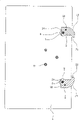
Fig. 1 is the front schematic view (blocking) of the embodiment of the invention;
Fig. 2 is the side schematic view (blocking) of the embodiment of the invention;
Fig. 3 is that the A-A of Fig. 2 is to sectional view;
Fig. 4 is the front schematic view (unlocking condition) of the embodiment of the invention;
Fig. 5 is the side schematic view (state that finishes of unblanking) of the embodiment of the invention;
Fig. 6 is the three-dimensional exploded view of the embodiment of the invention.
The specific embodiment
Embodiment describes in further detail the present invention below in conjunction with accompanying drawing.
Shown in Fig. 1~6, be a preferred embodiment of the present invention.
A kind of inverted hook type latch locking structure comprises door-plate 1, door bolt 2, and the door bolt in the present embodiment 2 has two, and door bolt 2 integral body are tabular, and the profile of the front end face 23 of door bolt 2 is curved.
Wherein, the rear portion of door bolt 2 is rotatably connected to door-plate 1 back side by screw 7, have a ladder through hole 24 on the rear positions of door bolt 2, one screw 7 passes these ladder hole 24 backs and is threaded with door-plate 1, the bar portion of this screw 7 has one section smooth department 71, and this smooth department 71 is positioned at the aperture portion of described ladder hole 24, is convenient to door bolt 2 around screw 7 axis tilts, the head 72 of screw then is positioned at the macropore portion of ladder hole 24, and described door bolt 2 is around screw 7 axis tilts.Also pad is provided with the hassock sheet 8 of a circle between door bolt 2 and door-plate 1, and shoulder hole 24 and hassock sheet 8 backs that screw 7 passes the door bolt head successively are threaded with door-plate 1.
Front end one side at door bolt 2 has outward extending hook portion 21, also have one at the rear portion of door bolt 2 vertical and away from the upwardly extending promotion post 22 in the side of door-plate 1, wherein, promote post 22 and can be to be weldingly fixed on the upper surface of door bolt 2, promote post 22 and can also be close-fitting and be plugged in the rear portion of door bolt 2, and the ladder hole 24 on the position that promotes post 22 and the door bolt 2 is contiguous.
Be provided with at door-plate 1 back side one with promote the driving mechanism that post 22 links to each other, this driving mechanism can promote post 22 so that fasten 2 relative door-plate 1 deflection with a bolt or latch, fastens 2 deflection with a bolt or latch and is at the plane intrinsic deflection parallel with door-plate 1.
Driving mechanism in the present embodiment includes and constrains in door-plate 1 back side and the slide plate 3 of door-plate 1 horizontal sliding relatively only, the structure that slide plate 3 constrains in door-plate 1 back side is, on front slide 3, have at least three length directions guiding slotted eye 31 consistent with slide plate 3 glide directions, correspondingly, door-plate 1 back side be provided with projection and and the corresponding respectively multidiameter 5 that matches of described guiding slotted eye 31, each multidiameter 5 is movable respectively to be passed corresponding guiding slotted eye 31 backs and carries out spacingly at the another sides of guiding slotted eye 31 with nut 6, and slide plate 3 lower surfaces that are close to door-plate 1 simultaneously are shelved on the cascaded surface of multidiameter 5.
Link to each other by driving member between the promotion post 22 on slide plate 3 and the described door bolt head, and so drive bolt 2 relative door-plate 1 deflection by the horizontal sliding of slide plate 3.
Driving member in the present embodiment is a driver plate 4, one end of this driver plate 4 and slide plate 3 fix by bolt nut structure, so driver plate 4 also can be with slide plate 3 relative door-plate 1 slippages, the lower position of driver plate 4 has the length direction bar shape trench hole 41 vertical with slide plate 3 glide directions, and described promotion post 22 passes this bar shape trench hole 41 also can be along the relative slippage of direction of bar shape trench hole 41 constraints.
As complete safety door structure, certainly also comprise and drive the structure that slide plate 3 moves, and the lock construction that stops slide plate 3 slippages, the structure that driving slide plate 3 moves can be to drive by the mode of locking plectrum, also drive with the mode that slide plate upper rack portion cooperates by toothed disc, it is routine techniques structure that driving slide plate 3 moves and the lock construction that stops slide plate 3 slippages, so do not draw in the accompanying drawings.
Door bolt head in the present embodiment has two, and accordingly, driver plate and screw also have two.
Concrete operating principle of the present invention is as follows:
As Fig. 1,2, shown in 3, during locking, drive slide plate 3 and on driver plate 4 level reach together, promotion post 22 on the door bolt 2 with driver plate 4 under the mating reaction of bar shape trench hole 41, driver plate 4 promotes door bolt 2 around screw 7 relative door-plates 1 angle of overturning, the bearing of trend of hook portion 21 is consistent on this reverses direction and the door bolt 2, be door bolt 2 a counterclockwise deflection of bottom, the 2 clockwise deflection of the door bolt on top, when slide plate 3 levels move forward under the ultimate limit state, the outer end of door bolt 2 has the trend of protracting, and simultaneously, the hook portion 21 on the door bolt 2 is in roughly vertically state, slide plate 3 is locked, can not after move, also make door bolt 2 remain at final state, the front end of door bolt 2 stretches in the latch hole, the hook portion 21 of door bolt head catches on the preceding inwall of latch hole simultaneously, prevent that effectively the lawless person from prizing the bolt 2 of buckle portion 21 from latch hole, latch hole is a conventional structure in the strongbox, does not show in drawing.
As Fig. 4, shown in 5, releasing process, contact is to the locking of slide plate 3, drive slide plate 3 and on driver plate 4 move after the level together, promotion post 22 on the door bolt 2 with driver plate 4 under the mating reaction of bar shape trench hole 41, driver plate 4 promotes door bolt 2 around angle of screw 7 relative door-plate 1 reverse flip, the bearing of trend of hook portion 21 is opposite on this reverses direction and the door bolt 2, i.e. the door bolt of bottom 2 a clockwise deflection, the 2 counterclockwise deflection of the door bolt on top, after slide plate 3 levels, move under the ultimate limit state, the trend that contracts in the outer end of door bolt 2 has, simultaneously, the hook portion 21 on the door bolt head is in the approximate horizontal state, the front end of door bolt 2 withdraws from latch hole, final release.
Claims (9)
1, a kind of inverted hook type latch locking structure, comprise door-plate (1), door bolt head (2), it is characterized in that: the rear portion of described door bolt head (2) is rotatably connected to door-plate (1) back side and has one vertical and away from the upwardly extending promotion post in the side of door-plate (1) (22), front end one side of described door bolt head (2) has outward extending hook portion (21), and be provided with at door-plate (1) back side one with promote the driving mechanism that post (22) links to each other, this driving mechanism can promote post (22) so that fasten (2) relative door-plate (1) deflection with a bolt or latch.
2, inverted hook type latch locking structure according to claim 1, it is characterized in that: described driving mechanism comprises and constrains in door-plate (1) back side and the slide plate (3) of door-plate (1) horizontal sliding relatively only, link to each other by driving member between the promotion post (22) on this slide plate (3) and the described door bolt head, and therefore relative door-plate (1) deflection of drive bolt head (2) by the horizontal sliding of slide plate (3).
3, inverted hook type latch locking structure according to claim 2, it is characterized in that: described driving member is a driver plate (4), one end of this driver plate (4) is fixed with slide plate (3) and can be with the relative door-plate of slide plate (3) (1) slippage, the lower position of driver plate (4) has the length direction bar shape trench hole (41) vertical with slide plate (3) glide direction, and described promotion post (22) passes this bar shape trench hole (41) also can be along the relative slippage of direction of bar shape trench hole (41) constraint.
4, inverted hook type latch locking structure according to claim 2, it is characterized in that: the structure that described slide plate (3) constrains in door-plate (1) back side is, on front slide (3), have at least two length directions guiding slotted eye (31) consistent with slide plate (3) glide direction, correspondingly, door-plate (1) back side be provided with projection and and the corresponding respectively multidiameter (5) that matches of described guiding slotted eye (31), each multidiameter (5) activity respectively passes corresponding guiding slotted eye (31) back and carries out spacingly at the another side of guiding slotted eye (31) with nut (6), and slide plate (3) lower surface that is close to door-plate simultaneously is shelved on the cascaded surface of multidiameter (5).
5, inverted hook type latch locking structure according to claim 2 is characterized in that: described door bolt head (2) has two, and these two door bolt heads (2) are positioned at the same side of door-plate (1), and these two door bolt heads (2) are positioned at the both sides of slide plate (3) simultaneously.
6, according to the described inverted hook type latch locking structure of arbitrary claim in the claim 1~5, it is characterized in that: described door bolt head (2) integral body is tabular, and the profile of the front end face (23) of door bolt head (2) is curved.
7, inverted hook type latch locking structure according to claim 6 is characterized in that: described door bolt head (2) is rotatably connected to door-plate (1) back side by screw (7).
8, inverted hook type latch locking structure according to claim 7, it is characterized in that: have a ladder through hole (24) on the described door bolt head (2), described screw (7) passes this ladder hole (24) back and is threaded with door-plate (1), the bar portion of this screw (7) has one section smooth department (71), this smooth department (71) is positioned at the aperture portion of described ladder hole (24), the head of screw (72) then is positioned at the macropore portion of ladder hole (24), and described door bolt head (2) is around screw (7) axis tilt.
9, inverted hook type latch locking structure according to claim 8, it is characterized in that: also fill up the hassock sheet (8) that is provided with a circle between described door bolt head (2) and the door-plate (1), shoulder hole (24) and hassock sheet (8) back that described screw (7) passes the door bolt head successively are threaded with door-plate (1).
Priority Applications (1)
| Application Number | Priority Date | Filing Date | Title |
|---|---|---|---|
| CN200910097753A CN101538984A (en) | 2009-04-17 | 2009-04-17 | Inverted hook type latch locking structure |
Applications Claiming Priority (1)
| Application Number | Priority Date | Filing Date | Title |
|---|---|---|---|
| CN200910097753A CN101538984A (en) | 2009-04-17 | 2009-04-17 | Inverted hook type latch locking structure |
Publications (1)
| Publication Number | Publication Date |
|---|---|
| CN101538984A true CN101538984A (en) | 2009-09-23 |
Family
ID=41122356
Family Applications (1)
| Application Number | Title | Priority Date | Filing Date |
|---|---|---|---|
| CN200910097753A Pending CN101538984A (en) | 2009-04-17 | 2009-04-17 | Inverted hook type latch locking structure |
Country Status (1)
| Country | Link |
|---|---|
| CN (1) | CN101538984A (en) |
Cited By (3)
| Publication number | Priority date | Publication date | Assignee | Title |
|---|---|---|---|---|
| CN102108819A (en) * | 2011-01-24 | 2011-06-29 | 王勇军 | Anti-pry bolt and bolt inserting structure having same |
| CN106996230A (en) * | 2017-06-13 | 2017-08-01 | 江苏金联金属制品有限公司 | A kind of keeper on oven |
| CN110284777A (en) * | 2019-06-12 | 2019-09-27 | 和信精密科技(吴江)有限公司 | A kind of simple quick release lock for cabinet door |
-
2009
- 2009-04-17 CN CN200910097753A patent/CN101538984A/en active Pending
Cited By (4)
| Publication number | Priority date | Publication date | Assignee | Title |
|---|---|---|---|---|
| CN102108819A (en) * | 2011-01-24 | 2011-06-29 | 王勇军 | Anti-pry bolt and bolt inserting structure having same |
| CN102108819B (en) * | 2011-01-24 | 2013-09-04 | 王勇军 | Bolt inserting structure of anti-pry bolt |
| CN106996230A (en) * | 2017-06-13 | 2017-08-01 | 江苏金联金属制品有限公司 | A kind of keeper on oven |
| CN110284777A (en) * | 2019-06-12 | 2019-09-27 | 和信精密科技(吴江)有限公司 | A kind of simple quick release lock for cabinet door |
Similar Documents
| Publication | Publication Date | Title |
|---|---|---|
| CN101705758B (en) | Free-swing handle structure for safe | |
| CN201087631Y (en) | Rotating latch structure for safe | |
| US11598124B2 (en) | Multipoint locking door hardware | |
| CN201406903Y (en) | Automatic door lock | |
| CN101566026A (en) | An automatic door lock | |
| CN203050294U (en) | Safe door locking mechanism used for safe | |
| CN102913075A (en) | Door locking mechanism used for safe box | |
| CN101538984A (en) | Inverted hook type latch locking structure | |
| CN100591882C (en) | Automatic locking antitheft lock | |
| CN101545330B (en) | Handle mechanism for violent-opening preventing safe box | |
| CN201539132U (en) | Free-swing handle structure for safe | |
| CN202039662U (en) | Anti-theft door bolt and bolt structure with same | |
| CN201391123Y (en) | Pry-proof bolt structure | |
| CN201106328Y (en) | Inverse hook type latch structure | |
| CN101059050A (en) | Pick-proof door bolt structure | |
| CN201416308Y (en) | Rotating bolt head and rotating bolt releasing mechanism with rotating bolt head | |
| CN101250961B (en) | Composite locking mechanism | |
| CN102094557B (en) | Anti-tamper bolt structure of safety box | |
| CN200940380Y (en) | Automatic locking lock | |
| CN201753543U (en) | Latch locking structure of safe | |
| CN102936983B (en) | Door lock for restroom | |
| CN201915752U (en) | Anti-prying latch structure | |
| CN102108819B (en) | Bolt inserting structure of anti-pry bolt | |
| CN101487368B (en) | Rotating latch head and latch beating mechanism with the same | |
| CN201176750Y (en) | Prying-proof door bolt structure |
Legal Events
| Date | Code | Title | Description |
|---|---|---|---|
| C06 | Publication | ||
| PB01 | Publication | ||
| C10 | Entry into substantive examination | ||
| SE01 | Entry into force of request for substantive examination | ||
| C02 | Deemed withdrawal of patent application after publication (patent law 2001) | ||
| WD01 | Invention patent application deemed withdrawn after publication |
Open date: 20090923 |