CN101513765A - Mold with cutting structure for injecting - Google Patents
Mold with cutting structure for injecting Download PDFInfo
- Publication number
- CN101513765A CN101513765A CNA2008100079569A CN200810007956A CN101513765A CN 101513765 A CN101513765 A CN 101513765A CN A2008100079569 A CNA2008100079569 A CN A2008100079569A CN 200810007956 A CN200810007956 A CN 200810007956A CN 101513765 A CN101513765 A CN 101513765A
- Authority
- CN
- China
- Prior art keywords
- module
- film
- cutting blade
- mould
- die cavity
- Prior art date
- Legal status (The legal status is an assumption and is not a legal conclusion. Google has not performed a legal analysis and makes no representation as to the accuracy of the status listed.)
- Pending
Links
Images


Abstract
The invention relates to a mould with a cutting structure for injecting. The mold is used for cutting a membrane in the mold, and is characterized by comprising a first module, a second module which can be opened or closed relative to the first module, and a cutting blade piece, wherein the cutting blade piece is arranged on the first module or the second module, while the membrane is arranged in the other module; and the first module and the second module are closed, and the membrane is supported against the cutting blade piece. Therefore, the cutting blade piece of the invention can perform accurate cutting treatment on the membrane in the mold in advance, and the mold not only can improve the finished product precision, but also can reduce the manpower, the time, and the equipment cost, and improve the production efficiency.
Description
Technical field
The present invention is relevant with mould, is meant a kind of ejaculation mould of tool cutting structure especially.
Background technology
For pursuing the high accuracy and the high-quality of plastic, traditional plastic processing technology can't satisfy the epoch demand, therefore various incrustation processing procedures in response to and give birth to, common processing procedure is for to insert a decorating film in the mould, and after the mould closure, carries out plastics and penetrate, make these plastics and this thin film connecting shaping, thus, the finished surface after the demoulding is coated with decorating film, thereby promotes the aesthetic property and the practicality of finished product.
But, because film need heat in mould and molding manufacture procedure, therefore, the film periphery is all reserved significantly burr, with the amount of contraction of absorbing membrane in the stereo shaping and the back generation of being heated, finished product 1 after the tradition demoulding as shown in Figure 1, its periphery 1a still leaves significantly film burr 2, must cut and the finishing program through follow-up burr 2 again, just can reach required aesthetic property of product and integrality, yet follow-up film burr 2 cutting operations must cut by artificial cutting or by blanking units, so will cause the puzzlement of processing once more, quite consuming time taking a lot of work in the operation, not only cause manpower, the increase of time and equipment cost, and production efficiency is not high, moreover, film burr 2 around the finished product 1 are after above-mentioned tradition cuts fabrication process, uneven situation still easily taking place, and then influence finished product 1 integral aesthetic property and exquisiteness, causes the economic worth of finished product 1 to reduce.In addition, commonly use the also even situation generation that flash is arranged in the ejection formation process, cause finished product 1 not attractive in appearance.
Summary of the invention
At the problems referred to above, main purpose of the present invention is to provide a kind of ejaculation mould of tool cutting structure, and it can produce the high accuracy finished product that the surface is coated with decorating film, and can reduce manpower, time and equipment cost, enhances productivity.
For achieving the above object, the ejaculation mould of a kind of tool cutting structure provided by the present invention is used to cut a film that is positioned at described mould, it is characterized in that comprising: one first module; One second module, it can described relatively first module be opened and closure; One cutting blade spare, on the module located therein, and another module is for described film setting wherein, closed described first, second module, described film and described cutting blade spare are inconsistent.
In the technical scheme of the invention described above, described first module has a die, described second module has the die cavity of the described die of a cooperation, described die and described die cavity enclose jointly and form a die cavity, the die cavity of described second module for described film setting wherein, and described film is corresponding to described die cavity, and described cutting blade spare is located at the die periphery of described first module.
In the technical scheme of the invention described above, when described first, second module was closed, described cutting blade spare was positioned at described die cavity, and is close to the internal face of the die cavity of described second module.
In the technical scheme of the invention described above, described cutting blade spare has a blade and protrudes into outside the die of described first module.
In the technical scheme of the invention described above, the die cavity periphery of described second module is provided with a cutter groove, and when described first, second module was closed, the blade of described cutting blade spare stretched into described cutter groove.
In the technical scheme of the invention described above, the blade length of described cutting blade spare is greater than the thickness of described film.
In the technical scheme of the invention described above, the blade length of described cutting blade spare equals the thickness of described film.
In the technical scheme of the invention described above, the blade length of described cutting blade spare is less than the thickness of described film.
In the technical scheme of the invention described above, the internal face of a side wall surface of the close described die cavity of described blade and the die cavity of described second module pastes neat.
In the technical scheme of the invention described above, the die periphery that described cutting blade spare is formed in one and is formed at described first module.
Adopt technique scheme, the present invention utilizes cutting blade spare at mould inside film to be carried out accurate cutting in advance and handles, can save the follow-up burr cutting operation after traditional finished product demoulding, thus, not only can improve finished product accuracy, also can reduce manpower, time and equipment cost, enhance productivity.
Description of drawings
Fig. 1 commonly uses the schematic diagram that the surface is coated with the demoulding finished product of film;
Fig. 2 is the side-looking structural representation of a preferred embodiment of the present invention;
Fig. 3 discloses first module of above-mentioned preferred embodiment and the solid combination schematic diagram of cutting blade spare;
Fig. 4 discloses the mould of above-mentioned preferred embodiment when matched moulds, and cutting blade spare is inconsistent with film;
Fig. 5 is the partial enlarged drawing of Fig. 4;
Fig. 6 to Fig. 8 is the action flow chart of mould when matched moulds and ejaculation of above-mentioned preferred embodiment, discloses cutting blade spare and cuts film;
Fig. 9 is the prepared demoulding finished product of mould that utilizes above-mentioned preferred embodiment;
Figure 10 is Fig. 8 roughly the same, discloses cutting blade spare and film is not cut off fully;
Figure 11 discloses the film morphology of the finished product that the another kind of demoulding makes.
The specific embodiment
Now lifting following examples also is elaborated to structure of the present invention, characteristics and effect in conjunction with the accompanying drawings.
At first, as Fig. 2, shown in Figure 3, ejaculation mould 100 for the tool cutting structure that a preferred embodiment of the present invention provided, mould 100 comprises one first module 10, one second module 20 and a cutting blade spare 30, mould 100 is to use in in-mould thin film connecting shaping manufacture process, make film F can be in advance in mould 100 inside cut processing through preposition, the structure of mould 100 that present embodiment now is described in detail in detail is as follows:
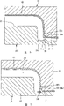
As Fig. 2~shown in Figure 5, first module 10 is in the present embodiment for being connected in an ejaculator (not shown), it has a die joint 11 and a tab-like die 12 that is formed in die joint 11, die 12 peripheries are around being provided with an annular slot 121, in addition, first module, 10 central authorities are provided with an injection channel 10a and are incident upon mould 100 inside for the plastics of ejaculator.
Cutting blade spare 30 is an annular framework at present embodiment, the one end is fastened in the annular slot 121 of die 12 peripheries of first module 10, the other end protrudes into outside the die 12, and form a blade 31, in the present embodiment, the length of blade 31 is greater than the thickness of film F, and its front end forms a beveled end 311, beveled end 311 near the height of a side of die cavities 101 less than height away from a side of die cavity 101.When first, second module 10,20 closures, cutting blade spare 30 is positioned at die cavity 101, and be close to the internal face 221 of the die cavity 22 of second module 20, its blade 31 stretches into the cutter groove 22a of die cavity 22, fully film F being cut off, and blade 31 pastes together near a side wall surface of die cavities 101 internal face 221 with the die cavity 22 of second module 20.
What must illustrate is that the draw-in groove 121 of first module 10 is not necessary assembly, can omit.In other words, cutting blade spare 30 can be used die 12 peripheries that integrated mode is formed at first module 10 instead.In addition, cutting blade spare 30 also can be movable, promptly, the operator can change the suitable cutting blade spare of length 30 according to the thickness of film F, or the fine setting by the guiding mechanism (not shown) makes cutting blade spare 30 produce displacements, to change the length of blade 31, can cooperate the film of different-thickness to use thus.And the shape of cutting blade spare 30 also not only is confined to above-mentioned annular framework.
More than be mould 100 each member of present embodiment and the explanation of relevant position thereof, then narrate it and apply to in-mould thin film connecting shaping manufacture process and effect that is produced and advantage:
As shown in Figure 2, when first, second module 10,20 is in opening, film F utilizes a clamping device 200 to insert in the mould 100 earlier, locate by clamping piece 23 clampings again, make the film F periphery all by the clamping packing, treat clamping piece 23 clamping film F after, clamping device 200 pine oil film F also withdraw to mould 100 outsides, then, film F is heated and is extended and be subjected to vacuum attraction and adhere well to die cavity 22 internal faces 221.Then, shown in the action flow chart of Fig. 4, Fig. 5 and Fig. 6 to Fig. 8, when first, second module 10,20 is operated closure, film F and cutting blade spare 30 are inconsistent and cut, must explanation be, in the present embodiment because blade 31 length of cutting blade spare 30 are greater than the thickness of film F, so film F can be completely severed, just burr can be taken advantage of a situation and are removed.Certainly, the operator also can adopt blade length to equal the cutting blade spare 30 of film F, so can reach identical purpose equally, and the cutter groove 22a of die cavity 22 also can save and do not establish.After having cut film F, plastics S enters along the injection channel 10a of first module 10, and with the film F connecting shaping in die cavity 101, last, carry out the die sinking operation, first, second module 10,20 is opened relatively, can obtain finished product 300 as shown in Figure 9, what should be specified is to be removed because the burr of film F are taken advantage of a situation in advance, so finished product 300 peripheries 301 do not have the film burr, therefore must can not obtain high accuracy and high surface structure attractive in appearance through secondary operations again.
Certainly, the length of the blade 31 of cutting blade spare 30 also can be less than the thickness of film F, promptly be as shown in figure 10, thus, the cutter groove 22a of second module 20 of the foregoing description also can save, in addition, blade 31 beveled ends 311 also can be near the height of a side of die cavity 101 greater than height away from a side of die cavity 101, so can reach the purpose that prevents flash equally.By said structure as can be known, after the mould closure, film F is not completely severed, so behind ejection formation, can obtain finished product 400 as shown in figure 11, because film F is in advance through appropriate cutting, therefore, the operator only needs the film F of finished product 400 peripheries 401 application of force a little, it can be taken off, can obtain high accuracy and high product attractive in appearance equally.
What deserves to be mentioned is that in addition the design of the blade 31 of tool beveled end 311 of the present invention is except that can reaching preferably cutting effect, more can be when plastics penetrate, plastics are blocked in mould 100 die cavities 101, avoid taking place flash situation of the prior art, to improve the exquisite degree and the aesthetics of finished product.Moreover, because internal face 221 subsides of the die cavity 22 of a side wall surface of blade 31 close die cavities 101 and second module 20 are neat, thus the precision that cuts is more improved, to improve the exquisite degree and the aesthetics of finished product.
In sum, the present invention directly utilizes the cutting blade spare 30 in the mould 100 that film F is carried out the preposition operation that cuts, make that film F burr ratio is easier to take off around the finished product 300 after the moulding, or utilize blade 31 than the long cutting blade spare of the thickness of the film F removal burr of directly taking advantage of a situation when mould 100 matched moulds, thus, than the person of commonly using, the design of cutting blade spare of the present invention can significantly reduce or save the secondary processing cost that the follow-up burr cutting operation of commonly using decorating film is caused, can save a large amount of manpowers, time and equipment cost, and the production efficiency height, and do not have commonly use the uneven situation that the film burr around the finished product are produced after pruning.Therefore, utilize the prepared finished product of mould of the present invention to have high exquisite degree and aesthetic property, have high commercial interest and surcharge.
The above only is a preferable possible embodiments of the present invention, and the equivalent structure that all application specification of the present invention, claims and accompanying drawing are done changes, and all should be included in the scope of patent protection of the present invention.
Claims (10)
1, a kind of ejaculation mould of tool cutting structure is used to cut a film that is positioned at described mould, it is characterized in that comprising:
One first module;
One second module, it can described relatively first module be opened and closure;
One cutting blade spare, on the module located therein, and another module is for described film setting wherein, closed described first, second module, described film and described cutting blade spare are inconsistent.
2, the ejaculation mould of tool cutting structure as claimed in claim 1, it is characterized in that: described first module has a die, described second module has the die cavity of the described die of a cooperation, described die and described die cavity enclose jointly and form a die cavity, the die cavity of described second module for described film setting wherein, and described film is corresponding to described die cavity, and described cutting blade spare is located at the die periphery of described first module.
3, the ejaculation mould of tool cutting structure as claimed in claim 2 is characterized in that: when described first, second module was closed, described cutting blade spare was positioned at described die cavity, and is close to the internal face of the die cavity of described second module.
4, the ejaculation mould of tool cutting structure as claimed in claim 2 is characterized in that: described cutting blade spare has a blade and protrudes into outside the die of described first module.
5, the ejaculation mould of tool cutting structure as claimed in claim 4 is characterized in that: the die cavity periphery of described second module is provided with a cutter groove, and when described first, second module was closed, the blade of described cutting blade spare stretched into described cutter groove.
6, the ejaculation mould of tool cutting structure as claimed in claim 4 is characterized in that: the blade length of described cutting blade spare is greater than the thickness of described film.
7, the ejaculation mould of tool cutting structure as claimed in claim 4, it is characterized in that: the blade length of described cutting blade spare equals the thickness of described film.
8, the ejaculation mould of tool cutting structure as claimed in claim 4 is characterized in that: the blade length of described cutting blade spare is less than the thickness of described film.
9, the ejaculation mould of tool cutting structure as claimed in claim 4 is characterized in that: the internal face of a side wall surface of the close described die cavity of described blade and the die cavity of described second module pastes neat.
10, the ejaculation mould of tool cutting structure as claimed in claim 2 is characterized in that: the die periphery that described cutting blade spare is formed in one and is formed at described first module.
Priority Applications (1)
| Application Number | Priority Date | Filing Date | Title |
|---|---|---|---|
| CNA2008100079569A CN101513765A (en) | 2008-02-21 | 2008-02-21 | Mold with cutting structure for injecting |
Applications Claiming Priority (1)
| Application Number | Priority Date | Filing Date | Title |
|---|---|---|---|
| CNA2008100079569A CN101513765A (en) | 2008-02-21 | 2008-02-21 | Mold with cutting structure for injecting |
Publications (1)
| Publication Number | Publication Date |
|---|---|
| CN101513765A true CN101513765A (en) | 2009-08-26 |
Family
ID=41038460
Family Applications (1)
| Application Number | Title | Priority Date | Filing Date |
|---|---|---|---|
| CNA2008100079569A Pending CN101513765A (en) | 2008-02-21 | 2008-02-21 | Mold with cutting structure for injecting |
Country Status (1)
| Country | Link |
|---|---|
| CN (1) | CN101513765A (en) |
Cited By (3)
| Publication number | Priority date | Publication date | Assignee | Title |
|---|---|---|---|---|
| CN102909824A (en) * | 2012-10-19 | 2013-02-06 | 珠海格力大金精密模具有限公司 | Device for producing components of filter screen |
| WO2019165639A1 (en) * | 2018-03-02 | 2019-09-06 | 彰洋材料股份有限公司 | Variable pressure injection mold, and injected shoe material and method for manufacturing same |
| CN111319167A (en) * | 2020-03-09 | 2020-06-23 | 张军堂 | Plastic product forming die |
-
2008
- 2008-02-21 CN CNA2008100079569A patent/CN101513765A/en active Pending
Cited By (4)
| Publication number | Priority date | Publication date | Assignee | Title |
|---|---|---|---|---|
| CN102909824A (en) * | 2012-10-19 | 2013-02-06 | 珠海格力大金精密模具有限公司 | Device for producing components of filter screen |
| CN102909824B (en) * | 2012-10-19 | 2015-03-11 | 珠海格力大金精密模具有限公司 | Device for producing components of filter screen |
| WO2019165639A1 (en) * | 2018-03-02 | 2019-09-06 | 彰洋材料股份有限公司 | Variable pressure injection mold, and injected shoe material and method for manufacturing same |
| CN111319167A (en) * | 2020-03-09 | 2020-06-23 | 张军堂 | Plastic product forming die |
Similar Documents
| Publication | Publication Date | Title |
|---|---|---|
| CN102642437B (en) | Carving and molding process of leather | |
| CN101804684A (en) | In-mould decorating injection moulding method and mould | |
| CN101513765A (en) | Mold with cutting structure for injecting | |
| CN104842503B (en) | A kind of manufacture method of advertisement and identifier board | |
| CN102529098B (en) | Method for manufacturing vehicle sign by in-mold decoration technology | |
| CN101513763A (en) | Processing procedures for cutting membrane in mold | |
| CN104972599A (en) | Injection molding technology of lampshade | |
| CN104227991A (en) | Short-period mold for thin-wall high-temperature material | |
| CN203650758U (en) | Large-size peroxide vulcanized EPDM sealing ring machining and molding device | |
| US9050746B2 (en) | IMD mold, injection molding apparatus having such an IMD mold and method for producing a film-decorated plastic part | |
| CN201437271U (en) | Multifunctional combined injection mold | |
| CN207156335U (en) | A kind of glass and the integrally formed mould structure of plastic cement | |
| CN211662565U (en) | Thin-wall part injection mold | |
| CN204019891U (en) | A kind of thin-walled high temperature material short period mould | |
| CN211221877U (en) | Automatic cut mouth of a river mould | |
| CN212948920U (en) | Mould with auxiliary insertion flow-resisting injection mould structure | |
| CN219705955U (en) | Spiral mould inscribing mouth of a river device | |
| KR20070044245A (en) | A catapult for inserting the film | |
| CN102350766B (en) | Die locking injection molding method for precutting soft small fabric | |
| CN218462687U (en) | Rapid forming shoe mold | |
| CN217993361U (en) | Novel mould is used in production of plastics gadget | |
| CN209738188U (en) | Cylinder type air conditioner rear shell forming die | |
| CN113954305B (en) | Forming die and forming process of automotive decorative ring | |
| CN208084809U (en) | A kind of sheet material shaving die and the adapted to injection system with sheet material shaving die | |
| CN210190423U (en) | Hot cutting injection mold in mold |
Legal Events
| Date | Code | Title | Description |
|---|---|---|---|
| C06 | Publication | ||
| PB01 | Publication | ||
| C10 | Entry into substantive examination | ||
| SE01 | Entry into force of request for substantive examination | ||
| C02 | Deemed withdrawal of patent application after publication (patent law 2001) | ||
| WD01 | Invention patent application deemed withdrawn after publication |
Open date: 20090826 |