CN1014255B - Fluid compressor - Google Patents
Fluid compressorInfo
- Publication number
- CN1014255B CN1014255B CN89104679A CN89104679A CN1014255B CN 1014255 B CN1014255 B CN 1014255B CN 89104679 A CN89104679 A CN 89104679A CN 89104679 A CN89104679 A CN 89104679A CN 1014255 B CN1014255 B CN 1014255B
- Authority
- CN
- China
- Prior art keywords
- cylinder
- mentioned
- bearing
- rotation
- solid
- Prior art date
- Legal status (The legal status is an assumption and is not a legal conclusion. Google has not performed a legal analysis and makes no representation as to the accuracy of the status listed.)
- Expired
Links
Images

Classifications
-
- F—MECHANICAL ENGINEERING; LIGHTING; HEATING; WEAPONS; BLASTING
- F04—POSITIVE - DISPLACEMENT MACHINES FOR LIQUIDS; PUMPS FOR LIQUIDS OR ELASTIC FLUIDS
- F04C—ROTARY-PISTON, OR OSCILLATING-PISTON, POSITIVE-DISPLACEMENT MACHINES FOR LIQUIDS; ROTARY-PISTON, OR OSCILLATING-PISTON, POSITIVE-DISPLACEMENT PUMPS
- F04C18/00—Rotary-piston pumps specially adapted for elastic fluids
- F04C18/08—Rotary-piston pumps specially adapted for elastic fluids of intermeshing-engagement type, i.e. with engagement of co-operating members similar to that of toothed gearing
- F04C18/12—Rotary-piston pumps specially adapted for elastic fluids of intermeshing-engagement type, i.e. with engagement of co-operating members similar to that of toothed gearing of other than internal-axis type
- F04C18/14—Rotary-piston pumps specially adapted for elastic fluids of intermeshing-engagement type, i.e. with engagement of co-operating members similar to that of toothed gearing of other than internal-axis type with toothed rotary pistons
- F04C18/16—Rotary-piston pumps specially adapted for elastic fluids of intermeshing-engagement type, i.e. with engagement of co-operating members similar to that of toothed gearing of other than internal-axis type with toothed rotary pistons with helical teeth, e.g. chevron-shaped, screw type
-
- F—MECHANICAL ENGINEERING; LIGHTING; HEATING; WEAPONS; BLASTING
- F04—POSITIVE - DISPLACEMENT MACHINES FOR LIQUIDS; PUMPS FOR LIQUIDS OR ELASTIC FLUIDS
- F04C—ROTARY-PISTON, OR OSCILLATING-PISTON, POSITIVE-DISPLACEMENT MACHINES FOR LIQUIDS; ROTARY-PISTON, OR OSCILLATING-PISTON, POSITIVE-DISPLACEMENT PUMPS
- F04C18/00—Rotary-piston pumps specially adapted for elastic fluids
- F04C18/08—Rotary-piston pumps specially adapted for elastic fluids of intermeshing-engagement type, i.e. with engagement of co-operating members similar to that of toothed gearing
- F04C18/10—Rotary-piston pumps specially adapted for elastic fluids of intermeshing-engagement type, i.e. with engagement of co-operating members similar to that of toothed gearing of internal-axis type with the outer member having more teeth or tooth equivalents, e.g. rollers, than the inner member
- F04C18/107—Rotary-piston pumps specially adapted for elastic fluids of intermeshing-engagement type, i.e. with engagement of co-operating members similar to that of toothed gearing of internal-axis type with the outer member having more teeth or tooth equivalents, e.g. rollers, than the inner member with helical teeth
Landscapes
- Engineering & Computer Science (AREA)
- Mechanical Engineering (AREA)
- General Engineering & Computer Science (AREA)
- Rotary Pumps (AREA)
- Applications Or Details Of Rotary Compressors (AREA)
Abstract
A fluid compressor includes cylinder, and a cylindrical rotating body located in the cylinder. One end of the cylinder is rotatably supported by a first bearing fixed to a case and the other end of the cylinder is slidably fitted with a second bearing. The second bearing is coupled with the first bearing through a support shaft which extends through the cylinder and rotatably supports the rotating body. A spiral groove is formed on the outer circumferential surface of the rotating body. A spiral blade is fitted into the groove and divides the space between the inner circumferential surface and the outer circumferential surface into a plurality of operating chambers which have volumes gradually decreasing with a distance from one end of the cylinder. When the cylinder and rotating body are relatively rotated, a fluid, introduced into the one end of the cylinder, is transferred toward the other end of the cylinder through the operating chambers and compressed during the transfer.
Description
The present invention relates to fluid compression engine, relate in particular to the fluid compression engine of refrigerant gas in for example compression refrigeration circulation.
Known have such as reciprocating type, rotary and similar various compressor.Yet the compression member of these compressors and drive part complex structure for example are delivered to bent axle on the compression member to turning power because of existing for, and just need to adopt many parts textural.In addition, in order to improve compression efficiency, safety check need be set and discharge side at it.Yet owing to there is bigger pressure difference on the both sides of this safety check, thereby gas is easy to miss through this valve, and compression efficiency can not be improved.In order to overcome these problems, need to improve the size and the installation precision of component out of the ordinary, this will cause manufacture cost to improve again.
American documentation literature U.S.P.No.2,401,189 disclose a kind of volute pump, and this prior art is the column-shape revolving-body that configuration one has a spiral slot on its outer surface in a sleeve, and a spiral vane is slidably mounted in this groove.When this solid of rotation rotation, the fluid that is limited by the two adjacent rings blade between solid of rotation outer surface and sleeve interior surface is transmitted to the other end by the end from sleeve.
Like this, this volute pump can only be used for conveyance fluid, and fluid is compressed.In fluid transmits, have only interior perimeter surface to contact when frequent maintenance of the outer surface of blade and sleeve, fluid-tight could be lived.Yet in solid of rotation revolution, owing to blade is not easy to make blade to slide smoothly to deformation sensitive, thereby to often keep that tight contact of perimeter surface is difficult in blade outer surface and the sleeve in spiral slot, thereby can not satisfactorily fluid-tight be lived.Therefore, the volute pump of this structure can not produce compression effectiveness.
The present invention carries out in view of above problem, and so that simple structure to be provided, compression efficiency is good, and also making parts manufacturing and assembling be easy to fluid compression engine is purpose.
For achieving the above object, fluid compression engine of the present invention comprises airtight housing; Be arranged in the above-mentioned housing, have the cylinder of suction side and exhaust end; Be fixedly installed in the above-mentioned housing, the clutch shaft bearing that an end of said cylinder can be supported freely to rotate, this clutch shaft bearing is used to an above-mentioned end of cylinder is clogged airtightly; Can be free to slide engage with the other end of said cylinder, and be used for second bearing that this end of cylinder is filled in airtightly; The supporting axle that above-mentioned first and second bearings couple together, this supporting axle is extended in said cylinder along the cylinder axis direction in, relatively cylinder axis becomes eccentric configuration; When being arranged in the said cylinder along the axle direction of cylinder, interior perimeter surface in one portion and said cylinder is contacted under the state might be pivotally and by the cylindric solid of rotation of above-mentioned support shaft supports, this solid of rotation has on its outer surface and forms, the groove that extends of shape in the shape of a spiral, the pitch that makes this groove reduces to discharging side gradually from the suction side of said cylinder; When can be entrenched in the above-mentioned groove, have the outer surface of being close to perimeter surface in the said cylinder with being free to slide, the spatial division between the outer surface of the interior perimeter surface of said cylinder and solid of rotation is become the spiral blade of a plurality of working rooms along the depth direction of groove; Make said cylinder and solid of rotation do relative revolution, flow into the driving mechanism that the interior fluid of above-mentioned operating chamber transmits to the operating chamber of cylinder discharge side successively from the above-mentioned suction side of cylinder thereby make.
According to the fluid compression engine of above-mentioned formation, then by making fluid transmit and can carry out high efficiency compression from the suction side of cylinder to discharging side.In addition, in first and second bearings, bearing fixing on one side is arranged in the housing, the bearing of another side is connected with bearing on one side by supporting axle.Thereby can make these bearings easily with correctly concentric mutually.In addition, owing to first and second bearings are interconnected, thereby can support cylinder and make and have and dual-supporting structure bearing equal stability generally by supporting axle.
To brief description of drawings.
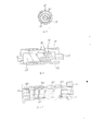
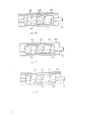
Fig. 1 to Fig. 8 is the fluid compression engine of the relevant one embodiment of the invention of expression, Fig. 1 is the above-mentioned compressor sectional drawing, Fig. 2 is an exploded representation above-mentioned compressor fragmentary cross-sectional view, Fig. 3 is the shaft side figure of solid of rotation, Fig. 4 is the shaft side figure of blade, Fig. 5 is along Fig. 1 V-V line sectional drawing, Fig. 6 is the figure of expression solid of rotation and suction tank configuration relation, Fig. 7 A to Fig. 7 D is for representing the sectional drawing of refrigerant gas compression processes respectively, Fig. 8 A to Fig. 8 D is illustrated respectively in the cylinder in the above-mentioned compression process and the sectional drawing of solid of rotation relative position, and Fig. 9 is the plan view of expression suction tank variation.
Followingly the embodiment of the invention is elaborated with reference to accompanying drawing.
Fig. 1 is the embodiment that expression is used for the present invention the refrigerant gas of refrigeration cycle is carried out compressor for compressing.
This compressor possesses enclosing housing 10 and is configured in this housing interior motor portion 12 and compression member 14.Motor portion 12 comprises the stator that is roughly ring-type 16 on the inner face that is fixedly mounted on housing 10 and is arranged on the ring-type rotor 18 of stator inboard.
As depicted in figs. 1 and 2, compression member 14 has cylinder 20, motor rotor 18 is fixed on coaxially on the outer circumferential face of this cylinder.Make the right-hand member of cylinder 20 with being fixedly installed on clutch shaft bearing 21 on housing 10 internal surfaces, just the suction side can be supported freely to rotate.In view of the above, make cylinder 20 be subjected to cantilever support, and make cylinder and rotor 18 be arranged to coaxial with stator 16 with bearing 21.Particularly the suction side with cylinder 20 is entrenched in the 21a of circumferential surface portion of bearing 21, and enables freely to turn round, and with this bearing it is lived airtightly by obturation.
In addition, the left end that second bearing 22 is installed in cylinder 20 is just discharged on the side.Particularly, be entrenched on the perimeter surface part 22a of bearing 22, and it can freely be turned round, and this end is clogged airtightly with this bearing the exhaust end of cylinder 20.And be second bearing 22 to be connected with clutch shaft bearing 21 by extending in the supporting axle 24 that extends in the cylinder 20.Be configured to supporting axle 24 make the central axis B of its central axis A and cylinder 20 to be parallel to each other, and only have eccentric distance e.One end of supporting axle 24 is pressed in the blind hole 21b that forms on the clutch shaft bearing 21, makes its other end run through the through hole 22b that forms by on second bearing 22, and stretch out foreign side at bearing 22.On the external part of supporting axle 24, be formed with radial direction through hole 24a, and, in through hole 24a, insert fixing pin 26, and an end of fixing pin is fixed on the bearing 22.Therefore, the 2nd bearing 22 is fixed on the other end of supporting axle 24 with fixing pin 26 and makes its revolution relatively mutually.
Like this, with second bearing 22 exhaust end of cylinder 20 can be supported freely to rotate.
In addition, such as depicted in figs. 1 and 2, on the right-hand member outer surface of solid of rotation 28, form engagement groove 30, make the drive pin 32 that stretches out from the interior perimeter surface of cylinder 20, along path cylinder to inserting in this engagement groove with freeing in and out.Therefore, when to motor portion 12 energisings, when cylinder 20 and rotor 18 are turned round together, make the turning power of cylinder be passed to solid of rotation 28 by pin 32.Its result turns round solid of rotation 28 in cylinder under the internal surface of its surperficial part and cylinder 20 contacts state.
As shown in Figure 1 to Figure 3, on the outer surface of solid of rotation 28, form, and the spiral slot 34 that between the solid of rotation two ends, extends.And, as can be seen from Figure 3, form the spacing make groove 34 from the right-hand member of cylinder 20 to left end, just the suction side from cylinder slowly diminishes to discharging side.Also chimeric spiral blade 36 as shown in Figure 4 in this groove 34.Herein, what make the thickness t of blade 36 and groove 34 roomyly causes equally, makes the each several part of blade become the radially opposed slot 34 of being on good terms along solid of rotation 28 and frees in and out.In addition, the outer surface of blade 36 is being slided under the situation of the interior perimeter surface of being close to cylinder 20 on the interior perimeter surface at cylinder.This blade 36 is to make with the elastic material of polytetrafluoroethylene (trade mark) etc., goes in groove 34 grooves by utilizing its elasticity spinning.
And, with blade 36 separated by spaces between the outer surface of the interior perimeter surface of cylinder 20 and solid of rotation 28 is become a plurality of working rooms 38.Each working room 38 is by the space defined of 36 in two adjacent rings blade, and that shows and forms from the contacting part of the interior perimeter surface of solid of rotation 28 and cylinder 20 to next time contacting part and roughly become crescent-shaped along what blade extended like that as shown in Figure 5.And, the volume that makes working room 38 along with from the suction side of cylinder 20 towards discharging skidding and then slowly diminishing.
As depicted in figs. 1 and 2, on clutch shaft bearing 21, run through the inlet hole 40 of formation along the axle direction extension of cylinder 20.An end that makes this inlet hole 40 is connected the suction pipe 42 of its other end and refrigeration cycle to the suction side of cylinder 20 inner opening.On second bearing 22, form the exhaust port 44 that extends along the axle direction of cylinder 20.Make the discharge side opening of an end of this tap hole 44, make its other end towards housing 10 inside openings to cylinder 20.In addition, accumulate lubricant oil 46 in the bottom of housing 10.
In addition, as shown in Figure 6, on the outer surface of the suction end of solid of rotation 28, form the guide groove 48 that refrigerant gas will be sucked.Form and make this guide groove 48 staggered, and extend to till the working room 38 that is positioned at position, the most close suction side from the suction end of solid of rotation 28 and spiral groove 34.And forming makes guide groove 48 darker than the degree of depth of groove 34.Therefore, make the refrigerant gas that flows in the cylinder 20 by inlet hole 40,, import the working room 38 that is positioned at position, the most close suction side by guide groove 48.In addition, as shown in Figure 9, the tip portion 48a that also can make guide groove 48 is along groove 34 bendings.
In Fig. 1, the 50th, the discharge tube of expression and housing 10 internal communication.
Below, the compressor action of above formation is described.
At first, make motor portion 12 energising, then rotor 18 and cylinder 20 revolutions that become one with it.Simultaneously, making solid of rotation 28 obtain revolution under the interior perimeter surface of the part of its outer surface and cylinder 20 contacts state drives.The relative rotation motion of such solid of rotation 28 like this and cylinder 20 shown in Fig. 8 A to Fig. 8 D, the limting mechanism that is made of pin 32 and engagement groove 30 guarantees.And, blade 36 is also turned round with solid of rotation 28 one.
Because blade 36 is that the perimeter surface state of contacting turns round in its outer surface and cylinder 20, therefore the each several part of blade 36 is pushed in the groove 34 along with being pressed towards near the contacting part of the interior perimeter surface of the outer surface of solid of rotation 28 and cylinder 20, and moves towards the direction that flies out from groove 34 along with leaving this contacting part.Make compression member 14 actions on the other hand, refrigerant gas is inhaled in the cylinder 20 by suction pipe 42 and inlet hole 40.This gas at first is closed in the working room 38 that is positioned at the suction side.And, such shown in Fig. 7 a to Fig. 7 D, follow the revolution of solid of rotation 28, above-mentioned gas under the state between the two adjacent rings that is closed in blade 36 is shifted to the working room 38 that discharges side successively, since the volume of working room 38 along with from the suction side of cylinder 20 to discharging skidding and then slowly diminishing, refrigerant gas slowly is being compressed during sidesway send to discharging.And, the refrigerant gas that has been subjected to compression is discharged in housing 10 from the tap hole 44 that forms at bearing 22, and then makes to turn back in the refrigeration cycle by pipe 50 and go.
According to the compressor of above formation, the pitch that need make on solid of rotation 28 spiral chute 34 that forms slowly diminishes to discharging side from the suction side of cylinder 20.The volume of the working room 38 of separating according to blade is slowly diminished towards discharging side, refrigerant gas is compressed during sidesway send to discharging in the suction side from cylinder 20.In addition, be transferred and be compressed, therefore,, also can compress gas expeditiously even expulsion valve is not set in the discharge side of compressor owing to make under the state of refrigerant gas in being closed in working room 38.
Owing to can save expulsion valve, can reach the purpose that makes compressor constructions oversimplify and reduce the spare part number.In addition, owing to be the rotor 18 that comes supporting motor part 12 with the cylinder 20 of compression member 14, so do not need to be provided with and be used for the turning axle of supporting rotor and bearing etc. specially.Therefore can further make the compressor arrangement simplification and make the spare part decreased number.
Because along being in contact with one another under the same direction turn state, therefore, the frictional force between these parts is little mutually for cylinder 20 and supporting axle 24, can distinguish revolution successfully, its result's vibration and noise are also little.
In addition, second bearing 22 is installed in clutch shaft bearing and carries out on the free end of cylinder 20 of cantilever support, and is used for supporting this free end, it is not fixed on the housing 10, and is connected with clutch shaft bearing by supporting axle 24.Therefore and the occasion that is fixed on housing 10 internal surfaces of second bearing compare, make second bearing can with clutch shaft bearing easily and correctly concentric, and can prevent that cylinder 20 relative bearings 21,22 are stuck, and can guarantee that cylinder turns round smoothly.
In addition, owing to make second bearing 22 and clutch shaft bearing 21 form mechanical connection, therefore can make the free end of cylinder 20 be subjected to stable support by supporting axle 24.Therefore, though be the structure that only clutch shaft bearing 21 is fixedly mounted on the housing 10, become might with first, second, both roughly equal stability of so-called dual-supportings structure of all being fixedly installed in the housing 10 of bearing 21,22 support cylinder 20.Its result can make the reliability of compressor improve.
In addition, owing to there is no need to make on the second bearing 22 fixed installation housings 10, thereby improved the degrees of freedom of case design, made and freely design hull shape and size becomes possibility.The transmission capacity of compressor is the initial pitch by blade 36, and the capacity of working room 38 that just is positioned at the suction side of cylinder 20 decides.If according to present embodiment, slowly diminish to discharging side from the suction side of cylinder 20 owing to be the spacing that makes blade.Therefore present embodiment with have the same number of turns, and be etc. that the occasion of pitch blade is compared, if the employing present embodiment along the solid of rotation total length, the desirable higher value of initial pitch of blade then, its result can make the quantity delivered of compressor big, in other words, can make high efficiency compressor.
In addition, if according to present embodiment, make the refrigerant gas of the suction side that flows into cylinder 20 introduce the working room 38 of initial positions by the guide groove 48 that on solid of rotation 28 ends, forms.For this reason, can therefore can improve the compression efficiency of compressor to the working room of the initial position 38 correct refrigeration dielectric gass of supplying with.
In addition, if reduce the design quantity delivered of fluid, when the number of turns increase more of blade 36, the pressure difference of then adjacent two operating chamber reduces more, and the mutual gas leakage amount of operating chamber is lowered, and its result improves compression efficiency.
The invention is not restricted to the foregoing description, can do various distortion within the scope of the present invention.
For example, fluid compression engine of the present invention is not limited to refrigeration cycle, also can be used for other machine.In addition, the method for second bearing fixing on supporting axle is not limited to lock pin, also the end of supporting axle can be pressed in the through hole 22b of bearing, and, the relative revolution of supporting axle and bearing prevented with key.In addition, also can be by respectively the through hole 22b of the end of supporting axle and second bearing 22 being taken as the relative revolution that polygon prevents supporting axle and bearing.
Claims (8)
1, fluid compression engine, comprise closed shell 10, be arranged in the above-mentioned housing 10, cylinder 20 with suction side and exhaust end, be used for connecting the clutch shaft bearing 21 and second bearing 22, along axially in cylinder 20, extending of cylinder 20, and the supporting axle 24 that the eccentric shaft of phase countercylinder 20 is provided with, the interior perimeter surface that is bearing in the part that makes its outer circumferential face and said cylinder 20 with this supporting axle 24 contacts and turns round under the state, have on its outer surface from the suction side of cylinder 20 and discharge the cylindrical solid of rotation 28 of the spiral chute 30 of side extension to it, depth direction along above-mentioned groove 30 can be entrenched in the above-mentioned groove 30 with being free to slide, has the outer surface that contacts closely with the interior perimeter surface of said cylinder 20, the spiral vane 36 that space between the outer surface of the interior perimeter surface of said cylinder 20 and solid of rotation 28 is divided into a plurality of working rooms, make said cylinder 20 carry out relative the revolution with solid of rotation 28, the driving mechanism that the fluid that flows into above-mentioned working room from the suction side of said cylinder 20 is transmitted to the discharge side of cylinder 20 successively, it is characterized in that making the pitch of above-mentioned groove 30 to discharge side from the suction side of cylinder 20 to it diminishes gradually, above-mentioned clutch shaft bearing 21 is fixed in the said cylinder 10, in the time of airtight the sealing of an end of said cylinder 20, this end of cylinder 20 can freely be turned round, in addition,, this end of cylinder 20 and the 2nd bearing 22 are formed be slidingly connected the other end of cylinder 20 is airtight when sealing with above-mentioned second bearing 22.
2, fluid compression engine according to claim 1, it is characterized in that above-mentioned supporting axle 24 has an end that is fixedly mounted on the above-mentioned clutch shaft bearing and the other end that is installed on above-mentioned second bearing respectively, above-mentioned solid of rotation has the endoporus 30a that forms with the central axis coaxial line of supporting axle 24, above-mentioned supporting axle 24 can be inserted freely to rotate lead in this hole.
3, fluid compression engine according to claim 2, it is characterized in that above-mentioned clutch shaft bearing has the outer surface in the end that can be installed in said cylinder freely to rotate, with along the axially extended hole 21b of cylinder, an end of above-mentioned supporting axle 24 is pressed in the above-mentioned hole.
4, fluid compression engine according to claim 3, it is characterized in that above-mentioned second bearing has the outer surface in the other end that said cylinder can be installed freely to rotate, with with above-mentioned clutch shaft bearing 21 on the through hole 22b of hole coaxial line, when the other end of above-mentioned supporting axle 24 being run through insert above-mentioned hole, protruding from second bearing 22, and then second bearing is had the other end of above-mentioned supporting axle 24 is fixedly mounted on second bearing 22, and make it can not rotating fixed component 26.
5, fluid compression engine according to claim 4 is characterized in that external part upper edge supporting axle warp-wise that the said fixing parts are included in above-mentioned supporting axle 24 runs through the joining hole 24a of formation and is inserted in the above-mentioned joining hole and is fixed in shotpin 26 on above-mentioned second bearing 22.
6, fluid compression engine according to claim 1, it is characterized in that, the clutch shaft bearing 21 of the suction end of supporting said cylinder 20 has inlet hole 40, the second bearings 22 that the fluid that is inhaled into from housing 10 foreign sides is imported in the cylinder and have a tap hole 44 that compressed above-mentioned fluid is discharged in said cylinder 20 in above-mentioned housing 10.
7, fluid compression engine according to claim 1, it is characterized in that above-mentioned driving mechanism comprises makes said cylinder 20 rotating motor portion 12 and said cylinder 20 rotating power are transmitted to above-mentioned solid of rotation 28, makes solid of rotation 28 and cylinder 20 carry out synchronous rotating driving mechanism.
8, fluid compression engine according to claim 7, it is characterized in that above-mentioned driving mechanism is included in the engagement groove 30 that forms on the outer surface of above-mentioned solid of rotation 28, when stretching out, can move radially and insert along cylinder 20 and stretch out body 32 in the above-mentioned engagement groove from the interior perimeter surface of said cylinder 20.
Applications Claiming Priority (2)
| Application Number | Priority Date | Filing Date | Title |
|---|---|---|---|
| JP170696/88 | 1988-07-08 | ||
| JP63170696A JPH0219686A (en) | 1988-07-08 | 1988-07-08 | Fluid compressor |
Publications (2)
| Publication Number | Publication Date |
|---|---|
| CN1039469A CN1039469A (en) | 1990-02-07 |
| CN1014255B true CN1014255B (en) | 1991-10-09 |
Family
ID=15909704
Family Applications (1)
| Application Number | Title | Priority Date | Filing Date |
|---|---|---|---|
| CN89104679A Expired CN1014255B (en) | 1988-07-08 | 1989-07-06 | Fluid compressor |
Country Status (5)
| Country | Link |
|---|---|
| US (1) | US4948347A (en) |
| JP (1) | JPH0219686A (en) |
| KR (1) | KR910009222B1 (en) |
| CN (1) | CN1014255B (en) |
| DE (1) | DE3922434A1 (en) |
Families Citing this family (2)
| Publication number | Priority date | Publication date | Assignee | Title |
|---|---|---|---|---|
| FR2877700B1 (en) * | 2004-11-09 | 2007-08-31 | Christian Bratu | MIXED PUMP |
| JP4844489B2 (en) * | 2007-07-19 | 2011-12-28 | 株式会社豊田自動織機 | Fluid machinery |
Family Cites Families (5)
| Publication number | Priority date | Publication date | Assignee | Title |
|---|---|---|---|---|
| US2397139A (en) * | 1941-06-05 | 1946-03-26 | Herman C Heaton | Rotary helical fluid unit |
| US2401189A (en) * | 1944-05-12 | 1946-05-28 | Francisco A Quiroz | Rotary pump construction |
| US3240155A (en) * | 1965-01-21 | 1966-03-15 | Quiroz Francisco Angel | Helical rotary pumps |
| EP0301273B1 (en) * | 1987-07-31 | 1993-02-03 | Kabushiki Kaisha Toshiba | Fluid compressor |
| DE3830746A1 (en) * | 1987-09-10 | 1989-03-23 | Toshiba Kawasaki Kk | FLUID COMPRESSORS |
-
1988
- 1988-07-08 JP JP63170696A patent/JPH0219686A/en active Pending
-
1989
- 1989-07-06 CN CN89104679A patent/CN1014255B/en not_active Expired
- 1989-07-07 US US07/376,515 patent/US4948347A/en not_active Expired - Fee Related
- 1989-07-07 DE DE3922434A patent/DE3922434A1/en active Granted
- 1989-07-07 KR KR1019890009663A patent/KR910009222B1/en not_active IP Right Cessation
Also Published As
| Publication number | Publication date |
|---|---|
| US4948347A (en) | 1990-08-14 |
| KR900001981A (en) | 1990-02-27 |
| DE3922434A1 (en) | 1990-01-11 |
| DE3922434C2 (en) | 1991-08-29 |
| CN1039469A (en) | 1990-02-07 |
| JPH0219686A (en) | 1990-01-23 |
| KR910009222B1 (en) | 1991-11-05 |
Similar Documents
| Publication | Publication Date | Title |
|---|---|---|
| US4547137A (en) | Scroll type fluid compressor with thickened spiral elements | |
| EP0301273B1 (en) | Fluid compressor | |
| EP2251545A1 (en) | A rotary compressor | |
| US7201568B2 (en) | Scroll fluid machine | |
| US20040184943A1 (en) | Fluid machinery | |
| US4872820A (en) | Axial flow fluid compressor with angled blade | |
| EP0683321B1 (en) | Swinging rotary compressor | |
| US7238011B2 (en) | Scroll compressor | |
| CN1014255B (en) | Fluid compressor | |
| EP0376049B1 (en) | Fluid compressor | |
| KR100486603B1 (en) | Capacity changeable apparatus for scroll compressor | |
| CN1048437A (en) | Fluid compression engine | |
| EP0381061B1 (en) | Fluid compressor | |
| CN1034752C (en) | Fluid pump and rotary machine having said fluid pump | |
| US5326239A (en) | Fluid compressor having a horizontal rotation axis | |
| CN1014256B (en) | Fluid compressor | |
| KR100343727B1 (en) | Structure for supporting crankshaft of scroll compressor | |
| JPH0219684A (en) | Fluid compressor | |
| JPH0219683A (en) | Fluid compressor | |
| JPH0219682A (en) | Fluid compressor | |
| US5368456A (en) | Fluid compressor with bearing means disposed inside a rotary rod | |
| JPH02201082A (en) | Fluid compressor | |
| JPH07107391B2 (en) | Fluid compressor | |
| JPH0267490A (en) | Fluid compressor | |
| JP2880771B2 (en) | Fluid compressor |
Legal Events
| Date | Code | Title | Description |
|---|---|---|---|
| C10 | Entry into substantive examination | ||
| SE01 | Entry into force of request for substantive examination | ||
| C06 | Publication | ||
| PB01 | Publication | ||
| C13 | Decision | ||
| GR02 | Examined patent application | ||
| C14 | Grant of patent or utility model | ||
| GR01 | Patent grant | ||
| C19 | Lapse of patent right due to non-payment of the annual fee | ||
| CF01 | Termination of patent right due to non-payment of annual fee |