CN101410739A - Process for making an optical film - Google Patents
Process for making an optical film Download PDFInfo
- Publication number
- CN101410739A CN101410739A CNA2007800115516A CN200780011551A CN101410739A CN 101410739 A CN101410739 A CN 101410739A CN A2007800115516 A CNA2007800115516 A CN A2007800115516A CN 200780011551 A CN200780011551 A CN 200780011551A CN 101410739 A CN101410739 A CN 101410739A
- Authority
- CN
- China
- Prior art keywords
- film
- draw
- polymeric material
- processing conditions
- optical thin
- Prior art date
- Legal status (The legal status is an assumption and is not a legal conclusion. Google has not performed a legal analysis and makes no representation as to the accuracy of the status listed.)
- Pending
Links
Images


Classifications
-
- G—PHYSICS
- G02—OPTICS
- G02F—OPTICAL DEVICES OR ARRANGEMENTS FOR THE CONTROL OF LIGHT BY MODIFICATION OF THE OPTICAL PROPERTIES OF THE MEDIA OF THE ELEMENTS INVOLVED THEREIN; NON-LINEAR OPTICS; FREQUENCY-CHANGING OF LIGHT; OPTICAL LOGIC ELEMENTS; OPTICAL ANALOGUE/DIGITAL CONVERTERS
- G02F1/00—Devices or arrangements for the control of the intensity, colour, phase, polarisation or direction of light arriving from an independent light source, e.g. switching, gating or modulating; Non-linear optics
- G02F1/01—Devices or arrangements for the control of the intensity, colour, phase, polarisation or direction of light arriving from an independent light source, e.g. switching, gating or modulating; Non-linear optics for the control of the intensity, phase, polarisation or colour
- G02F1/13—Devices or arrangements for the control of the intensity, colour, phase, polarisation or direction of light arriving from an independent light source, e.g. switching, gating or modulating; Non-linear optics for the control of the intensity, phase, polarisation or colour based on liquid crystals, e.g. single liquid crystal display cells
- G02F1/133—Constructional arrangements; Operation of liquid crystal cells; Circuit arrangements
- G02F1/1333—Constructional arrangements; Manufacturing methods
- G02F1/1335—Structural association of cells with optical devices, e.g. polarisers or reflectors
- G02F1/13363—Birefringent elements, e.g. for optical compensation
-
- G—PHYSICS
- G02—OPTICS
- G02B—OPTICAL ELEMENTS, SYSTEMS OR APPARATUS
- G02B5/00—Optical elements other than lenses
- G02B5/30—Polarising elements
- G02B5/3008—Polarising elements comprising dielectric particles, e.g. birefringent crystals embedded in a matrix
-
- B—PERFORMING OPERATIONS; TRANSPORTING
- B29—WORKING OF PLASTICS; WORKING OF SUBSTANCES IN A PLASTIC STATE IN GENERAL
- B29C—SHAPING OR JOINING OF PLASTICS; SHAPING OF MATERIAL IN A PLASTIC STATE, NOT OTHERWISE PROVIDED FOR; AFTER-TREATMENT OF THE SHAPED PRODUCTS, e.g. REPAIRING
- B29C55/00—Shaping by stretching, e.g. drawing through a die; Apparatus therefor
- B29C55/02—Shaping by stretching, e.g. drawing through a die; Apparatus therefor of plates or sheets
- B29C55/023—Shaping by stretching, e.g. drawing through a die; Apparatus therefor of plates or sheets using multilayered plates or sheets
-
- B—PERFORMING OPERATIONS; TRANSPORTING
- B29—WORKING OF PLASTICS; WORKING OF SUBSTANCES IN A PLASTIC STATE IN GENERAL
- B29C—SHAPING OR JOINING OF PLASTICS; SHAPING OF MATERIAL IN A PLASTIC STATE, NOT OTHERWISE PROVIDED FOR; AFTER-TREATMENT OF THE SHAPED PRODUCTS, e.g. REPAIRING
- B29C55/00—Shaping by stretching, e.g. drawing through a die; Apparatus therefor
- B29C55/02—Shaping by stretching, e.g. drawing through a die; Apparatus therefor of plates or sheets
- B29C55/10—Shaping by stretching, e.g. drawing through a die; Apparatus therefor of plates or sheets multiaxial
- B29C55/12—Shaping by stretching, e.g. drawing through a die; Apparatus therefor of plates or sheets multiaxial biaxial
- B29C55/14—Shaping by stretching, e.g. drawing through a die; Apparatus therefor of plates or sheets multiaxial biaxial successively
- B29C55/146—Shaping by stretching, e.g. drawing through a die; Apparatus therefor of plates or sheets multiaxial biaxial successively firstly transversely to the direction of feed and then parallel thereto
-
- B—PERFORMING OPERATIONS; TRANSPORTING
- B29—WORKING OF PLASTICS; WORKING OF SUBSTANCES IN A PLASTIC STATE IN GENERAL
- B29C—SHAPING OR JOINING OF PLASTICS; SHAPING OF MATERIAL IN A PLASTIC STATE, NOT OTHERWISE PROVIDED FOR; AFTER-TREATMENT OF THE SHAPED PRODUCTS, e.g. REPAIRING
- B29C55/00—Shaping by stretching, e.g. drawing through a die; Apparatus therefor
- B29C55/02—Shaping by stretching, e.g. drawing through a die; Apparatus therefor of plates or sheets
- B29C55/10—Shaping by stretching, e.g. drawing through a die; Apparatus therefor of plates or sheets multiaxial
- B29C55/12—Shaping by stretching, e.g. drawing through a die; Apparatus therefor of plates or sheets multiaxial biaxial
- B29C55/16—Shaping by stretching, e.g. drawing through a die; Apparatus therefor of plates or sheets multiaxial biaxial simultaneously
- B29C55/165—Apparatus therefor
-
- G—PHYSICS
- G02—OPTICS
- G02B—OPTICAL ELEMENTS, SYSTEMS OR APPARATUS
- G02B5/00—Optical elements other than lenses
- G02B5/30—Polarising elements
-
- G—PHYSICS
- G02—OPTICS
- G02B—OPTICAL ELEMENTS, SYSTEMS OR APPARATUS
- G02B5/00—Optical elements other than lenses
- G02B5/30—Polarising elements
- G02B5/3083—Birefringent or phase retarding elements
-
- B—PERFORMING OPERATIONS; TRANSPORTING
- B29—WORKING OF PLASTICS; WORKING OF SUBSTANCES IN A PLASTIC STATE IN GENERAL
- B29K—INDEXING SCHEME ASSOCIATED WITH SUBCLASSES B29B, B29C OR B29D, RELATING TO MOULDING MATERIALS OR TO MATERIALS FOR MOULDS, REINFORCEMENTS, FILLERS OR PREFORMED PARTS, e.g. INSERTS
- B29K2067/00—Use of polyesters or derivatives thereof, as moulding material
-
- B—PERFORMING OPERATIONS; TRANSPORTING
- B29—WORKING OF PLASTICS; WORKING OF SUBSTANCES IN A PLASTIC STATE IN GENERAL
- B29K—INDEXING SCHEME ASSOCIATED WITH SUBCLASSES B29B, B29C OR B29D, RELATING TO MOULDING MATERIALS OR TO MATERIALS FOR MOULDS, REINFORCEMENTS, FILLERS OR PREFORMED PARTS, e.g. INSERTS
- B29K2995/00—Properties of moulding materials, reinforcements, fillers, preformed parts or moulds
- B29K2995/0018—Properties of moulding materials, reinforcements, fillers, preformed parts or moulds having particular optical properties, e.g. fluorescent or phosphorescent
- B29K2995/0031—Refractive
- B29K2995/0032—Birefringent
Abstract
Exemplary methods include includes providing a film comprising at least one polymeric material; widening the film under a first set of processing conditions in a first draw step along the crossweb direction such that in-plane birefringence, if any, created in the film is low; and drawing the film in a second draw step along a downweb direction under a second set of processing conditions, wherein the second set of processing conditions creates in-plane birefringence in at least one polymeric material. Exemplary roll of film includes an oriented optical film characterized by an effective orientation axis. The oriented optical film comprises only one birefringent polymeric material, at least one birefringent material and at least one isotropic material, or a first birefringent material and a second birefringent material, the birefringent materials characterized by effective orientation axes along the MD. The optical film has a width of greater than 0.3 m and a length a length greater than 10 m.
Description
Technical field
The method that the disclosure relates generally to optical thin film and prepares optical thin film.
Background technology
In commercial technology, the optical thin film made by polymeric material or blend of materials normally from the mould extrusion molding or form with solvent cast.Then, extrude or the film of casting is stretched, so that at least some materials, produce and/or strengthen birefringence.Can select material and stretching scheme to make the optical thin film such as reflectivity optics film (for example reflective polarizer or catoptron).Some these type of optical thin films can be called as the blast optical thin film, because the brightness of liquid crystal optics display can be improved by adding this type of optical thin film therein.
Summary of the invention
In a kind of illustrative embodiments, the disclosure relates to the method for preparing optical thin film.A kind of illustrative methods comprises provides the film that comprises at least a polymeric material: draw in the step first, in first group of horizontal dimension in processing conditions lower edge (TD) direction film is widened, if make the birefringent words of the interior generation of this film, then birefraction is lower; Draw in the step second, draw film second group of processing conditions lower edge along dimension (MD) direction, wherein second group of processing conditions makes polymeric material produce birefringence in the face, and forms the effective axis of orientation along the MD direction.
Another kind of illustrative methods of the present disclosure may further comprise the steps: the film that comprises first polymeric material and second polymeric material at least is provided; Draw in the step first and to draw film,, make birefringence in the low face of in first polymeric material and second polymeric material generation under first group of processing conditions, film is widened along horizontal dimension (TD) direction; And draw in the step second group of processing conditions lower edge second and to draw film along dimension (MD) direction, thereby first polymeric material and second polymeric material these two one of at least in birefringence in the generation face, and formation is along effective axis of orientation of MD direction.
Another kind of illustrative methods of the present disclosure may further comprise the steps: the first film that comprises first polymeric material and second polymeric material at least is provided; Draw in the step first and to draw the first film,, make birefringence in the low face of in first polymeric material and second polymeric material generation under first group of processing conditions, the first film is widened along horizontal dimension (TD) direction; Draw in the step second group of processing conditions lower edge second and to draw the first film along dimension (MD) direction, thus first polymeric material and second polymeric material these two one of at least in birefringence in the generation face, and formation is along effective axis of orientation of MD direction; And on first optical thin film attached second film.
In another kind of illustrative embodiments, the disclosure relates to rolled web of optical film.A kind of reel of example comprises with effective axis of orientation being the orientation optical thin film of feature, and described orientation optical thin film comprises only a kind of birefringent polymer material.The width of optical thin film is greater than 0.3m, and length is greater than 10m, and effectively axis of orientation is consistent with the length direction (MD) of optical thin film.
Another kind of exemplary optical film reel comprises the orientation optical thin film, and this orientation optical thin film contains at least with effective axis of orientation and is first birefringent material of feature and is second birefringent material of feature with effective axis of orientation.The width of orientation optical thin film is greater than 0.3m, and length is greater than 10m, and each effective axis of orientation is all consistent with the length direction (MD) of optical thin film.
Another kind of exemplary optical film reel comprises that blocking the absorption polaroid that axle (blockaxis) is a feature and block axle with reflective polarizer with absorption polaroid is the reflective polarizer of feature.Reflective polarizer comprises: (i) at least a is the birefringent material and at least a isotropic material of feature with effective axis of orientation, or is first birefringent material of feature with effective axis of orientation (ii) and is second birefringent material of feature with effective axis of orientation.The width of optical thin film is greater than about 0.3m, and length is greater than about 10m, and effective axis of orientation of absorption polaroid obstruction axle, one or more birefringent materials and reflective polarizer obstruction axle are all consistent with the length direction (MD) of optical thin film.
More than general introduction is not to be intended to describe embodiment or every kind of embodiment shown in each of the present invention.Following the drawings and specific embodiments more specifically illustrate these embodiment.
Description of drawings
Consider the detailed description and in conjunction with the accompanying drawings of following various embodiment of the present invention, can more completely understand the present invention.Wherein,
Figure 1A and Figure 1B illustrate optical thin film;
Fig. 2 illustrates the optical thin film of blend;
Fig. 3 is for being used to prepare the device of optical thin film and the synoptic diagram of technology according to of the present invention;
Fig. 3 A is for being used to prepare the device of optical thin film and the synoptic diagram of technology according to of the present invention;
Fig. 4 illustrates first optical thin film and is attached at laminated structure on second optical thin film;
Fig. 5 A-Fig. 5 B is the cross-sectional view of representative configuration prepared in accordance with the present invention;
Fig. 6 A-Fig. 6 C is the cross-sectional view of representative configuration prepared in accordance with the present invention;
Fig. 7 is the cross-sectional view of representative configuration prepared in accordance with the present invention;
Fig. 8 is the percent transmission of exemplary film prepared in accordance with the present invention under blocked state and the relation curve of wavelength; And
Fig. 9 is that the exemplary film of another kind prepared in accordance with the present invention is at the relation curve by percent transmission under state and the blocked state and wavelength.
Embodiment
The disclosure relates to the preparation optical thin film, as improving the optical thin film of display brightness.The difference of optical thin film and other films is (for example): they need possess at the concrete final optics homogeneity of using (as optical display) and designing and enough optical qualities.Use for this, satisfy film that the enough quality that are used for optical display are meant the reel form after implementing all process steps and and other frlml laminatings before do not have visual defects, find no vitta line or surface elevation when detecting by an unaided eye substantially as the people.In addition, for concrete application, the variation in thickness of the film of optical quality in available thin film region should be enough little, as be no more than the film average thickness+/-10% ,+/-5%, be no more than+/-3%, be no more than in some cases+/-1%.According to the present invention, the spatial gradient of variation in thickness also should be enough little, with optical thin film outward appearance or the performance of avoiding occurring not expecting to have.For example, if same amounts of thickness variation takes place in big zone, then it is not optimum less.
In a kind of conventional commercial technology that is used for preparation orientation optical thin film (as the reflection type polarization film), want mfg. moulding die with preparation extrusion film, this extrusion film afterwards is stretched along suitable dimension direction in length orientation device (LO), thereby the equipment that the length orientation device is made up of a plurality of rollers that make film be stretched along the film length direction according to selected friction speed rotation, this length direction is also referred to as machine direction (MD).In this traditional methods, film length increases and thin-film width can reduce.The orientation polarization film that uses these class methods to prepare has the obstruction axle (that is, this is characterised in that the light of polarization has low transmissivity in the direction) along the MD direction.Yet, it is believed that and use traditional LO preparation orientation optical thin film can cause the width relative narrower of film, as be 0.3m or narrower.
Be head it off, can make the film that the wide cut extrusion die prepares commercial width.Yet the film of extruding formation has striped or mould streak usually on its length direction.These defectives can become even more serious at film usually after the MD direction stretches in LO, thereby cause optical thin film not to be used for such as optical devices such as displays.
For reducing such as defectives such as mould streaks, and provide width basic film uniformly, people are extruded such as optical thin films such as reflection type polarization films by the mould of relative narrower, and then stretch on horizontal dimension direction or thin-film width direction (being called herein laterally or TD).Usually, this type of reflection type polarization film has the obstruction axle along the TD direction.
The film configuration that in some applications, the reflection type polarization frlml laminating can be helped preparation (for example) LCD (LCD) usefulness on dichroic polarizing film.When providing with the reel form, dichroic polarizing film has usually along the obstruction axle of reel length direction (MD).At film is under the situation of reel form, and obstruction axle and the obstruction axle in the reflection type polarization film in the dichroic polarizing film of above-mentioned discussion are orthogonal.In order to prepare the laminate film structure that optical display is used, at first should be with reflection type polarization film dicing, half-twist can be laminated to it on described dichroic polarizing film afterwards.The technology of this effort makes the laminate film that is difficult to commercial scale preparation reel form construct, and has increased the cost of final products.Therefore, still need it to block the reflection type polarization film of the broad of axle on the MD direction.
Therefore, the disclosure relates to the method for the orientation optical thin film for preparing broad (as having along the obstruction axle of its length direction (along the MD direction) or the reflection type polarization film of polarization axle).The reflection type polarization film can include but not limited to reflection multilayer formula polarization film and diffuse reflection type polarization optical film.In some exemplary embodiments, the reflection type polarization film can advantageously be laminated on other optical thin films described other optical thin films such as absorption polaroid, retardation plate, diffusion sheet, diaphragm, surface structuration film etc. with the technology of volume to volume.
For the application's purpose, term " wide " or " wide cut " are the film of finger widths greater than about 0.3m.Those of ordinary skill in the art will recognize easily that term " wide " uses at available thin-film width, because some part of film edge may become unavailable or have defective because of the clamping part of (for example) stenter.The width of wide optical thin film of the present disclosure can be used according to expection and change, but width range is generally greater than 0.3m to 10m.In some applications, can prepare the film that width surpasses 10m, but this type of film may be difficult to transportation.The width of exemplary suitable film is generally about 0.5m to about 2m, and the wideest is about 7m, and available its width of the employed film of display membrane product is (for example) 0.65m, 1.3m, 1.6m, 1.8m or 2.0m at present.Term " reel " is meant that length is at least the continuous film of 10m.In exemplary embodiments more of the present disclosure, the length of film can be 20m or longer, 50m or longer, 100m or longer, 200m or longer, perhaps other any suitable length.
The following explanation that should read in conjunction with the accompanying drawings, the similar components in the wherein different accompanying drawings is numbered in a similar manner.These accompanying drawings are not necessarily drawn in proportion, and these accompanying drawings illustrate selected illustrative examples and do not plan to limit the scope of the present disclosure.Although show the example of structure, size and the material aspect of various elements, it will be understood by those skilled in the art that the many examples that provided all have utilizable, suitable alternate ways.
Except as otherwise noted, otherwise all numerals that are used for explaining characteristic dimension, quantity and physical property in instructions and the claim all should be interpreted as in all cases by word " pact " and modify.Therefore, unless opposite indication is arranged, otherwise the numerical parameter of listing in above-mentioned instructions and the appended claim is approximate value, and may use instruction content disclosed herein and the difference of the desired properties attempting to obtain and different along with those skilled in the art.
Numerical range with the end value statement comprises all numerical value (for example, 1 to 5 comprises 1,1.5,2,2.75,3,3.80,4 and 5) and the interior any range of this scope that is comprised in this scope.
Unless content clearly indicates, otherwise " a kind of " of using in this instructions and the claims, " being somebody's turn to do ", " described " or the form that do not indicate quantity have contained referent more than one situation.For example, " film " contained the situation of a slice, two or multi-disc film.Unless this content spells out in addition, otherwise the implication of used term in this instructions and the claims " or " generally include " and/or ".
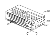
Figure 1A illustrates and can be used for the part of the optical thin film structure 101 of technology hereinafter described.Shown in optical thin film 101 can be described with axle x, y and the z of three mutually orthogonals.In an illustrated embodiment, axle x and the y of two quadratures is in film 101 planes (in the face, or x axle and y axle), and the 3rd (z axle) then extends in the film thickness direction.In some exemplary embodiments, optical thin film 101 comprises at least two kinds of different materials, i.e. first material and second material (as two kinds of materials of formation such as the optical effects such as reflection, scattering, transmission that combine) that connects with optical interface.In exemplary embodiments of the present disclosure, one or both are arranged in two kinds of materials is polymkeric substance.First material and second material can be selected as making and form required refractive index mismatch going up along at least one direction (as the MD direction) of film 101.Described material also can be selected as making going up in the direction (as along the TD direction) along at least one vertical with the refractive index mismatch direction of film 101 and form required refractive index match.
At least a material must form negative or positive birefringence under given conditions.Although also can use casting film, the material that is used for optical thin film is preferably possesses enough similar rheological characteristics, to satisfy the requirement of coextrusion process.In other exemplary embodiments, optical thin film 101 can only be made of a kind of material or can constitute by miscible blend by two or more materials.This type of exemplary embodiment can be used as retardation plate or the compensating plate in the optical display.
Optical thin film 101 can be by comprising that the processing film method that film draws operation forms.May cause film under the situation that is widened or elongating film under the situation that is widened, having the strain inducing orientation under the situation of no strain inducing orientation, to produce the strain inducing orientation drawing film under the different processing conditionss.The molecular orientation of being induced can be used to (for example) and change the refractive index of affected material on drawing direction.Can control the degree of molecular orientation of inducing according to the film desired properties, hereinafter will be described in further detail by drawing.
It is incomplete same that term " birefringence " is illustrated in x, y and the refractive index on the z direction of quadrature.With regard to polymeric layer as herein described, axle is selected as making x axle and y axle in the plane of this layer, and the z axle is corresponding to the thickness direction or the short transverse of this layer.Term " birefraction in the face " is interpreted as the difference of refractive index in interior refractive index of largest face and the minimal face, as refractive index n in the face
xWith n
yDifference.Term " the outer birefraction of face " is interpreted as one of interior refractive index of face (as n
xOr n
y) and the outer refractive index n of face
zDifference.Except as otherwise noted, otherwise the value of all birefractions announced and refractive index all at the light of 632.8nm.
Exemplary embodiment of the present disclosure can be a feature with " effectively axis of orientation ", and this effective axis of orientation is that refractive index changes direction in the maximum face in response to becoming induced orientation.For example, effectively axis of orientation overlaps with the obstruction axle of reflective or absorption polarization film usually.Usually, at refractive index in the face two main shafts are arranged, they are separately corresponding to largest refractive index value and minimum refractive index value.For wherein at along the light of major axes orientation or draw direction polarization, the positive birefringence material that refractive index is tended to increase, effective spool the overlapping of refractive index in axis of orientation and the largest face.At along the light of major axes orientation or draw direction polarization, the negative birefringence material that refractive index is tended to reduce, effectively axis of orientation will overlap with the axle of refractive index in the minimal face to wherein.
Optical thin film 101 forms with two or more different materials usually.In some exemplary embodiments, optical thin film of the present disclosure comprises only a kind of birefringent material.In other exemplary embodiments, optical thin film of the present disclosure comprises at least a birefringent material and at least a isotropic material.In other exemplary embodiments, optical thin film comprises first birefringent material and second birefringent material.In this type of exemplary embodiment, refractive index produces similar variation in the face of two kinds of materials under identical process conditions.In one embodiment, when film is drawn, first material and second material all should increase the refractive index along the light of drawing direction (as the MD direction) polarization, to then reducing along the refractive index perpendicular to the light of direction (as the TD direction) polarization of draw direction.In another embodiment, when film is drawn, first material and second material all should reduce the refractive index along the light of drawing direction (as the MD direction) polarization, to then increasing along the refractive index perpendicular to the light of direction (as the TD direction) polarization of draw direction.Usually, under a kind of, two or more birefringent materials were used for situation according to orientation optical thin film of the present invention, effective axis of orientation of every kind of birefringent material was all consistent with the MD direction.
When the refractive index that causes two kinds of materials by the formed orientation of combination of drawing step or drawing step coupling and in another side on the direction during basic mismatch, this film is specially adapted to make reflective polarizer on the direction in a face.The transmission of the direction formation polaroid of coupling (by) direction, and the direction of mismatch forms reflection (obstruction) direction.In general, refractive index mismatch must be many more on reflection direction, and refractive index match must be approaching more on transmission direction, and then the performance of polaroid is good more.
Figure 1B shows multilayer optical film 111, and it comprises the ground floor of first material 113, and this first material 113 is set on the second layer of (as by the co-extrusion mode) second material 115.Any in first material and second material or two kinds all can be birefringence.Although in Figure 1B, only illustrate two-layer, and also carry out the generality explanation in this article, but this technology is equally applicable to have the multilayer optical film of being made by the different materials of any kind of number that mostly is hundreds of layers or thousands of layers or more multi-layered (as a plurality of ground floors of first material 113 and a plurality of second layers of second material 115) most by two-layer.Multilayer optical film 111 or optical thin film 101 can comprise extra play.Extra play can be optical (as the optical function of realizing adding), also can right and wrong optical (as for its mechanical property or chemical property and select this extra play).As the U.S. Patent No. 6 that is incorporated herein with way of reference, 179,948 discussed like that, these extra plays can be orientated under process conditions as herein described, and can help to realize the whole optical property and/or the mechanical property of film, but be clear and for simplicity, in present patent application, will these layers be further discussed.
Material in the optical thin film 111 is selected as having viscoelastic property, so that the stretch behavior of two kinds of materials 113 in the film 111 and 115 is to the small part onrelevant.For example, in some exemplary embodiments, two kinds of materials 113 and 115 pairs are stretched or the response of drawing between onrelevant be favourable.By making the onrelevant between the behavior that draws of two kinds of different materials, can distinguish the control material change of refractive, with state of orientation and the various combinations of birefringence level accordingly that obtain two kinds of different materials.In this type of technology, two kinds of different materials constitute the optical layers of multilayer optical film (as the co-extrusion multilayer optical film).Though the refractive index of each layer can have initial isotropy (promptly the refractive index along each is all identical), can be specially in extrusion film or introduce a little orientation in the casting process by way of parenthesis.
A kind of mode that forms reflective polarizer is used second material because of processing according to the present invention possesses first material of birefringence and refractive index keeps isotropy (promptly not forming measurable birefringence value) substantially in drawing work.In some exemplary embodiments, have after second material is selected as drawing with first material non-and draw the refractive index that refractive index is complementary in the face of state.
The material that is applicable to optical thin film among Figure 1A, Figure 1B is discussed in (for example) U.S. Patent No. 5,882,774 to some extent, and described patent is incorporated this paper by reference into.The material that is suitable for comprises the polymkeric substance such as copolyesters such as polyester, copolyesters and modification.In this article, term " polymer " " should be understood to include homopolymer and multipolymer and can form can miscible blend form (as by coextrusion or comprise that the reaction of ester exchange reaction realizes) polymkeric substance or multipolymer.Term " polymer " " and " multipolymer " comprise random copolymers and segmented copolymer.Be applicable to that the polyester in some exemplary optical film of optical body constructed according to the invention generally includes carboxylate subunit and glycol subunit, and can generate by the reaction of carboxylic acid ester monomer molecule and glycol monomer molecule.Each carboxylic acid ester monomer molecule all has two or more carboxylic acid functionals or ester functional group, and each glycol monomer molecule all has two or more hydroxy functional groups.The carboxylic acid ester monomer molecule can all identically maybe can be two or more different types of molecules.The situation of glycol monomer molecule is identical.Term " polyester " also comprise by the reaction of glycol monomer molecule and carbonic ester derive and polycarbonate.
The carboxylic acid ester monomer molecule that is applicable to the carboxylate subunit that forms polyester layer comprises (for example): 2, and 6-naphthalene dicarboxylic acids and isomeride thereof; Terephthalic acid (TPA); M-phthalic acid; Phthalic acid; Azelaic acid; Hexane diacid; Decanedioic acid; Norbornene dicarboxylic acids; Bicyclooctane dicarboxylic acids; 1,6-cyclohexane dicarboxylic acid and isomeride thereof; Tert-butyl isophthalic acid, trimellitic acid, sulfonation m-phthalic acid sodium; 2,2 '-diphenyl dicarboxylic acid and isomeride thereof; And these sour lower alkyl esters, for example: methyl esters or ethyl ester.In this article, term " low alkyl group " refers to the alkyl of C1-C10 straight or branched.
The glycol monomer molecule that is applicable to the glycol subunit that forms polyester layer comprises: ethylene glycol; Propylene glycol; 1,4-butylene glycol and isomeride thereof; 1, the 6-hexanediol; Neopentyl glycol; Polyglycol; Diglycol; Three ring decanediols; 1,4 cyclohexane dimethanol and isomeride thereof; The norcamphane glycol; Two ring ethohexadiols; Trimethylolpropane; Pentaerythrite; 1,4-benzene dimethanol and isomeride thereof; Bisphenol-A; 1,8-dihydroxybiphenyl and isomeride thereof; And 1,3-two (2-hydroxy ethoxy) benzene.
The exemplary polymer that can be used in the optical thin film of the present disclosure is PEN (PEN), and it can react by (for example) naphthalenedicarboxylic acid and ethylene glycol and make.Gather 2,6-(ethylene naphthalate) (PEN) often is selected as first polymkeric substance.PEN has bigger positive stress optical coefficient, can effectively keep birefringence after stretching, and very little or do not have an absorbance at the visible-range internal absorbance.PEN also has higher refractive index under isotropic state.It is to the refractive index of the polarized incident light under the 550nm wavelength, be increased to up to about 1.9 from about 1.64 when being parallel to draw direction in the plane of polarization.Increase the birefraction that molecular orientation can increase PEN.By with material extending to bigger draw ratio and keep other stretching conditions constant, can increase molecular orientation.Other hemicrystalline polyester that are suitable as first polymkeric substance comprise that (for example) is poly-2,6-naphthalenedicarboxylic acid butanediol ester (PBN), polyethylene terephthalate (PET) and multipolymer thereof.
In some exemplary embodiments, second polymkeric substance of second optical layers should be selected as making that refractive index on its at least one direction and the refractive index of first polymkeric substance on same direction have significant difference in the final film that forms.Because polymeric material has dispersivity (that is to say, its refractive index can with wavelength variations) usually, so should consider these conditions at the concrete spectral bandwidth of being paid close attention to.Should be appreciated that from above-mentioned discussion the expection application of the multilayer optical film of being considered is not only depended in the selection of second polymkeric substance, also depends on selection and processing conditions that first polymkeric substance is done.
Be applicable to optical thin film, especially be suitable as the other materials of first polymkeric substance of first optical layers in (for example) U.S. Patent No. 6,352,762 and 6,498,683 and U.S. Patent application No.09/229724,09/232332,09/399531 and 09/444756 in describe to some extent, described patent documentation is incorporated this paper by reference into.The another kind of polyester that can be used as first polymkeric substance is to have derived from the carboxylate subunit of 90 moles of % naphthalene diformic acid dimethyl esters and 10 moles of % dimethyl terephthalate (DMT) and is the coPEN of 0.48 deciliter/gram derived from the glycol subunit and the limiting viscosity (IV) of 100 moles of % ethylene glycol subunits.The refractive index of this polymkeric substance is about 1.63.Described polymkeric substance is called as low melting point PEN (90/10) in this article.The another kind of first available polymkeric substance be can buy from Eastman Chemical (Eastman Chemical Company, this baud city of tennessee,USA gold), limiting viscosity is the PET of 0.74 deciliter/gram.The polymkeric substance of non-polyester also can be used for forming the polaroid film.For example, polyetherimide can cooperate such as the use of polyester such as PEN and coPEN, to form multilayer mirror.Also can use other polyester/non-polyester combination, as polyethylene terephthalate and tygon (as can buy from Michigan, USA Midland Dow Chemical (DowChemical Corp.), commodity Engage 8200 by name those).
Second optical layers can be compatible to the glass transition temperature of first polymkeric substance by glass transition temperature and multiple polymers that refractive index is similar to the isotropic refractive index of first polymkeric substance make.Except that above-mentioned CoPEN polymkeric substance, be applicable to that optical thin film, the especially example of other polymkeric substance of second optical layers comprise polyvinyl and the multipolymer of making by such as monomers such as vinyl naphthalene, styrene, maleic anhydride, acrylate and methacrylates.The example of this polymkeric substance comprises polyacrylate, polymethacrylate (for example, polymethylmethacrylate (PMMA)) and isotactic polystyrene or syndiotactic polystyrene.Other polymkeric substance comprise such as condensed polymers such as polysulfones, polyamide, polyurethane, polyamic acid and polyimide.In addition, second optical layers can be made by polymkeric substance such as polyester and polycarbonate and multipolymer.
Other exemplary suitable polymers (particularly being applicable to the polymkeric substance of second optical layers) comprising: the homopolymer of polymethylmethacrylate (PMMA) (as the product that can buy from Wilmington City, Delaware, USA State Ineos acryl resin company (Ineos Acrylics), commodity are called CP71 and CP80), or glass transition temperature is lower than the polyethyl methacrylate (PEMA) of the glass transition temperature of PMMA.Second polymkeric substance in addition comprises: PMMA multipolymer (coPMMA), the coPMMA that generates as the coPMMA (can buy from Ineos acryl resin company (Ineos Acrylics), its commodity are called Perspex CP63) that makes by 75 weight % methyl methacrylate (MMA) monomers and 25 weight % ethyl acrylate (EA) monomers, by MMA comonomer unit and n-BMA (nBMA) comonomer unit; Or the blend of PMMA and polyvinylidene fluoride (PVDF), as can (Solvay Polymers Inc.) buys, the product of commodity Solef 1008 by name from Houston, TX, USA city Su Wei Polymer Company.
Other polymkeric substance (particularly being applicable to the polymkeric substance of second optical layers) that are suitable for comprise polyolefin copolymer, as buying from elastic body company of Tao Shi Du Pont (Dow-Dupont Elastomers), trade name be Engage 8200 poly-(ethene-co-octene) (PE-PO), can receive petrochemistry company (Fina Oil and Chemical Co.) from Texas, USA Dallas city's phenanthrene buys, commodity Z9470 by name gathers (propylene-co-ethene) (PPPE), and can buy from Salt Lake City, Utah, United States city Hensel chemical company (Huntsman Chemical Corp.) advanced in years, the atactic polypropylene (aPP) of commodity RexflexW111 by name and the multipolymer of isotactic polypropylene (iPP).Optical thin film (for example) can also comprise in second optical layers such as linear low density polyethylene-g-maleic anhydride functionalised polyolefins such as (LLDPE-g-MA), as from (the E.I.duPont de Nemours﹠amp of De Nei The Moore Co. of Wilmington City, Delaware, USA State E.I. Du Pont; Co., the product that Inc.) buy, commodity is called Bynel 4105.
The example combinations of polaroid material therefor comprises PEN/co-PEN, polyethylene terephthalate (PET)/co-PEN, PEN/sPS, PEN/Eastar and PET/Eastar, wherein " co-PEN " refers to multipolymer or the blend based on naphthalenedicarboxylic acid (as indicated above), and Eastar is can be from the poly terephthalic acid hexamethylene dimethyl ester of Eastman Chemical (Eastman Chemical Co.) purchase.The example combinations of catoptron material therefor comprises PET/coPMMA, PEN/PMMA or PEN/coPMMA, PET/ECDEL, PEN/ECDEL, PEN/sPS, PEN/THV, PEN/co-PET, PET/co-PET and PET/sPS, wherein " co-PET " refers to multipolymer or the blend based on terephthalic acid (TPA) (as indicated above), ECDEL is can be from the thermoplastic polyester of Eastman Chemical (EastmanChemical Co.) purchase, and THV then is can be from the fluoropolymer of 3M company purchase.PMMA refers to polymethylmethacrylate, and PETG then refers to use the PET multipolymer of second dibasic alcohol (being generally cyclohexanedimethanol).SPS refers to syndiotactic polystyrene.
In another embodiment, optical thin film can be maybe can comprise the blend optical thin film.In some exemplary embodiments, the blend optical thin film can be the diffuse reflection type polaroid.In according to typical blend film of the invention process, use the blend (or potpourri) of at least two kinds of different materials.Two or more materials can be used for making incident light along this polarization by scattering basically along the refractive index mismatch of specific axis, thereby cause the diffuse reflection of this light generation significant quantity.The incident light of the direction polarization of the axle that is complementary along the refractive index of two or more materials wherein is by transmission basically, or at least with much smaller scattering degree transmission.By the relative index of refraction of control material and other characteristics of optical thin film, can construct the diffuse reflection type polaroid.This type of blend thin films can show as many different forms.For example, the blend optical thin film can comprise one or more common external phases, the one or more disperse phase in one or more external phases or common external phase.The general formation method of various blend thin filmses and optical property be in U.S. Patent No. 5,825, further discusses in 543 and 6,111,696, and the disclosure of these patents is incorporated this paper into way of reference.
Fig. 2 show by first material and with the formed embodiment of the present disclosure of the blend of immiscible substantially second material of first material.In Fig. 2, optical thin film 201 is by continuously (matrix) mutually 203 and disperse (discontinuous) 207 formations mutually.External phase can comprise first material, and second can comprise second material mutually.The optical characteristics of this film can be used for making the diffuse reflection type polarization film.In such film, the refractive index of external phase and discrete state material is mated along axle in the face is basic, and along the basic mismatch of axle in another face.In general, there are one or both or to draw and form birefringence in the face in this material by the stretching under the appropraite condition.In diffuse reflection type polaroid (as shown in Figure 2), wish to make the refractive index of this material in a face of film, as far as possible closely to mate on the direction of principal axis, and in another face, have big as far as possible refractive index mismatch on the direction of principal axis.
If optical thin film is the blend thin films that comprises disperse phase and external phase as shown in Figure 2, or comprising first is total to external phase and second blend thin films of external phase altogether, and then many different materials can be used as external phase or disperse phase.These materials comprise such as inorganic material such as silicon-based polymer, such as organic materials such as liquid crystal and polymeric material (comprising monomer), multipolymer, graft polymer, and composition thereof or blend.In some exemplary embodiments, be selected in the blend optical thin film with diffuse reflection type polaroid characteristic as external phase and disperse phase or as the material of external phase altogether and can comprise: can under second group of processing conditions, be orientated, with lead-in surface in birefringent at least a optical material, and under second group of processing conditions, can not form tangible orientation and can not form tangible birefringent at least a material.
The details of selecting about the material of blend thin films are in U.S. Patent No. 5,825, set forth to some extent in 543 and 6,590,705, and these two patents are all incorporated this paper into way of reference.
The suitable material of external phase (it also can be used in the disperse phase in some structure or is used for common external phase) can be amorphous, hemicrystalline or crystalline polymeric material, comprise by such as isophathalic acid, azelaic acid, hexane diacid, decanedioic acid, dibenzoic acid, terephthalic acid (TPA), 2,7-naphthalenedicarboxylic acid, 2,6-naphthalenedicarboxylic acid, cyclohexane cyclohexanedimethanodibasic and diphenic acid (comprise 4,4 '-diphenic acid) material of making by carboxylic acid group's monomer, the perhaps material of making by the corresponding ester (as dimethyl terephthalate (DMT)) of above-mentioned acid such as.Comprising 2, the multipolymer of 6-PEN (PEN), PEN and polyethylene terephthalate (PET), PET, PTT, poly-naphthalenedicarboxylic acid propylene glycol ester, polybutylene terephthalate, PBN, poly terephthalic acid hexanediol ester, poly-naphthalenedicarboxylic acid hexanediol ester and the poly-naphthalate of other crystallinity.Because the ability that PEN and PET and composition have the birefringent character of strain inducing and keep permanent birefringence after stretching between the multipolymer between the two, so it is particularly preferred material.
In some film configuration, the suitable material of second polymkeric substance comprises: when being oriented under the condition that is being used to make first polymeric material produce suitable birefringence level, it is the material of isotropy or birefringence.The example that is fit to comprises: polycarbonate (PC) and Copolycarbonate; Polystyrene-poly methylmethacrylate copolymer (PS-PMMA); The PS-PMMA-acrylate copolymer can be the product of MS600 (acrylate content is 50%) and NAS21 (acrylate content is 20%) from Pennsylvania, America moon town (Moon Township) chemical company of Novartis (NovaChemical) purchase, trade name for example; The polystyrene-maleic anhydride multipolymer can be the product of DYLARK from the purchase of chemical company of Novartis, trade name for example; Acrylonitrile-butadiene-styrene (ABS) (ABS) and ABS-PMMA; Polyurethane; Polyamide is especially such as nylon 6, nylon 6,6 and nylon 6,10 fatty polyamides such as grade; SAN (SAN) is as the TYRIL that can buy from Michigan, USA Midland Dow Chemical (Dow Chemical) etc.; And polycarbonate/polyester blending resin, can be the polyester/polycarbonate alloy of Makroblend for example from Baeyer Plastics Company (Bayer Plastics) purchase, trade name, can be the product of Xylex from General Electric's Plastics Company (GEPlastics) purchase, trade name, and can be the product of SA 100 and SA 115 from Eastman Chemical (Eastman Chemical) purchase, trade name; Polyester for example comprises the aliphatic copolyester of CoPET and CoPEN; Polyvinylchloride (PVC) and polychlorobutadiene.
In one aspect, the disclosure relates to the method that a kind of preparation can be used for the wide cut orientation rolled web of optical film in (for example) optical display, and the effective axis of orientation that wherein is orientated optical thin film is consistent with the length direction of reel usually.This film (as the reflection type polarization film) reel can easily be laminated on other optical thin films (as absorption polarization film) reel of the blocked state axle that has along its length.
Illustrative methods of the present disclosure comprises to be provided by at least a polymeric material, the optical thin film preferably made by first polymeric material and second polymeric material at least, wherein have at least in the polymeric material a kind of can form dielectric grid.In first step, optical thin film is stretched on horizontal dimension (TD) direction or draws (be commonly referred to as first in this article and draw step), under first group of processing conditions, film is widened, make in film, only to form birefringence in the low face (if having formed birefringent words in the face).
Term as used herein " widens " and is meant that film dimensions is changed and does not introduce substantial molecular orientation in the polymer molecule that constitutes film, preferably do not introduce the operation of molecular orientation.When film is widened in first operation, should select process conditions (for example temperature), so that unacceptable inhomogeneous situation can not appear in film after first operation and second operation, and can satisfy the quality requirements of optical thin film.
Term as used herein " orientation " is meant the operation that film dimensions is changed and bring out molecular orientation in one or more polymeric materials that constitute described film.Be commonly referred to as second at this paper and draw in second operation of step, film is drawn along dimension (MD) direction second group of processing conditions lower edge, to bring out enough birefringences in the optical thin film at required being applied in.In addition, can be separately or draw step and second in conjunction with first and draw the additional stretching step of step application or draw step, with the optical property of improving film (as optical homogeneity, warpage, peel off tack, birefraction etc.).
Schematically show the illustrative processes of orientation optical thin film produced according to the present invention among Fig. 3.At first, provide optical thin film to device 300, this device 300 makes film stand to stretch or all to stand to stretch at both direction in horizontal dimension (TD) direction or along dimension (MD) direction as required.The stretching step that is applied to film can be carried out or carry out simultaneously in order.For example, device shown in Fig. 3 can comprise the magnetic drive chuck apparatus 302 of chain equipment or clamping films width of cloth edge edge.Each anchor clamps can be by computer control, to provide multiple stretching profile at film web material 304 at 300 o'clock by installing.
In the unshowned alternative embodiment of Fig. 3, optical thin film 304 can be stretched according to the profile by the varying pitch screw device control.Profile and relative quantity that screw rod control MD direction stretches, and be positioned on the guide rail in conjunction with other process conditions control TD profiles and stretching.In unshowned another embodiment of Fig. 3, optical thin film 304 can be stretched according to the profile by mechanical pantograph-guide track system control, wherein each spacing jig of partly controlling the MD draw ratio is controlled by mechanical pantograph, in described mechanical pantograph, the TD draw ratio partly by anchor clamps the guide rail path of process control.Be applicable to some illustrative methods and the U.S. Patent No. 3 of device of the oriented film according to the present invention Kemp husband (Kampf), 150,433 and the U.S. Patent No. 4,853 of Huo Meisi (Hommes), describe to some extent in 602, these two patents are all incorporated this paper into way of reference.The film 304 that infeeds in the device 300 can be the solvent cast film or extrude casting film.In the embodiment shown in fig. 3, film 304 is the extrusion film of being discharged by mould 306, and comprises at least a, two kinds of polymeric materials preferably.Optical thin film 304 can be used according to expection wide in range variation, and can have monolithic construction, the hierarchy shown in Figure 1B or blend structure as shown in Figure 2 shown in Figure 1A, or their combination.
Preferably, before implementing follow-up drawing work, the material that is selected for optical thin film 304 should be without any the orientation that does not expect to have.Alternatively, in casting step or extrusion step, can bring out orientation wittingly, with as first auxiliary process of drawing step.For example, casting step or extrusion step can be regarded as first and draw the ingredient of step.Material in the film 304 is selected according to the final application of optical thin film, and after all draw step in enforcement, this material will form birefringence in the face, and can have such as reflection characteristics such as reflection type polarization characteristics.In the exemplary embodiment that present patent application described in detail, the material of the optics boundary in the film 304 is selected as at the film that possesses the reflective polarizer characteristic through formation after all orientation step.
Again referring to Fig. 3, in case after optical thin film 304 was extruded or otherwise provided from mould 306, optical thin film 304 was promptly drawn first by the suitable chuck apparatus 302 at clamping films 304 edges and stands in the step to stretch in zone 310.First draws step carries out under first group of processing conditions (drawing at least one condition in temperature, drawing speed and the drawing ratio (as the ratio of TD/MD drawing speed)), so that film 304 becomes wideer in horizontal dimension (TD) direction.Should select first group of processing conditions, make that any additional birefraction of bringing out in the film is less: draw in the step first, polymeric material planted agent in film 304 only brings out slight birefringence, preferably do not bring out birefringence substantially, and most preferably do not bring out birefringence.In some exemplary embodiments, after first drew step, birefraction was less than about 0.05, preferably less than about 0.03, more preferably less than about 0.02, most preferably less than about 0.01 in the face.
Polymeric material produces the tendency of orientation by due to the viscoelasticity behavior of polymkeric substance under one group of given processing conditions, and the viscoelasticity behavior normally causes because of the molecular relaxation speed of polymeric material.Molecular relaxation speed can be characterized by average the longest whole slack time (being that molecule is whole resets) or distribution that should the time.On average can increase with decrease of temperature usually the longest slack time, and when approaching glass transition temperature, reach great value.The longest average slack time also can be because of crystallization in the polymeric material and/or crosslinked increasing, for practical purposes, and crystallization and/or crosslinkedly under normally used process time and temperature, can suppress any lax of this long pattern.Molecular weight and distribution and chemical composition and structure (as grafting) also can influence the longest slack time.
When approximate or draw the time greater than technology the on average the longest slack time of particular polymers material, at the drawing direction of material substantial molecular orientation will appear.Therefore, high strain rate and low strain rate correspond respectively to less than or greater than the longest average slack time in draw this material technology.The response of given material can drawing temperature, drawing speed and drawing change recently by CONTROL PROCESS.
Degree of orientation in the drawing work can be controlled in relative broad range exactly.In some drawing work, in fact drawing work may reduce the degree of molecular orientation of film at least one direction.On drawing direction, the scope of the molecular orientation that is brought out by drawing work is from basic not orientation, be changed to slight optical orientation (as the negligible orientation of influence that the Film Optics performance is produced), be changed to optical orientation that can remove, in various degree in subsequent handling.
The relative intensity of optical orientation depends on the relative index of refraction of material and film.For example, stronger optical orientation may be relevant with the birefraction total, intrinsic (normalization) of given material.Alternatively, draw intensity may with given drawing operation in, the total amount of the difference of accessible normalization refractive index is relevant between the material.The degree of molecular orientation that should also be appreciated that appointment may be regarded as strong optical orientation under a certain situation, then may be regarded as weak optical orientation in another case or not have the optics orientation.For example, in second between axle and the face outer shaft, have under the situation of very large birefraction, in first spool and a certain amount of birefraction between the face outer shaft can be regarded as low birefraction.In the short period that is enough to bring out a little or a large amount of optical molecular orientation of at least a material production that optical thin film of the present disclosure comprises and/or the technology of carrying out under the lower temperature be respectively weak optical orientation drawing work or strong optical orientation drawing work.Be enough in the long period of less molecular orientation make taking place or molecular orientation not taking place and/or the technology of carrying out under the higher temperature is respectively the more weak technology of optical orientation or does not have the technology of optics orientation substantially.
By considering that orientation/non-orientation response that one or more materials produce process conditions selects material and process conditions, can at every kind of material separately control along each draw step spool the degree of orientation (if any orientation is arranged).Yet, himself might not control the molecular orientation of final film by the degree of molecular orientation that a certain concrete drawing work is induced.Can in first drawing work, carry out the orientation of non-optical effective dose, with compensation or help in second drawing work or the follow-up drawing work further molecular orientation to a kind of material.
Although drawing work is limited to first approximation with the change in orientation amount in the material, also may influence the orientation characteristic such as densification or phase transformation auxiliary processes such as (as crystallizations).Under the situation of extreme material interaction (as molecule self assembly or liquid crystal phase transition), these influences may play a major role.For example, in typical case, the polymer molecule main chain is tended to the quilt that streamwise arranges draw polymkeric substance, often only orientation characteristic is had minor effect such as effects such as strain inducing crystallizations.Yet strain inducing crystallization and other crystallizations have appreciable impact (drawing as weak orientation being drawn become strong orientation) really to the intensity of this type of orientation.Therefore, two kinds of materials that are selected in the optical thin film 304 all can not rapid crystallization, and one of material tangible crystallization can not occur under being applied to the first first group of processing conditions that draws in the step.Therefore, in some applications, the crystallization rate coPEN (as the multipolymer of PEN and PET) slower than PEN may be preferred under first group of processing conditions.The example that is suitable for is 90% PEN and the multipolymer of 10%PET, is referred to herein as low melting point PEN (LmPEN).
According to one or more polymkeric substance that constitute film 304, the first first group of processing conditions that draws in the step may alter a great deal.Usually under temperature height, drawing ratio is low and/or strain rate is low condition, polymkeric substance tends to flow as viscous liquid when being drawn, and molecular orientation seldom or not takes place the molecular orientation of this polymkeric substance.Under and/or the condition that strain rate is high low in temperature, polymkeric substance tends to carry out elasticity as solid and draws, and molecular orientation takes place simultaneously.Low temperature process is usually less than, preferably approaches the glass transition temperature of amorphous polymer materials, high-temperature technology then usually above, preferably apparently higher than glass transition temperature.Therefore, should under high temperature (being higher than glass transition temperature) and/or low strain rate condition, carry out first usually and draw step, to form molecular orientation seldom or not form molecular orientation.In exemplary embodiments of the present disclosure, to draw in the step first, temperature should be enough high, so that tangible orientation can not take place in polymkeric substance, but should be not too high, to such an extent as to cause one or more polymkeric substance generation stationary crystallizations of optical thin film.Stationary crystallization is regarded as disadvantageous sometimes, and is because it may cause the optical characteristics that is harmful to, too high as mist degree.In addition, the heated time of film (being heating rate) should be adjusted to and avoid the orientation that occurs not expecting to have.
For example, shown in Figure 1B, with in the optical thin film of PEN as high-index material, first temperature of drawing step be in glass transition temperature than at least a polymkeric substance in the optical thin film (being all polymkeric substance in the optical thin film sometimes) high about 20 ℃ to about 100 ℃ scope.In some exemplary embodiments, first temperature of drawing step be in than the glass transition temperature of at least a polymkeric substance in the optical thin film (being all polymkeric substance in the optical thin film sometimes) high about 20 ℃ to about 40 ℃ scope.
First drawing in the step of using first processing conditions, for example in zone shown in Figure 3 310, film 304 preferably is stretched or draws in horizontal dimension (TD) direction.Yet, when horizontal dimension (TD) direction stretches/draws, film 304 also can randomly be stretched along dimension (MD) direction or draw, that is to say, as long as in the polymeric material of film 304, only introduce birefringence in the low face (as introducing birefringence in the slight face, preferably there is not birefringence in the lead-in surface substantially, more preferably there is not birefringence in the lead-in surface), then film can carry out biaxial stretch-formed or twin shaft draws, perhaps film 304 can also be stretched along the MD direction after the TD direction is stretched again.
After film 304 is used first group of processing conditions, draw in the step in other (often for follow-up) second, in zone shown in Figure 3 320, film is used second group of processing conditions.Draw in the step second, optical thin film 304 is along being drawn along dimension (MD) direction, make and bring out birefringence at least a polymeric material in this film, and make that after second drew step, effective axis of orientation of described at least a birefringent material was positioned on the MD direction.Comprise among the embodiment of first polymeric material and second polymeric material at optical thin film, preferably bring out between first material and second material refractive index mismatch take place along axle (as a MD direction) in first, and along and first in do not bring out substantially between first material and second material on (as TD) direction in second of axle quadrature refractive index mismatch take place.In some exemplary embodiments, axle overlaps with effective axis of orientation in first.
In some exemplary embodiments, draw in the face of introducing in the step birefraction second and be at least approximately 0.06, be at least approximately 0.07, preferably be at least approximately 0.09, more preferably be at least approximately 0.11, even more preferably be at least about 0.2.In the exemplary embodiment that comprises first polymeric material and different with it second polymeric material at least, after described second draws step, first material and second material can be at least about 0.05 along the difference of refractive index in the face of MD direction, preferably be at least about 0.1, more preferably be at least approximately 0.15, most preferably be at least about 0.2.More in general, for the situation of reflective polarizer, wish in the refractive index mismatch value that does not obviously reduce the situation lower edge MD direction of performance aspect other of optical thin film big as far as possible.These performances can by the following stated with second draw step and carry out simultaneously or be improved in the additional step/technology of carrying out thereafter.
In addition, in the exemplary embodiment that comprises first polymeric material and different with it second polymeric material at least, after second draws step, first material and second material can be less than about 0.03 along the difference of refractive index in the face of TD direction, more preferably less than about 0.02, most preferably less than about 0.01.In other exemplary embodiments, these conditions may first draw step and second draw step after or any additional process after satisfied.
Great changes have taken place though the detail of second group of processing conditions possibility basis is selected for the material of optical thin film 304, but second group of processing conditions generally includes the temperature that is lower than first group of processing conditions, and can comprise higher drawing speed and/or drawing ratio.For example, shown in Figure 1A, with PEN as high-index material and in the layering optical thin film of coPEN as low-index material, second draw the temperature of using in the step should be in than optical thin film in the glass transition temperature of polymeric material low about 10 ℃ to being higher than in the about 60 ℃ scope of this glass transition temperature.For example, in order to prepare reflective polarizer, after second drew step, the difference (if any difference is arranged) of the refractive index (as (TD) direction in face) of hope coupling usually was less than about 0.05, more preferably less than about 0.02, most preferably less than about 0.01.In direction of error ((MD) direction in as face), it is about 0.06 that the difference of wishing refractive index usually is at least, more preferably greater than about 0.09, even more preferably greater than about 0.11.More in general, wish under the condition that does not significantly reduce performance aspect other of optical thin film, to make this difference big as far as possible.
In some exemplary embodiments, device finish in 300 second draw step after, can process film 304 by the required additional step of drawing of concrete application.Second draws step or additional draw step and can perhaps film can be removed and be transferred to another different production line from production line 300 along carrying out on the LO of same production line, and adopts volume to volume technology to be introduced among the LO.If desired, can in second step or additional step, change the birefraction of film.Second draw step and/or additional draw step after, can be randomly with any order to film or any layer or the film arranged thereon implement corona treatment, prime or drying steps in any operation or all operation handle, to strengthen its surface property, for example at the surface property of follow-up laminated step.
In the exemplary means 440 of as shown in Figure 3A another embodiment of the present invention, optical thin film 452 is extruded from mould 450, or otherwise be sent to the remainder of device, and and draw in the step first, in the zone 442 of stenter 454, be stretched or draw along the TD direction.In the embodiment shown in Fig. 3 A, first draws step carries out under first group of processing conditions (drawing at least one condition in temperature, drawing speed and the drawing ratio (as the ratio of TD/MD drawing speed)), make in the polymeric material of film, only to induce and produce birefringence in the low face, perhaps only induce and produce birefringence in the slight face, preferably do not induce birefringence in the generation face substantially, most preferably do not induce birefringence in the generation face.Next, film draws in the step second and carries out length orientation by the equipment of being made up of low speed roller 456 and high speed roller 458 along the MD direction.Second draws step carries out under second group of processing conditions (drawing at least one condition in temperature, drawing speed and the drawing ratio (as the ratio of TD/MD drawing speed)), make and at least a polymeric material of film, induce birefringence in the face, to form effective axis of orientation along the MD direction.Second draw step before or after, can be randomly with any order to film or any layer or the film arranged thereon implement corona treatment, prime or drying steps in any operation or all operation handle, to strengthen its surface property at follow-up laminated step.
Though in the above-described embodiments various drawing work examples concrete order, should order only explain for convenience, and be not to plan to limit.In some cases, as long as follow-up technology of carrying out can not cause negative effect to the technology of carrying out before, the order of described technology can be changed or carry out simultaneously.For example, as mentioned above, optical thin film can be drawn on both direction simultaneously.When film when simultaneously axle draws in two faces, the temperature of drawing of the material in the film is identical.Yet drawing ratio and draw speed and can be controlled separately.For example, film can draw on the MD direction relatively quickly, draws on the TD direction then relatively slowly.
Can suitably select the drawing ratio that material, twin shaft draw simultaneously and draw speed, make that drawing the drawing of axle (as drawing fast) along first draws an optical orientation with one or both materials along first, then do not make one of two kinds of materials draw axle orientation (or not having the optics orientation) along second along draw (as drawing at a slow speed) of other direction.Therefore, the response that each direction is drawn of two kinds of materials can be independently controlled.
Effective axis of orientation of having carried out being used to making one or more birefringent materials that comprise in the orientation optical thin film realize second of above-mentioned MD orientation draw step or the 3rd draw step or any number of times be suitable for additional draw step after, the orientation optical thin film can be laminated on the multiple material, or otherwise with multiple combination of materials, to prepare various optical configurations, some structures wherein can be used for display device, as LCD.Orientation optical thin film of the present disclosure or comprise that any suitable laminated structure of orientation optical thin film of the present disclosure can be advantageously provides with the form of reel.
For example, above-mentioned any polarization film all can with the frlml laminating of surface structuration or otherwise placed on it, described surface structuration film for example can be buied from the 3M company of Saint Paul City, State of Minnesota, US, its commodity are called BEF.In one embodiment, the surface structuration film comprises the arrangement of substantially parallel linear prismatic structures or groove formation.In some exemplary embodiments, optical thin film 304 can be laminated on the surface structuration film, and described surface structuration film comprises the arrangement of substantially parallel linear prismatic structures or groove formation.This groove can be along arranging along dimension (MD) direction (at effective axis of orientation in reflective polarizer situation lower edge or obstruction axle), and perhaps this groove can be along horizontal dimension (TD) direction (along the axis of homology of reflective polarizer film or by axle) arrangement.In other exemplary embodiments, the groove of exemplary surface structuration film can become another angular orientation with respect to effective axis of orientation of orientation optical thin film of the present invention.
Those of ordinary skill in the art will recognize easily that patterned surface can comprise structure, rough surface or the mat surface of other any kinds.This type of exemplary embodiment can also prepare by introducing following additional step: apply the curing type material on optical thin film of the present disclosure, give the curing type material layer with surface structure, and the curing type material layer is solidified.
Because the exemplary reflective polarizer according to technology described herein preparation has along the obstruction axle along dimension (MD) direction, so reflective polarizer can be simply is laminated in any on the polarization film of length orientation in the mode of volume to volume.In other exemplary embodiments, film of the present invention can with absorption polarizer material layer (as the dichroic dye material or contain the layer of PVA) coextrusion mold, or be coated with before drawing step and be covered with such material carrying out second.
Fig. 4 illustrates optical thin film structure 400, wherein first optical thin film 401 (for example: have along the reflective polarizer of the obstruction axle of direction 405) and 403 combinations of second optical thin film.Second optical thin film 403 can be the optical thin film or the non-optical film of another kind of type, for example, has along the absorption polaroid of the obstruction axle of direction 404.
In structure shown in Figure 4, the obstruction axle 405 of reflection type polarization film 401 should be aimed at the obstruction axle 404 of dichroic polarizing film 403 as far as possible exactly, to provide acceptable performance at specific application (for example, blast polaroid).The reflection type polarization film pass through axle or the axis of homology is marked as 406.The degrees of misalignment increase of axle 404,405 can reduce the gain that laminated structure 400 is produced, and laminated structure 400 not too is suitable in some display application.For example, for the blast polaroid, the angle between the obstruction axle 404,405 of structure in 400 should less than approximately+/-10 °, more preferably less than approximately+/-5 °, more preferably less than approximately+/-3 °.
In the embodiment shown in Fig. 5 A, laminated structure 500 comprises absorption polarization film 502.In this exemplary embodiment, absorption polarizing coating comprises first protective seam 503.Protective seam 503 can great changes have taken place according to the expection application, but generally include cellulose triacetate (TAC) film of solvent cast.Representative configuration 500 also comprises second protective seam 505 and absorption layer of polarizer 504, as the polyvinyl alcohol (PVA) (I of iodine staining
2/ PVA).In other exemplary embodiments, polarizing coating can only comprise a protective seam or not have protective seam.Available (for example) adhesive phase 508 is laminated in absorption polarizing coating 502 on (or otherwise be bonded in or place) optical thin film reflective polarizer 506 (as described herein have MD block those of axle).
In absorption polarizing coating of the present disclosure, can use any suitable absorption polarized material.For example, except that polyvinyl alcohol (PVA) (I based on iodine staining
2Outside/PVA) the polaroid, the disclosure contains: based on poly-(1,1-) light polarization plate of ethenylidene (is called as KE type polaroid, it is in U.S. Patent No. 5,973, have in 834 and further describe, this patent is incorporated this paper into way of reference), based on the polaroid of iodine, PVOH polaroid and other absorption polaroids that is suitable for of dyeing.
Fig. 5 B illustrates the exemplary polaroid collocation structure 510 that is used for optical display, and the bonding agent 512 that wherein laminated structure 500 usefulness are generally contact adhesive (PSA) is bonded on the optional birefringent film 514 (for example, compensation film or retardation plate film).In collocation structure 510, any one deck in the protective seam 503,505 all can randomly be used with the identical or different birefringent film (as compensating plate or retardation plate) of compensation film 514 and substitute.This type of optical thin film can be used in the optical display 530.In this class formation, compensation film 514 can stick on the panel of LCD 520 by adhesive phase 516, and panel of LCD comprises first glassy layer 522, second glassy layer 524 and liquid crystal layer 526.
Referring to Fig. 6 A, the laminated structure 600 that it shows another kind of example includes single protective seam 603 and absorption polarization layer 604 (as I
2/ PVA layer) absorption polarizing coating 602.Absorption polarizing coating 602 is bonded on the optical thin film reflective polarizer 606 of MD polarization axle by (for example) adhesive phase 608.In this exemplary embodiment, the obstruction axle of absorption polaroid is also along the MD direction.Dispense any one deck in the protective seam adjacent with absorption layer of polarizer 604 or two-layerly can provide many advantages, it comprises that (for example) thickness reduces, material cost reduces and to weaken (the TAC layer that does not need solvent cast) of environmental impact.
Fig. 6 B illustrates the polaroid collocation structure 610 that is used for optical display, and wherein laminated structure 600 usefulness bonding agents 612 are bonded on the optional birefringent film 614 (for example, compensation film or retardation plate film).In collocation structure 610, protective seam 603 can randomly be used with the identical or different birefringent film of compensation film 614 and substitute.This type of optical thin film can be used in the optical display 630.In this class formation, birefringent film 614 can stick on the panel of LCD 620 by adhesive phase 616, and this panel of LCD comprises first glassy layer 622, second glassy layer 624 and liquid crystal layer 626.
Fig. 6 C illustrates the exemplary polaroid collocation structure 650 that another kind is used for optical display.Collocation structure 650 comprises having single protective seam 653 and absorption layer of polarizer 654 (as I
2/ PVA layer) absorption polarizing coating 652.Absorption polarizing coating 652 is bonded on the reflective polarizer 656 that MD blocks axle in collocation structure 650 by (for example) adhesive phase 658, and protective seam 653 can randomly be substituted by compensating plate or retardation plate film.In order to form optical display 682, absorption layer of polarizer 654 can stick on the panel of LCD 670 by adhesive phase 666, and this panel of LCD comprises first glassy layer 672, second glassy layer 674 and liquid crystal layer 676.
Fig. 7 illustrates the exemplary polaroid collocation structure 700 that another kind is used for optical display, and wherein said absorption polarizing coating comprises without any the absorption polarizer material of the individual layer of adjacent protective seam (as I
2/ PVA) layer 704.Layer 704 a first type surface is bonded on the optical thin film reflective polarizer 706 that MD blocks axle, makes the obstruction axle of absorption polaroid equally also along the MD direction.Can realize bonding with adhesive phase 708.Another facing surfaces of layer 704 is bonded on the optional birefringent film 714 (for example, compensation film or retardation plate film) with bonding agent 712.This type of optical thin film can be used in the optical display 730.In this type of exemplary embodiment, birefringent film 714 can stick on the panel of LCD 720 that comprises first glassy layer 722, second glassy layer 724 and liquid crystal layer 726 by adhesive phase 716.
Adhesive phase among above Fig. 5-Fig. 7 can be used according to expection very cataclysm, but expects contact adhesive and the H that is mixed with PVA
2O solution is applicable to I
2/ PVA layer directly sticks on the reflective polarizer.Routine techniquess such as use such as air corona, nitrogen corona, other coronas, flame or primer coating layer can use separately one in reflective polarizer film and the absorption polaroid film or these two optional surface treatment of carrying out, perhaps cooperate bonding agent to use, to provide or to strengthen bond strength between each layer.This type of surface treatment can be drawn step and second together with first and be drawn that step is online carries out, or be regarded as independent step, and can be before first draws step, second draw step before, first draw step and second draw step after or any additionally carry out after drawing step.In other exemplary embodiments, absorption polarizer material layer can with exemplary optical film coextrusion mold of the present disclosure.
Following example comprises according to the exemplary materials of different embodiment of the present disclosure and processing conditions.These examples are not to plan the restriction disclosure, and just in order to help understanding the present invention, and the examples of materials that especially is suitable for according to above-mentioned various embodiment is provided.Those of ordinary skill in the art will recognize easily, to Fig. 5-exemplary embodiment shown in Figure 7, and can be according to the mode change that meets disclosure spirit.For example, the above-mentioned layer or the film of any suitable quantity or array mode all can use in exemplary embodiment of the present disclosure.
Example
In following example, sample is heated and stretched 10 to 60 seconds, decides on the situation of concrete material.Be 30 to 50 seconds modal heat time heating time.Draw in the step first, the film per second is stretched 10 to 60%, more generally is that per second is stretched 20 to 50%.Draw in the step second, the film per second is stretched 40 to 150%, more generally is that per second is stretched 60 to 100%.Term " initially " and " finally " are respectively applied for and refer to first and draw step and second and draw step.
Example 1
Processing conditions stretching individual layer PEN casting film according to following table 1 defined.
Table 1
| Sample | Initial TD direction | Final TD direction | Initial MD direction | Final MD direction | Incipient extension temperature ℃ | Final draft temperature ℃ | n md | n td | n zd | Δn MD-n TD | Δn TD-n ZD |
| C | 2 | 2 | 3 | 5 | 148 | 148 | 1.806 | 1.641 | 1.522 | 0.165 | 0.119 |
It is believed that perhaps as the ingredient of diffuse reflective polarizing film, technology C can be used to produce reflective polarizer so if above-mentioned layer is used as the optical layers in the multilayer optical film.
Example 2
Processing conditions stretching PEN according to regulation in the following table 2: the weight ratio of PET is 95: 5 multipolymer (CoPEN) individual layer casting film.
Table 2
| Sample | Initial TD direction | Final TD direction | Initial MD direction | Final MD direction | Incipient extension temperature ℃ | Final draft temperature ℃ | n md | n td | n zd | Δn MD-n TD | Δn TD-n ZD |
| F | 2 | 2 | 3 | 7.3 | 153 | 135 | 1.784 | 1.645 | 1.541 | 0.139 | 0.104 |
| I | 2 | 2 | 3 | 7.3 | 150 | 135 | 1.763 | 1.625 | 1.555 | 0.137 | 0.070 |
| J | 2 | 2 | 3 | 7.3 | 150 | 140 | 1.749 | 1.625 | 1.570 | 0.124 | 0.055 |
It is believed that perhaps as the ingredient of diffuse reflective polarizing sheet, then any one in these technologies all can be used for producing reflective polarizer if above-mentioned layer is used as the optical layers in the multilayer optical film.The Δ n of sample F
MD-n
TDWith Δ n
TD-n
ZDBetween difference less relatively.Compare the Δ n of sample I and J with other samples
TD-n
ZDLower, if therefore they are placed reflective polarizer, its oblique angle colour effect is weak (off angle color).
Example 3
According in the following table 3 regulation processing conditions stretching PEN: the weight ratio of PET be 90: 10 multipolymer (CoPEN or LmPEN) individual layer casting film.
Table 3
| Sample | Initial TD direction | Final TD direction | Initial MD direction | Final MD direction | Incipient extension temperature ℃ | Final draft temperature ℃ | n md | n td | n zd | Δn MD-n TD | Δn TD-n ZD |
| M | 2 | 2 | 3 | 7.3 | 150 | 135 | 1.728 | 1.631 | 1.561 | 0.096 | 0.071 |
| S | 2 | 2 | 2 | 7.3 | 147 | 130 | 1.753 | 1.633 | 1.557 | 0.119 | 0.077 |
It is believed that any technology in these technologies all can be used for producing reflective polarizer so if above-mentioned layer is used as the polymer film layer in the optical thin film.The Δ n of sample M
MD-n
TDWith Δ n
TD-n
ZDBetween difference less relatively.
Example 4
Processing conditions stretching PEN according to regulation in the following table 4: the weight ratio of PET is 60: 40 multipolymer (CoPEN) individual layer casting film.
Table 4
| Sample | Initial TD direction | Final TD direction | Initial MD direction | Final MD direction | Incipient extension temperature ℃ | Final draft temperature ℃ | n md | n td | n zd | Δn MD-n TD | Δn TD-n ZD |
| W | 2 | 2 | 3 | 7.3 | 115 | 110 | 1.735 | 1.609 | 1.537 | 0.126 | 0.072 |
It is believed that sample W can be used to produce reflective polarizer so if above-mentioned layer is used as the polymer film layer in the optical thin film.
Example 5
Processing conditions stretched multi-layer LmPEN HIO/CoPEN 55 according to regulation in the following table 5: 45HD LIO film.
Table 5
| Sample | The MOF casting film | Initial TD direction | Final TD direction | Initial MD direction | Final MD direction | Incipient extension temperature (the 1st step) | Draft temperature (the 2nd step) |
| RP-X | LmPEN HIO/CoPEN 55∶45 |
3 | 3 | 3 | 6.5 | 150 | 135 |
| RP-Y | LmPEN HIO/CoPEN 55∶45 HD LIO | 2 | 2 | 2 | 6.5 | 150 | 135 |
| RP-Z | LmPEN HIO/CoPEN 55∶45 HD LIO | 2 | 2 | 1 | 6.5 | 150 | 135 |
Sample RP-X and RP-Y drawn first to carry out the while in the step biaxial stretch-formed, and sample RP-Z first to draw step be affined uniaxial tension, promptly in the standard stenter, stretch along the TD direction.For example, sample RP-X and RP-Y represent can be according to a class technology of method enforcement shown in Figure 3, and RP-Z then is stretched in the mode similar to Fig. 3 A.Fig. 8 illustrates the blocked state spectrum of sample RP-X and RP-Y.What Fig. 9 illustrated sample RP-Z passes through (transmission) state spectrum and blocked state spectrum.Therefore, it is believed that all three samples all can be used as reflective polarizer.
Claims (22)
1. method for preparing optical thin film comprises:
The film that comprises at least a polymeric material is provided;
Draw in the step first, in first group of horizontal dimension in processing conditions lower edge (TD) direction described film is widened, if make the birefringent words of generation in described film, then birefraction is lower; And
Draw in the step second, draw described film second group of processing conditions lower edge along dimension (MD) direction, wherein said second group of processing conditions makes described polymeric material produce birefringence in the face, and forms the effective axis of orientation along described MD direction.
2. method according to claim 1, wherein said film is higher than the temperature of described film under described second processing conditions in the temperature under described first processing conditions.
3. method according to claim 1, wherein said film draws temperature in the step than the high 20-100 of glass transition temperature ℃ of described polymkeric substance described first, and wherein said film described second draw in the step temperature for than the described glass transition temperature of described polymkeric substance low 10 ℃ to higher 40 ℃ than the described glass transition temperature of described polymkeric substance.
4. method according to claim 1, wherein said film is carrying out described second the width after drawing step greater than 0.3m.
5. method according to claim 1 is wherein drawn the birefraction that produces in the step less than 0.05 described first, and draws the birefraction that produces in the step described second and be at least 0.06.
6. method for preparing optical thin film comprises:
At least the film that comprises first polymeric material and second polymeric material is provided;
Draw in the step first, draw described film,, make in described first polymeric material and described second polymeric material, to produce low birefringence along described TD direction under first group of processing conditions, described film is widened along horizontal dimension (TD) direction; And
Draw in the step second, draw described film second group of processing conditions lower edge along dimension (MD) direction, thereby make birefringence at least one the generation face in described first polymeric material and described second polymeric material, and form effective axis of orientation along described MD direction.
7. method according to claim 6, wherein said film is higher than the temperature of described film under described second processing conditions in the temperature under described first processing conditions.
8. method according to claim 6, wherein said film draws temperature in the step than described at least one the high 20-100 of glass transition temperature ℃ in described first polymkeric substance and described second polymkeric substance described first, and wherein said film described second draw in the step temperature than at least one the glass transition temperature in described first polymkeric substance and described second polymkeric substance low 10 ℃ to higher 40 ℃ than at least one the glass transition temperature in described first polymkeric substance and described second polymkeric substance.
9. method according to claim 6, wherein said film are drawn in the step described first and are stretched along described MD direction.
10. method according to claim 6, it also is included in the 3rd and draws in the step along drawing described film along dimension (MD) direction under the 3rd group of processing conditions.
11. method according to claim 6 is wherein drawn the birefraction that produces in the step less than 0.05 described first, and draws the birefraction that produces in the step described second and be at least 0.06.
12. method according to claim 6, wherein said film comprises the layer that comprises absorption polarizer material.
13. method according to claim 6 is wherein drawn after step and described second draws step carrying out described first, described film is the reflective polarizer film.
14. a method for preparing optical thin film comprises:
At least the first film that comprises first polymeric material and second polymeric material is provided;
Draw in the step first and to draw described the first film along horizontal dimension (TD) direction, under first group of processing conditions, described the first film is widened, make in described first polymeric material and described second polymeric material, to produce birefringence in the low face along described TD direction;
Draw in the step second, draw described the first film along dimension (MD) direction, so that birefringence at least one the generation face in described first polymeric material and described second polymeric material second group of processing conditions lower edge; And
Second film is attached on described first optical thin film.
15. method according to claim 14 is wherein drawn after step and described second draws step carrying out described first, and described second film is attached on the described the first film.
16. method according to claim 15, wherein said second film are selected from the group of being made up of surface structuration film, retardation plate, absorption polarizing coating and combination thereof.
17. method according to claim 14 wherein is attached at described second film step on the described the first film and is included between described the first film and described second film bonding agent is set.
18. method according to claim 14, wherein with described second thin film coated on described the first film.
19. method according to claim 18, wherein said second film comprises the curing type material, and the step of attached described second film also comprises: make described curing type material structureization and with described curing type material cured, to form patterned surface on described the first film.
20. method according to claim 14 before it also is included in and is attached at second film on described first optical thin film, is implemented surface treatment to described the first film.
21. method according to claim 20, wherein said surface treatment are selected from corona treatment, drying, prime or its combination.
22. method according to claim 14 is wherein drawn after step and described second draws step carrying out described first, described the first film is the reflective polarizer film.
Applications Claiming Priority (2)
| Application Number | Priority Date | Filing Date | Title |
|---|---|---|---|
| US11/394,479 | 2006-03-31 | ||
| US11/394,479 US20070228586A1 (en) | 2006-03-31 | 2006-03-31 | Process for making an optical film |
Publications (1)
| Publication Number | Publication Date |
|---|---|
| CN101410739A true CN101410739A (en) | 2009-04-15 |
Family
ID=38557620
Family Applications (1)
| Application Number | Title | Priority Date | Filing Date |
|---|---|---|---|
| CNA2007800115516A Pending CN101410739A (en) | 2006-03-31 | 2007-03-28 | Process for making an optical film |
Country Status (7)
| Country | Link |
|---|---|
| US (1) | US20070228586A1 (en) |
| EP (1) | EP2008130A4 (en) |
| JP (1) | JP2009532718A (en) |
| KR (1) | KR20090003279A (en) |
| CN (1) | CN101410739A (en) |
| TW (1) | TW200808529A (en) |
| WO (1) | WO2007118011A2 (en) |
Cited By (3)
| Publication number | Priority date | Publication date | Assignee | Title |
|---|---|---|---|---|
| CN103229077A (en) * | 2010-12-31 | 2013-07-31 | 可隆工业株式会社 | Brightness-enhancing film, and backlight unit comprising same |
| CN101579920B (en) * | 2009-06-09 | 2014-03-12 | 陶波 | Microporous breathable film drawing process and equipment thereof |
| CN107960128A (en) * | 2016-03-22 | 2018-04-24 | 赛登化学株式会社 | Assay method, method, adhesive, display and the optical thin film of design/manufacture adhesive of the birefringence temperature dependency of adhesive |
Families Citing this family (21)
| Publication number | Priority date | Publication date | Assignee | Title |
|---|---|---|---|---|
| US8691043B2 (en) * | 2005-08-30 | 2014-04-08 | Rockwell Collins, Inc. | Substrate lamination system and method |
| US8137498B2 (en) | 2005-08-30 | 2012-03-20 | Rockwell Collins Inc. | System and method for completing lamination of rigid-to-rigid substrates by the controlled application of pressure |
| US8603288B2 (en) * | 2008-01-18 | 2013-12-10 | Rockwell Collins, Inc. | Planarization treatment of pressure sensitive adhesive for rigid-to-rigid substrate lamination |
| US8936057B2 (en) * | 2005-08-30 | 2015-01-20 | Rockwell Collins, Inc. | Substrate lamination system and method |
| US9939526B2 (en) | 2007-09-06 | 2018-04-10 | Rockwell Collins, Inc. | Display system and method using weather radar sensing |
| US9733349B1 (en) | 2007-09-06 | 2017-08-15 | Rockwell Collins, Inc. | System for and method of radar data processing for low visibility landing applications |
| WO2009041273A1 (en) * | 2007-09-26 | 2009-04-02 | Zeon Corporation | Process for producing stretched film, stretched film, polarizer, and liquid-crystal display |
| JP5431364B2 (en) | 2008-01-18 | 2014-03-05 | ロックウェル・コリンズ・インコーポレーテッド | Substrate stacking system and method |
| JP5227741B2 (en) * | 2008-10-28 | 2013-07-03 | 株式会社カネカ | Optical compensation film manufacturing method and optical compensation film |
| US8486535B1 (en) | 2010-05-24 | 2013-07-16 | Rockwell Collins, Inc. | Systems and methods for adherable and removable thin flexible glass |
| JP2012226078A (en) * | 2011-04-19 | 2012-11-15 | Daicel Corp | Polarizing film, method for producing the same, and display device |
| US8647727B1 (en) * | 2012-06-29 | 2014-02-11 | Rockwell Colllins, Inc. | Optical assembly with adhesive layers configured for diffusion |
| US9262932B1 (en) | 2013-04-05 | 2016-02-16 | Rockwell Collins, Inc. | Extended runway centerline systems and methods |
| US9981460B1 (en) | 2014-05-06 | 2018-05-29 | Rockwell Collins, Inc. | Systems and methods for substrate lamination |
| US10928510B1 (en) | 2014-09-10 | 2021-02-23 | Rockwell Collins, Inc. | System for and method of image processing for low visibility landing applications |
| CN104723546B (en) * | 2015-03-25 | 2017-04-05 | 华南理工大学 | The stepless bidirectional extending method of thin film based on saddle surface transition |
| US10705201B1 (en) | 2015-08-31 | 2020-07-07 | Rockwell Collins, Inc. | Radar beam sharpening system and method |
| US10228460B1 (en) | 2016-05-26 | 2019-03-12 | Rockwell Collins, Inc. | Weather radar enabled low visibility operation system and method |
| US10353068B1 (en) | 2016-07-28 | 2019-07-16 | Rockwell Collins, Inc. | Weather radar enabled offshore operation system and method |
| WO2018034854A1 (en) | 2016-08-16 | 2018-02-22 | 3M Innovative Properties Company | Polarizer |
| KR102512202B1 (en) * | 2017-10-17 | 2023-03-21 | 삼성전자주식회사 | Display panel and display apparatus including the same |
Family Cites Families (32)
| Publication number | Priority date | Publication date | Assignee | Title |
|---|---|---|---|---|
| US2823421A (en) * | 1952-05-12 | 1958-02-18 | Du Pont | Stretching of polyethylene terephthalate film |
| NL253923A (en) * | 1959-07-25 | |||
| GB1264338A (en) * | 1969-07-15 | 1972-02-23 | ||
| CA1024293A (en) * | 1972-08-28 | 1978-01-10 | E.I. Du Pont De Nemours And Company | Polymeric film, laminated structures including such polymeric film and articles made from such laminated structures |
| USRE31780E (en) * | 1979-12-26 | 1984-12-25 | The Mearl Corporation | Multilayer light-reflecting film |
| US5051225A (en) * | 1988-06-22 | 1991-09-24 | E. I. Du Pont De Nemours And Company | Method of drawing plastic film in a tenter frame |
| US5882774A (en) * | 1993-12-21 | 1999-03-16 | Minnesota Mining And Manufacturing Company | Optical film |
| US6096375A (en) * | 1993-12-21 | 2000-08-01 | 3M Innovative Properties Company | Optical polarizer |
| US6498683B2 (en) * | 1999-11-22 | 2002-12-24 | 3M Innovative Properties Company | Multilayer optical bodies |
| US5429785A (en) * | 1994-03-01 | 1995-07-04 | E. I. Du Pont De Nemours And Company | Method of making biaxially oriented thermoplastic films |
| WO1997001440A1 (en) * | 1995-06-26 | 1997-01-16 | Minnesota Mining And Manufacturing Company | Multilayer polymer film with additional coatings or layers |
| BR9707766A (en) * | 1996-02-29 | 1999-07-27 | Minnesota Mining & Mfg | Optical body |
| US6569515B2 (en) * | 1998-01-13 | 2003-05-27 | 3M Innovative Properties Company | Multilayered polymer films with recyclable or recycled layers |
| US6808658B2 (en) * | 1998-01-13 | 2004-10-26 | 3M Innovative Properties Company | Method for making texture multilayer optical films |
| US6113811A (en) * | 1998-01-13 | 2000-09-05 | 3M Innovative Properties Company | Dichroic polarizing film and optical polarizer containing the film |
| US6179948B1 (en) * | 1998-01-13 | 2001-01-30 | 3M Innovative Properties Company | Optical film and process for manufacture thereof |
| US6111697A (en) * | 1998-01-13 | 2000-08-29 | 3M Innovative Properties Company | Optical device with a dichroic polarizer and a multilayer optical film |
| US6358457B1 (en) * | 1998-11-13 | 2002-03-19 | 3M Innovative Properties Company | Method of stretching films according to an overbias or overstretch profile |
| US7037461B1 (en) * | 1999-12-21 | 2006-05-02 | 3M Innovative Properties Company | Method of stretching film |
| US20020102393A1 (en) * | 2001-01-31 | 2002-08-01 | Engelhard Corp. | Decorative iridescent film |
| JP4818531B2 (en) * | 2001-05-07 | 2011-11-16 | 日東電工株式会社 | Alignment film manufacturing method, polarizing film, polarizing plate, and liquid crystal display device |
| US6916440B2 (en) * | 2001-05-31 | 2005-07-12 | 3M Innovative Properties Company | Processes and apparatus for making transversely drawn films with substantially uniaxial character |
| US6602585B2 (en) * | 2001-09-26 | 2003-08-05 | Engelhard Corporation | Shrinkable iridescent film |
| WO2004011970A1 (en) * | 2002-07-30 | 2004-02-05 | Nitto Denko Corporation | Optical film and its manufacturing method |
| US6936209B2 (en) * | 2002-11-27 | 2005-08-30 | 3M Innovative Properties Company | Methods and devices for processing polymer films |
| US6949212B2 (en) * | 2002-11-27 | 2005-09-27 | 3M Innovative Properties Company | Methods and devices for stretching polymer films |
| US7405784B2 (en) * | 2003-02-12 | 2008-07-29 | 3M Innovative Properties Company | Compensators for liquid crystal displays with biaxially stretched single film with crystallization modifier |
| US7132065B2 (en) * | 2003-02-12 | 2006-11-07 | 3M Innovative Properties Company | Process for manufacturing polymeric optical film |
| US6965474B2 (en) * | 2003-02-12 | 2005-11-15 | 3M Innovative Properties Company | Polymeric optical film |
| JP3957700B2 (en) * | 2003-04-25 | 2007-08-15 | 日東電工株式会社 | Manufacturing method of polarizing film |
| US6846089B2 (en) * | 2003-05-16 | 2005-01-25 | 3M Innovative Properties Company | Method for stacking surface structured optical films |
| US20080075894A1 (en) * | 2004-07-14 | 2008-03-27 | Fujifilm Corporation | Thermoplastic Film And Method Of Manufacturing The Same |
-
2006
- 2006-03-31 US US11/394,479 patent/US20070228586A1/en not_active Abandoned
-
2007
- 2007-03-28 KR KR1020087023726A patent/KR20090003279A/en not_active Application Discontinuation
- 2007-03-28 WO PCT/US2007/065340 patent/WO2007118011A2/en active Application Filing
- 2007-03-28 JP JP2009503239A patent/JP2009532718A/en not_active Withdrawn
- 2007-03-28 CN CNA2007800115516A patent/CN101410739A/en active Pending
- 2007-03-28 EP EP07759556A patent/EP2008130A4/en not_active Withdrawn
- 2007-03-30 TW TW096111427A patent/TW200808529A/en unknown
Cited By (5)
| Publication number | Priority date | Publication date | Assignee | Title |
|---|---|---|---|---|
| CN101579920B (en) * | 2009-06-09 | 2014-03-12 | 陶波 | Microporous breathable film drawing process and equipment thereof |
| CN103229077A (en) * | 2010-12-31 | 2013-07-31 | 可隆工业株式会社 | Brightness-enhancing film, and backlight unit comprising same |
| CN103229077B (en) * | 2010-12-31 | 2016-05-04 | 可隆工业株式会社 | Brightness enhancement film and the back light unit that comprises this brightness enhancement film |
| CN107960128A (en) * | 2016-03-22 | 2018-04-24 | 赛登化学株式会社 | Assay method, method, adhesive, display and the optical thin film of design/manufacture adhesive of the birefringence temperature dependency of adhesive |
| CN107960128B (en) * | 2016-03-22 | 2019-05-14 | 赛登化学株式会社 | The measuring method of the birefringent temperature dependency of adhesive, design/manufacture adhesive method, adhesive, display and optical thin film |
Also Published As
| Publication number | Publication date |
|---|---|
| EP2008130A2 (en) | 2008-12-31 |
| WO2007118011A3 (en) | 2007-12-06 |
| KR20090003279A (en) | 2009-01-09 |
| JP2009532718A (en) | 2009-09-10 |
| WO2007118011A2 (en) | 2007-10-18 |
| US20070228586A1 (en) | 2007-10-04 |
| TW200808529A (en) | 2008-02-16 |
| EP2008130A4 (en) | 2011-06-08 |
Similar Documents
| Publication | Publication Date | Title |
|---|---|---|
| CN101410739A (en) | Process for making an optical film | |
| US20080020186A1 (en) | Calendering process for making an optical film | |
| CN101410747A (en) | Process for making an optical film and rolls of optical film | |
| CN1471464A (en) | Method and materials for preventing warping in optical films | |
| JP2010020336A (en) | Multilayer optical body | |
| CN101522395A (en) | Process for making an optical film | |
| JP6141851B2 (en) | Textured film and manufacturing process | |
| CN101523249A (en) | Rolls of optical film | |
| WO2014030698A1 (en) | Optical laminate and method for manufacturing optical laminate | |
| CN101495890A (en) | Methods of producing multilayer reflective polarizer | |
| CN116157255A (en) | Optical film, polarizing plate and liquid crystal display device |
Legal Events
| Date | Code | Title | Description |
|---|---|---|---|
| C06 | Publication | ||
| PB01 | Publication | ||
| C10 | Entry into substantive examination | ||
| SE01 | Entry into force of request for substantive examination | ||
| C02 | Deemed withdrawal of patent application after publication (patent law 2001) | ||
| WD01 | Invention patent application deemed withdrawn after publication |
Open date: 20090415 |