There is golf clubs and the glof club head of feel alering systems
Invention field
The present invention relates to golf clubs and glof club head.Specific embodiment of the present invention aspect relates to have bridge members (bridge member) and feel alering systems (feeling altering system) golf clubs and the glof club head with the hand feel characteristic at square stance change bar head.Can be similar to the U.S. Patent application the 10/666th of submitting on September 19th, 2003 according to the golf clubs of at least some embodiment of the present invention and the parts of glof club head, the U.S. Patent application the 10/707th that No. 346 and on December 23rd, 2003 submit to, No. 599 described structures.These previous applications are all incorporated to by reference at this.
Background
Club head face when multiple golf driver head is designed to adjust with golf shock by help Gao Er player improves golfer's the degree of accuracy.A lot of glof club heads reconfigure the weight of glof club head, to change the position of centre of gravity of bar head.The position of centre of gravity of glof club head is a factor determining whether golf is pushed in the direction of expection.After center of gravity is positioned at the abutment on contact surface time, golf is advanced along common straight route.But, in the time that center of gravity is spaced to a side at abutment, golf can and/or can be advanced along bending to the left or to the right route in unexpected direction flight,, be commonly called the ball flight of " pull ", " push ", " left hook ", " right hook ", " Draw " and " miss ".Similarly, when center of gravity be spaced apart on abutment or under time, the route of golf can present respectively the track that more declines or rise.
Glof club head, for example back has (cavity back) bar head of cavity to help golfer around by a lot of weight of glof club head being arranged on to golf club head perimeter.Conventionally, these glof club heads are more roomy first watch than the golf clubs of non-cavity back, thereby allow golf to be impacted a little prejudicially or mistakenly hit, and relatively good distance and the degree of accuracy is still provided simultaneously.Back has the bar head of cavity help common golfer to reduce mistakenly hit and improve score.
Golfer is " feel " sensitivity to golf clubs often.The combination of the various parts that " feel " of golf clubs comprises club and the various parts associated with club, when waving ball and/or square stance, these parts and feature produce the sensory feel that player experiences.Brandish and square stance at club, club weight, distribution of weight, air force, brandish speed etc. and all can affect the feel of club.Also find that " feel " is relevant with the sound that produces when ball is sent into motion state of batting when bar head.If produce irritating, tedious and surprising sound at square stance bar head, user may shrink back, abandon his/her swing, slow down speed of swinging and/or do not complete the Hit through to swinging completely so, thus impact distance, direction and/or swing and thereby other performance aspects of the ball motion that forms.User's expectation irritating, tedious on this and surprising sound may affect and swing, even before batting.
Invention summary
Glof club head according at least some embodiment aspects of the present invention comprises: (a) main body, and it has striking surface and the rear end face relative with striking surface, and this main body further defines rear cavity; (b) bridge members, its at least a portion across rear cavity (is for example extended, conventionally first-class to the direction of bar head heel (heel portion) from bar head toe (toe portion)), wherein bridge members is arranged to affect at least in part the center of gravity of glof club head with respect to the position of striking surface; And (c) feel change element, it is arranged between bridge members and rear end face.In the time of glof club head putt, feel changes element can affect the various parameters relevant with " feel " of glof club head, the vibratory response of the sound for example being produced by bar head during batting, the bar head being caused by batting, bar head brandish feature (for example, weight, position of centre of gravity etc.) etc.Various weighted (weighted member) and weight configuration control element and structure also can be set to the part of the bar header structure optionally engaging with bridge members, to allow further variation and/or the control of position of centre of gravity of bar head.
Further, described bridge members is connected between the toe and heel of described main body.
Further, described feel change element comprises polymeric material.
Further, described feel changes element affects the vibratory response of described glof club head during clashing into golf.
Further, described feel changes the fluid-tight chamber of element defining.
Further, described chamber comprises gas.
Further, described feel changes element affects the sound that described glof club head produces during clashing into golf.
Further, described glof club head is also included in the wall elements extending between described main body and described bridge members.
Further, described wall elements extends between described bridge members and the top of described main body.
Further, described wall elements extends between described bridge members and the bottom of described main body.
Further, described glof club head also comprises the weighted that contiguous described bridge members arranges, and described weighted is arranged to affect at least in part the position of centre of gravity of described glof club head.
The invention provides a kind of glof club head, it comprises: bar head main body, it comprises heel, toe, top, bottom, striking surface and rear end face, described striking surface extends to described bottom from described top, described striking surface is provided for engaging the contact area of golf, described rear end face is relative with described striking surface, and described bar head main body further defines the first rear cavity; Bridge members, its at least a portion across described the first rear cavity is extended; Feel changes element, and it is arranged between described bridge members and described rear end face; And wall, it extends to described bridge members from described bottom, and described wall forms the second rear cavity, and described the second rear cavity and described bridge members are arranged to affect at least in part the position of centre of gravity of described glof club head.
Further, between described wall and described rear end face, define a space, and described feel change element is present in described space.
Further, described feel changes element affects the vibratory response of described glof club head during clashing into golf.
The invention provides a kind of glof club head, it comprises: bar head main body, it comprises heel, toe, top, bottom, striking surface and rear end face, described striking surface extends to described bottom from described top, described striking surface is provided for engaging the contact area of golf, described rear end face is relative with described striking surface, and described bar head main body further defines the first rear cavity; Bridge members, its at least a portion across described the first rear cavity is extended; Feel changes member, and it is arranged between described bridge members and described rear end face; And wall, it extends to described bridge members from described top, and described wall forms the second rear cavity, and described the second rear cavity and described bridge members are arranged to affect at least in part the position of centre of gravity of described glof club head.
The invention provides a kind of glof club head, it comprises: main body, it comprise there is the striking surface of the contact area for engaging golf, rear end face and the rear cavity relative with described striking surface, described rear cavity is relative with described striking surface; Bridge members, its at least a portion across described rear cavity is extended; Feel changes element, and it is arranged between described bridge members and described rear end face; And weighted, it engages with described bridge members, and is arranged to affect at least in part the position of centre of gravity of described glof club head.
Further, described weighted optionally moves to the diverse location in described bridge members.
Further, the diverse location in described bridge members is fixed position independently.
Further, described weighted is rotatable and can be fixed on different position of rotation, further to affect the position of centre of gravity of described glof club head.
Further, described weighted is removably arranged in described bridge members.
Further, described bridge members further comprises the track forming thereon.
Further, described weighted is configured as engagement institute's track and slides along described track, to change the position of centre of gravity of described glof club head.
Further, described glof club head also comprises locking mechanism, so that described weighted is fixed to described track.
Further, described weighted is rotatable and can be fixed on different position of rotation, further to affect the position of centre of gravity of described glof club head.
Further, described glof club head also comprises the second weighted, and described the second weighted is connected to described bridge members and is arranged to affect at least in part the position of centre of gravity of described glof club head.
The invention provides a kind of glof club head, it comprises: main body, it comprises heel, toe, striking surface, rear end face and the rear cavity relative with described striking surface, and described striking surface has the contact area for engaging golf, and described rear cavity is relative with described striking surface; Bridge members, its at least a portion across described rear cavity is extended; Feel changes member, and it is arranged between described bridge members and described rear end face; And weight configuration component, itself and described bridge members form entirety, described weight configuration component comprises track and is connected to movably the weighted of described track, described weighted can be along described rail moving, to affect at least in part the position of centre of gravity of described glof club head at first direction, described weighted is further rotatable, further to affect at least in part the position of centre of gravity of described glof club head in second direction.
Further, described glof club head also comprises the second weighted that is connected to movably described track, described the second weighted can be along described rail moving, to affect at least in part the position of centre of gravity of described glof club head at described first direction, described the second weighted is further rotatable, further to affect at least in part the position of centre of gravity of described glof club head in described second direction.
The invention provides a kind of golf clubs, it comprises: bar head main body, and it comprises striking surface and the rear end face relative with described striking surface, described bar head main body further defines rear cavity; Bridge members, its at least a portion across described rear cavity is extended, and wherein said bridge members is arranged to affect at least in part the position of centre of gravity of glof club head; Feel changes element, and it is arranged between described bridge members and described rear end face; And shaft member, it extends from described bar head main body.
Further, described golf clubs also comprises the handle component that is connected to described shaft member.
The invention provides a kind of golf clubs, it comprises: bar head main body, it comprises heel, toe, top, bottom, striking surface and rear end face, described striking surface extends to described bottom from described top, described striking surface is provided for engaging the contact area of golf, described rear end face is relative with described striking surface, and described bar head main body further defines the first rear cavity; Bridge members, its at least a portion across described the first rear cavity is extended; Feel changes member, and it is arranged between described bridge members and described rear end face; And wall, it extends to described bridge members from described bottom, and described wall forms the second rear cavity, and described the second rear cavity and described bridge members are arranged to affect at least in part the position of centre of gravity of glof club head; And shaft member, it extends from described bar head main body.
The invention provides a kind of golf clubs, it comprises: bar head main body, it comprises heel, toe, top, bottom, striking surface and rear end face, described striking surface extends to described bottom from described top, described striking surface is provided for engaging the contact area of golf, described rear end face is relative with described striking surface, and described bar head main body further defines the first rear cavity; Bridge members, its at least a portion across described the first rear cavity is extended; Feel changes member, and it is arranged between described bridge members and described rear end face; Wall, it extends to described bridge members from described top, and described wall forms the second rear cavity, and described the second rear cavity and described bridge members are arranged to affect at least in part the position of centre of gravity of glof club head; And shaft member, it extends from described bar head main body.
The invention provides a kind of golf clubs, it comprises: main body, it comprise there is the striking surface of the contact area for engaging golf, rear end face and the rear cavity relative with described striking surface, described rear cavity is relative with described striking surface; Bridge members, its at least a portion across described rear cavity is extended; Feel changes element, and it is arranged between described bridge members and described rear end face; Weighted, it engages with described bridge members, and is arranged to affect at least in part the position of centre of gravity of glof club head; And shaft member, it extends from described main body.
The invention provides a kind of golf clubs, it comprises: main body, it comprises heel, toe, striking surface, rear end face and the rear cavity relative with described striking surface, and described striking surface has the contact area for engaging golf, and described rear cavity is relative with described striking surface; Bridge members, its at least a portion across described rear cavity is extended; Feel changes member, and it is arranged between described bridge members and described rear end face; Weight configuration component, itself and described bridge members form entirety, described weight configuration component comprises track and is connected to movably the weighted of described track, described weighted can be along described rail moving, to affect at least in part the position of centre of gravity of glof club head at first direction, described weighted is further rotatable, further to affect at least in part the position of centre of gravity of described glof club head in second direction; And shaft member, it extends from described main body.
The invention provides a kind of glof club head, it comprises: golf club head body, it comprises heel, toe, top, bottom, striking surface and rear end face, described striking surface extends to described bottom from described top, described rear end face is relative with described striking surface, and described golf club head body further defines rear cavity, bridge members, its heel edge from described rear cavity extends to the toe edge of described rear cavity across described rear cavity, and there is top edge and feather edge, each in described top edge and described feather edge extends to the toe edge of described rear cavity from the heel edge of described rear cavity, described bridge members defines the first opening between the described top edge of described bridge members and the top edge of described rear cavity, and described bridge members defines the second opening between the described feather edge of described bridge members and the lower limb of described rear cavity, described the first opening and described the second opening communicate with described rear cavity, and feel change element, it is arranged between described bridge members and described rear end face, and it is shell or the board member being assemblied in described rear cavity that described feel changes element.
Further, described glof club head also comprises wall, and described wall extends to described bridge members from described bottom, and be positioned at least in part described rear cavity, described wall defines the second rear cavity at least in part, the front surface of described wall towards outside, towards described the second rear cavity.
Further, described feel changes the fluid-tight chamber of element defining.
Further, described glof club head also comprises wall, and described wall extends to described bridge members from described top, and be positioned at least in part described rear cavity, described wall defines the second rear cavity at least in part, the front surface of described wall towards outside, towards described the second rear cavity.
Further, described chamber is the chamber of pressurization.
Accompanying drawing summary
The present invention is illustrated as an example, and is not limited in the accompanying drawings, wherein similar reference number element like representation class all the time, and wherein:
Fig. 1 has shown the view of example golf club, and this club has according to example golf club head of the present invention;
Fig. 2 has shown the front view according to example golf club head of the present invention;
Fig. 3 has shown the rearview according to example golf club head of the present invention;
Fig. 3 A has shown that the exemplary feel that can be included in according in golf club head structure of the present invention changes element;
Fig. 4 and 4A have shown the profile according to example golf club head of the present invention;
Fig. 5 and 5A have shown the profile according to other example golf club head of the present invention;
Fig. 6 has shown the front view according to another example golf club head of the present invention;
Fig. 7 has shown the rearview according to another example golf club head of the present invention;
Fig. 7 A has shown that the exemplary feel that can be included in according in golf club head structure of the present invention changes element.
Fig. 8 has shown the profile according to another example golf club head of the present invention;
Fig. 9 has shown the profile according to another example golf club head of the present invention;
Figure 10 A to 10C has shown the rearview according to example golf club head of the present invention, and this glof club head has the weight chip (weight chip) that is connected to bridge members in each different fixed position;
Figure 11 A to 11C has shown the rearview according to another example golf club head of the present invention, and this glof club head has the weighted that is connected to the elliptical shape of bridge members in each different fixed position;
Figure 12 A to 12C has shown the rearview according to another example golf club head of the present invention, and this glof club head has the track and the balance weight assembly that are positioned at each the different fixed position place in bridge members;
Figure 12 D provides the more detailed diagram at the exemplary track shown in Figure 12 A to 12C and balance weight assembly;
Figure 13 A to 13C has shown the rearview according to another example golf club head of the present invention, and this glof club head has with the integrant track of bridge members with at the balancing weight that is connected to the elliptical shape of track along each diverse location place of track;
Figure 14 has shown the rearview according to example golf club head of the present invention, and this glof club head has multiple balancing weights of the bridge members of being connected to;
Figure 15 has shown the rearview according to another example golf club head of the present invention, and this glof club head has the multiple balancing weights that are connected to the integrant rail assembly of bridge members.
Describe in detail
The following description and accompanying drawing disclose the parts (for example, iron or hybrid type golf clubs and glof club head) according to golf clubs of the present invention.Each golf clubs comprises the glof club head with feel alering systems, and this feel alering systems is used at least some aspects of " feel " that change club, the sound for example sending during golf ball-batting, the vibratory response of club etc.
I. the general description of aspect of the present invention
Aspect of the present invention relates to glof club head and comprises the golf clubs of such glof club head.Glof club head according at least some embodiment aspects of the present invention can comprise: (a) main body, and it has striking surface and the rear end face relative with striking surface, and this main body further defines rear cavity; (b) bridge members, its at least a portion across rear cavity is extended (for example, conventionally first-class to the direction of bar head heel from bar head toe), and wherein bridge members is arranged to affect at least in part the position of centre of gravity of this glof club head; And (c) feel change element, it is arranged on (for example,, in rear cavity) between bridge members and rear end face.When glof club head is brandished or when putt, feel changes element can affect the various parameters relevant with " feel " of glof club head, the sound that for example produced by bar head during batting, during batting bar head vibratory response, bar head brandish feature (for example, weight, position of centre of gravity etc.) etc.In at least some embodiment, feel change element can form polymeric material such as polymeric shell material, be full of fluid-tight chamber (fluid-tight chamber) that air or other fluids-are alternatively air or other gas etc. under pressure.
Can comprise the following according to other example golf club head structure of the present invention: (a) bar head main body, it has heel, toe, top, bottom, extends to striking surface and the rear end face relative with striking surface of bottom from top, striking surface is provided for engaging the contact area of golf, and bar head main body further defines the first rear cavity; (b) bridge members, its at least a portion across the first rear cavity is extended (for example, first-class in common direction from toe to heel); (c) feel changes element (for example, being similar to above-described and feel change element in greater detail below), and it is arranged between bridge members and rear end face; (d) the first wall, it extends to bridge members from bottom, and the first wall forms the second rear cavity, and the second rear cavity and bridge members are arranged to affect at least in part the center of gravity of glof club head with respect to the position of striking surface; And/or (e) the second wall, it extends to bridge members from top, and the second wall forms the 3rd rear cavity, and the 3rd rear cavity and bridge members are arranged to affect at least in part the center of gravity of glof club head with respect to the position of striking surface.Although bar head can comprise above-described the first wall and the second wall or extend to the single wall at top from the bottom of bar head, but will only comprise the first wall (extending to bridge members from bottom) according at least some example club head structure of the present invention, and will only comprise the second wall (extending to bridge members from top) according to other example club head structure of the present invention.
To comprise according to other example golf club head of the present invention: (a) main body, it has is with the striking surface that is useful on the contact area that engages golf, and main body further has the rear cavity relative with striking surface; (b) bridge members, its at least a portion across rear cavity is extended; (c) feel changes element (for example, the feel of above-described and following type in greater detail changes element), and it is arranged between bridge members and rear end face; And (d) at least one weighted, it engages with bridge members, and is arranged to affect at least in part the center of gravity of glof club head with respect to the position of striking surface.Weighted is arranged in bridge members movably, and optionally regulate in case allow in one or more different directions, control glof club head position of centre of gravity (for example, discontinuous by weighted is moved to, separate position; By weighted being slided into different positions; By weighted being rotated to different position of rotation etc.).In addition,, if needed, one or more weighted can depart from from bridge members, to allow and different weighted exchanges, alternatively, weighted has different weight, distribution of weight and/or other features, to allow further selection and the control of the position of centre of gravity to bar head.
If needed, according at least some embodiment of the present invention, the bridge members of bar head can comprise weight configuration component integrant with it (weight positioning assembly).This weight configuration component can comprise for example track and movably (and alternatively removably) be connected to one or more weighted of track, wherein weighted track-movable, to allow at least in part optionally to change and control on first direction at least the position of centre of gravity of glof club head.In addition, if needed, weighted can pivot, and counterweight asymmetricly, to allow for example further to change and control at least in part the position of centre of gravity of glof club head in the second direction with respect to striking surface.
Further aspect of the present invention relates to golf clubs.Can comprise that according to the golf clubs of at least some embodiment of the present invention glof club head, bridge members, one or more weighted and/or above-mentioned various types of one or more feels change element.Can further comprise the shaft member, the handle component that is connected to shaft member and/or the miscellaneous part that extend from bar head main body according to the golf clubs of embodiments of the invention, be included in conventional components known in the art and that use.
Other aspect of the present invention relates to golf club heads and/or comprises the golf clubs suit according to glof club head of the present invention.The suit of glof club head and golf clubs can be provided with gradually different striking surface angles, bar base angle (lie angle), bridge members position and/or other features, weighted and/or other counterbalance feature etc., for example, to provide set of golf clubs (, iron), for example from Long Irons (for example, two or more in No. zero iron to five iron) to Shot Irons (for example, two or more in various wedges designs of No. six irons), these irons have different position of centre of gravitys.
The general description of the given above aspect of the present invention providing, below provides the more detailed description according to the various specific embodiments of golf clubs of the present invention and golf club head structure.
II. the detailed description of foundation example golf club head of the present invention and golf club structure
Following discussion and accompanying drawing have been described various golf clubs and the golf club head structure according to embodiments of the invention.As embodiment more specifically, glof club head according to embodiments of the invention (is for example used for Long Irons, No. 1 midiron, No. zero iron to five iron, and hybrid type golf clubs) and Shot Irons (for example, No. six irons are to pitching wedge (pitching wedge) and sand pit wedge (sand wedge), high throwing wedge (lob wedge), relaying wedge (gapwedge) and/or other wedges).In ensuing more detailed description, Fig. 1-5A has shown the example of the Long Irons that comprises embodiment of the present invention aspect, and the example of the Shot Irons that comprises embodiments of the invention aspect has been shown in Fig. 6-9.Certainly,, if needed, any iron or mixed pole head can have at the structure shown in Fig. 1-5A and/or any iron or mixed pole head and can have in the structure shown in Fig. 6-9, and do not depart from the present invention.
With reference to figure 1, comprise shaft 102 and the glof club head 104 that is connected to shaft 102 according to the golf clubs 100 of at least some embodiment of the present invention.The glof club head 104 of Fig. 1 can represent any iron or the hybrid type golf club head according to the embodiment of the present invention.The shaft 102 of golf clubs 100 can be made up of various materials, for example steel, titanium, graphite or composite with and combination, be included in the conventionally known and material that uses of this area.In addition, shaft 102 can be in any desired way connected to bar head 104, be included in usual manner known in the art and that use (for example, by the adhesive located at hosel element (hosel element) or bonding agent, by screw thread or other mechanical connection things etc.).Handle component 106 is positioned on shaft 102, thinks that Gao Er player provides non skid matting, catches golf club shaft 102 with this non skid matting.Handle component 106 can be in any desired way connected on shaft 102, comprises usual manner (for example,, by adhesive and bonding agent, screw thread or other mechanical connection things etc.) known in this area and that use.
As shown in Figure 2, glof club head 104 comprises main component 202, and this main component 202 comprises heel 204 and toe 206.Heel 204 is connected to hosel 208 and/or for example, extends from hosel 208 (, the Connection Element that integral structure as a whole or complete, conduct separate etc.), for shaft 102 is connected to glof club head 104.Main component 202 also comprises top 210 and bottom 212.Striking surface 214 is arranged between top 210 and bottom 212, and between toe 206 and heel 204.Striking surface 214 is provided for engaging and promoting in the direction of expection the contact area of golf.Striking surface 214 can comprise groove 216 (for example, the groove 216 of the common level that cross-span 214 extends in the embodiment shown), for remove water and grass from striking surface 214 during batting.Certainly, the channel patterns of any amount of groove, expectation and/or groove structure (if needs, even without channel patterns) can be set, comprise conventional channel patterns and/or structure, and do not depart from the present invention.
The main component 202 of glof club head 104 can be constructed by various different materials, is included in this area known material with using conventionally, for example steel, titanium, aluminium, tungsten, graphite, polymer or compound or its combination.In addition, if need, bar head 104 can for example, by any amount of workpiece (, the separative panel of tool etc.) and/or be made by any constructing technology, for example comprise, in casting, forging, welding and/or this area known and use additive method.
Fig. 3 has shown the rearview according to the glof club head 104 of at least some embodiment of the present invention.This example golf club head 104 comprises and is configured to the rear end face relative with striking surface 214 220.Bar head main body member 202 further forms or defines the first rear cavity 222, and in this example club head structure 104, this first rear cavity 222 comprises large opening.Bridge members 224 is extended across the first rear cavity 222, and this bridge members 224 can be connected to toe 206 by the heel of bar head 104 204.Bridge members 224 can be extended across the first rear cavity 222 in other direction, and can be connected to each other positions in golf club head structure, and do not depart from the present invention, for example, as the United States Patent (USP) the 6th that is presented to the people such as John T.Stites on September 17th, 2002, shown in 450, No. 897, this patent is all incorporated to by reference at this.Bridge members 224 can have the shape of any expectation, for example rectangle, avette, triangle, trapezoidal, square or other symmetrical or asymmetrical shapes.Bridge members 224 also can have consistent or inconsistent width or thickness in its whole length.
Bridge members 224 can be in any desired way connected to toe 206 and/or the heel 204 (or other parts) of bar head 104, for example comprise, for example, by using mechanical connection thing (rivet or screw 226) or fusion technique (, welding, soft soldering, brazing etc.).Those skilled in the art will appreciate that bridge members 224 can be used less or additional tie point or element and/or receive toe 206 and/or heel 204 by a lot of other attachments and/or technical battery, and do not depart from the present invention.As other embodiment, if needed, bridge members 224 can form in single foundry goods with glof club head 104 and/or be formed as single complete element with glof club head 104, thereby makes bridge members 224 and the glof club head 104 type structure that becomes one.If need, also can use bonding agent or adhesive that bridge members 224 is fixed to glof club head 104, and not depart from the present invention.
As shown in Figure 3, in the foundation golf club head structure 104 of this illustrated embodiment of the present invention, the second rear cavity 228 is arranged on below bridge members 224.With reference to figure 4 and Fig. 4 A, show the profile of example golf club head 104.In these embodiment arrange, wall 230 extends to bridge members 224 from the bottom 212 of bar head 104.Wall 230 produces or defines the second rear cavity 228 at least in part, and this second rear cavity 228 comprises the opening below the bridge members 224 that is arranged in this bar header structure 104.Wall 230 can be formed as in case comprise front surface (towards outside, towards the second cavity 228), rear surface (towards inner, towards the first cavity 222), top surface and basal surface.If needed, can be between the rear surface of wall 230 and the rear end face 220 of glof club head 104 Existential Space.
Wall 230 can integrally form with bar head 104 and/or bridge members 224, for example, bridge members 224 is provided to extra support and hardness.Shape straight line, curve or other that wall 230 can be, for example, depend on the shape of bridge members 224, shape, the aesthetics of expectation etc. of bar head 104 alternatively.Be similar to bar head 104, wall 230 and/or bridge members 224 can be made up of various materials, for example stainless steel, titanium, graphite, plastics, composite with and combination and/or normally used other materials at Golf stem head structure and in manufacturing.In addition, bar head 104, wall 230 and bridge members 224 can be made up of identical or different material, and do not depart from the present invention.Extra support and the hardness to the bridge members 224 that are provided by wall 230, if had, can help to stop or the distortion of minimizing bridge members 224 in the time contacting with golf.In addition,, if needed, in the time clashing into striking surface 214 with golf, wall 230 can provide at least some vibration dampings.
Wall 230 for example can be fixed on, in bar header structure 104 (, being fixed to other parts of bridge members 224 and/or bar head 104) in any desired way, and does not depart from the present invention.As some embodiment more specifically, the front surface of wall 230 and/or basal surface can use adhesive or bonding agent to be respectively fixed to bridge members 224 and bottom 212.Alternatively, if needed, wall 230 can be assembled in the groove or grooved area in the surface that is arranged on bridge members 224 and/or bottom 212.Those skilled in the art will appreciate that to exist wall 230 is connected to a lot of other modes of bridge members 224 and bottom 212 (or other parts of bar header structure 104), and do not depart from the present invention.These a lot of other connected modes are conceived to and fall within the scope of the present invention.In addition,, if needed, wall 230 can be made up of the multiple workpiece that for example extend continuously or discontinuously along bridge members 224.
Fig. 3 and 4 further shows the inclusion that changes element 232 as the feel of a part for bar header structure 104.Fig. 3 A has shown the example that changes element 232 for the feel of this bar header structure 104 in more detail.As shown, should shown in the feel of example to change element 232 be to be assemblied in shell or the board member in the first recess cavity 222 between the bridge members 224 of bar header structure 104 and rear surface 220.Feel changes element 232 and can be made up of the material of any expectation, and does not depart from the present invention, comprises such as plastics or polymeric material, metal, pottery, fiber, fabric, natural or artificial rubber etc.According at least some embodiment of the present invention, feel changes element 232 will be made up of the polymeric material that is formed as shell or board member, and for example plastic material, as polyethylene, polypropylene, polystyrene, polyvinyl chloride etc.Feel changes element may be relatively hard, at least conventionally keep its oneself shape, or it can be quite pliable and tough, so that it can be filled its applicable groove and/or at least conventionally present the shape of this groove.
The inclusion of feel change element 232 can be used for controlling or changing the various feels aspect of bar head 104, for example bar head 104 the swing weight of the sound producing with golf period of contact, bar head 104 and/or gravity center characteristics, bar head 104 with vibratory response (for example,, to reduce or eliminate " shouting pain " or other undesirable seismesthesia etc. of the hand to user) of golf period of contact etc.Feel changes the material, its location, its thickness, its size of element 232 etc. and can be used for the feel of golf clubs " adjustments " to arrive club designer and/or the desirable feel of user individually.
Fig. 3,3A and 4 change element 232 by feel and are shown as single-piece, veneer or shell material, and it is assembled in the first recess cavity 222, and substantially cover whole cavity 222.Can use feel is changed to element 232 to keep any mode in position, and not depart from the present invention.For example, adhesive or bonding agent are used in cavity 222 and/or against bridge members 224, element 232 are kept in position.As additional embodiment, if needed, feel changes ridge on edge or the edge of element 232 and can be assembled to groove, slit or be arranged in other jacks in bar header structure 104 (for example, on the circumference of recess cavity 222, interior etc. in rear end face 220, in bottom 212) or vice versa.As other embodiment, if needed, feel changes element 232 can be by frictional fit or because spring-like or the flex effect of the structure of element 232 keep in position.In addition,, if needed, feel changes element 232 and can be made up of and/or it is without filling up rear cavity 222 completely multiple workpiece.
It is possible that other feels change component structure, and does not depart from the present invention.For example, in the example club head structure 104 shown in Fig. 4 A, feel changes element 234 and defines chamber 236, is fluid-tight chamber alternatively.Alternatively, for example, if need, fluid (, gas or liquid can be provided in chamber 236, such as air, water, nitrogen, inert gas etc.), to allow further to change the sound, vibratory response and/or other hand feel characteristics that are produced by the bar head 104 in using.If needed, the fluid in chamber 236 can be pressurized, and this can be used for still providing different sound, vibratory response and/or other hand feel characteristics to bar header structure 104 during use.
Feel changes element 234 can remain on the suitable position in bar header structure 104 in any desired way, and does not depart from the present invention, comprises the variety of way that above face elements 232 is described.Alternatively, if needed, holding element (such as wall 230, annular distance or other holding devices etc.) can be arranged to help element 234 to remain on the suitable position in bar header structure 104.Element 234 can be made up of the material of any expectation, comprises and for example goes up various types of rigidity, flexibility or the toughness material that face elements 232 is described.In certain embodiments, element 234 is the structure of air bag or air bag type, quite pliable and tough to meet the shape of the groove that it is placed alternatively.In addition,, if needed, the various combinations of multiple elements 234 or element 232 and element 234 can be arranged in independent bar header structure 104, and do not depart from the present invention.
During golf, individual is holding handle 106 and is brandishing golf clubs 100, bar head 104 is crossed be generally path the putt of camber line.A part of inertia of golf clubs 100, the particularly inertia of glof club head 104 are then transferred to golf to promote golf.During batting, the position of centre of gravity of bar head 104 affects the flight of ball, for example, is bending to the right regardless of golf, bending left, or advances along common straight route, and bending degree and/or the direction of route.In the time that the center of gravity of bar head 104 is positioned at the dead astern at abutment of ball and striking surface 214, golf will be advanced along common straight route.But in the time that the center of gravity of bar head 104 is spaced to the side at this abutment of ball, golf can be advanced along bending to the left or to the right route.With ball period of contact, the position of centre of gravity of glof club head 104 also presents affect golf in track low, that decline or the track of height, rising, depend on center of gravity whether be spaced apart ball on striking surface 214 abutment above or below.
Although the idea based on using golf clubs re-set target 100 tomorrow to promote golf seems relatively simple, the hands-on that promotes by way of expectations golf may be very difficult.In fact,, in the time that individual intends to promote golf along straight in fact route, golf may for example form arc consistently to the right.Many conventional golf club heads have the center of gravity that is positioned at striking surface.But, the club head face 104 when the position of centre of gravity that different golf clubs is changed to glof club head 104 can help many golfers to adjust to clash into golf and promote better ball along the path of its expection.Leave striking surface 214 and locate the feature of playing ball, style and the preference that center of gravity can meet many golfers after glof club head 104.Therefore,, compared with other glof club heads, because the center of gravity of glof club head 104 is relocated with respect to striking surface 214, the route of golf is corrected or changed to the glof club head 104 that golfer can the application of the invention.
The center of gravity that is also referred to as the glof club head 104 of " mass centre " at this is defined as equalization point.More specifically, the center of gravity of glof club head 104 is points, and the total weight of glof club head 104 can be considered to concentrate on this point, if make to be supported on this point, bar head 104 will remain in static balance in any position.The position of centre of gravity of glof club head 104 can change by the distribution of weight that changes glof club head 104, for example, and by configuring extra weight away from striking surface 214.According at least some embodiment of the present invention change glof club head 104 distribution of weight (for example Fig. 3,4 and 4A shown in example) can be at least in part by completing with bridge members 224, wall 230 and/or feel change element 232 and/or 234.
For example, bridge members 224 can be used for increasing the back of glof club head 104 with respect to the weight of striking surface 214.Weight has changed the position of centre of gravity of glof club head 104 towards the increase at the rear portion of glof club head 104.Swerve the weight by more lowland and the rear portion towards glof club head 104, golf clubs 100 will trend towards having the pole face angle (loft) of increase in the time clashing into golf.In addition, the shape of bridge members 224, position and distribution of weight also can affect the position of centre of gravity of glof club head 104.For example, for example, at longer iron (, No. 1 midiron, No. zero to No. five iron and/or mixed pole) upper, concerning at least some golfers, may wish to there is the center of gravity lower than the center of gravity compared with on Shot Irons.On compared with Long Irons or mixed pole, lower center of gravity helps golfer in the time of its golf driving, to obtain extra pole face angle and lift conventionally, makes them can obtain better skyborne these batting.Therefore, according at least some embodiment of the present invention, with bridge members 224 compared with the position compared with on Shot Irons, for No. 1 midiron, can locate in Shang compare lowland, the rear portion of golf club head body 104 compared with the bridge members 224 of Long Irons and/or mixed type club.
The center of gravity that reduces glof club head 104 also can complete by changing element 232 and 234 by wall 230 or feel at least in part.These elements 230,232 and/or 234 also can be used for increasing the back of glof club head 104 with respect to the weight of striking surface 214.The increase of the back of glof club head 104 weight at lower position place on bar head 104 has reduced the center of gravity of bar head 104, thereby conventionally allows glof club head 104 to promote golf with higher track.In addition, wall 230 and/or feel change element 232 and 234 and can be used for increasing the support to bridge members 224, and can stop or reduce the distortion of bridge members 224 in the time contacting with golf.This extra support can trend towards increasing the distance that golf advances after clashing into bar head 104.
The miscellaneous part of bar head 104 also can be used for controlling and/or changing the position of centre of gravity of bar head 104.For example, with reference to figure 5 and Fig. 5 A, the position of centre of gravity of glof club head 104 also can be modified to fill at least in part the second rear cavity 228 by material 238 being placed in the second rear cavity 228.The material 238 being placed in the second rear cavity 228 can comprise epoxy resin and/or high density material, for example by lead, tungsten, lead-containing alloy or material, the material of making containing the material of tungsten alloy or material or its combination or the material that comprises above-mentioned material.Additionally or alternatively, if needed, being placed on material 238 in the second rear cavity 228 can involving vibrations damping material, further to affect the hand feel characteristic of bar header structure 104.By at the interior placement material 238 of the second rear cavity 228, can change and control the center of gravity of glof club head 104 with respect to the position of striking surface 214.Particularly, the center of gravity that can reduce glof club head 104 with respect to striking surface 214 (for example, in the time that the second rear cavity 228 is positioned at the lower back of the bar head 104 as shown in Fig. 5 and 5A), thus help golfer to obtain the extra pole face angle of golf driving.Material 238 can be assembled in groove 228 by any way, and remains in any desired way and wherein and not depart from the present invention, for example, by adhesive, mechanical connection thing, frictional fit, fusion technique etc.Alternatively, if needed, material 238 and/or its part can integrally be formed as having bridge members 224, wall member 230, feel change element 232 and/or 234 or the overall integral structure of bar head 104.
Fig. 6 to 9 according to another example golf club head structure 600 of at least some embodiment of the present invention (has for example shown, for shorter iron, if No. six irons are to various wedges, although can use various parts in the iron of any expectation or hybrid club structure).In this example arrangement 600, glof club head 600 comprises the main component 602 that contains heel 604 and toe 606.As conventionally described in conjunction with Fig. 1 and Fig. 2 above, heel 604 is connected to hosel 608 or extends to be connected to shaft 610 from hosel 608.Main component 602 also comprises top 612 and bottom 614.Striking surface 616 is arranged on the region between top 612, bottom 614, toe 606 and heel 604.Striking surface 616 is for example provided for engaging and promoting the contact area of golf in the above described manner.Striking surface 616 can comprise groove 618, and for example horizontal channel, for removing water and grass from striking surface 616 during batting.The main body 602 of glof club head 600 can be by one or more structure of various materials, for example steel, titanium, aluminium, tungsten, graphite, polymer or compound or its combination, as described in conjunction with Fig. 1-5A above, and glof club head 600 can be in any desired way (for example, be connected to shaft 610) be included in golf club structure, comprise the variety of way of describing in conjunction with Fig. 1-5A above.
Fig. 7 has shown the rearview according to the glof club head 600 of at least some embodiment of the present invention.The glof club head 600 of this example arrangement comprises and is configured to the rear end face relative with striking surface 616 620.Main component 602 further forms and defines the first rear cavity 622, and it has large opening in this example club head structure 600.Bridge members 624 is extended across the first rear cavity 622, for example, and in the direction from heel 604 to toe 606 and/or heel 604 is connected to the direction of toe 606.Bridge members 624 can be extended across the first rear cavity 622, and is connected to each other positions on glof club head 600, for example, shown in No. the 6th, 450,897, the United States Patent (USP) people such as John T.Stites.As described in conjunction with Fig. 1-5A above, bridge members 624 can be configured to various shapes, and it can be in any desired way and the remainder that forms or be connected to golf club head structure 600 together with the remainder of golf club head structure 600, comprises the mode of describing in conjunction with Fig. 1-5A above.
In Fig. 7, in this example arrangement 600, the second rear cavity 626 is shown as and is positioned on bridge members 624.Fig. 8 provides the profile of the example golf club head 600 that shows this additional rear cavity 626.As shown in Figure 8, wall 630 extends to bridge members 624 from the top 612 of bar head 600.Wall 630 produces at least in part and defines the second rear cavity 626, the second rear cavity 626 and comprises the opening that is positioned at bridge members 624 tops.As shown in Figure 8, wall 630 can comprise front surface (outside towards the second rear cavity 626 towards bar header structure 600), rear surface (inner side towards the first rear cavity 622 towards club head structure 600), top surface and basal surface.Can Existential Space between the rear surface of wall 630 and the rear end face 620 of glof club head 600.
If needed, wall 630 can form with bar header structure 600 and/or bridge members 624 entirety, thinks that bridge members 624 provides extra support and hardness.Wall 630 can be straight line, curve or other shape, for example, depends on alternatively shape, the shape of bar head 600 and/or the aesthetics of expectation of bridge members 624.Be similar to bar head 600, wall 630 and/or bridge members 624 can be made up of various materials, for example stainless steel, titanium, graphite, plastics or composite or its combination, and bar head 600, wall 630 and bridge members 624 can be made up of identical or different material, and do not depart from the present invention.Extra support and the hardness to the bridge members 624 that are provided by wall 630 if had, can help to stop or reduce the distortion of bridge members 624 in the time contacting with golf during swinging.In addition,, if needed, wall 630 can provide at least some vibration damping effects in the time that striking surface 616 clashes into golf.
In at least some example arrangement, if needed, the front surface of wall 630 and/or top surface can for example use adhesive, mechanical connection thing, fusion technique etc. to be fixed to bridge members 624 and/or the top 612 of bar head 600.Those skilled in the art will appreciate that to exist wall 630 is connected to a lot of modes of the remainder of bar header structure 600, and can use any one in these different modes and do not depart from the present invention.In addition,, if needed, wall 630 can be for example made up of multiple workpiece of extending continuously or discontinuously along bridge members 624.
The back that bridge members 624 has increased glof club head 600 with respect to its striking surface 616 weight.Weight has changed the center of gravity of glof club head 600 towards the increase at the rear portion of glof club head 600.By swerving the weight higher and towards the rear portion of glof club head, golf conventionally can by lower and/or more controlled track be pushed.
Shape, distribution of weight and/or the position of bridge members 624 also can affect the position of centre of gravity of glof club head 600.For example, for example, at shorter iron (, No. six irons are to pitching wedge or other wedges) upper, at least some golfers may wish to have higher than being arranged on compared with the center of gravity of the center of gravity on Long Irons and/or mixed pole.On shorter iron, higher center of gravity can make the more flight of earth control golf of at least some golfers.
Therefore, compared with bridge members compared with on Long Irons or mixed type club, for being set on the rear portion of golf club head body 600 compared with the bridge members of Shot Irons 624 higher a little (for example,, as relatively seeing by Fig. 3-4 and Fig. 7-8).
Fig. 7 and Fig. 8 have further shown the inclusion that changes element 632 as the feel of the part of bar header structure 600.Fig. 7 A has shown that the feel of this structure 600 changes the example of element 632 in more detail.As shown, it is thin plate or hin shell member that the feel of example shown in this changes element 632, is assemblied in the first recess cavity 622, and substantially covers whole cavity 622 between its bridge members 624 at bar header structure 600 and rear surface 620.Feel changes element 632 can be made and do not departed from the present invention by the material of any expectation, comprises and for example goes up the various materials that face elements 232 and/or 234 is described, and be included in the various structures that element 232 and/or 234 is described.Feel changes element 632 can be relatively hard, at least conventionally keep its own shape, or its suitable softness and/or pliable and tough, so that it can present the shape of the groove that it coordinates at least conventionally.The inclusion of feel change element 632 can be used for controlling or changing the various feels aspect of bar head 600, for example bar head 600 the swing weight of the sound sending with golf period of contact, bar head 600 and/or gravity center characteristics, bar head 600 with vibratory response (for example,, to reduce or to eliminate " shouting pain " or other seismesthesias of the hand to user) of golf period of contact etc.Feel changes the material, its location, its thickness, its size of element etc. and can be used for the feel of golf clubs " adjustments " to arrive club designer and/or the desired feel of user individually.In addition,, if needed, feel changes element 632 and can be made up and/or it is without filling up rear cavity 622 completely of multiple workpiece.
Fig. 7,7A and 8 change element 632 by feel and are shown as the single-piece, shell or the light sheet material that are assembled in the first recess cavity 622.Can use any mode that feel is changed to element 632 and remains on appropriate location, and do not depart from the present invention, for example adhesive or bonding agent, be assembled to edge in corresponding groove or the groove on bar header structure 104 or ridge (for example, on the circumference of recess cavity 222, first-class at rear end face 220) or vice versa, frictional fit, spring-like or flexible coordinate etc.In addition, the feel that is similar to above combination Fig. 4 A and 5A displaying and description changes element (have chamber, comprise and be full of the chamber of fluid and/or the chamber of pressurization) and can be used in the bar header structure of Fig. 6-8, and does not depart from the present invention.
The center of gravity of rising glof club head 600 also can realize by the use of wall 630 at least in part.Wall 630 can be used for increasing the back of glof club head 600 with respect to the weight of striking surface 616.The increase of the weight at the high back of glof club head 600 center of gravity of glof club head 600 that raise, thus allow better glof club head 600 with lower a little and more controlled track promote golf.
Miscellaneous part also can be used for controlling and changing the position of centre of gravity of glof club head 600, and does not depart from the present invention.For example, with reference to figure 9, if needed, the position of centre of gravity of glof club head 600 also can be by changing and control to fill at least in part the second rear cavity 626 at the interior placement material 634 of the second rear cavity 626.Be arranged on the material that material 634 in the second rear cavity 626 can be any expectation, comprise for example epoxy resin and/or the high density material of making by for example lead, tungsten, lead-containing alloy or material, containing tungsten alloy or material or its combination or the high density material that comprises above-mentioned material.In addition,, if needed, the material 634 being arranged in the second rear cavity 626 can involving vibrations damping material.By in the second rear cavity 626, material 634 being set, can further change and control the center of gravity of glof club head 600 with respect to the position of striking surface 616.Particularly, in this example arrangement, can be with respect to the center of gravity of striking surface 616 rising glof club heads 600, thus in the time of putt for glof club head 600 provides lower initial pole face angle.
Changing element according to the feel of at least some embodiment of the present invention can use in conjunction with various other cavity rear portions or other golf club head structure, and does not depart from the present invention.Describe in more detail and there is feel and change element and/or various additional example golf club head structure removable and/or customizable weight member below in conjunction with Figure 10 A to 15.Figure 10 A to 15 shows the feature of the rear side of bar header structure conventionally.Those skilled in the art should be familiar with and understand, and golf club head structure can comprise front portion structure or the configuration of any expectation, and does not depart from the present invention.Although recognize the changeability that this is possible, shown in example for example various bar header structures with front end face in type shown in Fig. 2 and Fig. 6 have been described.
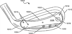
Figure 10 A to 10C has shown the rearview according to the glof club head 1000 of at least some embodiment of the present invention.The glof club head 1000 of this example arrangement comprises is arranged to the rear cavity relative with striking surface 1002.The bridge members 1004 with front surface 1006 and rear surface 1008 is extended across rear cavity 1002, at the heel 1010 of connecting-rod cap 1000 from the heel 1010 of bar head 1000 to toe 1012 and alternatively and toe 1012 or otherwise the direction of extending to toe 1012 from the heel 1010 of bar head 1000.Bridge members 1004 also can be extended and/or be connected to each other positions on glof club head 1000 across rear cavity 1002, for example, and as at United States Patent (USP) the 6th, shown in 450,897.Bridge members 1004 can be configured to various shapes, as above in conjunction with as described in Fig. 1-5A, and it can be in any desired way and the remainder that forms and/or be connected to golf club head structure 1000 together with the remainder of golf club head structure 1000, comprise the variety of way described in above combination Fig. 1-5A.
If needed, bridge members 1004 can form in single foundry goods together with glof club head 1000, thereby makes bridge members 1004 and glof club head 1000 form entirety.As possibility, if needed, bridge members 1004 can be used such as rivet of mechanical connection thing or screw 1014, bonding agent or adhesive, fusion technique (such as welding, soft soldering or brazing) etc. to be connected to toe 1012 and the heel 1010 (or other parts) of bar header structure 1000.Certainly, those skilled in the art will appreciate that bridge members 1004 can be used still less or extra tie point and/or be connected to toe 1012 and/or heel 1010 by a lot of other interconnection techniques and device, and do not depart from the present invention.
As shown in further in Figure 10 A to 10C, bar header structure 1000 comprises that the feel between bridge members 1004 and the rear end face 1002 that is for example arranged on bar header structure 1000 changes element 1016.Feel changes element 1016 can have various forms, and is connected with the remainder of bar header structure 1000 in any desired way, comprises various forms and mode that above combination Fig. 1-9 pair element 232,234 and/or 632 is described.
According at least some embodiment of the present invention, bridge members 1004 can have one or more balancing weights 1018, these balancing weights are for example connected to bridge members 1004 at each fixed position place shown in Figure 10 A to 10C, for example, be connected to the front surface 1006 of bridge members 1004.As example more specifically, Figure 10 A has shown the balancing weight 1018 that is connected to the front surface 1006 of bridge members 1004 close to the toe 1012 of glof club head 1000.As possibility, balancing weight 1018 can be connected to front surface 1006 close to the heel 1010 (Figure 10 C) of glof club head 1000 in the central authorities of bridge members 1004 (Figure 10 B) or.As other example, if needed, one or more balancing weights 1018 can be connected to each position on the rear surface 1008 of bridge members 1004 and/or be assembled in slit, groove or other jacks of bridge members 1004 interior formation, and do not depart from the present invention.
Certainly, those skilled in the art will appreciate that balancing weight 1018 can be made up of various shapes and/or size, for example rectangle, avette, triangle, trapezoidal, square, oval or other symmetrical or asymmetrical shapes.In the example shown in Figure 10 A to 10C, balancing weight 1018 is illustrated as rectangle or square. weight chip conventionally.Balancing weight 1018 can be made up of the material of any expectation, comprises one or more materials of the group of selecting free stainless steel, carbon steel, titanium, aluminium, tungsten, graphite, lead, polymer, plastics or compound or combinations thereof.In addition,, if needed, balancing weight 1018 can optionally be removed and/or can exchange with the multiple optional balancing weight with different size, shape and/or quality compared with balancing weight 1018 from bar header structure 1000.Such parts can be used for further controlling and/or changing center of gravity, counterbalance feature and/or the hand feel characteristic of glof club head 1000.
Balancing weight 1018 can use rivet, hold-down screw or stop pin 1020 to be connected to front surface 1006 or the rear surface 1008 of bridge members 1004.Certainly, those skilled in the art will recognize that, balancing weight 1018 can be in any desired way connected to and/or locks onto in the position in bridge members 1004 and do not depart from the present invention, the various modes that comprise utilizing attaching parts such as lock screw, clamp, clip, clasp etc. and/or use adhesive or fusion technique.Those skilled in the art it will also be appreciated that more than one balancing weight 1018 can be connected to bridge members 1004 at each diverse location, and do not depart from the present invention.
With with the identical mode of conventionally describing in conjunction with Fig. 1-9 above, according to the example shown in this, can such as, by using bridge members 1004 and/or balancing weight 1018 (and/or the miscellaneous part of bar head 1000, feel change element 1016, wall etc.) to control the distribution of weight of glof club head 1000 and/or the position of its mass centre.As example more specifically, bridge members 1004 and/or balancing weight 1018 can be used for increasing the back of glof club head 1000 with respect to the weight of its striking surface.Weight has changed the center of gravity of glof club head 1000 towards the increase at the rear portion of glof club head 1000.Swerve the weight by more lowland and the rear portion towards glof club head 1000, golf driving will trend towards having the pole face angle of increase in the time clashing into golf.By swerving the weight higher and towards the rear portion of glof club head 1000, golf driving will be provided the control of the increase to golf driving by trending towards having the pole face angle and/or the user that reduce in the time clashing into golf clubs.
Referring to figures 10A to 10C, moveable counter weight piece 1018 is to allow the position of centre of gravity of user, designer and/or club assembler adjustment and control lever head 1000.By balancing weight 1018 is moved to the diverse location as shown in Figure 10 A to 10C, can change and control the center of gravity of glof club head 1000 with respect to the position of striking surface.Particularly, can help to improve with respect to the position of centre of gravity of striking surface Mobile golf bar head 1000 and have towards the left side of alley or the golfer's of the tendency of right side putt ball flight and/or help to stop golfer ball to be hit too far to left side or the right side of alley.For example, Figure 10 A has shown the balancing weight 1018 of arranging towards the toe 1012 of glof club head 1000.This layout often makes golf move (for right-handed golfer) towards the right side of alley, because during swinging, the toe 1012 of bar head 1000 will trend towards lagging behind a little, thereby make rod head end face in the time clashing into golf, open wide a little (with compared with identical the swinging that there is no balancing weight 1018 of this position).Therefore,, in the position of Figure 10 A, bar head 1000 will have miss or Draw oblique line and/or may have the golfer of left hook or right hook tendency useful to helping.In Figure 10 C, balancing weight 1018 is placed towards the heel 1010 of glof club head 1000, this often makes golf move (for right-handed golfer) towards the left side of alley, because during swinging, the toe 1012 of bar head will trend towards a little before heel, thereby make rod head end face closed (with compared with identical the swinging that there is no balancing weight 1018 of this position) a little in the time clashing into golf.Therefore,, in the position of Figure 10 C, bar head 1000 will have left hook or right hook oblique line and/or may have the golfer of Draw or miss tendency useful to helping.In Figure 10 B, balancing weight 1018 is connected to front surface 1006 near the central authorities of bridge members 1004, and this trends towards producing the straight line guiding balance of golf or the batting of non-deflection (supposing to produce square contact during swinging) along towards alley central authorities.
Figure 11 A to 11C has shown another embodiment comprising as the golf clubs 1100 of the weighted 1102 of the part of bar header structure 1100.In this example arrangement 1100, weighted 1102 has elliptical shape.The balancing weight 1102 of this elliptical shape can be arranged in each the fixing position in bridge members 1104, compares as shown in its position in Figure 11 A to 11C as passed through.In addition, the balancing weight 1102 of elliptical shape is rotatable, further to change and to control the center of gravity of glof club head 1100 with respect to the position of striking surface (for example,, in its position of second direction control, as in the vertical direction).As discussed above, the position of centre of gravity of the glof club head in conventionally vertical direction affects golf driving and whether presents the track of height, arc or lower, more flat track.Therefore, with the abutment of bridge members 1104 on the balancing weight 1102 of rotation and location elliptical shape by the center of gravity of the glof club head 1100 that trends towards raising a little.As the above mentioned, the center of gravity of rising glof club head 1100 helps golfer with lower and controlled track promotion golf more.Alternatively, with the abutment of bridge members 1104 under the balancing weight 1102 of rotation and location elliptical shape will trend towards reducing the center of gravity of glof club head 1100, thereby allow better golfer to promote golf with extra pole face angle.
As shown in further in Figure 11 A to 11C, bar header structure 1100 comprises that the feel between bridge members 1104 and the rear end face 1108 that is for example arranged on bar header structure 1100 changes element 1106.Feel changes element 1106 and can adopt various forms and/or be connected with the remainder of bar header structure 1100 in any desired way, comprises various forms and mode that above combination Fig. 1-9 pair element 232,234 and/or 632 is described.
The balancing weight 1102 of elliptical shape can be in any desired way connected to front surface 1110 and/or the rear surface 1112 of bridge members 1104, for example, use hold-down screw and stop pin 1114, lock screw, clamp, clasp, clip or other mechanical connection things.Certainly, it will be understood by those skilled in the art that balancing weight 1102 can be connected to bar head 1100 by various different modes, and it can have various difformities, composition, structure etc., and not depart from the present invention.In addition,, if needed, for example oval ground or the multiple weighted 1102 that are shaped in other mode can be connected to bar head 1100, and do not depart from the present invention.
Figure 12 A to 12D has shown the another embodiment according to bar header structure 1200 of the present invention.As shown in Figure 12 A to 12D, glof club head 1200 comprises rear wall 1202, and defines and be arranged to the rear cavity relative with striking surface.The bridge members 1204 with front surface 1206 and rear surface 1208 is in the heel 1210 of bar head 1200 and the direction of toe 1212 and/or be connected to that in the direction between heel 1210 and the toe 1212 of bar head 1200, to extend across rear cavity (be also possible although connect in the bridge members 1204 of other position, as mentioned above and shown in, for example, at United States Patent (USP) the 6th, in 450,897).As above, in conjunction with as described in Fig. 1-5A, bridge members 1204 can be by various shapes, various width and/or thickness and/or with consistent with its length or inconsistent width and/or thickness manufacture.Bridge members 1204 also can form and/or be in any desired way connected to the remainder of golf club head structure 1200 together with the remainder of golf club head structure 1200, comprises the mode described in above combination Fig. 1-11C.
If needed, at least some embodiment of the present invention, bridge members 1204 can form in single foundry goods together with glof club head 1200, thereby produces and the integrant bridge members 1204 of glof club head 1200.As possibility, bridge members 1204 can be used hold-down screw 1214 to be connected to toe 1212 and/or heel 1210 (or other parts of bar header structure 1200).Certainly, those skilled in the art will recognize that, bridge members 1204 can be used tie point still less or extra and/or be connected to toe 1212 and/or heel 1210 (or other parts of bar header structure 1200) by a lot of other jockeys or system, and do not depart from the present invention, as conventionally described above.
As shown in Figure 12 A to 12C is further, bar header structure 1200 comprises that the feel between bridge members 1204 and the rear end face 1202 that is for example arranged on bar header structure 1200 changes element 1216.Feel changes element 1216 and can adopt various forms and/or be connected with the remainder of bar header structure 1200 in any desired way, comprises various forms and mode that above combination Fig. 1-9 pair element 232,234 and/or 632 is described.
In structure 1200 shown here, bridge members 1204 is included in the track 1218 forming on its front surface 1206.In Figure 12 D, shown an example for the structure of track 1218, it shows that track 1218 comprises the groove 1220 of the first surface 1222 for engaging balancing weight 1224.The second surface 1226 of balancing weight 1224 can slide along the outside of track 1218, allows golfer or club assembler for example with hold-down screw 1228, balancing weight 1224 to be locked onto in position selected and that expect.If needed, hold-down screw 1228 can be assembled in the one or more grooves or opening that are arranged in groove 1220, to assist in ensuring that balancing weight 1224 remains locked in suitable position.Use the golfer of the glof club head 1200 of Figure 12 A to 12D optionally to locate balancing weight 1224 in each position along track 1218.For example, as shown in Figure 12 A, balancing weight 1224 can be arranged in close on the track 1218 of the position of the toe 1212 of glof club head 1200 (for example, as the help to the golfer who trends towards left hook, more easily to provide right hook oblique line towards central authorities' batting of alley and/or as bar head 1200).As possibility, as shown at Figure 12 B, balancing weight 1224 can be positioned near the central authorities of bridge members 1204, for example, and for trending towards attacking directly ball and/or the golfer of ball flight tendency that determine or deflection clearly not.As another possibility, as shown at Figure 12 C, balancing weight 1224 also can be located at close on the track 1218 of the position of the heel 1210 of glof club head 1200 (for example, as the help to the golfer who trends towards miss, bat and/or provide miss oblique line to bar head 1200 with the easier central authorities towards alley).By along track 1218 self-balanced upper rotary 1224, the center of gravity that golfer optionally changes bar head 1200 is in a first direction with respect to the position of striking surface, for example, to meet golfer's the specific style of playing and performance, thereby help as one man to revise undesirable ball flight etc.Therefore, golfer can change by reconfigure the center of gravity of bar head 1200 with respect to the striking surface of bar head the common flight path of golf.
Figure 13 A to 13C has shown another example club head structure 1300 according to some embodiments of the present invention.As shown at Figure 13 A, comprise heel 1302, toe 1304 and be provided for the striking surface of the contact area that engages golf according to the glof club head 1300 of this example arrangement.Glof club head 1300 also comprises rear wall 1306, and defines the rear cavity relative with striking surface.Bridge members 1308 is extended across rear cavity in the direction between toe 1304 and heel 1302.Glof club head 1300 further comprises and the integrant weight configuration component 1310 of bridge members 1308.Weight configuration component 1310 comprises track or groove 1312 and is connected to movably the balancing weight 1314 of track 1312.Track 1312 can extend to its rear surface 1318 from the front surface of bridge members 1,308 1316, or it can only partly extend through the thickness of bridge members 1308.Balancing weight 1314 can for example move, with in a first direction with respect to striking surface (along track 1312, in the direction of common level and/or along the direction of track 1312) change the position of centre of gravity of glof club head 1300, and it can locked (for example,, by screw 1320, stop pin or other retaining elements) in position so that it is remained on along the desired locations of track 1312.
There is elliptical shape at the balancing weight 1314 shown in the example of Figure 13 A to 13C.The balancing weight 1314 of elliptical shape can for example use the combination (or the fixed mechanism of other expectations or structure) of packing ring and hold-down screw 1320 be positioned in each position in bridge members 1308 and keep in position.As described in conjunction with Figure 11 A to 11C above, balancing weight 1314 is also rotatable, further to change the position of centre of gravity of glof club head 1300 with respect to striking surface in second direction, for example, conventionally to change position of centre of gravity in vertical direction.
As described about various other example arrangement, the position of centre of gravity of glof club head 1300 affects golf driving and whether presents the track of height, arc or low, more flat track.Therefore, with the abutment of bridge members 1308 on raise a little center of gravity of glof club head 1300 of the balancing weight 1314 of rotation or location elliptical shape.The center of gravity of rising glof club head 1300 allows golfer with lower and more that controlled track promotes golf conventionally.Alternatively, with the abutment of bridge members 1308 under the center of gravity of balancing weight 1314 slight reduction glof club heads 1300 of rotation and location elliptical shape, thereby conventionally allow golfer for example with extra pole face angle, golf to be promoted to get Geng Gao.By the balancing weight 1314 with two dimension or three-dimensional movement and ellipse of revolution shape shape, golfer or club assembler have on demand the great flexibility with respect to the position of centre of gravity of striking surface backstay head 1300, for example, so that club deflection and (for example produce specific shot shapes, miss, Draw etc.), to help to correct the ball flight path problem that occurs due to some mistake that swings etc.
Comparison reveals by Figure 13 A to 13C the example more specifically of weight and centre of gravity adjustment.As shown at Figure 13 A, the balancing weight 1314 of elliptical shape is positioned near the bridge members 1308 toe 1304 of glof club head 1300.In addition, the balancing weight 1314 of elliptical shape rotates to the position on the abutment of balancing weight 1314 and bridge members 1308 and/or on the abutment between bar head 1300 and golf, as in Figure 13 A, partly the outward appearance of the oval part of the balancing weight 1314 at raised position place on bridge members 1308 is represented.This of the balancing weight 1314 of elliptical shape is arranged and will be trended towards backward and raise and the center of gravity of Mobile golf bar head 1300 towards the toe 1304 of glof club head 1300.The golf driving with this specific golf club head configuration trend towards for right-handed golfer towards the right side of alley with lower and more controlled track promote golf.
As another example, Figure 13 B shows near the balancing weight 1314 of the elliptical shape of the central authorities of the bridge members 1308 that is positioned at glof club head 1300.And, the balancing weight 1314 of elliptical shape rotate to the abutment of bridge members 1308 on and/or position on the abutment of bar head 1300 and golf, as represented in appeared at the raised position of the oval part by balancing weight 1314 on bridge members 1308 in Figure 13 B.This layout of the balancing weight 1314 of elliptical shape will trend towards the center of gravity of glof club head 1300 that raises, and it is moved backwards.The golf driving with this specific golf club head configuration will trend towards towards the central authorities of alley with lower and controlled track and/or do not deflect into the right side of alley or left side and promote golf in ball flight more.
As further example, Figure 13 C has shown the balancing weight 1314 of the elliptical shape near the bridge members 1308 heel 1302 that is located at glof club head 1300.In addition, in example shown here, the balancing weight 1314 of elliptical shape rotate under the abutment of balancing weight 1314 and bridge members 1308 and/or the abutment of bar head 1300 and golf under position, as represented in the outward appearance of the oval part of the balancing weight 1314 under bridge members 1308 in Figure 13 C.This of the balancing weight 1314 of elliptical shape is arranged and is reduced backward and the center of gravity of Mobile golf bar head 1300 towards the heel 1302 of glof club head 1300 trending towards.The golf driving with this specific golf club head configuration promotes golf (for example, help correct miss, Draw deflection to club etc. be provided) towards alley left side with higher track for right-handed golfer by trending towards.
Certainly,, if needed, the balancing weight 1314 of elliptical shape can be had the balancing weight for subsequent use of difformity and/or different quality to be replaced, the degree being reconfigured to increase or to reduce the center of gravity of bar head 1300.Various shapes, for example rectangle, avette, triangle, trapezoidal, square and other symmetrical or asymmetrical shapes can be used for weighted 1314.The balancing weight 1314 of elliptical shape or the weighted of other expectations can be made up of different materials, for example lead, stainless steel, carbon steel, titanium, aluminium, tungsten, graphite, polymer, plastics or compound or its combination.Balancing weight also can be placed along the front surface of bridge members 1,308 1316, and does not depart from the present invention.Can use weighted 1314, any combination along the weight location of track 1312 and/or the rotation of oval balancing weight 1314 location, and not depart from the present invention.
Figure 14 and the 15 other examples of showing according to the bar header structure with weighted 1402 and 1,502 1400 and 1500 of embodiments of the invention.In these example arrangement, as above, previously described, multiple balancing weights 1402 and 1502 are with the bridge members 1404 and 1504 that is connected of configuration, for example, to change and to control the position of centre of gravity of glof club head 1400 and 1500.For example, as shown in Figure 14, multiple balancing weights 1402 can for example be connected in the mode of describing in conjunction with Figure 12 A to 13C the multiple tracks or the groove 1406 that are arranged in single bridge members 1404 above movably.In the time there is multiple track, they can be relative to each other for example, in the layout of any expectation (, substantially conllinear, stacking, overlapping, etc.).Alternatively, if needed, balancing weight 1402 can be positioned at the fixed position in bridge members, for example, and as described to 11C in conjunction with Figure 10 A above.As another selection, if needed, one or more balancing weights can be positioned at the fixed position in bridge members, and one or more other balancing weight is connected to track or other variable weight configuration components movably.As another example, as shown in Figure 15, multiple balancing weights 1502 can be connected to the single track 1506 in bridge members 1504 movably, extra weight be increased to the back of bar head 1500 and allow people further to change and control the position of centre of gravity of glof club head 1500.One or more balancing weights 1500 can be shaped as shown in Figure 15 ovally, or are shaped in some other modes, and do not depart from the present invention.
For example, although the bar head that the example shown in Fig. 9-15 shows Fig. 6-9 shown type conventionally (, there is the wall member 630 on bridge members of being arranged on 624 and be arranged in the open region under bridge members 624 and visible feel change element 632), but it will be understood by those skilled in the art that, of the present invention one or more identical parts shown in Fig. 9-15 can be in the bar head of Fig. 1-5A shown type (for example, there is wall member under bridge members of being arranged on 224 230 and be arranged in the open region of bridge members 224 and visible feel changes element 232 and/or 234) and/or (for example do not comprising additional wall member 230 and 630, and feel changes member, in the time that it exists, can be on bridge members and under visible) bar head in put into practice.
Can be merged into according to the glof club head of embodiments of the invention a set of, for example, a set of iron and/or hybrid type golf clubs.For example, aspect of the present invention can be used for providing the loop bar of the golf iron of the quantity with increase, for example, mixed type club, No. 1 midiron, No. zero iron, iron, No. two irons, No. three irons, No. four irons, No. five irons, No. six irons, No. seven irons, No. eight irons, No. nine irons, No. ten irons, pitching wedge, highly throw two or more in wedge, relaying wedge, sand pit wedge etc.Use the present invention, golfer, club designer and/or club assembler can change the position of centre of gravity of each golf clubs, to meet player's unique needs, skill or the style of playing.To the each club in loop bar, bridge members (and/or the miscellaneous part of bar head, such as wall member, feel change member, weighted etc.) can little by little change, to change the center of gravity with respect to a club member of other clubs in loop bar, thereby make center of gravity be suitable for being better customized to alternatively the use for the specific club of specific golfers.
III. conclusion
With reference to the combination of various example arrangement, parts, element and example arrangement, parts, element, the present invention is described above and in the accompanying drawings.But the object that the disclosure provides is to provide the embodiment about various features of the present invention and concept, instead of limit object of the present invention.Those skilled in the art will appreciate that and can above-described embodiment much be changed and be revised, and do not depart from scope of the present invention as defined by the appended claims.For example, various features and concept described in above combination Fig. 1-15 can be used individually and/or with any combination or sub-portfolio, and do not depart from the present invention.