CN1013852B - Double drive bicycle - Google Patents
Double drive bicycleInfo
- Publication number
- CN1013852B CN1013852B CN88101786A CN88101786A CN1013852B CN 1013852 B CN1013852 B CN 1013852B CN 88101786 A CN88101786 A CN 88101786A CN 88101786 A CN88101786 A CN 88101786A CN 1013852 B CN1013852 B CN 1013852B
- Authority
- CN
- China
- Prior art keywords
- gear
- handle
- bicycle
- mentioned
- wheel
- Prior art date
- Legal status (The legal status is an assumption and is not a legal conclusion. Google has not performed a legal analysis and makes no representation as to the accuracy of the status listed.)
- Expired
Links
Images

Classifications
-
- B—PERFORMING OPERATIONS; TRANSPORTING
- B62—LAND VEHICLES FOR TRAVELLING OTHERWISE THAN ON RAILS
- B62M—RIDER PROPULSION OF WHEELED VEHICLES OR SLEDGES; POWERED PROPULSION OF SLEDGES OR SINGLE-TRACK CYCLES; TRANSMISSIONS SPECIALLY ADAPTED FOR SUCH VEHICLES
- B62M1/00—Rider propulsion of wheeled vehicles
- B62M1/12—Rider propulsion of wheeled vehicles operated by both hand and foot power
-
- B—PERFORMING OPERATIONS; TRANSPORTING
- B62—LAND VEHICLES FOR TRAVELLING OTHERWISE THAN ON RAILS
- B62M—RIDER PROPULSION OF WHEELED VEHICLES OR SLEDGES; POWERED PROPULSION OF SLEDGES OR SINGLE-TRACK CYCLES; TRANSMISSIONS SPECIALLY ADAPTED FOR SUCH VEHICLES
- B62M23/00—Transmissions characterised by use of other elements; Other transmissions
Abstract
The invention has an upper support attached to the upper of the frame. A hand wheel is mounted on the upper support. Handles are provided which drive the hand wheel and are manually actuatable by the driver. Gears are mounted on the upper support. A loop connects the hand wheel and the gears, whereby rotation of the hand wheel causes rotation of the gears. Locking devices are provided to detachably lock the hand wheel to the upper support so that the handle and the loop remain in fixed position. A gear is axially mounted on the front wheel. A chain connects the gear to the gears whereby the gears are rotatable with the handle.
Description
The present invention relates to a kind of bicycle, more particularly relate to a kind ofly activate by stretcher and the motion of control trailing wheel or each trailing wheel and have a kind of bicycle of handle of the raising that is used to drive front-wheel by steerman.
The disclosed in the prior art action of attempting to utilize hand drive bicycle front-wheel as bicycle.Of the prior art each all have one or more shortcomings for example.These shortcomings comprise: clumsy, power-handling capability passing through the footboard drives trailing wheel with the hand-drive front-wheel or with pin, lacks the driving of carrying out hand and pin simultaneously to the steerman capabilities limits without male offspring, perhaps lacks with hand and carries out the selection that friction speed drives.In addition, existing bicycle is not easy to change into the hand-drive bicycle of those inventions.
The invention provides a kind of bicycle that carries out the hand-drive front-wheel independently that has, as a kind of (two-wheel) bicycle.The present invention is by providing a kind of manual drives, and the multiple speed f-w-d has improved existing bicycle, and this f-w-d and back-wheel drive are separate and can dally.Other advantage of the present invention will come into plain view by being described below in conjunction with accompanying drawing with claim.
The present invention includes a kind of crossbeam that has, a front-wheel, one or two trailing wheel and in order to the bicycle of the stretcher that drives trailing wheel such as two-wheel or tricycle, wherein: (1) wheel with a pair of handle is placed in last the place ahead of crossbeam in order to the replacement handlebar; The unidirectional rotation gear cluster of (2) variable-ratios is installed in the top of crossbeam; (3) driven wheels are installed in the axial of front-wheel.For no reason an endless belt; As a belt or chain this wheel is connected with the variable-ratio gear cluster, chain is connected to a gear through selecting of change-gear set on the f-w-d gear by a derailleur.The hand that the device that is used to control derailleur is installed in steerman is approaching position easily.
Most preferred embodiment of the present invention is that various bicycles is characterized in that they have following element.A upper support device is installed in the front upper place of crossbeam.A handwheel is installed on this upper support device.Be provided with the handle apparatus of a driving handwheel and by steerman manually to activate.A kind of gear mechanism is installed on the upper support device, is provided with an endless belt in order to connect handwheel and gear mechanism, causes the rotation of gear mechanism according to this by the rotation of handwheel.Being provided with latching device is used for handwheel releasably is locked on the upper support device so that make handle apparatus and endless belt remain on fixing position.A gear is installed in the axial of front-wheel.A chain is connected this gear on the gear mechanism, makes gear and handle apparatus co-rotation according to this.
The requirement that is used for existing two-wheeled cycle or tricycle are transformed into bicycle of the present invention mainly comprises: replace another trailing wheel and the upper handle steering handwheel is installed in preferably adjustable special-purpose a support for the requirement of front-wheel and go up so that adapt to the requirement of steerman.The support that is installed on the bicycle crossbeam also can be used as the position that front-wheel and trailing wheel are distinguished conversion and control.Brake controller preferably is installed on the handle of stick control handwheel.A specific embodiment of the present invention is described below, and should be pointed out that many change types consider within the scope of the invention.The a plurality of gears that change by derailleur can be any amount of like this, for example 3 to 12.When being used for tricycle, its rear drive is the centre at two wheels.Change-speed box can perhaps be decided according to the designing requirement of bicycle according to conveniently being arranged on the various positions of steerman.When needs, can replace chain with belt.And the present invention both can be by bicycle the motion backward of stretcher brake, as adopting the device of falling the wheel brake, also can utilize hand-guided drg, for example contracting brake.
Can be locked on the optional fixed position as a kind of handle that freely is chosen in the f-w-d system.The hand brake that is connecting brake controller preferably is located on the axle of a ball bearing, when with box lunch front-wheel being applied 360 ° of powered rotation, rope stopper can not snarled.The trailing wheel of the conventional bicycle of band chain wheel can and will usually be configured on the standard front fork cover joint of modern bicycle as the f-w-d system.This sprocket wheel is the free gear pattern, and steerman can break away from its both hands in 360 ° revolution like this, and does not need to change its handle or hold drg with finger.
The present invention also can adopt two kinds of different systems of the change gear ratio that is used for bicycle, i.e. for example three-speed gear hub and derailleur of variable gear hub.In the variable gear hub, the conversion of gear is that utilization is by being installed in handle and supporting a gear Quality Initiative of going up by a lever-operated control cord actuating and operate.This chain is along the sun wheel of two compound planet gears of principal axis transformation of gear hub.Preferably adopt the gear transmission system described in concrete giving an example, this variable gear hub also can be used for the position of f-w-d system.
Another feature of the present invention is that this big gear wheel can be two chain-wheel bicycle cranks of standard.This endless belt or chain are reached on the gear cluster by hinge wheel.Minor sprocket be used for gear teeth locking minor sprocket on screw be connected so that handle is remained on a selected position.
Another feature of the present invention is, when the bicycle crossbeam of a routine is the cover that adopts detouchable handlebar and shank and be used to install shank in the past when saving, can be used for fixing upper support.
Preferably the handle in handle arm is installed on the ball bearing of main shaft, so that brake controller can be installed on the handle.Ball bearing of main shaft can make rope stopper float, so this rope stopper just can not be snarled and the control of braking lever also makes the finger of steerman approaching so that at any time brake easily, and this compared with prior art is significantly improved at secure context.
Handle can be located selectively, so that make its left side, the handle of right-hand operated aligns in a straight line mutually, or away from or at midway location.By the position selected after, steerman just can be complied with its arm and be practised aspect different.For good stability, two handles preferably are positioned on the straight line as shown in Figure 4.
Drg and change-speed box can be installed in the grip near handwheel, so that steerman is approaching easily.Variable speed operation is by stopping to travel forward of handle, pick-off gear turns round backward to handle derailleur, drives then to realize.
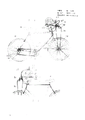
Fig. 1 is a right side view of one embodiment of the present of invention;
Fig. 2 is the left upper portion front elevation of embodiment shown in Figure 1;
Fig. 3 is the most front elevation in top after lid is dismantled embodiment illustrated in fig. 1;
Fig. 4 is the slightly three-dimensional partial view of a upper front after lid is dismantled embodiment illustrated in fig. 1;
Fig. 5 is a previous section right side enlarged drawing embodiment illustrated in fig. 1;
Fig. 6 is the right side view of the front upper of an alternative embodiment of the invention;
Fig. 7 is the most view in fwd right side of embodiment shown in Figure 6;
Fig. 8 is the most view in left side, back of embodiment shown in Figure 6.
Referring to Fig. 1 to Fig. 5, bicycle 10 has a crossbeam 11 and a front-wheel 12 and a trailing wheel 13 is installed on it.Crossbeam 11 has a front fork 11a and a cover joint 11b, and handlebar just inserts in this cover joint in the bicycle of routine.By wheel hub 12a that front fork 11a is mounted thereto and have a sprocket wheel 12b on front-wheel 12.Trailing wheel 13 has a wheel hub 13a and sprocket wheel 13b.Vehicle seat 18 is installed on the crossbeam 11.Be attached to the stretcher 14 of having on the crossbeam 11 together with gear mechanism 15.A rear chain 16 is connected with gear mechanism 15 with stretcher 14 by rear derailer 17.
In the front of crossbeam 11 are adjustable crossbeam extensions 20, comprise that a pair of stay bearing plate 19a of upper support 19 and 19b are attached on this extension 20.Support 19 and can turn round adjustment around pivot 19d, until obtain desired position, pass through among the screw insertion hole 19c then, this hole aligns mutually with a upper hole of extension 20, is fixed on this position.
Have a wheel hub 21 on the top of supporting 19, which is provided with handle 22a, this handle comprises that upright arm 22 and handle 23 and this handle 22a are to be connected on the axle of big gear wheel 24.Big gear wheel 24 has some spokes 25 and drives a chain 29, this chain is to be connected on the gear cluster 30 that comprises the gear of amplifying successively, this gear cluster selectively is connected again on the derailleur 32, and sprocket wheel 12b is mounted on the wheel hub 12a of front-wheel.
Being used for cable wire 34 to the manual mode controller 33 of derailleur 32 can allow the steerman of bicycle that chain 31 is transformed into a selected gear in the gear of the changed size of gear cluster 30.Move on handle 23 with hand like this and just can reach a selected speed to drive front-wheel.The brake controller 35 that is installed on the handle 23 connects cable wire 28 on the front-wheel brake.The bicycle operated trailing wheel of steerman is to carry out in the mode of routine by being installed in brake controller 36 on another handle 23 and the rear-wheel transmission 26 that is positioned on the upper support.Lid 37 is to avoid the mechanics of wheel 24 and damaging of the chain 29 that links to each other in order to the protection user with 38 setting.
Referring to Fig. 6 to Fig. 8, show a upper support embodiment different among the figure with handwheel, and crossbeam, vehicle seat and wheel are all same as shown in Figure 1.
Upper support 119 is to sentence pivotal joint on adjustable crossbeam extension 120 at 119b, and utilizes a bolt to be fixed to the top of extension 120 by a selected hole 119a with the elevation angle of a requirement.The part of support 119 has one and is connected in a wheel hub 121 of pulling on 138.An axle and a bearing that stretches out by wheel hub 121 is connected on arm 122 and the handle 123, and this handle is used to drive big gear wheel 124 chains 129 and moves thereon.Chain 129 activates 130 work of said gear group.This gear cluster 130 has the gear of selecting by derailleur 132, so that chain 131 is connected on the f-w-d gear 12a.
This big gear wheel 124 has one with tooth 142a and the staggered plate 142 of groove 141a and a hole 141.Bolt 140 is applicable to and removably stretches out by hole 141 so that match with a selected groove 141a.After the big gear wheel 124 of such cooperation and handle are locked, for example be locked at the position shown in Fig. 7.At such locked position, handle 123 plays the normal fixedly effect of handlebar, and f-w-d is in dead status.
Manipulation by arm 122 and 123 pairs of big gear wheels of handle causes chain 129 to drive said gear group 130.The work that is used for the derailleur 132 of f-w-d chain 131 by change is to utilize the controller 134a that is connected derailleur 132 to realize by cable wire 134.The brake controller 135 and 136 that is used for front-wheel and trailing wheel all is mounted in the handle 123 that separates.
Claims (30)
1, a kind of bicycle, it includes:
(a) upper support device is arranged on last the place ahead of crossbeam;
(b) handwheel is installed on the upper support device;
(c) a kind of that be used to drive handwheel and be handle apparatus by the steerman manual activation;
(e) endless belt that is connected on handwheel and the wheel word rotates the rotation that handwheel causes wheel word according to this;
(g) gear is installed in the axial of front-wheel;
(h) one is connected to chain on the said gear device with this gear; This gear is rotated with the rotation of handle device;
It is characterized in that it also has:
(d) a kind of wheel word that is installed on the upper support device;
(f) be used for handwheel removably is locked at a kind of latching device on the upper support device, so that handle apparatus and endless belt are remained on the fixing position.
2, bicycle as claimed in claim 1 is characterized in that, described latching device can be locked at handwheel on many positions on the upper support device selectively.
3, bicycle as claimed in claim 2, it is characterized in that, also have a gear shift mechanism that is installed on the upper support, this gear shift mechanism comprises a derailleur, and wherein this chain is connected to this derailleur on said gear device and the said gear.
4, a kind of bicycle that has the cover joint that is used to install handlebar, it has:
(a) a kind of upper support device that is installed on the cover joint;
(b) gear is installed on the upper support device;
(c) a kind of handle apparatus that is used to rotate this gear on the gear that is installed in, this handle apparatus comprises first and second handles and relative first and second handle arm, wherein first and second handles are to be installed in rotation on this handle arm, can make handle be independent of the rotation of this gear thus;
(e) several gears are installed on upper support, wherein these gears all are different big or small;
(f) speed-change gear is installed in the front of several gears on the upper support, and this gear change mechanism comprises a pick-off gear transmission device;
(g) one first endless band is connecting this gear and these several gears, successively the rotation of handle apparatus is caused the rotation of several gears;
(h) front-wheel has one and axially is installed in a gear on the wheel hub at it;
(i) one second for no reason endless belt connecting the gear that this is axially installed, gear change mechanism and above-mentioned several gears;
It is characterized in that it also has:
(d) on the outside face that finger actuated brake lever and brake cable are installed in handle, the cable wire that wherein is installed on the handle is protruding to provide handle to carry out 360 ° revolution by handle, avoids cable wire to be wound with this.
5, bicycle as claimed in claim 4 is characterized in that, it also has an adjustable crossbeam extension to be applicable to can pivotal mounting the upper support device, and wherein this adjustable crossbeam extension is mounted on the cover joint.
6, bicycle as claimed in claim 4 is characterized in that, it comprises that also a change-speed box that is installed on the above-mentioned handle is used for the conversion of above-mentioned several gears.
7, bicycle as claimed in claim 5 is characterized in that, the installation of this pivot is in order to provide several fixed positions.
8, bicycle as claimed in claim 4 is characterized in that, comprises that also a kind of latching device is used for removable the turning up the soil of said gear is locked on this upper support device so that the fixed installation of handlebar to be provided.
9, bicycle as claimed in claim 4 is characterized in that described f-w-d device and the back-wheel drive device that is installed on the bicycle is separate.
10, bicycle as claimed in claim 4 is characterized in that, also comprises at least one trailing wheel.
11, bicycle as claimed in claim 4 is characterized in that, described two handles are common outwardly directed so that form the handle bar structure of a routine.
12, a kind of bicycle, it has:
(a) position, front upper place of supporting the bicycle crossbeam be suitable for being connected common installation handlebar on the whole;
(b) big gear wheel that has handle apparatus thereon is installed in and is used on the upper support rotating;
(c) a kind of device of an axle mounting in above-mentioned support that is used for said gear;
(d) a kind of device that is used to install above-mentioned several gears;
(e) a kind of for the device of the latching device that above-mentioned handle apparatus uses is installed;
It is characterized in that it also has:
(f) a kind of latching device is installed in the device that is used to install latching device, and this latching device has a screw, and this screw is suitable for releasably pinning the tooth of big gear wheel to limit the motion of this big gear wheel;
(g) except having f-w-d, also have back-wheel drive.
13, bicycle as claimed in claim 12, it is characterized in that, it also comprises axle, big gear wheel and a handle apparatus, wherein this is mounted in the device that is used for installation shaft, wherein big gear wheel is mounted on this axle, and wherein handle apparatus also is mounted on this axle, and this handle apparatus further comprises two rotating handles that stretch out jointly.
14, bicycle as claimed in claim 13 advances, and it is characterized in that, it also comprises the brake equipment that is installed on the handle with finger actuated.
15, bicycle as claimed in claim 12, it is characterized in that, the described device that upper support is installed on the cover joint comprises an adjustable crossbeam extension that is installed on this cover joint, wherein this upper support is to be pivotally mounted on this adjustable crossbeam extension, many fixed positions can be provided thus.
16, bicycle as claimed in claim 15 is characterized in that, the described device that is used for installation shaft be positioned in order to upper support is installed in device on the cover joint above, this cover joint is used for the installation handlebar.
17, bicycle as claimed in claim 16 is characterized in that, the described device that is used to install several gears is the front that is positioned in order to the device of installation shaft.
18, bicycle as claimed in claim 17, it is characterized in that, (ⅰ) described upper support has many holes and (ⅱ) have the hole of matching with many holes at shank, thus can with upper support with a selected elevation angle by a screw is inserted selected hole of above-mentioned many holes and with hole that it matches in fix.
19, bicycle as claimed in claim 18, it is characterized in that, the described device that is used to install latching device is one and is positioned near the hole in order to the device of installation shaft that one distance is wherein arranged between the device of this hole and installation shaft, and this distance approximates the radius value that is installed in the big gear wheel on this.
20, bicycle as claimed in claim 12 is characterized in that, it is included in above-mentioned upper support in order to the device of this derailleur to be installed.
21, bicycle as claimed in claim 20 is characterized in that, it also comprises a kind of for the device of the change-speed box that is used for the rear drive system is installed.
22, a kind of bicycle, it has:
(a) big gear wheel that handle apparatus is installed thereon is installed on position, front upper place of bicycle crossbeam, and this position is normally in order to install the position of handlebar;
(b) gear of several different sizes is installed in the fwd front upper place of big gear wheel, and these several gears are connected on the above-mentioned big gear wheel with one first chain drive-belt;
(c) gear be installed in front-wheel wheel hub axially, this gear of axially installing is to be connected on some gears with different sizes by one second chain drive-belt;
(d) derailleur that is used for this second chain drive-belt is changed the position on the gear of some different sizes, this transmission device is positioned at the front of the big miniature gears of some differences and is installed in above-mentioned front upper part;
It is characterized in that it also comprises:
(e) a kind of latching device that is used for big gear wheel, make thus handle apparatus be fix to form the bicycle handle bar of common usefulness;
(f) except having f-w-d, also have back-wheel drive.
23, bicycle as claimed in claim 22 is characterized in that, described latching device is a releasable screw, and this screw pins this big gear wheel and rotates to prevent big gear wheel.
24, bicycle as claimed in claim 23 is characterized in that, described latching device is locked at big gear wheel on many positions in order to be provided as, and can make handle apparatus thus is orientable with respect to steerman.
25, bicycle as claimed in claim 24 is characterized in that, this handle apparatus comprises two handle arm of stretching out from the both sides, opposite of big gear wheel, has two handles that are installed in rotation on the handle arm on this handle arm.
26, bicycle as claimed in claim 25, it is characterized in that, it also comprises a kind of finger actuated brake lever that has brake cable on each handle that is installed in, and wherein this brake cable makes this brake lever and the brake cable that matches can not snarl by protruding on this handle thus.
27, bicycle as claimed in claim 26 is characterized in that, it comprises that also a upper support is installed in front upper part, and this upper support is installed with above-mentioned big gear wheel, the gear and the derailleur of some different sizes.
28, a kind of bicycle has one and turns to handle and a front-wheel, and it comprises:
(a) a upper support device is installed in turning to last of bicycle;
(b) handwheel is installed on the upper support;
(c) handle apparatus connects with handwheel, and above-mentioned handle apparatus comprises two handles that stretch out jointly that are used to drive and handle front-wheel steering;
(d) several gears that vary in size are installed in and are used to change gear ratio on the upper support;
(e) one first endless belt is connecting above-mentioned handwheel and the above-mentioned gear that several vary in size; Make the rotation of above-mentioned handwheel cause the rotation of the above-mentioned gear that several vary in size;
(f) gear axially is installed on the above-mentioned handwheel;
(g) one second endless belt is connecting said gear and the above-mentioned gear that several vary in size, and said gear can be rotated with above-mentioned handle apparatus;
It is characterized in that it also comprises:
Finger actuated brake lever and brake cable are installed on the outside face of handle, and the cable wire that wherein is installed on the handle is protruding to provide handle to carry out 360 ° revolution by handle, avoids cable wire to be wound with this;
Above-mentioned handwheel removably is locked at latching device on the above-mentioned upper support device,, thereby provides several fixed positions so that handle apparatus is remained on the latched position.
29, be used for f-w-d is additional to the accessory package device with the bicycle that turns to handle and front-wheel, this device comprises:
(a) upper support device be installed in bicycle turn on be used for supporting a front-wheel drive;
(b) handwheel is installed on the upper support device;
(c) handle apparatus connects with above-mentioned handwheel, and above-mentioned handle apparatus comprises two handles of stretching out jointly that are used to drive and handle front-wheel steering;
(d) several gears that vary in size are installed in and are used to change gear ratio on the upper support;
(e) one first endless belt is connecting above-mentioned handwheel and the above-mentioned gear that several vary in size, and makes the rotation of above-mentioned handwheel cause the rotation of the above-mentioned gear that several vary in size;
(f) gear axially is installed on the above-mentioned handwheel;
(g) one second endless belt is connecting said gear and the above-mentioned gear that several vary in size, and said gear can be rotated with above-mentioned handle apparatus;
It is characterized in that it also comprises:
Finger actuated brake lever and brake cable are installed on the outside face of handle, and the cable wire that wherein is installed on the handle is protruding to provide handle to carry out 360 ° revolution by handle, avoids cable wire to twine with this;
Above-mentioned handwheel removably is locked in latching device on the above-mentioned upper support device, so that handle apparatus is remained on the latched position.
30, device as claimed in claim 29 is characterized in that, above-mentioned latching device can be locked in above-mentioned handwheel on the above-mentioned upper support device on a plurality of positions selectively.
Applications Claiming Priority (2)
| Application Number | Priority Date | Filing Date | Title |
|---|---|---|---|
| US031,745 | 1987-03-30 | ||
| US07/031,745 US4773662A (en) | 1987-03-30 | 1987-03-30 | Double-drive bicycle |
Publications (2)
| Publication Number | Publication Date |
|---|---|
| CN88101786A CN88101786A (en) | 1988-11-09 |
| CN1013852B true CN1013852B (en) | 1991-09-11 |
Family
ID=21861166
Family Applications (1)
| Application Number | Title | Priority Date | Filing Date |
|---|---|---|---|
| CN88101786A Expired CN1013852B (en) | 1987-03-30 | 1988-03-29 | Double drive bicycle |
Country Status (6)
| Country | Link |
|---|---|
| US (1) | US4773662A (en) |
| EP (1) | EP0285115A3 (en) |
| JP (1) | JPS63305087A (en) |
| CN (1) | CN1013852B (en) |
| AU (1) | AU1373188A (en) |
| CA (1) | CA1295852C (en) |
Cited By (2)
| Publication number | Priority date | Publication date | Assignee | Title |
|---|---|---|---|---|
| WO1996030249A1 (en) * | 1995-03-27 | 1996-10-03 | Kaoteh Chai | A pedal cycle having an auxiliary power |
| CN100460268C (en) * | 2006-07-14 | 2009-02-11 | 刘平谦 | Front-drive bicycle |
Families Citing this family (52)
| Publication number | Priority date | Publication date | Assignee | Title |
|---|---|---|---|---|
| CA1273373A (en) * | 1989-07-26 | 1990-08-28 | Ernesto M. Nacar | Hand crank bicycle drive |
| JP2852542B2 (en) * | 1989-10-20 | 1999-02-03 | 本田技研工業株式会社 | Front wheel drive system for motorcycle |
| JPH0813677B2 (en) * | 1990-02-16 | 1996-02-14 | 智行 香西 | Tricycle |
| US5078391A (en) * | 1990-03-22 | 1992-01-07 | Moore Sr David W | Exercising bicycle handlebar arrangement and bicycle equipped therewith |
| ES1013921Y (en) * | 1990-04-20 | 1991-08-01 | Farras Pinos Francesc Xavier | BICYCLE WITH TWO-WHEEL DRIVE. |
| DE4013899A1 (en) * | 1990-04-25 | 1990-12-06 | Eckhard Gruenberg | Front wheel drive bicycle - has manually operated cranks and chain wheel mounted on steering column |
| US5052705A (en) * | 1990-06-15 | 1991-10-01 | Victor Flores | Controlled rotary power transfer apparatus and method for non-driven bicycle wheels and the like |
| US5209507A (en) * | 1990-10-09 | 1993-05-11 | Alberto Domenge | Transmission system for tandem bicycles |
| JP2521283Y2 (en) * | 1991-05-17 | 1996-12-25 | 財団法人自転車産業振興協会 | Upper limb drive bicycle |
| US5385359A (en) * | 1992-04-28 | 1995-01-31 | Ehrbar; James J. | Stabilization device for front wheel drive bicycles |
| US5257553A (en) * | 1992-07-02 | 1993-11-02 | Hsieh Chan Bicycle Co., Ltd. | Auxiliary front wheel driving mechanism for bicycle |
| FR2699884B1 (en) * | 1992-12-31 | 1995-03-17 | Pierre Saliba | AWD bike. |
| US5431614A (en) * | 1993-06-14 | 1995-07-11 | Jeranson; Richard C. | Exercise device and auxiliary power unit for use with bicycle |
| US5328195A (en) * | 1993-07-13 | 1994-07-12 | Graham Sommer | Bicycle having arm assisted drive |
| CN1117676C (en) * | 1993-11-11 | 2003-08-13 | 陈毅永 | Composite driving mechanism and new non motor-driven vehicle |
| US5823554A (en) * | 1994-04-13 | 1998-10-20 | Lau; James C. K. | Folding, pedal-driven vehicle with universal joint transmission system |
| DE29501408U1 (en) * | 1995-01-30 | 1995-09-28 | Disch Roland | Bicycle with hand crank drive |
| DE69610054T2 (en) * | 1995-05-10 | 2001-05-10 | Fabrizio Rigato | BICYCLE WITH ADDITIONAL ARM DRIVE |
| US5816598A (en) * | 1996-03-15 | 1998-10-06 | Dodakian; Wayne S. | Two-wheel drive hand and foot powered bicycle |
| US7328766B2 (en) * | 1996-04-26 | 2008-02-12 | Christini Technologies, Inc. | Two-wheel drive two-wheeled vehicle |
| US6439592B1 (en) | 1996-04-26 | 2002-08-27 | Christini Technologies, Inc. | Two-wheel drive two-wheeled vehicle |
| US6182991B1 (en) | 1996-04-26 | 2001-02-06 | Christini Technologies, Inc. | Two wheel drive bicycle with a shock-absorbing front fork |
| US6505699B1 (en) | 1996-04-26 | 2003-01-14 | Christini Technologies, Inc. | Two-wheel drive two-wheeled vehicle |
| ATE236828T1 (en) * | 1996-04-26 | 2003-04-15 | Christini Technologies Inc | TWO-WHEEL DRIVE BICYCLE |
| IT1289193B1 (en) | 1997-01-23 | 1998-09-29 | Claudio Roberto Suardi | BICYCLE WITH MEANS TO ALSO DRIVE THE FRONT WHEEL |
| US5820151A (en) * | 1997-05-07 | 1998-10-13 | Cheng; Chin Ming | Front wheel driving mechanism for bicycles |
| DE19829750C2 (en) * | 1997-07-04 | 2002-02-28 | Walter Ebertz | Device for moving the human body |
| US6007084A (en) * | 1997-10-16 | 1999-12-28 | Balajadia; Jose P. | Front drive train bicycle |
| US6068279A (en) * | 1998-05-06 | 2000-05-30 | Dion; Alan | Two wheel drive bicycle |
| US6099009A (en) * | 1998-06-30 | 2000-08-08 | Schroeder; Karl S. | Two wheel drive for bicycle |
| US6257607B1 (en) * | 1999-01-26 | 2001-07-10 | Jon Franks | Mount for cycle shift and brake handles |
| US6264224B1 (en) * | 1999-12-01 | 2001-07-24 | Cal M. Phillips | Dual drive bicycle |
| US8056693B2 (en) | 2000-08-03 | 2011-11-15 | Christini Technologies, Inc. | Two-wheel drive two-wheeled vehicle |
| US6827362B2 (en) * | 2002-11-08 | 2004-12-07 | Samuel O. Smith | Shaft driven bicycle and transmission therefor |
| WO2004096630A1 (en) * | 2003-03-24 | 2004-11-11 | Jcl Design Inc. | Human-powered vehicle |
| BE1016248A3 (en) * | 2004-10-25 | 2006-06-06 | Bortels Luc Louis Albert | Bicycle is provided with rear wheel drive and a manual arm-powered front wheel drive |
| US20070145708A1 (en) * | 2005-11-23 | 2007-06-28 | Davioni John R | Arm and leg powered vehicle and head-mounted steering system therefor |
| TWI299028B (en) * | 2006-02-14 | 2008-07-21 | James Chung-Kei Lau | Human powered ground vehicle comprising foldable sections |
| US20080290628A1 (en) * | 2007-05-24 | 2008-11-27 | John Tulpan | Panther Front And Rear Wheel Drive Bicycle |
| US8226103B2 (en) | 2007-06-13 | 2012-07-24 | Reyes Rodolfo Rudy | System and methods for a front wheel drive bicycle |
| US20100059963A1 (en) * | 2008-09-05 | 2010-03-11 | Cheng-Chen Liao | Dual-drive bicycle |
| CN201380931Y (en) * | 2009-02-13 | 2010-01-13 | 上海高智机器人新技术合作公司 | Bicycle driven by drive rack |
| US8056916B2 (en) * | 2009-02-27 | 2011-11-15 | Louis Hudgin | Drive system for human powered device |
| US20110031714A1 (en) * | 2009-08-10 | 2011-02-10 | Massey Eddie S | Hand driven scooter |
| US9033833B2 (en) | 2011-01-28 | 2015-05-19 | Paha Designs, Llc | Gear transmission and derailleur system |
| US10207772B2 (en) | 2011-01-28 | 2019-02-19 | Paha Designs, Llc | Gear transmission and derailleur system |
| US9327792B2 (en) | 2011-01-28 | 2016-05-03 | Paha Designs, Llc | Gear transmission and derailleur system |
| US9073600B2 (en) | 2012-11-02 | 2015-07-07 | Kenneth Dalton Haan | Dual drive bicycle |
| WO2014084715A1 (en) * | 2012-11-28 | 2014-06-05 | Seng Chuan Lim | A triple power transmission drive system applicable for bicycle, velocipede etc. |
| FR3013310B1 (en) * | 2013-11-21 | 2016-10-21 | Michel Jean Rene Georges | BICYCLE PROPULSEE BY ARMS |
| US10112679B2 (en) | 2016-03-01 | 2018-10-30 | Bojan Ristanovic | Bicycle with support device |
| RU180694U1 (en) * | 2017-10-20 | 2018-06-21 | Гвоздев Сергей Валентинович | MANUAL BICYCLE |
Family Cites Families (21)
| Publication number | Priority date | Publication date | Assignee | Title |
|---|---|---|---|---|
| DE107848C (en) * | ||||
| US651941A (en) * | 1898-05-16 | 1900-06-19 | Georg Stecher | Velocipede driving mechanism. |
| GB190922678A (en) * | 1909-10-05 | 1910-07-14 | Dermot Gabell O'neill | A Device for Supplementing Foot Power by Manual Power in connection with Cycles. |
| FR794370A (en) * | 1935-04-16 | 1936-02-14 | Improvements to bicycle wheel drive devices | |
| US2533728A (en) * | 1946-11-16 | 1950-12-12 | Curt R Gedat | Velocipede |
| FR966673A (en) * | 1948-05-13 | 1950-10-16 | Front wheel drive bicycle | |
| US3193305A (en) * | 1962-11-05 | 1965-07-06 | William E Hendricks | Front wheel drive for bicycles |
| CH454651A (en) * | 1967-08-04 | 1968-04-15 | Hobi Ernst | bicycle |
| US3823959A (en) * | 1971-12-29 | 1974-07-16 | R Winters | Two wheel drive bicycle |
| US3910599A (en) * | 1974-11-15 | 1975-10-07 | John C Thomas | Hand and foot powered drive system for a vehicle |
| US4109927A (en) * | 1975-08-28 | 1978-08-29 | Harper Randall L | Hand powered and controlled tricycle |
| US4152005A (en) * | 1978-01-31 | 1979-05-01 | Richard Vanore | Tricycle for handicapped individuals |
| US4270766A (en) * | 1979-08-10 | 1981-06-02 | Thomas John C | Arm and leg powered drive system for a vehicle |
| US4303255A (en) * | 1980-01-04 | 1981-12-01 | Thomas John C | Vehicle multispeed drive system utilizing arm and leg power |
| US4316616A (en) * | 1980-02-25 | 1982-02-23 | Bernard Boivin | Self-propelling and steering attachment for a wheel-chair |
| US4417742A (en) * | 1981-06-10 | 1983-11-29 | Intengan Franklin S | Manupedal bicycle |
| US4498684A (en) * | 1981-06-10 | 1985-02-12 | John H. Faro | Manupedal bicycle |
| DE3239548A1 (en) * | 1982-10-26 | 1984-04-26 | Heinz 4290 Bocholt Ketteler | Bicycle with steerable arm-powered drive mechanism |
| US4548420A (en) * | 1983-12-05 | 1985-10-22 | Patroni Jr Anthony F | Reciprocating and oscillating drive mechanism |
| US4653613A (en) * | 1985-12-02 | 1987-03-31 | Rueben Blancas | Rotating grip brake for bicycles |
| US4685692A (en) * | 1986-09-15 | 1987-08-11 | Tom P. Fullilove | Foot pedal or arm crank driven riding bicycle |
-
1987
- 1987-03-30 US US07/031,745 patent/US4773662A/en not_active Expired - Lifetime
-
1988
- 1988-03-25 AU AU13731/88A patent/AU1373188A/en not_active Abandoned
- 1988-03-29 CN CN88101786A patent/CN1013852B/en not_active Expired
- 1988-03-29 EP EP88105127A patent/EP0285115A3/en not_active Withdrawn
- 1988-03-29 CA CA000562733A patent/CA1295852C/en not_active Expired - Lifetime
- 1988-03-30 JP JP63077954A patent/JPS63305087A/en active Pending
Cited By (2)
| Publication number | Priority date | Publication date | Assignee | Title |
|---|---|---|---|---|
| WO1996030249A1 (en) * | 1995-03-27 | 1996-10-03 | Kaoteh Chai | A pedal cycle having an auxiliary power |
| CN100460268C (en) * | 2006-07-14 | 2009-02-11 | 刘平谦 | Front-drive bicycle |
Also Published As
| Publication number | Publication date |
|---|---|
| US4773662A (en) | 1988-09-27 |
| CN88101786A (en) | 1988-11-09 |
| EP0285115A2 (en) | 1988-10-05 |
| JPS63305087A (en) | 1988-12-13 |
| AU1373188A (en) | 1988-09-29 |
| CA1295852C (en) | 1992-02-18 |
| EP0285115A3 (en) | 1988-11-02 |
Similar Documents
| Publication | Publication Date | Title |
|---|---|---|
| CN1013852B (en) | Double drive bicycle | |
| US6264224B1 (en) | Dual drive bicycle | |
| CN100445162C (en) | Bicycle shift operating device | |
| CA2628222C (en) | Folding recumbent vehicle | |
| US5431614A (en) | Exercise device and auxiliary power unit for use with bicycle | |
| US7413206B2 (en) | Extra hand powered bicycle | |
| US4109927A (en) | Hand powered and controlled tricycle | |
| US4070032A (en) | Four wheel pedal driven vehicle | |
| US5088340A (en) | Multipurpose transmission mechanism for bicycles | |
| WO2008023369A2 (en) | Pedal-powered vehicle | |
| US5908199A (en) | Arm propulsion system for bicycles and the like, that may be combined with conventional foot propulsion | |
| EP0662904A1 (en) | Bicycle with selectably engageable single or dual wheel drive mechanism | |
| US5655982A (en) | Hydraulic shifting system for rider propelled vehicle | |
| CN1572653A (en) | Bicycle shift control device | |
| US8070174B2 (en) | Multi-mode tandem bicycle | |
| US5226843A (en) | Amphibian bicycle | |
| JP3359788B2 (en) | Bicycle gear shifting operation sub-lever | |
| JP7249046B2 (en) | bicycle propulsion device | |
| US20040150185A1 (en) | Front wheel drive handlebar for use with bicycles | |
| US4909529A (en) | Bicycle with belt drive | |
| CN211663378U (en) | Automatic steering bicycle | |
| JPH03189286A (en) | Hand drive device for bicycle | |
| CN2313836Y (en) | Tricycle with front wheel drive | |
| CN1030054C (en) | Tricycle | |
| CN2306177Y (en) | Double-driven bicycle |
Legal Events
| Date | Code | Title | Description |
|---|---|---|---|
| C06 | Publication | ||
| PB01 | Publication | ||
| C10 | Entry into substantive examination | ||
| SE01 | Entry into force of request for substantive examination | ||
| C13 | Decision | ||
| GR02 | Examined patent application | ||
| C14 | Grant of patent or utility model | ||
| GR01 | Patent grant | ||
| C19 | Lapse of patent right due to non-payment of the annual fee | ||
| CF01 | Termination of patent right due to non-payment of annual fee |