CN101382763B - Belt member and image forming apparatus using the belt member - Google Patents
Belt member and image forming apparatus using the belt member Download PDFInfo
- Publication number
- CN101382763B CN101382763B CN2008102158620A CN200810215862A CN101382763B CN 101382763 B CN101382763 B CN 101382763B CN 2008102158620 A CN2008102158620 A CN 2008102158620A CN 200810215862 A CN200810215862 A CN 200810215862A CN 101382763 B CN101382763 B CN 101382763B
- Authority
- CN
- China
- Prior art keywords
- transfer belt
- intermediate transfer
- resin material
- equal
- belt member
- Prior art date
- Legal status (The legal status is an assumption and is not a legal conclusion. Google has not performed a legal analysis and makes no representation as to the accuracy of the status listed.)
- Expired - Fee Related
Links
Images


Classifications
-
- G—PHYSICS
- G03—PHOTOGRAPHY; CINEMATOGRAPHY; ANALOGOUS TECHNIQUES USING WAVES OTHER THAN OPTICAL WAVES; ELECTROGRAPHY; HOLOGRAPHY
- G03G—ELECTROGRAPHY; ELECTROPHOTOGRAPHY; MAGNETOGRAPHY
- G03G15/00—Apparatus for electrographic processes using a charge pattern
- G03G15/14—Apparatus for electrographic processes using a charge pattern for transferring a pattern to a second base
- G03G15/16—Apparatus for electrographic processes using a charge pattern for transferring a pattern to a second base of a toner pattern, e.g. a powder pattern, e.g. magnetic transfer
- G03G15/1605—Apparatus for electrographic processes using a charge pattern for transferring a pattern to a second base of a toner pattern, e.g. a powder pattern, e.g. magnetic transfer using at least one intermediate support
- G03G15/162—Apparatus for electrographic processes using a charge pattern for transferring a pattern to a second base of a toner pattern, e.g. a powder pattern, e.g. magnetic transfer using at least one intermediate support details of the the intermediate support, e.g. chemical composition
-
- G—PHYSICS
- G03—PHOTOGRAPHY; CINEMATOGRAPHY; ANALOGOUS TECHNIQUES USING WAVES OTHER THAN OPTICAL WAVES; ELECTROGRAPHY; HOLOGRAPHY
- G03G—ELECTROGRAPHY; ELECTROPHOTOGRAPHY; MAGNETOGRAPHY
- G03G15/00—Apparatus for electrographic processes using a charge pattern
- G03G15/01—Apparatus for electrographic processes using a charge pattern for producing multicoloured copies
- G03G15/0105—Details of unit
- G03G15/0131—Details of unit for transferring a pattern to a second base
-
- G—PHYSICS
- G03—PHOTOGRAPHY; CINEMATOGRAPHY; ANALOGOUS TECHNIQUES USING WAVES OTHER THAN OPTICAL WAVES; ELECTROGRAPHY; HOLOGRAPHY
- G03G—ELECTROGRAPHY; ELECTROPHOTOGRAPHY; MAGNETOGRAPHY
- G03G15/00—Apparatus for electrographic processes using a charge pattern
- G03G15/01—Apparatus for electrographic processes using a charge pattern for producing multicoloured copies
- G03G15/0142—Structure of complete machines
- G03G15/0178—Structure of complete machines using more than one reusable electrographic recording member, e.g. one for every monocolour image
- G03G15/0194—Structure of complete machines using more than one reusable electrographic recording member, e.g. one for every monocolour image primary transfer to the final recording medium
-
- G—PHYSICS
- G03—PHOTOGRAPHY; CINEMATOGRAPHY; ANALOGOUS TECHNIQUES USING WAVES OTHER THAN OPTICAL WAVES; ELECTROGRAPHY; HOLOGRAPHY
- G03G—ELECTROGRAPHY; ELECTROPHOTOGRAPHY; MAGNETOGRAPHY
- G03G2215/00—Apparatus for electrophotographic processes
- G03G2215/01—Apparatus for electrophotographic processes for producing multicoloured copies
- G03G2215/0103—Plural electrographic recording members
- G03G2215/0119—Linear arrangement adjacent plural transfer points
- G03G2215/0122—Linear arrangement adjacent plural transfer points primary transfer to an intermediate transfer belt
- G03G2215/0125—Linear arrangement adjacent plural transfer points primary transfer to an intermediate transfer belt the linear arrangement being horizontal or slanted
- G03G2215/0132—Linear arrangement adjacent plural transfer points primary transfer to an intermediate transfer belt the linear arrangement being horizontal or slanted vertical medium transport path at the secondary transfer
-
- G—PHYSICS
- G03—PHOTOGRAPHY; CINEMATOGRAPHY; ANALOGOUS TECHNIQUES USING WAVES OTHER THAN OPTICAL WAVES; ELECTROGRAPHY; HOLOGRAPHY
- G03G—ELECTROGRAPHY; ELECTROPHOTOGRAPHY; MAGNETOGRAPHY
- G03G2215/00—Apparatus for electrophotographic processes
- G03G2215/16—Transferring device, details
- G03G2215/1604—Main transfer electrode
- G03G2215/1623—Transfer belt
Abstract
A belt member is rotatably extended around a plurality of rotatable members of an image forming apparatus for forming a toner image on a recording material by using a developer containing a magnetic carrier. The belt member includes a layer, formed of a crystalline resin material, having an outer peripheral surface and an inner peripheral surface. The layer has a hardness of 0.25 GPa or more and 0.40 GPa or less at the outer peripheral surface and a hardness of 0.10 GPa or more and 0.20 GPa or less at the inner peripheral surface.
Description
Technical field
The present invention relates to the imaging device such as printer, duplicating machine, facsimile recorder or Multi Role Aircraft.More particularly, the present invention relates to be used in the band member in the imaging device and adopt the imaging device of this band member.
Background technology
As imaging device, known black/white, monochrome or the full color imaging devices that comprises electrophotographic copier, printer and other various recording units.For example, known a kind of imaging device wherein, is provided with a plurality of imaging portions and forms image (spy opens 2002-0056587) on recording materials along intermediate transfer belt.In this imaging device, in each imaging portion, utilize the primary transfer member that is applied with primary transfer voltage the toner on the photosensitive drums to be arrived on the intermediate transfer member (intermediate transfer belt) as primary transfer in primary transfer portion.From a plurality of toner pictures of a plurality of imaging portion primary transfer by secondary transfer printing in the lump to recording materials.Band member tensioning such as intermediate transfer belt is arranged on such as opening on the contact members such as establishing roller and operation.Therefore, the band member need have durability, on the other hand, need prevent to be touched the member wearing and tearing.
In order to improve durability and anti-wear property, proposed various band members, having comprised: disclosed employing has the resin material of high Young's modulus, the band member of for example polyimide in 2001-047451 communique and the Te Kai 2002-053677 communique as opening the spy; As open in 2005-112942 communique and the Te Kai 2006-069046 communique for example band member of crystalline resin material such as polyetheretherketone or polyphenylene sulfide of disclosed employing the spy; And as open 2000-56585 communique, spy the spy and open flat 08-278708 communique and specially open disclosed band member in the 2000-330390 communique with sandwich construction of base material.
For the band member, in image-forming step, apply transfer voltage, perhaps be applied in the external force of various machineries or electricity with the cleaning member of (just) face of being used to clear up the band member and the mode of being with member to contact.Need further to improve the physical strength, anti-wear property of band member or such as the durability characteristics to external force such as electricity durability.
Particularly, in adopting the imaging device of 2 component developers, when on photosensitive drums during to toner development, magnetic carrier deposits on the photosensitive drums with toner more or less, thereby, in transfer process, on the band member, produce scuffing by the magnetic carrier that is deposited on the photosensitive drums.Thereby, caused described scuffing picture characteristics or pick-up performance to be caused the problem of adverse effect.Therefore, need to improve the anti-wear characteristic (performance) of band component surface.
On the other hand, the band member is standing need to satisfy anti-bending performance such as opening near the stress the end establish contact members such as roller or standing by opening when establishing the bending stress that roller produces.
In order to satisfy two such characteristics, as described above, adopted such as polyimide etc. have high Young's modulus, be the resin material of high mechanical properties as the band member, still, this resin material itself is expensive.And then, adopting cheap resin material to be used under the situation with member, there is serious problem in this resin material for anti-wear property.By hard coating surface layer is set, might take into account abrasion resistance properties and durability on the surface of the material with low skin hardness.Yet, under this double-deck situation, need to implement to be provided with the step of superficial layer.Therefore, even when adopting the resin material of common purposes, the band member that is obtained also is expensive.
Summary of the invention
Fundamental purpose of the present invention provides the band member of a kind of anti-bending performance and anti-wear property excellence.
Another object of the present invention provides a kind of imaging device that adopts the band member.
According to a scheme of the present invention, a kind of band member is provided, described band member rotatably extends around a plurality of rotatable members of imaging device, is used to adopt the developer that contains magnetic carrier to form the toner picture on recording materials, and described band member comprises:
By the layer that crystalline resin material forms, described layer has outer peripheral face and inner peripheral surface;
Wherein, described layer has more than or equal to 0.25GPa and smaller or equal to the hardness of 0.40GPa at outer peripheral face, has more than or equal to 0.10GPa and smaller or equal to the hardness of 0.20GPa at inner peripheral surface.
By below in conjunction with the description of accompanying drawing to the preferred embodiment of the present invention, these and other objects of the present invention, feature and advantage will become clearer.
Description of drawings
Fig. 1 is the synoptic diagram of structure that is used to illustrate the electrophotographic imaging forming apparatus of first form of implementation.
Fig. 2 is the synoptic diagram that is used to be illustrated as the structure of picture portion and secondary transfer printing portion.
Fig. 3 and 4 is the synoptic diagram that are respectively applied for the manufacturing process of explanation band member.
Fig. 5 is the synoptic diagram that is used to illustrate the damage that is caused by magnetic carrier on intermediate transfer belt.
Fig. 6 is the synoptic diagram that is used to illustrate the rib of the lateral deviation that is used to control intermediate transfer belt.
Fig. 7 is the synoptic diagram that is used to illustrate the melted extrusion modeling of resin carrying material.
Fig. 8 is the curve map of actual range that is used to illustrate the skin hardness at the positive skin hardness and the back side.
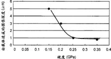
Fig. 9 is the curve map of expression measurement result of the surface damage degree of depth when the band member is rubbed by magnetic carrier.
Figure 10 is the synoptic diagram that adopts the imaging device of recording materials conveying belt.
Embodiment
Below, describe several form of implementation of the present invention with reference to the accompanying drawings in detail.As long as the crystallization degree of the crystalline resin material in the front (outer peripheral face) of band member, for example intermediate transfer belt or the recording materials conveying belt of crystalline resin material is than the height of the back side (inner peripheral surface), replace in their other form of implementation of alternative structure in part or all of structure, also can implement the present invention each form of implementation.
Therefore, the present invention not only can implement in the tandem imaging device that is provided with a plurality of photosensitive drums along recording materials conveying belt or intermediate transfer belt, and can implement in the imaging device of the single sensitization drum-type that is provided with single photosensitive drums.
In the form of implementation below, though will only describe the major part of the formation/transfer printing that relates to the toner picture, but by adding necessary apparatus, option or shell structure, the present invention can implement in the various application that comprise printer, various printing device, duplicating machine, facsimile recorder, Multi Role Aircraft or the like.
<first form of implementation 〉
Fig. 1 is the synoptic diagram of structure that is used to illustrate the electrophotographic imaging forming apparatus of first form of implementation, and Fig. 2 is the synoptic diagram that is used to be illustrated as the structure of picture portion and secondary transfer printing portion.
As shown in Figure 1, the imaging device 100 of first form of implementation is the tandem full color printer, wherein, disposes four Pa of imaging portion, Pb, Pc and Pd in the straight line portion as the intermediate transfer belt 7 of being with member.Particularly, the full color printer that adopts in this form of implementation is laser printer (" LBP5900 " that Canon Co., Ltd makes).
In the Pa of imaging portion, the toner of yellow is looked like to be formed on the photosensitive drums 1a as image bearing member, then, primary transfer is to rotation and form on the intermediate transfer belt 7 of annular.In the Pb of imaging portion, the toner of magenta is looked like to be formed on the photosensitive drums 1b, and on the toner picture with the mode primary transfer of the stack yellow to the intermediate transfer belt 7.In Pc of imaging portion and Pd, on photosensitive drums 1c and 1d, form the toner picture of cyan and the toner picture of black respectively, and similar, on the toner picture with the mode order primary transfer of the stack magenta to the intermediate transfer belt 7 with the situation of the Pb of imaging portion.
The toner of four looks of primary transfer to the intermediate transfer belt 7 looks like to be transported to the T2 of secondary transfer printing portion, at secondary transfer printing portion T2 place, the toner picture by secondary transfer printing in the lump to recording materials P.At secondary transfer printing portion T2 place by the toner picture of four looks of secondary transfer printing to the recording materials P by fixing device 25 heating and pressurizing and photographic fixing.Then, recording materials P is discharged to the outside of imaging device 100.
Except the toner of the yellow of the developing apparatus 4a that is used for being arranged on the Pa of imaging portion, the color of toner of black of toner, developing apparatus 4d that the toner and being used for of cyan that is used for being arranged on the developing apparatus 4c of the Pc of imaging portion is arranged on the Pd of imaging portion of magenta that is used for being arranged on the developing apparatus 4b of the Pb of imaging portion differs from one another, the Pa of imaging portion, Pb, Pc, Pd have roughly the same structure.In the following description, will be described as the Pd of picture portion,, be used to represent that the suffix d of the Reference numeral (symbol) of component parts (mechanism) will be made a, b and c by note respectively, be used for explaining relevant of component parts for other the Pa of imaging portion, Pb and Pc.
As shown in Figure 2, the Pd of imaging portion comprises the photosensitive drums 1d as the example of image bearing member.In the Pd of imaging portion, around photosensitive drums 1d, be provided with charging device 2d, exposure device 3d, developing apparatus 4d, primary transfer roller 5d and cleaning plant 6d.
By on the outer peripheral face of aluminum cylindrical shell, forming organic photoconductor (OPC) layer that constitutes by Organophotoreceptor material, preparation photosensitive drums 1d with negative charging polarity.Be equipped with the driving force that provides from CD-ROM drive motor (M3 Fig. 1) by branch, photosensitive drums 1d rotates with the processing speed of about 150mm/sec along the direction of arrow R1.
Developing apparatus stirs and passes through nonmagnetic toner is mixed 2 component developers that obtain with magnetic carrier, thereby toner is filled negative electricity.The toner of charging is carried on the surface of development sleeve 4s, forms chain by the magnetic force of fixed magnetic pole 4j, thereby rubs photosensitive drums 1d.Development sleeve 4s around fixed magnetic pole 4j along with photosensitive drums 1 in the opposite direction rotation of the sense of rotation of their contact position.
Toner comprises the material in polyester resin as the filled negative electricity of major constituent, has the volume averaging particle size of 6.2 μ m.Magnetic carrier is the resin magnetic carrier with volume averaging particle size of 35 μ m.
Power supply D4 is applied to development sleeve 4s and applies the developing voltage that (stack) exchanges the form of (AC) voltage on direct current (DC) voltage, thereby the static image drift of toner on the photosensitive drums 1d that has positive polarity for development sleeve 4s is moving.Thereby, with static as discharged-area development.
Power supply D1 applies positive direct current (DC) voltage to primary transfer roller 5d, thereby has negative electricity and the toner picture that is carried on the photosensitive drums 1d moves to intermediate transfer belt 7 by the T1 of primary transfer portion.
As shown in Figure 1, secondary transfer roller 11 is pressed in intermediate transfer belt 7 on the backing roll 10, so that form the secondary transfer printing T2 of portion between intermediate transfer belt 7 and secondary transfer roller 11.With intermediate transfer belt 7 on the toner picture overlappingly with recording materials P clamping and carry by in the process of secondary transfer printing portion, the toner picture is shifted to recording materials P from middle transfer belt.
By forming on metal-cored with semiconductor material NBR rubber and chlorohydrin rubber (hydrinrubber) foam rubber layer, preparation secondary transfer roller 11 as principal ingredient.The ASKER-C hardness of the semiconductor roller component that is obtained is 35, and the resistance of roller is 1 * 10
8Ω.
Power supply D2 applies positive constant voltage to secondary transfer roller 11, so that make the series circuit of transfer printing electric current by being formed by backing roll 10, intermediate transfer belt 7, recording materials P and secondary transfer roller 11.The part of transfer printing electric current is by the toner deposition portion of intermediate transfer belt 7, thereby the help toner moves to recording materials P from middle transfer belt 7.
<band member 〉
As shown in Figure 1, as the intermediate transfer belt 7 of the annular of the example of band member by as driven roller 13, backing roll 10 and idler roller 12 supportings of the example of rotatable member and extend.Intermediate transfer belt 7 is driven by CD-ROM drive motor M3, so that rotate along the direction of arrow R2.
As shown in Figure 5, when when being carried on developer on the development sleeve 4s with the developing electrostatic image on the photosensitive drums 1d, in some cases, a part of magnetic carrier (c) that is included in the developer deposits on the photosensitive drums 1 with toner (t).
With reference to Fig. 5, when the toner picture when photosensitive drums 1d is transferred on the intermediate transfer belt 7, be carried on magnetic carrier c on the photosensitive drums 1d with toner t, by with the friction on the surface of intermediate transfer belt 7, can form scratch.This scratch causes the inhomogeneous of transfer printing, thereby reduces the pick-up performance of picture quality and reduction intermediate transfer belt 7.
Therefore, even selecting to have, intermediate transfer belt 7 needs ought in the process of high speed rotating, be pulled the material that also can not cause big abrasive skin hardness and anti-wear property (anti-bending performance) by magnetic carrier c.
As shown in Figure 6,, rotatably insert the roller 12e and the 12f that form by the aldehyde resin material, so that the lateral deviation of control generation when middle transfer belt 7 driven rolls 13 drive at the both ends of the turning axle of idler roller 12.
Therefore, in the process of the high speed rotating of intermediate transfer belt 7, the part with roller 12e contacts with 12f of intermediate transfer belt 7 is moved by the horizontal direction along intermediate transfer belt 7 and is outstanding, thereby intermediate transfer belt 7 is bent (bending) and distortion repeatedly with little radius.
For forming one deck and forming the two edges portion of inner peripheral surface of the intermediate transfer belt 7 of seamless shape, be provided for limiting the inwardly outstanding rib that move of intermediate transfer belt 7 on the rotation direction of intermediate transfer belt 7, make it extending continuously in full week along intermediate transfer belt 7. Rib 7e and 7f are that 70 urethane rubber forms by JIS-A hardness, and width is 5mm, and thickness is 1mm, and with rib 7e and 7f bonding to continuously on the inner peripheral surface of intermediate transfer belt 7 in full week along intermediate transfer belt 7.
For this reason, rib 7e and 7f are in the scope that satisfies anti-wear property (characteristic), form by enough soft material, but in the borderline region that rib 7e and 7f are set, in the high speed rotating process of intermediate transfer belt 7, cause the difference of flex stiffiness, concentrate thereby rib 7e and 7f are subjected to weak stress.
Therefore,, need be chosen in the high speed rotating process of intermediate transfer belt 7, can show sufficient anti-fatigue performance, resist in the borderline region of bonding rib 7e and 7f the material of the bending stress that produces repeatedly simultaneously for intermediate transfer belt 7.
And then, when having selected material mistakenly, in low temperature environment, under the situation of operation intermediate transfer belt 7, can in the borderline region of bonding rib 7e and 7f, produce slight crack (breaking) for a long time.
As the material that is used for intermediate transfer belt 7, adopt polyimide resin material traditionally as thermoset resin material.Yet this material itself is very expensive, and in addition, this drawing abillity and production performance are poor, therefore causes the cost of parts to increase.
Therefore, for less use, number to be processed is few and do not need to have for the type with the imaging device of the comparable durability of polyimide resin material, has proposed to be provided with on the surface of the thermoplastic resin material with low skin hardness the scheme of hard coating surface layer.
Yet, in this case, the step of superficial layer need be set, thereby, compare with the cost of the polyimide resin material of single layer structure even when adopting the resin material of common purposes, the intermediate transfer belt that is obtained also is expensive.
In these environment, the inventor has developed a kind of intermediate transfer belt, and described intermediate transfer belt forms one deck thermoplastic resin material, and by procedure of processing is designed, can take into account fatigue resistence, flex stiffiness and anti-wear property.The inventor provides by adopting crystalline thermoplastic resin material, only improving the intermediate transfer belt 7 of surface crystallization degree.By adopting polyetheretherketone (PEEK) resin material, adjust the crystallization degree, thereby make intermediate transfer belt 7 have skin hardness in the front, and have skin hardness smaller or equal to 0.20GPa at its back side more than or equal to 0.25GPa.
In the present invention, the material as can be used in the band member can adopt the crystalline resin material of any thermoplasticity.For example, can adopt polyetheretherketone, polyphenylene sulfide, polybutylene terephthalate etc. aptly.
And then, for these resin materials,, can add the attritive powder of at least a organic or inorganic in order to give their electric conductivity.As inorganic attritive powder, can adopt inorganic spherical subparticle, for example carbon black powders, magnesium oxide powder, magnesium fluoride powder, SiO 2 powder, alumina powder, boron nitride powder, aluminium nitride powder, titanium dioxide powder.The attritive powder that adds preferably can be sphere, and preferably can have the particle size smaller or equal to 1.0 μ m, so that keep the surface flatness of the resin material of interpolation attritive powder.
Kind, particle size and content for such attritive powder that will add have no particular limits, as long as this attritive powder can give basic unit aforesaid electric conductivity.Yet total addition of such attritive powder preferably can be about 5~40wt.% with respect to base resin material, is preferably 5~25wt.% especially.
Thereby, can realize following effect.
(1) the band member that is obtained has enough durabilities of the resistance various external force relevant with fatigue resistance with physical strength, anti-wear property and warp resistance.
(2) by only increasing the surface crystallization degree, the skin hardness that is obtained is brought up to more than or equal to predetermined value, thereby, the generation of the damage of the band member that causes by contact member can be prevented, and good pick-up performance can be kept.
(3) compare with the band and the sandwich tape that are formed by the polyimide resin material that mainly is used as the intermediate transfer carrying material traditionally, band member of the present invention is more cheap.
The manufacture method of<band member 〉
Below description is comprised the steps the manufacture method of the band member of (1) to (5).
(1) with reference to Fig. 3, polyetheretherketone (" VICTREX PEED450P " with 85 mass parts, make by Victrex plc) and the conductive carbon black (acetylene black of 15 mass parts, " DENKABLACK ", make by DENKI KAGAKU KOGYO KABUSHIKI KAISHA) be supplied to diaxon to mix to rub extruder 150, and in the melt temperature that is not less than resin material and be not higher than under the cylinder barrel temperature of the temperature that causes thermal degradation, in 340 to 400 ℃ of scopes, mix particularly and rub, carry out melt extruded then.Cut out method by so-called hawser, this molten resin material forms the hawser 180 of diameter 2mm by round nozzle 160.At cooling end 170 waters hawser 180 is cooled off.Then, hawser 180 is cut into the pill that has about 2mm length respectively, thereby makes the granular pill of 2mm size at cutting part 190.
(2) by in band manufacturing equipment as shown in Figure 4, using these pills, make seamless band.With reference to Fig. 4, the band manufacturing equipment by hopper 200, extruder 210, gear-type pump 220, mould 230, as the cooling device 240 of feature of the present invention, the drawing device 250 and the cutting machine 260 that are used for drawing with drum film constitute.At first, the pill for preparing is above packed into hopper 200 and by extruder 210 melt extruded.Extruder 210 is simple helix extruders, and is similar with the situation of extruder 150 recited above, is set in 340 to 400 ℃ temperature.Spray the resin material of the fusion that is obtained by gear-type pump 220 with constant amount, subsequently, carry out the melt extruded of molten resin material with tubular form by the mould 230 that is set in 385 ℃.Consider the generation of sealing wire etc., mould 230 comprises the spiral mould, and by being heated around mould 230 winding of band-type well heaters.When keeping drum and adopting drawing device 250 to draw, by adopting cooling device 240 as shown in Figure 7, with the molten resin material melting and solidification cylindraceous that is obtained.
(3) with reference to Fig. 7 cooling device is described below.The inside surface of the pipe of molten condition is contacted with the core 32 that is set in 90 ℃ temperature, so that cool off fast, simultaneously, the external heating device 33 that employing is set in 260 ℃ temperature cools off the outside surface of pipe gradually, thereby, the resin material that is used for described pipe is controlled at the crystallization degree of inside surface with at the crystallization degree of outside surface.Pack in core 32 unshowned well heater and unshowned water-cooling apparatus are so that can set the temperature on the mirror finish surface of the core 32 that is formed by copper arbitrarily in the scope of cooling water temperature to 300 ℃.Provide the adjustment chilled water to feed pipe 32i, and make chilled water pass through vent pipe 32e, temperature bath, ebullator and feed pipe 32i circulation.Carry out the curing and the phase transformation of molten resin material, so that provide the cooling processing that differs from one another to positive layer and back layer, thus the resin strip member PE of the tubulose of the about 150 μ m of formation thickness, girth 700mm.The band member passes cooling end with the speed of 1m/min.
(4) the resin strip member PE of the tubulose that is cooled with cutting machine 260 cutting so that make its width with 400mm, then, with rotation status polished film friction, thereby makes it be subjected to surface finish and by mirror finish.
(5) for each of the two edges portion of interior (week) face of the resin strip member PE of mirror finish, at the bonding thickness 1mm of whole week of band member PE and the ameripol plate of width 5mm, so that be formed for preventing the rib (7e among Fig. 6,7f) that crawls.
As mentioned above, in the present invention, just in step (2), the molten resin material melt extruded is being become tubular form so that after adjusting thickness, by positive layer and back layer being adopted the cooling processing that differs from one another, the described crystallization degree in control back.
Here, hardness and crystallization degree will be described.By cooling off gradually, can improve the crystallization degree of crystalline resin material, thereby hardness is increased.On the other hand, when the crystalline resin material of quick cooling, the crystallization degree reduces.As a result, hardness reduces.
<embodiment and comparative example 〉
Fig. 8 is the curve map of actual range that is used for the skin hardness of explanation positive (outer peripheral face) and the back side (inner peripheral surface), and Fig. 9 is the curve map that is used to illustrate the measurement result of the surface damage degree of depth that the friction by magnetic carrier causes.
In embodiment 1, the temperature of external heating device is set at 260 ℃, and, the temperature of core is set at 90 ℃.
In embodiment 2, the temperature of external heating device is set at 130 ℃, thereby compares with embodiment 1, the cooling velocity at inside surface place reduces.
In embodiment 3, the temperature of external heating device is set at 180 ℃, thereby compares with embodiment 1, the cooling velocity of outer surface improves.
In embodiment 4, the temperature of core is set at 130 ℃, and, the temperature of external heating device is set at 180 ℃.
In comparative example 1, the temperature of core is set at 260 ℃, thereby compares with embodiment 2, the cooling velocity at inside surface place reduces.
In comparative example 2, the temperature of core is set at 180 ℃, thereby compares with embodiment 2, the cooling velocity at the inside surface place reduces.
In comparative example 3, the temperature of core is set at 180 ℃, and, the temperature of external heating device is set at 180 ℃.
In comparative example 4, the temperature of core is set at 130 ℃, and, the temperature of external heating device is set at 130 ℃.
In comparative example 5, the temperature of core is set at 90 ℃, and, the temperature of external heating device is set at 90 ℃.
Table 1

The intermediate transfer belt 7 of embodiment 1 is cut into two test films, and each test film has the size of 10mm * 10mm.A test film is bonded on the sample bench as bonding plane with its front.Another test film is bonded on the sample bench as bonding plane with its back side.It is 20 μ m that each test film is whittled into thickness, and is arranged in the X-ray diffraction device (being made by RigakuCorporation).Spending in the sweep limits of 45 degree from 5, with the X-ray diffraction pattern of each test film of scan speed measurement of 5 degree/min, so that calculating crystallization degree.
By adopting so-called peak separation method to calculate the crystallization degree, in described peak separation method, compare by the peak value of fractional crystallization portion and with the wave spectrum of amorphous portion and the wave spectrum of crystallization portion, determine the crystallization degree.For polyetheretherketone, in the neighborhood of 18.6 degree, 21 degree, 22.8 degree and 28.8 scanning angles of spending, observe the peak value of crystallization portion.
As shown in table 1, in embodiment 1, in the front of being cooled off gradually, the crystallization degree is 30%, and at the back side of being cooled off fast, the crystallization degree is 6%.
In embodiment 2, in the front of being cooled off gradually, the crystallization degree is 30%, and at the back side that quilt cools off slowly than embodiment 1, the crystallization degree is 12%.
In embodiment 3, in the front that quilt cools off soon than embodiment 1, the crystallization degree is 18%, and at the back side of being cooled off fast, the crystallization degree is 5%.
In embodiment 4, in the front that quilt cools off soon than embodiment 1, the crystallization degree is 18%, and at the back side that quilt cools off slowly than embodiment 1, the crystallization degree is 12%.
In comparative example 1, in the front of being cooled off gradually, the crystallization degree is 30%, and at the back side that quilt cools off slowly than embodiment 2, the crystallization degree is 30%.
In comparative example 2, in the front of being cooled off gradually, the crystallization degree is 30%, and at the back side that quilt cools off slowly than embodiment 2, the crystallization degree is 18%.
In comparative example 3, in the front that quilt cools off soon than embodiment 1, the crystallization degree is 18%, and at the back side that quilt cools off slowly than embodiment 2, the crystallization degree is 18%.
In comparative example 4, in the front that quilt cools off soon than embodiment 1, the crystallization degree is 12%, and at the back side of being cooled off similar to Example 2ly, the crystallization degree is 12%.
In comparative example 5, in the front that quilt cools off soon than embodiment 1, the crystallization degree is 6%, and at the back side of being cooled off similar to Example 3ly, the crystallization degree is 6%.
Each intermediate transfer belt 7 is cut into two test films, the skin hardness of the front and back of test film is measured according to continuous rigidity assay method by adopting ultra micro sclerometer (" Nano Indenter " made by MTI Systems Corporation).Adopt angle between the adjacent seamed edge of triangle side be the triangular tapers of 115 degree diamond penetrator, be so-called Berkovich pressure head, as pressure head.In vibration frequency is that the desired value of 45Hz, displacement amplitude is to measure under the condition of 1nm, till the degree of depth reaches 2.0 μ m.Change measuring point, carry out 10 times and measure.The mean value that adopts 10 measuring points is as the skin hardness value.Measurement result is as shown in table 2.
Table 2

As shown in table 2, in embodiment 1, the skin hardness of intermediate transfer belt 7 is 0.35GPa in the front, is 0.15GPa overleaf.
In embodiment 2 to 4 and comparative example 1 to 5, the skin hardness of intermediate transfer belt 7 is basically with corresponding in the value of front and crystallization degree overleaf.
Then, each intermediate transfer belt 7 of embodiment 1 to 4 and comparative example 1 to 5 is installed in as shown in Figure 1 the imaging device 100, and carries out 30 * 10 respectively
4Open the imaging of common paper.
In table 3, express situation about cracking and the situation that the cleaning fault takes place.
Table 3

And then confirm that the intermediate transfer belt 7 of embodiment 1 is through 300 * 10
4Crackle and cleaning fault do not take place in the imaging test of opening.Thereby, compare with the traditional intermediate transfer belt 7 that forms with the polyetheretherketone of one deck structure respectively, even in imaging 30 * 10
4Under the situation of opening, the intermediate transfer belt 7 of embodiment 1 aspect the abrasive size and the degree of depth that are caused by the magnetic carrier of irony, the Magnaglo in the atmosphere, inorganic subparticle etc., also improves.And then, in embodiment 1 to 4, do not have to reduce pick-up performance, thereby the transfer printing remaining toner is cleared up scraper (19b shown in Fig. 1) and is removed fully on middle transfer belt 7 with respect to toner.
Each intermediate transfer belt 7 of embodiment 1 to 4 forms one deck by polyetheretherketone respectively.And then, at the crystallization degree of positive (outside surface) more than or equal to 16%, and, in the skin hardness of positive (outside surface) more than or equal to 0.25GPa.The crystallization degree of (inside surface) is smaller or equal to 12% overleaf, and the skin hardness of (inside surface) is smaller or equal to 0.20GPa overleaf.In such structure, in imaging 30 * 10
4In the process of opening, do not crack and the cleaning fault takes place.
Each intermediate transfer belt 7 of comparative example 1 to 3 forms one deck by polyetheretherketone respectively.Yet the crystallization degree of (inside surface) is not below or equal to 12% overleaf, and the skin hardness of (inside surface) is not below or equal to 0.20GPa overleaf.In such structure, reaching 30 * 10 up to the imaging number
4In the process till opening, crack.
Comparative example 4 and each intermediate transfer belt 7 of 5 form one deck by polyetheretherketone respectively.Yet the crystallization degree in front (outside surface) is not more than and equals 16%, and the skin hardness in front (outside surface) is not more than and equals 0.25GPa.In such structure, reaching 30 * 10 up to the imaging number
4In the process till opening, the cleaning fault takes place.
Relation between the generation of the skin hardness of front and back and crackle and cleaning fault is shown in table 4.
Table 4
C1
* 1: 1 * 10
4Crack when opening.
B
* 2: 10 * 10
4Crack when opening.
A
* 3: 30 * 10
4Do not crack and clear up fault when opening.
C2
* 4: 5 * 10
4Produce the cleaning fault when opening.
As shown in Figure 8, the skin hardness of the intermediate transfer belt 7 of embodiment 1 to 4 and comparative example 1 to 5 is linear distribution with respect to the value of the crystallization degree of polyetheretherketone (PEEK).
In the imaging device 100 of first form of implementation, for the skin hardness of positive (outside surface), actual range is more than or equal to 0.25GPa.This is because when the skin hardness in front during less than 0.25GPa, the abrasive size and the degree of depth that are caused by the magnetic carrier of irony, the Magnaglo in the atmosphere, inorganic subparticle etc. have exceeded tolerable scope, cause because the glossiness that the imaging of accumulation causes or the excessive change of surfaceness.And then this is because as shown in Tables 3 and 4, less than 30 * 10
4Cause clearing up skin hardness that phenomenon of the failure takes place in the imaging of opening for less than 0.25GPa.
And then for the skin hardness of inside surface, be for the skin hardness at the back side, actual range is smaller or equal to 0.20GPa.This is that the material that is used for intermediate transfer belt becomes fragile, thereby does not have enough fatigue resistances and enough warp resistance intensity because the skin hardness when the back side surpasses 0.20GPa.And then as shown in Tables 3 and 4, this is because the backside surface hardness that causes crackle to produce surpasses 0.20GPa.
In imaging device 100, when middle transfer belt 7 at the crystallization degree in front more than or equal to 16% the time, therefore positive skin hardness, satisfies excellent function more than or equal to 0.25GPa for surface property.
And then, when the crystallization degree of inside surface smaller or equal to 12% the time, therefore the skin hardness at the back side satisfies good durability smaller or equal to 0.20GPa.
Below, in order to confirm and study surface property, adopt imaging device shown in Figure 1 100 to carry out experiment about the shortening of the surface property of the intermediate transfer belt 7 of embodiment 1 to 4 and comparative example 1 to 5.
Particularly, between photosensitive drums and each intermediate transfer belt 7, force to apply magnetic carrier, described magnetic carrier is by with magnetic metal oxide with the nonmagnetic metal oxide is mixed in the phenolic adhesive resin material and the processing that makes potpourri stand polymerization is made.Then, under the halted state of intermediate transfer belt 7, rotation drives photosensitive drums 1d.Then, measure the surface damage degree of depth by laser microscope (" VK-8500 " made by KEYENCE CORPORATION) by on intermediate transfer belt 7, forming with the magnetic carrier friction.
As shown in Figure 9, Zheng Mian skin hardness is relative to each other with the degree of depth of the surface damage that is caused by magnetic carrier.That is, skin hardness is high more, and the surface damage of intermediate transfer belt 7 is more little.This can be considered to because such cause: under the low situation of the skin hardness in front, intermediate transfer belt 7 by the T1 of primary transfer portion produces big plastic yield, but, skin hardness in the front is higher than under the situation of " as the 0.25GPa of boundary value ", and intermediate transfer belt 7 does not produce plastic yield.
Therefore, for the skin hardness in front intermediate transfer belt 7, even when the surface damage of middle transfer belt 7, damage also less more than or equal to 0.25GPa.Therefore, in imaging device 100, good pick-up performance and preferable image characteristic have been guaranteed.
About the crackle of intermediate transfer belt 7, make under the situation of crystallization degree increase by the whole pipe that cools off gradually with the molten condition placement, itself enbrittles resin material.Because this fragility near the local deformation the rib (7e among Fig. 6,7f), cracks.
In embodiment 1 to 4, have only positive crystallization degree to increase, thereby the front shows fragility, but the part from the center to the back side have hardness, that is, be amorphous state.Therefore, whole thickness partly has toughness to a certain degree.Therefore, even under the situation of local deformation, described band also has pliability, thereby can think and do not crack.
Incidentally, for the skin hardness in front, when the skin hardness in front surpassed 0.40GPa, the photosensitive drums that friction has the belt surface of high rigidity was subjected to very big influence.Therefore, Zheng Mian skin hardness on be limited to smaller or equal to 0.40GPa.Less for the influence to photosensitive drums, positive skin hardness is preferably smaller or equal to 0.35GPa.
And then, for the skin hardness at the back side,, can produce following problems when the skin hardness at the back side during less than 0.10GPa.That is, the back side of band member is configured to and take up member (roller etc.) friction that is used for the tension band member.When hardness excessively reduced, by the friction between the back side and the take up member, positive wear intensity extremely increased, thereby had shortened the serviceable life of band member.Therefore, the skin hardness at the back side need be more than or equal to 0.10GPa.
And then, the tandem imaging device has been described in first form of implementation, but, the intermediate transfer belt 7 of embodiment 1 to 4 also can be used in the imaging device of one (single) bulging type, in such imaging device, the photosensitive drums that is provided with a plurality of developing apparatuss is contacted with intermediate transfer belt.
The intermediate transfer belt 7 of embodiment 1 to 4 not only can be used as intermediate transfer belt, and can be with acting on the recording materials conveying belt of carrying recording materials.
As the crystalline thermoplastic resin material that can be used in intermediate transfer belt 7,, can adopt any resin material as long as it can satisfy above-mentioned electricity and mechanical property.
For polyetheretherketone, polyphenylene sulfide and polybutylene terephthalate, can obtain to have the intermediate transfer belt of the practicality of different crystallization degree at front and back.And then, can think that polyethylene terephthalate, tygon, polypropylene, polyamide etc. are suitable for.
And then, for these resin materials,, can add at least a organic or inorganic attritive powder in order to give electric conductivity.For example, can adopt such as inorganic spherical subparticles such as carbon black powders, magnesium oxide powder, magnesium fluoride powder, SiO 2 powder, alumina powder, boron nitride powder, aluminium nitride powder and titanium dioxide powders.Attritive powder can be preferably spheric grain, and can preferably have the particle size smaller or equal to 1.0 μ m, so that keep the surface smoothness of the resin material of adding attritive powder.
Determine kind, particle size and the content of such attritive powder that will add, so that guarantee the electric conductivity that basic unit is required.Yet total addition of such attritive powder preferably can be about 5~40wt.% with respect to base resin material, is preferably 5~25wt.% especially.
In embodiment 1 to 4,, also can adopt thermoset resin material though adopted thermoplastic resin material.In this case, come the crystallization control degree,, thereby can realize similar effects so that the positive skin hardness and the skin hardness at the back side are dropped in the above-mentioned scope by the condition of regulating in the heating process.
Incidentally, as the spy open the 2001-047451 communique described, traditional imaging device has used the intermediate transfer belt with single layer structure that adopts the polyimide resin material.This is because the polyimide resin material has high elastic modulus, and such as various characteristics excellences such as thermotolerance, wear resistance, creep resistances.Yet the polyimide resin material is a thermoset resin material, thereby, can not carry out melt extruded, and also be difficult to thickness is adjusted.Thereby, need very high manufacturing cost.
And then, as the spy open the 2000-330390 communique described, traditional imaging device has adopted the intermediate transfer belt that has on thin metal plate layer the sandwich construction that forms elastic rubber layer.Yet this number of the step that comprises stacked, coating, thickness adjusted etc. with intermediate transfer belt of sandwich construction increases, thereby compares with the situation of the polyimide resin material of single layer structure, and the manufacturing cost that needs is higher.
Owing to these reasons, in the not too high undersized imaging device of frequency of utilization, needing to adopt can be with the thermoplastic resin material of low cost manufacturing.
The spy of Miao Shuing opens among the 2005-112942 in the above, has described the intermediate transfer belt of employing as the polyetheretherketone (PEEK) of the example of crystalline thermoplastic resin material.Polyetheretherketone is inferior to the polyimide resin material, but chemical resistance, anti-fatigue performance, toughness, anti-wear property, sliding, thermotolerance (at 70 ℃ creep properties) excellence, and at high temperature have high elastic modulus, and impact resistance and flex stiffiness are also excellent.Polyetheretherketone is a thermoplastic resin material, thereby can adopt for example melt extruded, the adjustment of stretching thickness etc. continuously and have large-duty production technology.Polyetheretherketone is crystalline condensate, still, by the design to molecular structure, can suppress its crystallization degree aptly, thereby also can have the characteristic as amorphous polymer.
The crystalline thermoplastic resin material that can be used to intermediate transfer belt is not limited to polyetheretherketone.Open the spy and to have described the intermediate transfer belt of a kind of employing in the 2006-069046 communique as the polyphenylene sulfide (PPS) of the example of crystalline thermoplastic resin material.
The crystalline thermoplastic resin material of part that comprises polyetheretherketone in the time of in being used in as the mechanical part of engineering plastics, has excellent physical strength and processing characteristics simultaneously.
Yet, when after such resin material being processed into intermediate transfer belt, being actually used in the imaging device with seamless layer structure, compare with the polyimide resin material as in the comparative example 5, anti-wear property and sliding deficiency, as a result, the imaging that is identified by accumulation causes surface gloss to reduce and surfaceness will soon worsen.
Therefore, for as in the comparative example 1, by in the melt extruded process, cooling off whole resin material gradually improving the crystallization degree, and improve positive skin hardness whereby, study so that guarantee wear resistance and sliding.
Yet, when as comparative example 1, the crystallization degree of whole resin material being brought up to the degree of guaranteeing required wear resistance, find that fatigue resistance, pliability and warp resistance intensity reduce, thereby shortened the replacing life-span of band member.Be set under the two edges portion of the inner peripheral surface of band member, the state that extends continuously along the whole week of band member at the rib that is used for the motion in the axial direction of check strap member, when the band member rotated in low temperature environment, under high-tension continuously, finding had the tendency that cracks in the root boundary portion office of outstanding rib.
On the other hand, in embodiment 1 to 4, particularly in embodiment 1, only improved the crystallization degree of superficial layer at the outer peripheral face place that is subjected to the magnetic carrier friction of intermediate transfer belt, thereby, the wear resistance and the friction resistant performance of intermediate transfer belt strengthened.
And then, the part from the central core to the inner peripheral surface of mainly bearing tension force and bending force of intermediate transfer belt keeps high amorphous microstructure state, so that avoid concentrated, thereby guarantee fatigue resistance, pliability and the flexural strength of intermediate transfer belt at the stress at crystal boundary place.
Therefore, can improve the anti-wear property and the friction resistant performance in the front of intermediate transfer belt, and can not weaken fatigue resistance, pliability and the warp resistance intensity that adopts thermoplastic resin material to form the intermediate transfer belt of seamless layer.
Incidentally, positive skin hardness as shown in Figure 9, is meant that the scratch that is caused by magnetic carrier increases boundary value before suddenly more than or equal to the such numerical definiteness of 0.25GPa.In the above description, the band member is taked the form of intermediate transfer belt.Yet, also can be with acting on the recording materials conveying belt of carrying recording materials according to band member of the present invention.Particularly, as shown in figure 10, recording materials conveying belt 40B absorption is also carried the recording materials P that carries and pass in proper order the Pa of imaging portion, Pb, Pc and Pd from alignment roller 2300.At the Pa of imaging portion, form yellow toner picture and also be transferred on the recording materials, then,, form the toner picture of magenta and be transferred on the toner picture of the yellow on the recording materials P in the mode of stack at the Pb of imaging portion.At Pc of imaging portion and Pd, form the toner picture of cyan and the toner picture of black respectively, and be transferred in proper order on the toner picture of the transfer printing before on the recording materials P in the mode of stack.
Transfer printing the recording materials P of toner picture of four kinds of colors by fixing device 1700 heating, pressurization so that with its lip-deep toner as photographic fixing, then, be discharged to the outside of imaging device 500.Even when being used in band member of the present invention in such imaging device, also can realize effect of the present invention.
Although invention has been described with reference to structure disclosed herein,, the present invention is not limited to aforementioned details, and the application should cover the interior remodeling or the variation of scope of described improved purpose or claims.
Claims (18)
1. intermediate transfer belt member, this intermediate transfer belt member uses with electrophotographic imaging forming apparatus, and it is rotatably mounted by a plurality of rotating parts, be used to carry the toner picture that is developed on image mounting member by the developer that includes magnetic carrier, described intermediate transfer belt member comprises:
By the layer that crystalline resin material forms, described layer has outer peripheral face and inner peripheral surface,
Wherein, described layer has more than or equal to 0.25GPa and smaller or equal to the hardness of 0.40GPa at outer peripheral face, and has more than or equal to 0.10GPa and smaller or equal to the hardness of 0.20GPa at inner peripheral surface.
2. intermediate transfer belt member as claimed in claim 1 is characterized in that, described layer has than described layer at the high crystallization degree of the crystalline resin material of inner peripheral surface at the crystalline resin material of outer peripheral face.
3. intermediate transfer belt member as claimed in claim 1 is characterized in that, described crystalline resin material is a thermoplastic resin material.
4. intermediate transfer belt member as claimed in claim 1, it is characterized in that, described intermediate transfer belt member is provided with inwardly outstanding rib, be used to limit the motion of described intermediate transfer belt member on the rotation direction, described rib is the both sides of described inner peripheral surface extending continuously along described intermediate transfer belt member in full week.
5. intermediate transfer belt member as claimed in claim 1 is characterized in that, described crystalline resin material is polybutylene terephthalate, polyphenylene sulfide or polyetheretherketone.
6. intermediate transfer belt member as claimed in claim 1 is characterized in that, described layer is formed by polyetheretherketone, and, have crystallization degree at outer peripheral face more than or equal to 16%, have crystallization degree at inner peripheral surface smaller or equal to 12%.
7. an imaging device is used for forming the toner picture on recording materials, and described device comprises:
The intermediate transfer belt member, this intermediate transfer belt member is rotatably mounted by a plurality of rotating parts, is used to carry the toner picture that is developed on image mounting member by the developer that includes magnetic carrier;
Transfer device, this transfer device are used for the toner picture is transferred to recording materials from described intermediate transfer belt member;
Wherein, described intermediate transfer belt member has the layer that is formed by crystalline resin material, and described layer has outer peripheral face and inner peripheral surface,
Wherein, described layer has more than or equal to 0.25GPa and smaller or equal to the hardness of 0.40GPa at outer peripheral face, and has more than or equal to 0.10GPa and smaller or equal to the hardness of 0.20GPa at inner peripheral surface.
8. device as claimed in claim 7 is characterized in that, described layer has than described layer at the high crystallization degree of the crystalline resin material of inner peripheral surface at the crystalline resin material of outer peripheral face.
9. device as claimed in claim 7 is characterized in that, described crystalline resin material is a thermoplastic resin material.
10. device as claimed in claim 7, it is characterized in that, described intermediate transfer belt member is provided with inwardly outstanding rib, be used to limit the motion of described intermediate transfer belt member on the rotation direction, described rib is the both sides of described inner peripheral surface extending continuously along described intermediate transfer belt member in full week.
11. device as claimed in claim 7 is characterized in that, described crystalline resin material is polybutylene terephthalate, polyphenylene sulfide or polyetheretherketone.
12. device as claimed in claim 7 is characterized in that, described layer is formed by polyetheretherketone, and, have crystallization degree at outer peripheral face more than or equal to 16%, have crystallization degree at inner peripheral surface smaller or equal to 12%.
13. an imaging device is used for forming the toner picture on recording materials, described device comprises:
The band member, this band member is rotatably mounted by a plurality of rotating parts, is used to carry recording materials;
Transfer device, this transfer device are used for and will look like to be transferred to recording materials on the described band member at the toner that develops on the image mounting member by the developer that includes magnetic carrier,
Wherein, described band member has the layer that is formed by crystalline resin material, and described layer has outer peripheral face and inner peripheral surface,
Wherein, described layer has more than or equal to 0.25GPa and smaller or equal to the hardness of 0.40GPa at outer peripheral face, has more than or equal to 0.10GPa and smaller or equal to the hardness of 0.20GPa at inner peripheral surface.
14. device as claimed in claim 13 is characterized in that, described layer has than described layer at the high crystallization degree of the crystalline resin material of inner peripheral surface at the crystalline resin material of outer peripheral face.
15. device as claimed in claim 13 is characterized in that, described crystalline resin material is a thermoplastic resin material.
16. device as claimed in claim 13, it is characterized in that, described band member is provided with inwardly outstanding rib, is used to limit the motion of described band member on the rotation direction, and described rib is the both sides of described inner peripheral surface extending continuously along described band member in full week.
17. device as claimed in claim 13 is characterized in that, described crystalline resin material is polybutylene terephthalate, polyphenylene sulfide or polyetheretherketone.
18. device as claimed in claim 13 is characterized in that, described layer is formed by polyetheretherketone, and, have crystallization degree at outer peripheral face more than or equal to 16%, have crystallization degree at inner peripheral surface smaller or equal to 12%.
Applications Claiming Priority (3)
| Application Number | Priority Date | Filing Date | Title |
|---|---|---|---|
| JP2007232921 | 2007-09-07 | ||
| JP2007232921A JP5084412B2 (en) | 2007-09-07 | 2007-09-07 | Image forming apparatus and intermediate transfer belt |
| JP2007-232921 | 2007-09-07 |
Publications (2)
| Publication Number | Publication Date |
|---|---|
| CN101382763A CN101382763A (en) | 2009-03-11 |
| CN101382763B true CN101382763B (en) | 2011-04-20 |
Family
ID=40431980
Family Applications (1)
| Application Number | Title | Priority Date | Filing Date |
|---|---|---|---|
| CN2008102158620A Expired - Fee Related CN101382763B (en) | 2007-09-07 | 2008-09-05 | Belt member and image forming apparatus using the belt member |
Country Status (3)
| Country | Link |
|---|---|
| US (1) | US8050604B2 (en) |
| JP (1) | JP5084412B2 (en) |
| CN (1) | CN101382763B (en) |
Families Citing this family (18)
| Publication number | Priority date | Publication date | Assignee | Title |
|---|---|---|---|---|
| WO2007046218A1 (en) * | 2005-10-20 | 2007-04-26 | Konica Minolta Business Technologies, Inc. | Intermediate transfer body, method for manufacturing intermediate transfer body, and image-forming device |
| JP5486217B2 (en) * | 2008-06-02 | 2014-05-07 | セイコーエプソン株式会社 | Multilayer belt |
| JP5423155B2 (en) | 2008-10-01 | 2014-02-19 | 株式会社リコー | Image forming apparatus |
| JP4760935B2 (en) * | 2009-03-12 | 2011-08-31 | コニカミノルタビジネステクノロジーズ株式会社 | Intermediate transfer belt and image forming apparatus |
| JP2010249906A (en) * | 2009-04-13 | 2010-11-04 | Shin Etsu Polymer Co Ltd | Endless belt and image forming apparatus |
| JP5566057B2 (en) * | 2009-07-28 | 2014-08-06 | キヤノン株式会社 | Image forming apparatus |
| JP2011141365A (en) * | 2010-01-06 | 2011-07-21 | Canon Inc | Cylindrical seamless belt for electrophotography, and method for manufacturing the same |
| JP5538954B2 (en) * | 2010-02-26 | 2014-07-02 | キヤノン株式会社 | Conductive belt and electrophotographic apparatus |
| JP6218348B2 (en) * | 2010-12-10 | 2017-10-25 | 日立化成株式会社 | Lithium ion secondary battery and manufacturing method thereof |
| JP6271845B2 (en) | 2012-04-04 | 2018-01-31 | キヤノン株式会社 | Image forming apparatus and intermediate transfer unit |
| JP5814222B2 (en) * | 2012-12-28 | 2015-11-17 | 京セラドキュメントソリューションズ株式会社 | Positively charged single layer type electrophotographic photosensitive member and image forming apparatus |
| US9158251B2 (en) * | 2013-08-30 | 2015-10-13 | Canon Kabushiki Kaisha | Film and image heating device using film |
| JP2015187625A (en) * | 2014-03-26 | 2015-10-29 | 株式会社沖データ | Transfer belt, transfer belt unit, and image forming apparatus |
| JP6369172B2 (en) | 2014-07-02 | 2018-08-08 | 株式会社リコー | Intermediate transfer belt |
| JP6331868B2 (en) * | 2014-08-19 | 2018-05-30 | 富士ゼロックス株式会社 | Extruded tubular body, tubular body unit, intermediate transfer body, recording medium transport body, and image forming apparatus |
| JP2016057582A (en) | 2014-09-12 | 2016-04-21 | キヤノン株式会社 | Image forming apparatus |
| JP6855762B2 (en) * | 2016-01-18 | 2021-04-07 | Mccアドバンスドモールディングス株式会社 | Extrusion molding method for sheet-shaped members for image forming equipment |
| CN107219732A (en) * | 2017-06-21 | 2017-09-29 | 苏州恒久光电科技股份有限公司 | High rigidity organic photoconductor coating method and its obtained color laser optical conductor |
Family Cites Families (24)
| Publication number | Priority date | Publication date | Assignee | Title |
|---|---|---|---|---|
| JP3673583B2 (en) | 1995-02-10 | 2005-07-20 | キヤノン株式会社 | Transfer material carrying member |
| US5633702A (en) | 1995-02-10 | 1997-05-27 | Canon Kabushiki Kaisha | Transfer material carrying member and image-forming apparatus comprising such transfer material carrying member |
| JPH10207250A (en) * | 1997-01-23 | 1998-08-07 | Tokai Rubber Ind Ltd | Semiconducting plastic endless belt |
| JP2000056585A (en) | 1998-08-10 | 2000-02-25 | Fuji Xerox Co Ltd | Transfer member and image forming device using the member |
| JP3941287B2 (en) | 1999-05-25 | 2007-07-04 | 富士ゼロックス株式会社 | Image forming apparatus |
| JP4406782B2 (en) | 1999-08-12 | 2010-02-03 | グンゼ株式会社 | Endless tubular semiconductive aromatic polyimide film and method for producing the same |
| JP4091722B2 (en) * | 1999-12-14 | 2008-05-28 | 株式会社リコー | Endless belt and method of forming the same |
| JP2001356570A (en) | 2000-06-15 | 2001-12-26 | Canon Inc | Image forming device |
| JP4178356B2 (en) | 2000-08-08 | 2008-11-12 | グンゼ株式会社 | Endless tubular film, production method thereof and use thereof |
| JP2002056587A (en) | 2000-08-09 | 2002-02-22 | Tohoku Techno Arch Co Ltd | Head for high density recording and recording device |
| JP2003307943A (en) * | 2002-04-16 | 2003-10-31 | Canon Inc | Image forming device |
| JP2004255762A (en) * | 2003-02-27 | 2004-09-16 | Sekisui Plastics Co Ltd | Sheet for manufacturing vessel, manufacturing method thereof and vessel for storing product |
| JP4563665B2 (en) * | 2003-10-06 | 2010-10-13 | 株式会社クレハ | Semiconductive film, charge control member, and method for producing semiconductive film |
| JP4740566B2 (en) | 2004-09-02 | 2011-08-03 | 株式会社クレハ | Semiconductive film, method for producing the same, and charge control member |
| JP2006235547A (en) * | 2005-02-28 | 2006-09-07 | Bridgestone Corp | Conductive endless belt and image forming apparatus using the same |
| JP2006251415A (en) * | 2005-03-11 | 2006-09-21 | Ricoh Co Ltd | Seamless belt for electrophotography and manufacturing method, and intermediate transfer belt, image forming apparatus, and image forming method |
| JP2006267626A (en) * | 2005-03-24 | 2006-10-05 | Yuka Denshi Co Ltd | Endless belt for image forming apparatus and image forming apparatus |
| JP2007033468A (en) * | 2005-06-20 | 2007-02-08 | Brother Ind Ltd | Image forming apparatus |
| JP2007057924A (en) * | 2005-08-25 | 2007-03-08 | Konica Minolta Business Technologies Inc | Intermediate transfer belt, image forming apparatus, and process cartridge |
| JP2007069961A (en) * | 2005-09-08 | 2007-03-22 | Toray Ind Inc | Packaging film, and its manufacturing method |
| JP2007171819A (en) * | 2005-12-26 | 2007-07-05 | Canon Inc | Seamless belt and image forming apparatus having the same |
| JP4821311B2 (en) * | 2005-12-26 | 2011-11-24 | 富士ゼロックス株式会社 | Semiconductive belt and image forming apparatus using the semiconductive belt |
| JP2007178750A (en) * | 2005-12-28 | 2007-07-12 | Canon Inc | Belt for image forming apparatus and image forming apparatus provided with same |
| JP2008015491A (en) * | 2006-06-06 | 2008-01-24 | Canon Inc | Intermediate transfer belt and electrophotographic apparatus |
-
2007
- 2007-09-07 JP JP2007232921A patent/JP5084412B2/en not_active Expired - Fee Related
-
2008
- 2008-09-04 US US12/204,254 patent/US8050604B2/en not_active Expired - Fee Related
- 2008-09-05 CN CN2008102158620A patent/CN101382763B/en not_active Expired - Fee Related
Also Published As
| Publication number | Publication date |
|---|---|
| JP5084412B2 (en) | 2012-11-28 |
| US20090067895A1 (en) | 2009-03-12 |
| CN101382763A (en) | 2009-03-11 |
| US8050604B2 (en) | 2011-11-01 |
| JP2009063902A (en) | 2009-03-26 |
Similar Documents
| Publication | Publication Date | Title |
|---|---|---|
| CN101382763B (en) | Belt member and image forming apparatus using the belt member | |
| US7720423B2 (en) | Image heating apparatus including a cooler and a siloxane-modified polyimide belt therefor | |
| JP2022179710A (en) | Cooling device and image forming apparatus | |
| CN110389506A (en) | Electrophotographic belt and electrophotographic image-forming apparatus | |
| US7546071B2 (en) | Developing device for prevention of coagulate toner adherence and image forming apparatus using the developing device | |
| JP2009063901A (en) | Image forming device, and intermediate transfer body | |
| US9046826B2 (en) | Belt unit, transfer unit and image formation apparatus | |
| JP2020190720A (en) | Electrophotographic belt and electrophotographic image forming apparatus | |
| US8463165B2 (en) | Intermediate transfer belt, image forming method, for use in electrophotography | |
| JP2005070278A (en) | Fixing device, image forming apparatus, and toner used in same | |
| JP7434029B2 (en) | Electrophotographic belt and electrophotographic image forming device | |
| JP2014134579A (en) | Image forming apparatus | |
| JP2004029534A (en) | Process cartridge and image forming apparatus | |
| JP2016197223A (en) | Belt member, belt conveyance device, and image forming apparatus | |
| JP6333445B2 (en) | Image forming apparatus | |
| JP6776860B2 (en) | A sizing die, an extrusion molding device, and a method for manufacturing a tubular member using them. | |
| JP7375529B2 (en) | Charging device, image forming unit, and image forming device | |
| JP2005010761A (en) | Cleaning device and image forming apparatus | |
| JP2008096545A (en) | Transfer fixing device and image forming apparatus | |
| JP2005128311A (en) | Image forming apparatus | |
| JP6736872B2 (en) | Intermediate transfer member and image forming apparatus | |
| JP2016218427A (en) | Structure composed of semiconductor resin composition, intermediate transfer body, and image forming apparatus | |
| JP6634958B2 (en) | Cleaning blade, process cartridge, and image forming apparatus | |
| JP2023019046A (en) | Fixing belt and fixing device | |
| JP2007233296A (en) | Developing device and image forming apparatus |
Legal Events
| Date | Code | Title | Description |
|---|---|---|---|
| C06 | Publication | ||
| PB01 | Publication | ||
| C10 | Entry into substantive examination | ||
| SE01 | Entry into force of request for substantive examination | ||
| C14 | Grant of patent or utility model | ||
| GR01 | Patent grant | ||
| CF01 | Termination of patent right due to non-payment of annual fee | ||
| CF01 | Termination of patent right due to non-payment of annual fee |
Granted publication date: 20110420 Termination date: 20190905 |