CN101364305B - Electronic apparatus, motion vector detecting method, and program therefor - Google Patents
Electronic apparatus, motion vector detecting method, and program therefor Download PDFInfo
- Publication number
- CN101364305B CN101364305B CN200810129814XA CN200810129814A CN101364305B CN 101364305 B CN101364305 B CN 101364305B CN 200810129814X A CN200810129814X A CN 200810129814XA CN 200810129814 A CN200810129814 A CN 200810129814A CN 101364305 B CN101364305 B CN 101364305B
- Authority
- CN
- China
- Prior art keywords
- motion vector
- fade
- field picture
- gradient
- frame
- Prior art date
- Legal status (The legal status is an assumption and is not a legal conclusion. Google has not performed a legal analysis and makes no representation as to the accuracy of the status listed.)
- Expired - Fee Related
Links
Images


Classifications
-
- H—ELECTRICITY
- H04—ELECTRIC COMMUNICATION TECHNIQUE
- H04N—PICTORIAL COMMUNICATION, e.g. TELEVISION
- H04N19/00—Methods or arrangements for coding, decoding, compressing or decompressing digital video signals
- H04N19/10—Methods or arrangements for coding, decoding, compressing or decompressing digital video signals using adaptive coding
- H04N19/102—Methods or arrangements for coding, decoding, compressing or decompressing digital video signals using adaptive coding characterised by the element, parameter or selection affected or controlled by the adaptive coding
- H04N19/103—Selection of coding mode or of prediction mode
-
- H—ELECTRICITY
- H04—ELECTRIC COMMUNICATION TECHNIQUE
- H04N—PICTORIAL COMMUNICATION, e.g. TELEVISION
- H04N19/00—Methods or arrangements for coding, decoding, compressing or decompressing digital video signals
- H04N19/10—Methods or arrangements for coding, decoding, compressing or decompressing digital video signals using adaptive coding
- H04N19/134—Methods or arrangements for coding, decoding, compressing or decompressing digital video signals using adaptive coding characterised by the element, parameter or criterion affecting or controlling the adaptive coding
- H04N19/142—Detection of scene cut or scene change
-
- H—ELECTRICITY
- H04—ELECTRIC COMMUNICATION TECHNIQUE
- H04N—PICTORIAL COMMUNICATION, e.g. TELEVISION
- H04N19/00—Methods or arrangements for coding, decoding, compressing or decompressing digital video signals
- H04N19/10—Methods or arrangements for coding, decoding, compressing or decompressing digital video signals using adaptive coding
- H04N19/169—Methods or arrangements for coding, decoding, compressing or decompressing digital video signals using adaptive coding characterised by the coding unit, i.e. the structural portion or semantic portion of the video signal being the object or the subject of the adaptive coding
- H04N19/17—Methods or arrangements for coding, decoding, compressing or decompressing digital video signals using adaptive coding characterised by the coding unit, i.e. the structural portion or semantic portion of the video signal being the object or the subject of the adaptive coding the unit being an image region, e.g. an object
- H04N19/176—Methods or arrangements for coding, decoding, compressing or decompressing digital video signals using adaptive coding characterised by the coding unit, i.e. the structural portion or semantic portion of the video signal being the object or the subject of the adaptive coding the unit being an image region, e.g. an object the region being a block, e.g. a macroblock
-
- H—ELECTRICITY
- H04—ELECTRIC COMMUNICATION TECHNIQUE
- H04N—PICTORIAL COMMUNICATION, e.g. TELEVISION
- H04N19/00—Methods or arrangements for coding, decoding, compressing or decompressing digital video signals
- H04N19/50—Methods or arrangements for coding, decoding, compressing or decompressing digital video signals using predictive coding
- H04N19/503—Methods or arrangements for coding, decoding, compressing or decompressing digital video signals using predictive coding involving temporal prediction
- H04N19/51—Motion estimation or motion compensation
- H04N19/55—Motion estimation with spatial constraints, e.g. at image or region borders
Landscapes
- Engineering & Computer Science (AREA)
- Multimedia (AREA)
- Signal Processing (AREA)
- Image Analysis (AREA)
- Television Signal Processing For Recording (AREA)
Abstract
Electronic apparatus, motion vector detecting method and program therefor are provided. The electronic apparatus includes an extracting unit, a retrieving unit, a detecting unit, and a controlling unit. The extracting unit extracts a first block at a first position of a first frame image from plural frame images constituting video data. The retrieving unit retrieves, from a retrieval region within a second frame image from among the plural frame images, a second block between which the first block has a smallest residual value, the second and first frame images having a first time length therebetween. The detecting unit detects a first motion vector between the first and second blocks. The controlling unit controls the detecting unit so that detection of the first motion vector is regulated when the second block is retrieved at a third position apart from the second position of the second frame image corresponding to the first position by a first threshold or more.
Description
Technical field
The present invention relates to and to detect the electronic installation of motion vector, the motion vector detecting method that is used for this electronic installation and its program from video content.
Background technology
In recent years; In electronic installation such as data recording/reproducing device that comprises HDD (hard disk drive) register, DVD (digital universal disc) register and BD (Blu-ray disc) register and PC (personal computer); The capacity extension of recording medium; And because the diversity of content etc. will be increased by the inner capacities of record and storage.As allowing the user to browse a kind of technology of so a large amount of contents effectively, exist a kind of detection taken the motion feature of the video camera of video content (being called the camera operation characteristic later on) (for example shake, inclination and convergent-divergent) thus and based on the characteristic in the feature extraction video content that is detected, to reproduce the technology of high bright field scape.
Can detect this camera operation characteristic through using the piece matching treatment to detect motion vector.The piece matching treatment relates to: for example the basic frame in the video content extracts basic block; And mobile search piece in the range of search in than basic frame, having predetermined frame retrieval frame (retrieval frame) at interval, become maximum the position, be the position that matching difference becomes minimum with retrieval similarity.
But, for example, taken in fast moving under the situation of video camera of video content, possibly outside range of search, retrieve piece corresponding to basic block.In this case; Because be difficult to confirm whether the piece corresponding to this basic block is in the range of search or outside the range of search; Therefore when when the piece of basic block is outside range of search; Possibly detect the position that similarity becomes maximum in range of search, and not consider the not fact in range of search of current movement position.Therefore, possible errors ground detects the motion vector different with the motion vector of actual motion.In addition, for example, when occurrence scene changes between basic frame and retrieval frame,, also detect to possible errors motion vector in this case though between two frames, there is not motion vector undoubtedly usually.
About the problems referred to above, japanese patent application laid is opened No.2003-299040 (Fig. 6 etc.) (after this being called patent documentation 1) and is disclosed following technology.In this technology; The absolute difference summation (absolute differential sum) of calculating between basic block that cuts out from present frame and the search blocks that after as present frame, moves in the range of search of the reference frame of a frame; And the retrieval absolute difference summation location of pixels that becomes minimum search blocks, with the motion vector of acquisition like this between the location of pixels of the location of pixels of search blocks and basic block.In this case, when the absolute difference summation becomes minimum location of pixels range of search outside, proofread and correct the vector (vector) of the motion vector that is obtained and measure (amount) so that above-mentioned location of pixels is positioned at range of search.
Summary of the invention
But in patent documentation 1, the range of search of the expansion that is reached through other this range of search of expansion that is provided at beyond this range of search also moves to the range of search of this expansion with search blocks, detects the search blocks that shifts out range of search.Therefore, in patent documentation 1 disclosed technology, the range of search of expansion is regarded as the range of search of essence, and when search blocks shifts out the range of search of this expansion, possibly be difficult to detect actual motion vector, the detection that therefore leads to errors.
Consider above-mentioned environment, need a kind ofly can prevent the electronic installation of the wrong detection of motion vector, the motion vector detecting method that is used for this electronic installation and its program.
According to embodiments of the invention, a kind of electronic installation that extracts parts, searching part, detection part and control assembly that comprises is provided.Extract first of primary importance that parts extract first two field picture from a plurality of two field pictures that constitute video data.Second of search domain retrieval in second two field picture of searching part from said a plurality of two field pictures; Have minimum residual values between wherein said first and said second, have very first time length between said second two field picture and said first two field picture.Detection part detects first motion vector between said first and said second.Control assembly is controlled said detection part, when retrieving said second corresponding to the second place of second two field picture of said primary importance apart from first threshold or more the 3rd position, regulates the detection of said first motion vector with box lunch.
Electronic installation in this use relates to following electronic equipment, such as the data recording/reproducing device that comprises HDD register, DVD register and BD register, PC, television equipment, game machine and mobile phone.The example of the very first time length and second time span comprises 1-frame time, 4-frame time, 10-frame time, 20-frame time and 30-frame time.In addition, threshold value in this case be for example respectively on directions X (horizontal direction) and Y direction (vertical direction) ± 8 pixels, but be not limited to this.
Use this structure, inaccurate when when retrieving second apart from first threshold or more the 3rd position because its retrieve position is assumed to be with the second place, therefore regulate the detection of first motion vector.Therefore, can prevent the wrong detection of motion vector, and not consider second whether outside the search domain of second frame.
In electronic installation according to an embodiment of the invention, be second threshold value or more for a long time, said control assembly can be regulated the detection of said first motion vector when retrieve said second and said residual values in said the 3rd position.
Therefore; Even second amount of exercise is less than first threshold, when residual values is second threshold value or more for a long time, promptly when retrieving second that is not similar to first; Can regulate the detection of first motion vector, therefore strengthen the accuracy in detecting motion vector.
In electronic installation according to an embodiment of the invention; Said searching part can be retrieved the 3rd from the search domain in the 3rd two field picture; Wherein said first has minimum residual values with said the 3rd, has second time span that is different from said very first time length between said the 3rd two field picture and said first two field picture.In addition, said detection part can detect second motion vector between said first and said the 3rd, and detects the motion feature in the said video data based on said first motion vector and said second motion vector.In addition, said control assembly can be controlled said detection part, when regulating the detection of (regulate) said first motion vector with box lunch, detects said motion feature based on said second motion vector.
When the motion feature of this use relates to for example when the operation video camera, cause, such as the video features of shaking of causing by hand mobile, inclination, convergent-divergent and shake.Can detect motion feature through for example using the affine transformation model to carry out multiple regression analysis and calculating the affine coefficients of indicating each motion feature based on each motion vector.Therefore; When detect the amount of exercise of confirming second in the motion feature and residual values based on first and second motion vectors be inaccurate; Do not detect first motion vector, and only detect motion feature, therefore increased the accuracy in detecting motion vector based on second motion vector.
In electronic installation according to an embodiment of the invention; Said searching part can be retrieved the 4th from the search domain in the 4th two field picture; Wherein said first has minimum residual values with said the 4th, has the 3rd time span that is different from said very first time length and said second time span between said the 4th two field picture and said first two field picture.In addition; Said detection part can detect the 3rd motion vector between said first and said the 4th; Estimate the 4th motion vector based on said first motion vector, said second motion vector and said the 3rd motion vector; And detect said motion feature based on the 4th estimated motion vector; Wherein, said the 4th motion vector is assumed to be in the 5th two field picture to be detected, and said first two field picture and said the 5th two field picture have any the 4th time span of being longer than said very first time length, said second time span and said the 3rd time span.In addition, said control assembly can be controlled said detection part, when regulating the detection of said first motion vector with box lunch, estimates said the 4th motion vector based on said second motion vector and said the 3rd motion vector.
Therefore; Owing to can detect the motion vector of a plurality of frame periods different on time span,, can infer at the motion vector of being longer than at the time span place of the time span that has detected each motion vector therefore based on the motion vector that is detected; Can extension movement the dynamic range of vector; And, can increase the resolution performance of data, and can be to detect motion feature than high precision than the situation that only detects motion feature based on the motion vector that is detected.And, simultaneously, when confirm that second amount of exercise when inaccurate, does not use it to detect data with residual values, has therefore additionally improved the accuracy in the detection motion feature in motion vector estimation is handled.
In this case; In electronic installation according to an embodiment of the invention; Said detection part can comprise the parts that are used for calculating based on said first motion vector and said very first time length first gradient; Be used for calculating the parts of second gradient based on said second motion vector and said second time span; Be used for calculating based on said the 3rd motion vector and said the 3rd time span the parts of the 3rd gradient, first gradient, second gradient and the 3rd gradient that is used for calculating through equalization calculated the parts of the 4th gradient, and the parts that are used for estimating based on the 4th gradient of being calculated said the 4th motion vector.In addition, said control assembly can be controlled said detection part, when regulating the detection of said first motion vector with box lunch, calculates said the 4th gradient through equalization second gradient and the 3rd gradient.
Therefore, through estimating the 4th motion vector, can estimate the 4th motion vector exactly based on the 4th gradient of calculating in the gradient of the motion vector at each time span place through equalization.In addition, when confirm that second amount of exercise when inaccurate, does not use it to detect data with residual values, has therefore additionally increased the accuracy in estimation the 4th motion vector in the equalization gradient.
In electronic installation according to an embodiment of the invention; Said detection part can calculate said first gradient, said second gradient and said the 3rd gradient, as through the value that respectively said very first time length, said second time span and said the 3rd time span obtained divided by the time span of said first two field picture respectively with the ratio of said first motion vector, said second motion vector and said the 3rd motion vector.
Therefore, even when the frame rate that causes two field picture owing to video data differs from one another, also can the different frame rate of normalization.Therefore, can estimate the 4th motion vector exactly.
According to another embodiment of the present invention, a kind of motion vector detecting method is provided, comprises: first of primary importance who extracts first two field picture from a plurality of two field pictures that constitute video data; Second of search domain retrieval in second two field picture from said a plurality of two field pictures has minimum residual values between wherein said first and said second, have very first time length between said second two field picture and said first two field picture; First motion vector of detection between said first and said second; And control said detection, when retrieving said second apart from first threshold or more the 3rd position, regulate the detection of said first motion vector with box lunch corresponding to the second place of second two field picture of said primary importance.
According to another embodiment of the present invention, provide a kind of electronic installation that makes to carry out the program of following steps: first of primary importance who extracts first two field picture from a plurality of two field pictures that constitute video data; Second of search domain retrieval in second two field picture from said a plurality of two field pictures has minimum residual values between wherein said first and said second, have very first time length between said second two field picture and said first two field picture; First motion vector of detection between said first and said second; And control said detection, when retrieving said second apart from first threshold or more the 3rd position, regulate the detection of said first motion vector with box lunch corresponding to the second place of second two field picture of said primary importance.
According to another embodiment of the present invention, a kind of electronic installation is provided, comprises: extraction unit, retrieval unit, detecting unit and control unit.Extraction unit is arranged to first of primary importance of first two field picture of extraction from a plurality of two field pictures that constitute video data.The search domain that retrieval unit is arranged in second two field picture from said a plurality of two field pictures is retrieved second; Have minimum residual values between wherein said first and said second, have very first time length between said second two field picture and said first two field picture.Detecting unit is arranged to first motion vector of detection between said first and said second.Control unit is arranged to the said detecting unit of control; When retrieving said second apart from first threshold or more the 3rd position, regulate the detection of said first motion vector with box lunch corresponding to the second place of second two field picture of said primary importance.
As stated, according to embodiments of the invention, can prevent the wrong detection of motion vector.
Shown in accompanying drawing, under the Verbose Mode of the optimal mode of following present embodiment, of the present invention these will become clearer with other purposes, feature and advantage.
Description of drawings
Fig. 1 illustrates the figure of the structure of data recording/reproducing device according to an embodiment of the invention;
Fig. 2 A-2B is that each illustrates the figure of camera operation characteristic according to an embodiment of the invention;
Fig. 3 A-3B is each figure that video editing characteristic according to an embodiment of the invention is shown;
Fig. 4 A-4F is that each schematically illustrates the figure of camera operation characteristic according to an embodiment of the invention;
Fig. 5 schematically illustrates the figure of the variable quantity of the image in convergent-divergent according to an embodiment of the invention;
Fig. 6 schematically illustrates the figure that is vibrated the dither image that causes according to an embodiment of the invention by hand;
Fig. 7 specifically illustrates the figure of the structure of video features test section according to an embodiment of the invention;
Fig. 8 is the flow chart of the flow process of the processing that illustrates according to an embodiment of the invention, when data recording/reproducing device is judged video features, carry out;
Fig. 9 illustrates the flow chart of the flow process of motion vector detection processing according to an embodiment of the invention;
Figure 10 is that the motion vector that specifically illustrates according to an embodiment of the invention, carries out with the 1-frame period detects the flow chart of handling;
Figure 11 specifically illustrates the motion vector that carries out with the 10-frame period according to an embodiment of the invention to detect the flow chart of handling;
Figure 12 specifically illustrates the motion vector that carries out with the 20-frame period according to an embodiment of the invention to detect the flow chart of handling;
Figure 13 specifically illustrates the motion vector that carries out with the 30-frame period according to an embodiment of the invention to detect the flow chart of handling;
Figure 14 illustrates the flow chart of the flow process of piece matching treatment according to an embodiment of the invention;
Figure 15 is the figure that the state that reference picture zone and search domain are set according to an embodiment of the invention is shown;
Figure 16 A-16C illustrates the figure of basic block method to set up in the piece matching treatment according to an embodiment of the invention;
Figure 17 A-17B illustrates the figure of the state of piece matching treatment according to an embodiment of the invention;
Figure 18 illustrates the flow chart of the flow process of motion vector estimation processing according to an embodiment of the invention;
Figure 19 illustrates the figure of the gradient of motion vector (gradient) according to an embodiment of the invention;
Figure 20 illustrates affine transformation model (affine transformationmodel) according to an embodiment of the invention;
Figure 21 illustrates multiple regression (multiple regression) analyzing and processing according to an embodiment of the invention;
Figure 22 illustrates the figure that shakes judgment processing according to an embodiment of the invention;
Figure 23 be illustrate according to an embodiment of the invention, consider to comprise under the situation of switching point, the figure of relation between the passage of the result of calculation of (fade/cut) assessed value of being fade-in fade-out/switch and frame;
Figure 24 illustrates according to embodiments of the invention, is considering to comprise under the situation of being fade-in fade-out, is being fade-in fade-out/figure of relation between the result of calculation of handover evaluation value and the passage of frame;
Figure 25 illustrates the figure of the structure of scene ID processing section according to an embodiment of the invention;
Figure 26 illustrates according to an embodiment of the invention, is being handled the scene ID of output and the figure of the relation between the frame number by ID;
Figure 27 is the table of the judged result of video features according to an embodiment of the invention;
Figure 28 A-28F is the figure of the scene combination partly of each each video features that illustrates according to an embodiment of the invention, constitutes video content;
Figure 29 is the figure of detection characteristic that is illustrated in scene ID and each camera operation characteristic of each video features under the situation that constitutes video content based on the situation shown in Figure 28 A, by similar image part and dissimilar image section;
Figure 30 is the figure of detection characteristic that is illustrated in scene ID and each camera operation characteristic of each video features under the situation of Figure 28 B;
Figure 31 is the figure of detection characteristic that is illustrated in scene ID and each camera operation characteristic of each video features under the situation of Figure 28 C;
Figure 32 is the figure of detection characteristic that is illustrated in scene ID and each camera operation characteristic of each video features under the situation of Figure 28 D;
Figure 33 is the figure of detection characteristic that is illustrated in scene ID and each camera operation characteristic of each video features under the situation of Figure 28 E;
Figure 34 is the figure of detection characteristic that is illustrated in scene ID and each camera operation characteristic of each video features under the situation of Figure 28 F;
Figure 35 is the figure that the example of the high bright field scape reproduction processes of using detected zoom feature according to an embodiment of the invention is shown;
Figure 36 be illustrate according to an embodiment of the invention, use detectedly shake, the figure of the example of the high bright field scape reproduction processes of the camera operation characteristic of inclination and convergent-divergent; And
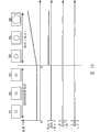
Figure 37 is the figure that illustrates according to an embodiment of the invention, constructed by parallel connection interframe memory portion the example of video features test section.
Embodiment
Then, will embodiments of the invention be described with reference to accompanying drawing.
Fig. 1 illustrates the figure of the structure of data recording/reproducing device 100 according to an embodiment of the invention.
As shown in the figure, data recording/reproducing device 100 comprises CPU (CPU) 1, RAM (random access memory) 2, operation input section 3, video features test section 4, digital tuner 5, IEEE1394 interface 6, Ethernet (registered trade mark)/WLAN (local area network (LAN)) interface 7, USB (USB) interface 8, memory card interface 9, HDD (hard disk drive) 10, CD drive 11, buffer controller 13, selector 14, demodulation multiplexer 15, AV (audio/video) decoder 16, OSD (showing on the screen) 17, video d/a (digital-to-analog) transducer 18 and audio D/A converter 19.
Under the control of CPU 1, digital tuner 5 receives the broadcast singal of broadcast program via the antenna (not shown) with digital broadcasting, and listens to, and the broadcast singal of the concrete channel of rectification.This broadcast singal is outputed to demodulation multiplexer 15 to be reproduced via selector 14, is recorded on the HDD 10 via buffer controller 13, or is recorded on the CD 12 that is inserted into CD drive 11.
IEEE 1394 interfaces 6 can be connected in the external equipment such as digital video camcorder.For example, with the same in the situation of the video content that is received broadcast program by digital tuner 5, the video content of being taken and being write down by digital video camcorder is reproduced, or is recorded on HDD 10 or the CD 12.
Ethernet (registered trade mark)/WLAN interface 7 is used to for example use Ethernet (registered trade mark) or WLAN to import the video content by PC or other data recording/reproducing devices record.Video content in this case also can be reproduced or recorded on HDD 10 or the CD 12.
Except be received as broadcast singal or from the various video contents of external equipment input; HDD10 records various programs, data etc. on the built-in hard disk; And when it reproduces, read these programs, data etc. from hard disk, with to buffer controller 13 dateouts.
CD drive 11 records video content etc. on the CD 12, and when it reproduces, reads video content etc., with to buffer controller 13 dateouts.CD 12 is for example DVD (digital universal disc), BD (Blu-ray disc) and CD (compact-disc).
OSD 17 generates the figure that will be displayed on the display (not shown) etc., and synthetic processing or transformation (switching) that the figure that generates etc. applies vision signal are handled.Afterwards, OSD 17 is to video d/a transducer 18 output processed video signals.Video d/a transducer 18 will convert analog signal to from digital signal by the vision signal that OSD 17 applies after the graphics process, obtaining NTSC (NTSC) signal, and the signal after the display (not shown) output conversion that is used to show.
Audio D/A converter 19 will convert analog signal to from digital signal from the audio signal of AV decoder 16 inputs, and the signal after the loud speaker (not shown) output conversion that is used for its reproduction.
Video features test section 4 is from vision signal before or the video signal detection video features after being decoded by AV decoder 16 of being decoded by AV decoder 16.Fig. 2 and 3 is figure of diagram video features.
Fig. 2 A illustrates and comprises scene S1-to S6 and when the video that begins on a left side from scene S1 or right-hand lay is taken when moving (shaking) video camera.Fig. 2 B illustrates and comprises the video that scene S1 takes when scene S1 begins to amplify to S6 and when video camera.In this embodiment, by such as the video camera work of shake, tilt (not shown) and convergent-divergent and the video features that causes is called as the camera operation characteristic.
Fig. 3 A illustrates the switching point fa place that provides between its scene scape S3 on the scene and the S4 is converted to S4 from scene S3 state.Fig. 3 B illustrates its scene like the state that fades out gradually scene S1 appears to the S3 order and another scene is faded in gradually as scene S4 appears to the S6 order.In this embodiment, the video features that when editor such as the video that comprises the video effect that switches and be fade-in fade-out, causes or be called as the video editing characteristic through the similitude (not shown) that is coupled between the scene that the scene of taking in a plurality of places causes.
Video features test section 4 is detected such as camera operation characteristic and video editing characteristic through the common signal treatment system that will describe after a while, and uses detected video features to carry out handling such as the video content that high bright field scape generates and chapters and sections generate.
Fig. 4 is each figure that the camera operation characteristic schematically is shown.
Fig. 4 A illustrates left and shakes.In this case, the object in the video moves on right-hand lay.
Fig. 4 B illustrates to the right and shakes.In this case, the object in the video moves on the direction leftward.
Fig. 4 C illustrates downward-sloping.In this case, the object in the video moves up.
Fig. 4 D illustrates and is inclined upwardly.In this case, the object in the video moves down.
Fig. 4 E shows amplification.In this case, the object in the video is enlarged.
Fig. 4 F shows and dwindles.In this case, the object in the video is retracted.
Fig. 5 is the figure that is schematically illustrated in the variable quantity of the image in the convergent-divergent.
In order to detect the camera operation characteristic in video content, be necessary that using piece to mate detects the motion vector in video content.But, as shown in Figure 4 because the amount of exercise of scaled images than the image after shaking or the amount of exercise of the image after tilting littler, so that its detection level also is regarded as is little.Therefore, when using piece coupling of the prior art single, possibly not detect convergent-divergent, the detection that therefore leads to errors.Therefore, this embodiment uses a plurality of combination to carry out the piece coupling.
At this, shown in the arrow d of Fig. 5, the variation of the image in convergent-divergent is the variation on radial direction (oblique line directions).Therefore, when its variable quantity of projection on X and Y direction, the variable quantity of being indicated respectively by arrow x and y is all less than in the radial direction original variable quantity.Therefore; Wrong detection in the piece coupling is regarded as; Wrong detection in the piece coupling of the combination of another piece that uses particular block and on X or Y direction, arrange uses particular block and the wrong detection in the piece coupling of the combination of another piece of arranging in the radial direction to be suppressed manyly.Therefore, in this embodiment, video features test section 4 is used in the combination of the piece of arranging in the radial direction and is carried out the piece coupling, and its concrete processing will be described after a while.
Mention that along band recent home videos video camera has been assembled so-called image shake correction function usually.But the correcting value of image shake correction function is restricted, and the video content of therefore being taken by the home videos video camera possibly comprise the picture of shake more or less very much.In addition, in fact, inventor of the present invention experimentally relatively with home videos video camera video of taking and the video of in the film studio, taking, such as broadcast program, and the vibration of finding the motion vector in two videos is measured, and difference is very big each other.
Fig. 6 is the figure that schematically illustrates based on the shake picture of experimental results.As shown in the figure, by shaking and tilt and the picture that causes randomly shaking in the frame unit.Therefore, can change through detecting the sequential behavior of shaking and tilting in the predetermined portions in the video content, be that the sequential behavior of motion vector changes the mobile shake that causes that detects by hand.
Therefore, can distinguish with the video content of broadcasted content record and the video content of taking with the home videos video camera through detecting the appearance of shaking picture or do not occur or its occurrence frequency, becoming.Hypothetical record/transcriber 100 storing therein various content of multimedia, therefore think that the video content that when for example organizing video content, is distinguished from each other is very effective.Therefore, in this embodiment, video features test section 4 is not only detected and is shaken, inclination and convergent-divergent, also detects the mobile shake that causes by hand, and as the camera operation characteristic, its concrete processing will be described after a while.
Fig. 7 is the calcspar that the structure of video features test section 4 schematically is shown.
As shown in the figure, video features test section 4 comprises image processing section 21,1-frame-interval memory portion 22,10-frame-interval memory portion 23,20-frame-interval memory portion 24,30-frame-interval memory portion 25, be used for the matching treatment part 26,28,30 and 32 of each memory portion, also be provided for being fade-in fade-out of each memory portion/hand-off process part 27,29,31 and 33, motion vector processing section 34, camera feature judgment part 36, be fade-in fade-out/switching judging part 35 and scene ID processing section 37.
Should note; The reason of in baseband bandwidth, handling is; The video content that consideration will be reproduced in data recording/reproducing device 100; Possibly coexist with the video content of various forms, such as VHS (video home system) formatted data and the 8-mm formatted data of digital record DV (digital video) formatted data except the mpeg format data, analog record, the video features that therefore in common signal treatment system as much as possible, carries out from these video contents extracts processing.
1-frame-interval memory portion 22,10-frame-interval memory portion 23,20-frame-interval memory portion 24 and 30-frame-interval memory portion 25 are stored in the image data section in the following scope: this scope has each frame at the interval of 1 frame, 10 frames, 20 frames and 30 frames to basic frame from the frame (after this being called basic frame) that has extracted basic block.Certainly, frame period is not limited to this.
Based on difference value after the coupling of importing respectively from matching treatment part 26,28,30 and 32; Be fade-in fade-out/hand-off process part 27,29,31 and 33 generates respectively and is fade-in fade-out/the handover evaluation value; And to being fade-in fade-out/switching judging part 35 these values of output, its detailed process will be described after a while.
Should be noted that to be fade-in fade-out/hand-off process part 27,29,31 and 33 can calculate respectively from the basic block of image processing section 21 input and difference value that obtain and that the piece matching treatment, use from the search blocks that interframe memory portion 22 to 25 is imported respectively.
Based on the motion vector amount that obtains owing to the piece matching treatment and import from matching treatment part 26,28,30 and 32 respectively; Motion vector processing section 34 estimate and home position between have the motion vector amount of position of the frame period of 30 frames or more as 40 frames; And the motion vector amount of estimating to camera feature judgment part 36 output, its detailed process will be described after a while.
Motion vector amount based on the estimation of 34 inputs from the motion vector processing section; The camera operation characteristic of shaking in the video content, inclination and convergent-divergent is judged in camera feature judgment part 36 through the multiple regression analysis of using the affine transformation model of describing after a while; And to CPU 1 output judged result, its detailed process will be described after a while.
Based on respectively from be fade-in fade-out/hand-off process part 27,29,31 and 33 the input be fade-in fade-out/the handover evaluation value; Be fade-in fade-out/the video editing characteristic of being fade-in fade-out or switching of switching judging part 35 judgements in video content, and to CPU 1 output judged result.
View data based on the retrieval frame of importing respectively from interframe memory portion 22 to 25; Between the vector that scene ID processing section 37 is scheduled to apart from computing; With similarity between judgment frame; Distribute each scene ID based on judged result to frame, and to CPU 1 output result, its detailed process will be described after a while.
Next, with describing so operation of the data recording/reproducing device 100 of structure.
Fig. 8 is the flow chart that the flow process of the processing of when data recording/reproducing device 100 detects video features, carrying out is shown.
As shown in the figure, the initial setting up (step 41) of the certification mark of each video features is at first carried out in video features test section 4.Certification mark is indicated respectively and is shaken, the camera operation characteristic of inclination, convergent-divergent and shake, and has detected the video editing characteristic of being fade-in fade-out and having switched from video content.The certification mark of representing video features respectively by Dpan, Dtilt, Dzoom, Dbure, Dfade and Dcut, and in initial setting up, its mark value is set to 0.
Subsequently, image processing section 21, interframe memory portion 22 to 25, matching treatment part 26,28,30 and 32 are used in video features test section 4, and the motion vector (step 42) in the 34 detection video contents of motion vector processing section.
Now, will specifically describe motion vector and detect processing.Fig. 9 illustrates the flow chart that motion vector detects the flow process of handling.
Mention along band, as stated, in motion vector detect to be handled, can be through search domain being set having in each predetermined frame retrieval frame at interval with basic frame, and carry out the piece matching treatment between basic frame and each search domain, detect motion vector.But when fast moving had been taken the video camera of video content, for example, oversize frame period possibly cause at this interval in the numerous appearance campaign of this video intermediate frequency, therefore reduced detection resolution performance and forbidding (disable) accurately motion vector detect.
In addition, when mobile camera lentamente, too short frame period causes the detected value of the detected motion vector at the interval excessively to reduce, and therefore also forbidding accurately in this case, motion vector detects.
Under the above-mentioned situation of fast moving video camera, possibly shift out search domain corresponding to the piece of basic block.But, can't judge between detection period corresponding to the piece of basic block whether in range of search or outside range of search.
Therefore, in this embodiment, video features test section 4 is based on the amount of exercise at the test point place in the piece coupling and the residual values of coupling estimates to retrieve accuracy.When being judged as when inaccurate, video features test section 4 does not use it to detect data, and only uses and detect data accurately, and the matched data that is based on other frame period places is estimated the motion vector amount at longer frame period place.Then, video features test section 4 uses the motion vector amount of estimating as the motion vector amount that will be used to detect video features.
As shown in Figure 9, video features test section 4 at first indicates the Counter Value m of the quantity that detects data segment accurately to be set to 0 (step 91).To describe Counter Value m in detail after a while.
Subsequently; Video features test section 4 is used from the basic frame of image processing section 21 inputs and is stored in the retrieval frame the interframe memory portion 22 to 25 respectively; Detect processing (step 92 is to 95) to carry out motion vector at 1-frame period, 10-frame period, 20-frame period and 30-frame period place by matching treatment part 26,28,30 and 32 respectively, its detailed process will be described after a while.
Next; Be based on the data of the motion vector that detects at each frame period place; The motion vector (step 96) that video features test section 4 uses motion vector processing section 34 to estimate at 40-frame period place; And to the data conduct last motion vector data (step 97) of camera feature judgment part 36 outputs about the motion vector of estimation, its detailed process will be described after a while.
Then, video features test section 4 judges whether all frames that constitute single video content to have been exported motion vector data, and the processing of repeating step 91 to 97 is up to all frames have been detected motion vector (step 98).
Figure 10 to 13 specifically illustrates in motion vector detect to be handled the flow chart that is in the processing of step 92 to 95 among Fig. 9 at each frame period respectively.At first, will be described in 1-frame period motion vector detection processing in the step 92.
Shown in figure 10, at first, image processing section 21 and matching treatment part 26 carry out basic frame and and basic frame have the piece matching treatment (step 921) between the retrieval frame of 1-frame period.
Now, will describe the piece matching treatment in detail.Figure 14 is the flow chart that the flow process of piece matching treatment is shown.
As shown in the figure, illustrated process part 21 at first is provided with reference picture zone and search domain (step 101) in basic frame.Figure 15 is the figure that the state that is provided with reference picture zone and search domain is shown.
As shown in the figure, matching treatment part 26 is provided with and is defined in the search domain 72 as the range of search of the motion vector in the basic frame 71 of original image (S), and is arranged on the reference picture zone 73 detection target zones as motion vector of search domain 72 inside.
Then, matching treatment part 26 is divided into for example 8 * 8=64 zone 74 with reference picture zone 73, and each central point of regional 74 is set as motion vector detection impact point Pn (n=0 to 63).
The size that should be noted that basic frame 71 is 720 * 480 (pixels) for example, but is not limited to this.In addition, original image (S) can be contraction (contracted) image of basic frame 71.For example; When basic frame 71 has size 720 * 480 (pixel); The image that have 1/4 the image (length on horizontal and vertical half the) of the size of original image (S), promptly has a size of 360 * 240 (pixels) is set to original image (S), and search domain 72 is set at image inside with reference picture zone 73.Therefore, can reduce the load on matching treatment part 26,28,30 and 32, and not be reduced in the accuracy in the piece matching treatment after a while.
Return with reference to Figure 14, the n that image processing section 21 motion vectors detect impact point Pn is set to 0, and basic block is set to the basis (step 102) about the piece matching treatment of P0.Figure 16 is the figure that the method that basic block is set is shown.
As shown in the figure, image processing section 21 is at first obtained the coordinate that detects impact point Pn (P0 in this example), and (xn, yn), the center of simultaneously basic frame 71 is as initial point O (0,0) (step 103).Subsequently, image processing section 21 is provided with predetermined value an (step 104).For example, this value an be the following basic frame that is provided with a side length 1/2.This value an for example is set to 4, but is not limited to this.
Then, shown in Figure 16 A, according to the function that is set to Fn (the x)=knx (kn=yn/xn) on basic frame 71, image processing section 21 uses settings an to calculate two coordinates (step 105) like minor function.
Pn1(xn-an,Fn(xn-an))
Pn2(xn+an,Fn(xn+an))
Subsequently, image processing section 21 is provided with the basic block Bn1 (step 106) that coordinate points Pn1 is the center, and basic block Bn1 is divided into s * s fritter bn1 (step 107).
Then, image processing section 21 is provided with the basic block Bn2 (step 108) that coordinate points Pn2 is the center, and basic block Bn2 is divided into s * s fritter bn2 (step 109).
Shown in Figure 16 B, when s=4, each of basic block Bn1 and Bn2 all is made up of to b15 fritter b0.In addition, shown in Figure 16 C, each of fritter bn1 and bn2 is corresponding to the for example mean value of four sections pixel datas.
At this, suppose that four sections pixel datas are respectively dn1, dn2, dn3 and dn4, each of fritter bn1 and bn2 can be regarded as 3 dimensional vector data Y, Cb and Cr.When respectively with suffix _ y, _ cb and _ when cr distributes its data component, for example, can explain the data component of fritter bn1 respectively by following expression formula.
bn1_y=(dn1_y+dn2_y+dn3_y+dn4_y)/4
bn1_cb=(dn1_cb+dn2_cb+dn3_cb+dn4_cb)/4
bn1_cr=(dn1_cr+dn2_cr+dn3_cr+dn4_cr)/4
When accomplishing being provided with of basic block Bn1 and Bn2 as stated, respectively by matching treatment part 26,28,30 and 32 beginnings piece matching treatment at 1-frame period, 10-frame period, 20-frame period and 30-frame period place.Should be appreciated that, after this, with only describing the piece matching treatment of carrying out at 1-frame period place by matching treatment part 26, and its handle with carry out at each frame period place by matching treatment part 28,30 and 32 the same.
Based on the fritter bn1 of basic block Bn1 and the fritter bn2 of basic block Bn2, matching treatment part 26 is carried out piece matching treatment (step 110).Figure 17 is the figure that the state that carries out the piece matching treatment is shown.Figure 17 A is illustrated in basic block Bn1 and the Bn2 (after this, two basic blocks will be collectively referred to as basic block Bn) in the basic frame 71, and Figure 17 B is illustrated in search blocks Bm1 and Bm2 (after this, two search blocks also will be referred to as search blocks Bm) in the retrieval frame 75.
As shown in the figure; Matching treatment part 26 is extracted the basic block Bn of two settings from basic frame 71; And carry out the position that pattern matched has moved in retrieval frame 75 with the piece that detects corresponding to basic block Bn, have predetermined frame interval (1-frame period in this example) between wherein basic frame 71 and the retrieval frame 75.Particularly; Matching treatment part 26 is extracted the searched targets piece with shape and size identical with basic block Bn in the search domain 72 of retrieval frame 75; And when next pixel ground mobile search object block; Detect the position Pm of search blocks Bm, the vector distance of each data component Y, Cb and the Cr of each fritter bn of basic block Bn becomes minimum herein.The searched targets piece becomes motion vector MV from the amount of exercise Vn and the direction of motion of coordinate points Pn Pm to its detection position of basic frame 71.In addition, matching treatment part 26 is also calculated residual values after the coupling between basic block Bn and the search blocks Bm, and amount of exercise.
When accomplishing when detecting about the motion vector that detects impact point Pn, matching treatment part 26 increases progressively 1 (step 112) with n, and repeats above-mentioned processing and become nmax or more (step 113) up to n.In this embodiment, nmax is 63.
Through above-mentioned processing, basic block Bn1 and Bn2 are set at from the center of basic frame 71 in the radial direction.In other words, basic block Bn1 and Bn2 are provided so that and are centered at the point that is positioned on the half line (half line) that begins from the center of basic frame 71 respectively.Through so piece being set in the radial direction, can be increased in detection accuracy in the special motion vector in convergent-divergent in other camera operation characteristics as stated significantly.In addition; Be used for the piece matching treatment through the combination of using two pieces; Situation than single of the use of of the prior art matching treatment; Can not only increase the accuracy of the motion vector of detection in convergent-divergent, can also increase detection on X and Y direction, promptly shake and tilt in the accuracy of motion vector.
At this, as stated, in this embodiment, when judging that detected motion vector is inaccurate, video features test section 4 does not use it to detect data, to be increased in the accuracy that detects in the motion vector.Then, set forth in detail, return Figure 10 and will describe step 922 and the processing of step thereafter like the description of handling.
As stated, except being provided for retrieving the search domain 72 of motion vector, matching treatment part 26 also is provided for being increased in another range of search that detects the accuracy in the motion vector.This range of search be for example from the X that detects impact point Pn and Y both direction ± 8.In addition, matching treatment part 26 predetermined threshold Eth are set to residual values after the coupling between basic block Bn and the search blocks Bm.Particularly; When criterion is set so as detection position Pm and the distance that detects impact point Pn+or-should be on the direction than 8 pixels many and coupling when afterwards residual values should be less than predetermined threshold Eth, matching treatment part 26 do not use do not satisfy criterion, as the detection data of inaccurate data.The numerical value of range of search is not limited to 8 certainly.
At this, the X (level) during 1-frame period motion vector detects is set to V1xn and V1yn respectively with the amount of exercise on Y (vertical) direction, and residual values is set to E1n.
Shown in figure 10, matching treatment part 26 detects amount of exercise V1xn and V1yn and the residual values E1n (step 922) that is detected at 1-frame period place by the piece matching treatment.Then, matching treatment part 26 judges whether to satisfy based on criterion:
|V1xn|<8,
| V1yn|<8, and
E1n<Eth (step 923 and 924), when these values satisfied criterion, matching treatment part 26 suitable weighted factor K1 were set to 1, and will indicate the Counter Value m of the quantity that detects data segment accurately to increase progressively 1 (step 925).In addition-and the aspect, when these values did not satisfy criterion, matching treatment part 26 K1 were set to 0 (step 926).Then, matching treatment part 26 is to motion vector processing section 34 output weighted factor K1 sum counter value m and detected amount of exercise V1xn and V1yn and residual values E1n.
Next, detect the processing of carrying out after the processing 10-interframe spacer block matching treatment with being described in motion vector.At this, the X (level) during 10-frame period motion vector detects is set to V10xn and V10yn respectively with the amount of exercise on Y (vertical) direction, and residual values is set to E10n.
Shown in figure 11, matching treatment part 28 detects amount of exercise V10xn and V10yn and the residual values E10n (step 932) that is detected at 10-frame period place by the piece matching treatment.Then, matching treatment part 28 judges whether to satisfy based on criterion:
|V10xn|<8,
| V10yn|<8, and
E10n<Eth (step 933 and 934).When these values satisfied criterion, matching treatment part 28 suitable weighted factor K10 were set to 1, and will indicate the Counter Value m of the quantity that detects data segment accurately to increase progressively 1 (step 935).On the other hand, when these values did not satisfy criterion, matching treatment part 28 K10 were set to 0 (step 936).Then, matching treatment part 28 is to motion vector processing section 34 output weighted factor K10 sum counter value m and detected amount of exercise V10xn and V10yn and residual values E10n.
Next, detect the processing that processing is carried out with being described in motion vector after 20-interframe spacer block matching treatment.At this, the X (level) during 20-frame period motion vector detects is set to V20xn and V20yn respectively with the amount of exercise on Y (vertical) direction, and residual values is set to E20n.
Shown in figure 12, matching treatment part 30 detects amount of exercise V20xn and V20yn and the residual values E20n (step 942) that is detected at 20-frame period place by the piece matching treatment.Then, matching treatment part 30 judges whether to satisfy based on criterion:
|V20xn|<8,
| V20yn|<8, and
E20n<Eth (step 943 and 944).When these values satisfied criterion, matching treatment part 30 suitable weighted factor K20 were set to 1, and will indicate the Counter Value m of the quantity that detects data segment accurately to increase progressively 1 (step 945).On the other hand, when these values did not satisfy criterion, matching treatment part 30 K20 were set to 0 (step 946).Then, matching treatment part 30 is to motion vector processing section 34 output weighted factor K20 sum counter value m and detected amount of exercise V20xn and V20yn and residual values E20n.
Next, detect the processing that processing is carried out with being described in motion vector after 30-interframe spacer block matching treatment.At this, the X (level) during 30-frame period motion vector detects is set to V30xn and V30yn respectively with the amount of exercise on Y (vertical) direction, and residual values is set to E30n.
Shown in figure 13, matching treatment part 32 detects amount of exercise V30xn and V30yn and the residual values E30n (step 952) that is detected at 30-frame period place by the piece matching treatment.Then, matching treatment part 32 judges whether to satisfy based on criterion:
|V30xn|<8,
| V30yn|<8, and
E30n<Eth (step 953 and 954).When these values satisfied criterion, matching treatment part 32 suitable weighted factor K30 were set to 1, and will indicate the Counter Value m of the quantity that detects data segment accurately to increase progressively 1 (step 955).On the other hand, when these values did not satisfy criterion, matching treatment part 32 K30 were set to 0 (step 956).Then, matching treatment part 32 is to motion vector processing section 34 output weighted factor K30 sum counter value m and detected amount of exercise V30xn and V30yn and residual values E30n.
Next, the motion vector estimation that is described in the step 96 in Fig. 9 of being undertaken by motion vector processing section 34 is handled.Figure 18 is the flow chart that the flow process of motion vector estimation processing is shown.At this, in order to estimate motion vector, detect frame period and amount of exercise based on each at 40-frame period place, calculate favourable gradient.Figure 19 is the figure that this gradient is shown.
Shown in figure 18, summation is at first asked to the enter counter value m that imports from matching treatment part 26,28,30 and 32 respectively in motion vector processing section 34, whether is equal to or greater than 1 (step 961) to judge this summation.When the summation of Counter Value is equal to or greater than 1 (being), the gradient (step 962) that calculate at the motion vector at each frame period place motion vector processing section 34.
Now, will at first be described below situation:, calculate the gradient T1xn of 1-frame period motion vector based on interval L1t (1-frame period) and amount of exercise V1xn.
Detect the pts that frame period L1t the is basic frame 71 (ratio of the pts time interval p1t of the retrieval frame 75 of 1 frame after the basic frame 71 of prompt time stamp (Presentation TimeStamp) time interval p0 and conduct.Therefore, can use following expression formula to calculate and detect frame period L1t.
L1t=p1t/p0
This be because, owing to frame rate possibly depend on that video content differs from one another, thus when compute gradient the normalization 1-frame period time.
Therefore, can use following expression formula to calculate about the momental gradient on directions X.
T1xn=V1xn/L1t
In addition, can use following expression formula to calculate about the momental gradient on the Y direction.
T1yn=V1yn/L1t
Similarly, will be described below situation,, calculate the gradient T10xn of 10-frame period motion vector based on interval L10t (10-frame period) and amount of exercise V10xn.
Detect frame period L10t and be the pts time interval p0 of basic frame 71 and ratio as the pts time interval p10t of the retrieval frame 75 of 10 frames after the basic frame 71.Therefore, can use following expression formula to calculate and detect frame period L10t.
L10t=p10t/p0
Therefore, can use following expression formula to calculate about the momental gradient on directions X.
T10xn=V10xn/L10t
In addition, can use following expression formula to calculate about the momental gradient on the Y direction.
T10yn=V10yn/L10t
Similarly, will be described below situation,, calculate the gradient T20xn of 20-frame period motion vector based on interval L20t (20-frame period) and amount of exercise V20xn.
Detect frame period L20t and be the pts time interval p0 of basic frame 71 and ratio as the pts time interval p20t of the retrieval frame 75 of 20 frames after the basic frame 71.Therefore, can use following expression formula to calculate and detect frame period L20t.
L20t=p20t/p0
Therefore, can use following expression formula to calculate about the momental gradient on directions X.
T20xn=V20xn/L20t
In addition, can use following expression formula to calculate about the momental gradient on the Y direction.
T20yn=V20yn/L20t
Similarly, will be described below situation,, calculate the gradient T30xn of 30-frame period motion vector based on interval L30t (30-frame period) and amount of exercise V30xn.
Detect frame period L30t and be the pts time interval p0 of basic frame 71 and ratio as the pts time interval p30t of the retrieval frame 75 of 30 frames after the basic frame 71.Therefore, can use following expression formula to calculate and detect frame period L30t.
L30t=p30t/p0
Therefore, can use following expression formula to calculate about the momental gradient on directions X.
T30xn=V30xn/L30t
In addition, can use following expression formula to calculate about the momental gradient on the Y direction.
T30yn=V30yn/L30t
Therefore, when the summation of weighted factor (K1+K10+K20+K30) greater than 0 the time, can use following expression formula to come to calculate respectively at average gradient Tavex (n) on the directions X and the Tavey on the Y direction (n).
Tavex(n)=(K1×T1xn+K10×T10xn+K20×T20xn+K30×T30xn)/(K1+K10+K20+K30)
Tavey(n)=(K1×T1yn+K10×T10yn+K20×T20yn+K30×T30yn)/(K1+K10+K20+K30)
In addition, when (K1+K10+K20+K30) is 0, can use following expression formula to come to calculate respectively Tavex (n) and Tavey (n).
Tavex(n)=0
Tavey(n)=0
Next, use the average gradient that is calculated, the motion vector (step 963) at 40-frame period place is suitably estimated in motion vector processing section 34.Particularly, motion vector processing section 34 can be multiply by frame period with the average gradient that is calculated and so calculated the amount of exercise that is equal to shown in figure 19.In other words, can use following expression formula for X and Y direction calculating estimated motion vector (estimated amount of exercise) at 40-frame period place.
40×Tavex(n)
40×Tavey(n)
Should be noted that when compute gradient, at the straight line (y=ax) of all frame period desired through initial point shown in figure 19.Therefore, the calculated value of each gradient is an approximation.
The motion vector (step 97 of Fig. 9) that impact point Pn place obtains is being detected to the estimated motion vector conduct of camera feature judgment part 36 outputs in motion vector processing section 34.In addition, when the summation of Counter Value m was 0 (denying) in step 961, motion vector processing section 34 motion vectors were set to 0 (step 964), and 36 outputs should value (step 97 of Fig. 9) to the camera feature judgment part., the multiple regression analysis of describing after a while uses the motion vector of being exported in handling.
As stated, because criterion is provided so that the detection data that do not satisfy standard, is that inaccurate detection data are not used to detect motion vector, therefore can be increased in the accuracy that detects in the motion vector.In addition; The detection data of the motion vector through being based on each frame period place are estimated detecting the motion vector at the longer frame period place of frame periods than other; Can expand the scope (dynamic range) that detects data; Therefore detect data conditions than bi-directional scaling (scaling) only, improved the data resolution performance.
Return with reference to figure 8, video features test section 4 is based on the motion vector data of 34 outputs from the motion vector processing section, and (step 43) handled in the multiple regression analysis of carrying out being undertaken by camera feature judgment part 36, and calculates affine coefficients (step 44).Now, use description in multiple regression analysis is handled, calculate the affine transformation model of affine coefficients.
Figure 20 illustrates the affine transformation model.This affine transformation model is used to the description of parallel motion, expansion/contraction and the rotation of 3 dimension objects, as the coordinate transform processing of using matrix.Because shake, the camera operation characteristic of inclination and convergent-divergent is regarded as parallel motion and the expansion/contraction of object in basic frame 71, therefore, can use the affine transformation model to describe the camera operation characteristic.
At this, when frame period is little in video content, suppose that anglec of rotation θ is little about the rotation characteristic, can carry out following approximate processing:
sinθ≈θ
Therefore, the model of conversion affine transformation as illustrated in fig. 20.In addition, can detect the camera operation characteristic based on the motion vector calculation coefficient that is detected through using the affine transformation model.Particularly, predetermined threshold Pth, Tth and Zth can be provided for respectively shaking, inclination and convergent-divergent, and can it be compared with the affine coefficients of handling from the motion vector that is detected, with each camera operation characteristic of detection like this.
Figure 21 illustrates the processing that is used for calculating through multiple regression analysis affine coefficients.As shown in the figure; Explanatory variable is the xy coordinate (xn at the detection impact point Pn place in basic frame 71; Xy) and the variable that is illustrated (target variable (objective variable)) be xy coordinate (xm at the Pm place, motion vector detection position of retrieval in the frame 75; Ym), camera feature judgment part 36 through carry out multiple regression analysis handle calculate respectively shake, FACTOR P x, Py and the Zx (step 44) of inclination and convergent-divergent.
Return with reference to figure 8, camera feature judgment part 36 is imported from the affine coefficients of being calculated and is shaken FACTOR P x (step 45).Then, camera feature judgment part 36 judges that whether Px is greater than threshold value Pth (step 46).As Px during greater than Pth (being), camera feature judgment part 36 is shaken certification mark Dpan and is set to 1 (step 47), and when being equal to or less than Pth (denying), shaking certification mark Dpan and be set to 0 (step 48).
Subsequently, inclination FACTOR P y (step 49) is imported in camera feature judgment part 36 from the affine coefficients of being calculated.Then, camera feature judgment part 36 judges that whether Py is greater than threshold value Tth (step 50).As Py during greater than Tth (being), camera feature judgment part 36 tilt detection mark Dtilt are set to 1 (step 51), and when being equal to or less than Tth (denying), tilt detection mark Dtilt is set to 0 (step 52).
Next, zoom factor Zx and Zy (step 53) are imported in camera feature judgment part 36 from the affine coefficients of being calculated.Then, camera feature judgment part 36 judges that whether Zx or Zy are greater than threshold value Zth (step 54).When Zx and Zy at least-individual during greater than Zth (being), camera feature judgment part 36 convergent-divergent certification mark Dzoom are set to 1 (step 55), and when being equal to or less than Tth (denying), convergent-divergent certification mark Dzoom is set to 0 (step 56).
Should be noted that about shake, the camera operation characteristic of inclination and convergent-divergent, camera feature judgment part 36 can detect with distinguishing and shake left/shake to the right, be tilted to the left/be tilted to the right and amplify/dwindle in each.The positive and negative mark of each affine coefficients easily distinguishes by reference.
Subsequently, 36 pairs of camera feature judgment parts shake FACTOR P x and inclination FACTOR P y carries out Time-Series analysis, with to judging (step 57) by the mobile shake that causes of hand.Figure 22 is the figure that the shake judgment processing is shown.
Shown in figure 22; Camera feature judgment part 36 can based on for each predetermined portions in the video content (t0 to t1, t1 to t2, t2 to t3 and t3 to t4) number of times that the variation (variance) of shaking FACTOR P x and inclination FACTOR P y of having calculated from affine coefficients and Px or Py and the mean value level each predetermined portions are intersected, judge the mobile shake that causes by hand.Each predetermined portions is set to for example about 0.5 second to 5 seconds time span.
For example, part t0 in the drawings is in t1, and Px or Py and mean value level 12 are intersected inferior.Camera feature judgment part 36 is judged and whether is intersected variance that whether number of times surpass Px or Py in threshold value Thcr and each predetermined portions greater than predetermined threshold Thv (step 58).
At this; When the quantity of the data segment of Px that representes each predetermined portions by N and Py; Represent data segment by Px (n) and Px (y) respectively; And represent the mean value of those data segments respectively by Pxave and Pyave, and can use following expression formula to come to calculate respectively variance Pxvari and the Pyvari of Px and Py.
Pxvari=(1/N)∑((Pxave-Px(n))×(Pxave-Px(n)))
Pyvari=(1/N)∑((Pyave-Py(n))×(Pyave-Py(n)))
When intersecting in number of times and the variance any during greater than each threshold value (being), camera feature judgment part 36 judges that the picture of predetermined portions is to shake picture, and shakes certification mark Dbure and be set to 1 (step 59).When intersecting at least one of number of times and variance when being equal to or less than corresponding threshold (denying), camera feature judgment part 36 is shaken certification mark Dbure and is set to 0 (step 60).
Next, be fade-in fade-out and the change detection processing in video features test section 4.
At first, with describing by being fade-in fade-out/processing that hand-off process part 27,29,31 and 33 is carried out.
Be fade-in fade-out/hand-off process part 27,29,31 and 33 is respectively from matching treatment part 26,28,30 and 32 input coupling back residual values E1n, E10n, E20n and E30n, and to being fade-in fade-out/the estimated value (step 61) of being fade-in fade-out/switching that 35 outputs of switching judging part generate based on those residual values.
At this, when each representes residual values by En (n=0 to 63), can use following expression formula to calculate the estimated value H that is fade-in fade-out/switches.
Therefore; Be fade-in fade-out/hand-off process part 27,29,31 and 33 is respectively from matching treatment part 26,28,30 and 32 input residual values E1n, E10n, E20n and E30n; Arrive 63 up to n; Promptly detect the residual values of impact point P0, and calculate its summation respectively to P63 up to all that imported for basic frame 71.
Figure 23 and 24 is that each is illustrated in and is fade-in fade-out/result of calculation of handover evaluation value and for the figure of the relation between the passage of the frame of each frame period.Figure 23 is the figure that has comprised the situation of switching point, and Figure 24 is the figure that has comprised the situation of being fade-in fade-out.
Based on being fade-in fade-out shown in Figure 23 and 24/handover evaluation value, be fade-in fade-out/switching judging part 35 is fade-in fade-out/switching judging (step 62).Particularly; When the change in being fade-in fade-out of the passage that is being accompanied by frame/handover evaluation value is precipitous (in step 63 for being); Be fade-in fade-out/switching judging part 35 is judged this change as switching, and change detection mark Dcut is set to 1 (step 65).On the other hand; When along with the change in being fade-in fade-out of the passage of frame/handover evaluation value being (in step 64 for being) progressively; Be fade-in fade-out/this changes conduct of switching judging part 35 judgements is fade-in fade-out, and the certification mark Dfade that is fade-in fade-out is set to 1 (step 66).In the time can't detecting any one (in step 64 for not), be fade-in fade-out/switching judging part 35 change detection mark Dcut are set to 0 (step 67) with the certification mark Dfade that is fade-in fade-out.
Particularly, be fade-in fade-out/switching judging part 35 analyzes the 1-frame periods and be fade-in fade-out/change in the handover evaluation value, and when the peak feature shown in the figure a that detects Figure 23, judge that its peak point is a switching point.
In addition; When not detecting peak feature; Shown in figure 24, be fade-in fade-out/switching judging part 35 calculates at 1-frame period (poor Va, the 10-frame period that be fade-in fade-out assessed value and being fade-in fade-out of locating at 10-frame period (figure b) that figure a) locates obtains between the assessed value poor Vc that is fade-in fade-out and obtains between the assessed value that assessed value and the poor Vb that obtains between the assessed value being fade-in fade-out of locating of 20-frame period (scheming c) and 20-frame period are fade-in fade-out assessed value and are located at 30-frame period (scheming d) that is fade-in fade-out at the t place at the fixed time.
Therefore under the situation of being fade-in fade-out shown in Figure 24, because video progressively changes, be fade-in fade-out/the change amount of handover evaluation value depends on its frame period and differs from one another.Therefore, all values of Va, Vb and Vc is expressed as approaching against each other positive significantly.On the other hand, under the situation of switching shown in Figure 23, Va, Vb and Vc can all be different greatly each other negative values.Therefore, be fade-in fade-out/switching judging part 35 can detect and be fade-in fade-out through analyzing Va, Vb and Vc.
Should note; Except mating the residual values of back from matching treatment part 26,28,30 and 32 inputs respectively; As stated; Be fade-in fade-out/hand-off process part 27,29,31 and 33 can use individually from the basic block Bn of image processing section 21 input and respectively from 22 to 25 inputs of interframe memory portion and be used to the search blocks Bm the piece matching treatment, calculate and be fade-in fade-out/the handover evaluation value.Particularly; Be fade-in fade-out/hand-off process part 27,29,31 and 33 detects impact point Pn for each; For every segment data about Y, Cb and Cr; Detection poor between basic block Bn and search blocks Bm, and calculate the summation that differs from for detecting impact point P0 to P63 respectively, as being fade-in fade-out/the handover evaluation value.Data splitting through relatively basic block Bn1 and Bn2 and the data splitting of search blocks Bm1 and Bm2 calculate in this case poor.
In addition; Except the search blocks Bm that uses in the piece matching treatment retrieval back (moving the back); Be fade-in fade-out/hand-off process part 27,29,31 and 33 can detect impact point Pn for each, calculates poor between basic block Bn and the searched targets piece that arranges the position identical with basic block Bn in the retrieval frame.But, use aforesaid coupling back residual values need being fade-in fade-out naturally/less load on the hand-off process part 27,29,31 and 33.
Next, video features test section 4 is carried out scene ID and is handled (step 68), and its detailed process will be described below.Figure 25 is the figure that the structure of scene ID processing section 37 is shown.
As shown in the figure, scene ID processing section 37 comprises that data storage 81, vector distance calculating section 82, ID generate part 83 and ID memory 84.
Vector distance calculating section 82 sequentially carries out in the input block data of single frame and is respectively stored in the vector distance computing between the blocks of data section of other frames of storage area V0 in the Vn, and judges the blocks of data with minimum vector distance.In other words, vector distance calculating section 82 comes the similarity of judgment frame based on blocks of data, and confirms the frame similar in appearance to this frame.
Based on the result of compute vector distance, ID generates part 83 generations and is used for being respectively stored in the scene ID of storage area V0 to the blocks of data section of Vn.ID memory 84 is sequentially stored the scene ID that is generated at storage area Id0 respectively in Idn.
The storage area V0 of data storage 81 corresponds to each other respectively to Idn to the storage area Id0 of Vn and ID memory 84.For example, in the drawings, the blocks of data of judging input when vector distance calculating section 82 is similar in appearance to the blocks of data that is stored among the storage area V5, generate be stored in storage area Id5 in the identical ID of ID, and distribute the ID that is generated for the blocks of data of input.The blocks of data of input is stored among the storage area V0 of data storage 81, and the ID that is generated is stored among the storage area Id0 of ID memory 84.At this moment, the blocks of data that before generating ID, has been stored among the storage area V0 is moved to storage area V1, and the blocks of data that has been stored among the storage area V1 is moved among the storage area V2.In addition, the ID that before generating ID, has been stored among the storage area Id0 of ID memory 84 is moved to storage area Id1, and the ID that has been stored among the storage area Id1 is moved among the storage area Id2.As stated, when generating ID, move the data segment of in each storage area of data storage 81 and ID memory 84, storing at every turn.ID generates part 83 and sequentially exports the ID that is generated to CPU1.
When judging that by the vector distance computing this blocks of data and blocks of data in any storage area that is stored in data storage 81 do not have similitude, distribute new ID to it.In addition, when all storage areas of data storage 81 and ID memory 84 become full, begin sequentially to delete the data segment of being stored from the oldest data.
Should be noted that data storage 81 and ID memory 84 can be provided the memory devices as physical separation, maybe can be provided as the single memory equipment of being divided as each memory.
In addition, except carrying out the processing of 1-frame period, can use 10-frame-interval memory portion 23,20-frame-interval memory portion 24 and 30-frame-interval memory portion 25 to carry out ID at 10-frame period, 20-frame period and 30-frame period place respectively and handle.Therefore, can save the memory capacity of data storage 81 and ID memory 84, and reduce the load on vector distance calculating section 82 and ID generation part 83.
Figure 26 illustrates by ID to handle the scene ID of output and the figure of the relation between the frame number.
As the figure (a) and (b) of Figure 26 with (c) shown in, for example, can see, give successive frame and between have predetermined frame frame at interval and distribute identical scene ID.The frame that has been assigned with identical scene ID is regarded as similar scene, with the reproduction of the high bright field scape that therefore enables for example to describe after a while etc.
Figure 27 be illustrate by camera feature judgment part 36 be fade-in fade-out/table of the judged result of each video features that switching judging part 35 obtains.CPU 1 control is equal to the data of this table with storage in for example RAM 2 or HDD 10.
This is expressed; Certification mark Dpan, Dtilt, Dzoom, Dbure, Dfade and Dcut about each video features are set to 1, and from detect the target video content detection shake, inclination, convergent-divergent, the video features shaking, be fade-in fade-out and switch.CPU 1 is for each video content creation judged result table.
As stated, video features test section 4 can shake through using public signal processing system to detect, the camera operation characteristic of inclination, convergent-divergent and shake and be fade-in fade-out, the video editing characteristic of switching and similar scene.Particularly; Based on about the data of the basic block Bn that extracts by image processing section 21 with about being respectively stored in the data of the search blocks Bm in the interframe memory portion 22 to 25; Video features test section 4 is detected at the motion vector between each frame through the piece matching treatment of being undertaken by matching treatment part 26,28,30 and 32, and judges the camera operation characteristic through motion vector processing section 34 and camera feature judgment part 36.Simultaneously; Be based on use in the piece matching treatment about the data of basic block Bn with about the data of search blocks Bm; Video features test section 4 through be fade-in fade-out/hand-off process part 29 generates and is fade-in fade-out/the handover evaluation value; And through be fade-in fade-out/switching judging part 35 analyzes this and is fade-in fade-out/the handover evaluation value, thereby detect the video editing characteristic of being fade-in fade-out and switching.In addition, based on the basic block Bn and the search blocks Bm that are respectively stored in the interframe memory portion 22 to 25, similar scene is detected in scene ID processing section 37.Therefore, according to this embodiment, can easily be configured to detect the system of various video features with low cost, and can improve detection efficiency.
In addition, can distinguish video content that writes down with broadcasted content and the video content of taking by above-mentioned home videos video camera through from the camera operation characteristic, detecting the mobile shake that causes, becoming by hand.
Next, with describing as stated the combination of video features that has detected the video content of video features from it.
Figure 28 is the figure that the scene combination partly of each video features that constitutes video content is shown.
Video content partly is made up of several scenes.Occurrence scene changes between a scene part and next scene part.Be fade-in fade-out or switch and cause scene change by what detect.Substantially, video content is made up of similar image (frame) part and image (frame) part that comprises the camera operation characteristic that is detected.The part that similar image section is made up of the identical frame of its ID that is detected.In addition, also there is the rare video content that only constitutes and do not comprise similar image section by the camera operation characteristic.
Figure 28 A illustrates the situation that video content only is made up of dissimilar image section.
Figure 28 B illustrates the situation that video content is made up of similar image section and amplifier section.
Figure 28 C illustrate video content by similar image section with dwindle the situation that part constitutes.
Figure 28 D illustrates video content by similar image section with shake the situation that part constitutes left.
Figure 28 E illustrates the situation that video content is made up of similar image section and downward-sloping part.
Figure 28 F illustrate video content by similar image section with comprise left shake, situation that amplification and downward-sloping part constitute.
Figure 29 be illustrated under the situation about constituting by similar image section and dissimilar image section based on the situation shown in Figure 28 A, video content, the figure of the detection characteristic of the scene ID of each video features and each camera operation characteristic.
As shown in the figure, part t0-t1 is the similar image section with same scene ID.Part t1-t2 is the dissimilar image section that comprises different scene ID, and the value of ID becomes big towards t2.Part t2-t3 is similar image section, but has the image pictures different with part t0-t1, therefore has different scene ID.From t3 and part afterwards is the similar image section that has with the image of the image similarity of part t0-t1, and therefore has the scene ID identical with part t0-t1.
Therefore in this case, do not detect the camera operation characteristic for all parts, each coefficient through shaking of analyzing that affine coefficients obtains, inclination and convergent-divergent becomes 0, or its absolute value becomes predetermined threshold or lower.
Figure 30 is the figure of detection characteristic that is illustrated in scene ID and each camera operation characteristic of each video features under the situation of Figure 28 B.
As shown in the figure, part t0-t1 is the similar image section with same scene ID.T1 and part afterwards are the amplifier sections with different scene ID, have wherein detected amplification coefficient.
Figure 31 is the figure of detection characteristic that is illustrated in scene ID and each camera operation characteristic of each video features under the situation of Figure 28 C.
As shown in the figure, part t0-t1 is the similar image section with same scene ID.T1 and part afterwards are the parts of dwindling with different scene ID, have wherein detected coefficient of reduction.
Figure 32 is the figure of detection characteristic that is illustrated in scene ID and each camera operation characteristic of each video features under the situation of Figure 28 D.
As shown in the figure, part t0-t1 is the similar image section with same scene ID.T1 and part afterwards be have a different scene ID shake part left, wherein detected and shaken coefficient left.
Figure 33 is the figure of detection characteristic that is illustrated in scene ID and each camera operation characteristic of each video features under the situation of Figure 28 E.
As shown in the figure, part t0-t1 is the similar image section with same scene ID.T1 and part afterwards are the downward-sloping parts with different scene ID, have wherein detected downward-sloping coefficient.
Figure 34 is the figure of detection characteristic that is illustrated in scene ID and each camera operation characteristic of each video features under the situation of Figure 28 F.
As shown in the figure, part t0-t1 is the similar image section with same scene ID.T1 and part afterwards are wherein to have detected amplification simultaneously, shake part with downward-sloping camera operation characteristic left, and this part has different scene ID.In this part, detected amplification, shaken and downward-sloping coefficient left.
As stated, by video editing characteristic and camera operation characteristic that the common signal treatment system detects, becoming to be organized in the scene part in the video content through combination.
Next, the example application of using the video features that is detected is described.
For example, the part that has wherein detected the camera operation characteristic can be assumed to the scene part of the shooting that photographer more payes attention to.Therefore, data recording/reproducing device 100 can extract from video content and therefore reproduce this scene from its scene that has detected the camera operation characteristic as high bright field scape.
Figure 35 is the figure that the example of high bright field scape reproduction processes is shown.In the drawings, adopt the convergent-divergent part as an example, but set up equally for shaking with sloping portion.
As shown in the figure; For example; When from the camera feature judgment part 36 the input zoom features detection the time; CPU 1 extract a plurality of detected convergent-divergents parts (frame c, d, k and l) and before each detected part with afterwards predetermined portions (frame b, e, j and m), and these parts are synthesized the reproducible part with " high bright reproduction mode ".At this, the reason of adding before each convergent-divergent part with afterwards these parts is, because only can't grasp the concrete scene as the reason of convergent-divergent from the convergent-divergent part, therefore is necessary to be provided with predetermined (margin) more than needed.
For example, about being recorded in the video content on the HDD 10, CPU 1 generates high bright field scape as new content.Then; For example; About be presented at the video content in the contents list on the display in response to user's request, CPU 1 carries out and allows the user for example to select all application of reproduction mode and high bright reproduction mode via operation input section 3, therefore to reproduce this content.
In addition, substitute use separately shake, the camera operation characteristic of inclination and convergent-divergent each, COU 1 can also be provided with high bright reproduction mode through making up a plurality of characteristics.Figure 36 is the figure that is illustrated in the example of high bright field scape reproduction in this case.
As shown in the figure, give shaken, each camera operation characteristic of inclination and convergent-divergent is provided with priority, and is created on three different in the recovery time high bright field scapes.
In other words, CPU 1 only extracts convergent-divergent part as high bright field scape in the bright reproduction mode 1 of height, so that the high bright field scape of minimum was provided to the user in 1 short time as far as possible.
In addition, CPU 1 partly adds to each convergent-divergent in the bright reproduction mode 2 of height and shakes part, though so that the recovery time is elongated slightly, with more detailed form high bright field scape is provided.
Then, CPU 1 in the bright reproduction mode 3 of height to each convergent-divergent part with shake part and add sloping portion, though, high bright field scape is provided with more detailed form so that the recovery time is elongated extraly.
During high bright reproduction mode in chosen content tabulation, CPU 1 makes each pattern of selecting simultaneously.
Through above-mentioned processing, detected shake, the camera operation characteristic of inclination and convergent-divergent can be used to reproduce high bright field scape effectively, therefore strengthened user's convenience.
In addition, the jitter feature in the camera operation characteristic can be used to the aforesaid video content that is distinguished from each other.
For example, whether Dbure is 1 based on the shake certification mark, and CPU 1 distributes different attributes for the video content that is recorded on HDD 10 grades, and these video contents are categorized as two types.Therefore, for example, when the user used operation input section 3 to come the demonstration of request content tabulation, CPU 1 can be so that come displaying content list for each class.In addition, when the user search content, CPU 1 can also make and select such as the retrieval inquiry.Therefore, because the range of search of video content is dwindled, therefore can alleviate the load of retrieval process, and can increase its speed.
In addition, in the video editing characteristic be fade-in fade-out with handoff features can be used in video content, insert chapters and sections.In other words, for example, be fade-in fade-out and when switching, switching point place in the video content of CPU 1 on being recorded in HDD 10 grades or the midpoint between beginning of being fade-in fade-out and the end point are inserted chapters and sections when detecting.Therefore, CPU 1 can jump to the desired scene of user apace, and reproduces this scene.
The present invention is not limited to the foregoing description, and certainly under the situation that does not break away from spirit of the present invention, carries out various modifications.
In Fig. 7 of the foregoing description, construct video features test section 4 through memory portion between the order serial frames 22 to 25.But, can construct video features test section 4 through parallelly connected interframe memory portion 22 to 25.Figure 37 is the figure that is illustrated in the structure of video features test section 4 in this case.So the video features test section 4 of structure carry out with serial frames between the identical processing of situation of memory portion 22 to 25, and obtain identical effect.
In the above-described embodiments, image processing section 21 is being provided with two basic block Bn1 and Bn2 in the radial direction, on its each the half line that is centered close on the half line by function F n (x)=knx statement, promptly begins at the center from basic frame 71.But the quantity of the basic block Bn that radially is provided with is not limited to two, and three or more basic block Bn certainly are set.
In the above-described embodiments, through using the basic block Bn that radially is provided with to detect the detection that motion vector carries out video features.But, when the compressed encoding that carries out MPEG is for example handled, can use the basic block that radially is provided with to detect motion vector.
In addition, in the above-described embodiments, video features test section 4 radially is provided with a plurality of basic block Bn.But, for example, even as a plurality of basic block Bn of not combined radial setting and when single basic block is set, also can detect camera operation characteristic and video editing characteristic through identical signal processing system.Also in this case, can threshold value be set, and in motion vector estimation is handled, not use inaccurate detection data for amount of exercise in the piece matching treatment and residual values.
Motion vector being undertaken by the video features test section in the foregoing description 4 to detect the camera operation characteristic detects in the processing, is provided for the threshold value of amount of exercise and residual values, and in motion vector estimation is handled, does not use inaccurate detection data.But, for example,,, can use the threshold value that is provided for amount of exercise and residual values respectively such as in the compressed encoding of MPEG is handled in the various processing that are used for detecting motion vector, come therefore to be increased in the accuracy that detects in the motion vector.
In the above-described embodiments, video features test section 4 is based on the motion vector that each frame period place detects and estimates the motion vector at 40-frame period place.But, the estimated motion vector to be not limited to motion vector certainly at 40-frame period place, as long as frame period is longer than any frame period that has detected motion vector, then can be at any frame period place estimating motion vector.But, should be noted that when the time with the far frame period place estimating motion vector of the frame period distance that has detected motion vector, possibly detect the motion vector that is different from original motion vector.Therefore, the frame period of estimating motion vector is arranged on not far in the scope of those frame periods that detect motion vector with being supposed to.
In the above-described embodiments, video features test section 4 through use coupling back residual values as be fade-in fade-out/the handover evaluation value comes frequency band to be fade-in fade-out and to switch.But, except use be fade-in fade-out/the handover evaluation value carries out the judgment processing, judgment processing can the frequency of utilization analysis be carried out in video features test section 4.
Particularly; Be fade-in fade-out/hand-off process part 27,29,31 and 33 is through to from the basic frame 71 of image processing section 21 input with carry out FFT (FFT) processing, edge detection process etc. from the retrieval frame 75 of interframe memory portion 22 to 25 inputs respectively; Carry out frequency analysis, and to be fade-in fade-out/switching judging part 35 exports its result respectively.Be fade-in fade-out/switching part 35 use be fade-in fade-out/handover evaluation value and frequency analysis process result judge and be fade-in fade-out and switch.Because therefore image blur in the part of being fade-in fade-out considers frequency component, the characteristic with high fdrequency component diminishes.Therefore, this characteristic can be used to judge and is fade-in fade-out and switches.
For example; When representing by f1 based on being fade-in fade-out/judgment value of handover evaluation value; And when representing the judgment value based on frequency analysis by f2, be fade-in fade-out/switching judging part 35 is fade-in fade-out through setting and the whole judgment value f that switches is that f=f1+f2 judges and is fade-in fade-out and switches.For example, be fade-in fade-out/switching judging part 35 is provided for the predetermined threshold of judgment value f, and be fade-in fade-out when judgment value f is judged as during greater than threshold value.
Therefore, can be increased in detect be fade-in fade-out and switch in reliability.In addition, even because when by be fade-in fade-out/the handover evaluation value judges when being fade-in fade-out that the beginning of the part of being fade-in fade-out becomes ambiguous easily with end point, so can come to improve extraly reliability through frequency of utilization analyzing and processing together.
In the above-described embodiments, signal carries out video features detection processing after the decoding of the baseband bandwidth of each frame of video features test section 4 use video contents.But, substituting the decoded signal of baseband bandwidth, data behind the coding before the decoding can be used in video features test section 4.For example, when coming video content, replace signal Y, Cb and beyond the Cr, video features test section 4 can be analyzed from DC (direct current) coefficient in DCT (discrete cosine transform) coefficient, comes therefore to detect similarly video features with mpeg format or DV form.
In the above-described embodiments, the applied data recording/reproducing device 100 of the present invention of having demonstrated.But the present invention can be applied to the various electronic installations such as television equipment, PC, mobile phone and game machine.
Claims (6)
1. electronic installation comprises:
Extract parts, be used for extracting first of primary importance place of first two field picture of a plurality of two field pictures that constitute video data;
Searching part; Be used for second of search domain retrieval in second two field picture of said a plurality of two field pictures; Have minimum residual values between wherein said first and said second, have very first time length between said second two field picture and said first two field picture;
Detection part is used to detect first motion vector between said first and said second; And
Control assembly; Be used to control said detection part; Being second threshold value or more for a long time, do not use said first motion vector with box lunch with retrieving said second and said residual values apart from first threshold or more the 3rd position corresponding to the second place of second two field picture of said primary importance.
2. electronic installation according to claim 1,
Wherein, Said searching part is retrieved the 3rd from the search domain in the 3rd two field picture; Have minimum residual values between wherein said first and said the 3rd, have second time span that is different from said very first time length between said the 3rd two field picture and said first two field picture
Wherein, said detection part detects second motion vector between said first and said the 3rd, and detects the motion feature in the said video data based on said first motion vector and said second motion vector, and
Wherein, said control assembly is controlled said detection part, when not using said first motion vector with box lunch, detects said motion feature based on said second motion vector.
3. electronic installation according to claim 2,
Wherein said searching part is retrieved the 4th from the search domain in the 4th two field picture; Has minimum residual values between wherein said first and said the 4th; Has the 3rd time span that is different from said very first time length and said second time span between said the 4th two field picture and said first two field picture
Wherein, Said detection part detects the 3rd motion vector between said first and said the 4th; Estimate the 4th motion vector based on said first motion vector, said second motion vector and said the 3rd motion vector; And detect said motion feature based on the 4th estimated motion vector, wherein, said the 4th motion vector is assumed to be in the 5th two field picture to be detected; Said first two field picture and said the 5th two field picture have any the 4th time span of being longer than said very first time length, said second time span and said the 3rd time span, and
Wherein, said control assembly is controlled said detection part, when not using said first motion vector with box lunch, estimates said the 4th motion vector based on said second motion vector and said the 3rd motion vector.
4. electronic installation according to claim 3,
Wherein said detection part comprises
Be used for calculating the parts of first gradient based on said first motion vector and said very first time length,
Be used for calculating the parts of second gradient based on said second motion vector and said second time span,
Be used for calculating the parts of the 3rd gradient based on said the 3rd motion vector and said the 3rd time span,
First gradient, second gradient and the 3rd gradient that is used for calculating through equalization calculated the parts of the 4th gradient, and
Be used for estimating the parts of said the 4th motion vector based on the 4th gradient of being calculated, and
Wherein, said control assembly is controlled said detection part, when not using said first motion vector with box lunch, calculates said the 4th gradient through said second gradient of equalization and said the 3rd gradient.
5. electronic installation according to claim 4,
Wherein, Said detection part calculates said first gradient, said second gradient and said the 3rd gradient, as through the value that respectively said very first time length, said second time span and said the 3rd time span obtained divided by the time span of said first two field picture respectively with the ratio of said first motion vector, said second motion vector and said the 3rd motion vector.
6. motion vector detecting method comprises:
First of the primary importance of first two field picture of extraction from a plurality of two field pictures that constitute video data;
Second of search domain retrieval in second two field picture from said a plurality of two field pictures has minimum residual values between wherein said first and said second, have very first time length between said second two field picture and said first two field picture;
First motion vector of detection between said first and said second; And
Control said detection; Being second threshold value or more for a long time, do not use said first motion vector with box lunch with retrieving said second and said residual values apart from first threshold or more the 3rd position corresponding to the second place of second two field picture of said primary importance.
Applications Claiming Priority (2)
| Application Number | Priority Date | Filing Date | Title |
|---|---|---|---|
| JP2007205755A JP4985201B2 (en) | 2007-08-07 | 2007-08-07 | Electronic device, motion vector detection method and program |
| JP205755/07 | 2007-08-07 |
Publications (2)
| Publication Number | Publication Date |
|---|---|
| CN101364305A CN101364305A (en) | 2009-02-11 |
| CN101364305B true CN101364305B (en) | 2012-08-15 |
Family
ID=40346498
Family Applications (1)
| Application Number | Title | Priority Date | Filing Date |
|---|---|---|---|
| CN200810129814XA Expired - Fee Related CN101364305B (en) | 2007-08-07 | 2008-08-07 | Electronic apparatus, motion vector detecting method, and program therefor |
Country Status (3)
| Country | Link |
|---|---|
| US (1) | US8363726B2 (en) |
| JP (1) | JP4985201B2 (en) |
| CN (1) | CN101364305B (en) |
Families Citing this family (8)
| Publication number | Priority date | Publication date | Assignee | Title |
|---|---|---|---|---|
| US8665326B2 (en) * | 2009-01-30 | 2014-03-04 | Olympus Corporation | Scene-change detecting device, computer readable storage medium storing scene-change detection program, and scene-change detecting method |
| JP2010199656A (en) * | 2009-02-23 | 2010-09-09 | Panasonic Corp | Video image pickup device |
| JP5691374B2 (en) * | 2010-10-14 | 2015-04-01 | 富士通株式会社 | Data compression device |
| US9762848B2 (en) * | 2013-03-15 | 2017-09-12 | Google Inc. | Automatic adjustment of video orientation |
| US20150348587A1 (en) * | 2014-05-27 | 2015-12-03 | Thomson Licensing | Method and apparatus for weighted media content reduction |
| EP3391642B1 (en) | 2015-12-16 | 2020-02-05 | GoPro, Inc. | Dynamic synchronization of frame rate to a detected cadence in a time lapse image sequence |
| CN108764026B (en) * | 2018-04-12 | 2021-07-30 | 杭州电子科技大学 | A video behavior detection method based on timing detection unit pre-screening |
| CN113326069B (en) * | 2020-02-28 | 2024-12-24 | 广东龙芯中科电子科技有限公司 | Operating system startup method, device, electronic device and storage medium |
Citations (3)
| Publication number | Priority date | Publication date | Assignee | Title |
|---|---|---|---|---|
| EP0973336A2 (en) * | 1998-07-15 | 2000-01-19 | Sony Corporation | Motion vector detecting, picture encoding and recording method and apparatus |
| CN1291409A (en) * | 1998-10-22 | 2001-04-11 | 索尼株式会社 | Motion vector detecting method and device |
| CN1662067A (en) * | 2004-02-27 | 2005-08-31 | 松下电器产业株式会社 | Motion detection method and dynamic image coding method |
Family Cites Families (9)
| Publication number | Priority date | Publication date | Assignee | Title |
|---|---|---|---|---|
| JP2809656B2 (en) * | 1988-12-09 | 1998-10-15 | 松下電器産業株式会社 | Image motion vector detection device and shake correction device |
| JPH0944681A (en) * | 1995-08-01 | 1997-02-14 | Matsushita Electric Ind Co Ltd | Moving object area detector |
| JPH10262258A (en) * | 1997-03-19 | 1998-09-29 | Sony Corp | Image coder and its method |
| US6304604B1 (en) * | 1998-12-24 | 2001-10-16 | Compaq Computer Corporation | Method and apparatus for configuring compressed data coefficients to minimize transpose operations |
| JP4176230B2 (en) * | 1999-03-19 | 2008-11-05 | 株式会社ルネサステクノロジ | Coordinate position control system, coordinate position control method, and computer-readable recording medium storing a program for causing a computer to execute the method |
| DE60141961D1 (en) * | 2001-09-10 | 2010-06-10 | Texas Instruments Inc | Method and apparatus for motion vector estimation |
| JP2003299040A (en) | 2002-04-03 | 2003-10-17 | Sony Corp | Motion vector detector and method |
| JP4039273B2 (en) * | 2003-02-26 | 2008-01-30 | 松下電器産業株式会社 | Motion vector detection device |
| JP2010521118A (en) * | 2007-03-09 | 2010-06-17 | ドルビー・ラボラトリーズ・ライセンシング・コーポレーション | Multiframe video estimation from compressed video sources |
-
2007
- 2007-08-07 JP JP2007205755A patent/JP4985201B2/en not_active Expired - Fee Related
-
2008
- 2008-07-31 US US12/221,240 patent/US8363726B2/en not_active Expired - Fee Related
- 2008-08-07 CN CN200810129814XA patent/CN101364305B/en not_active Expired - Fee Related
Patent Citations (4)
| Publication number | Priority date | Publication date | Assignee | Title |
|---|---|---|---|---|
| EP0973336A2 (en) * | 1998-07-15 | 2000-01-19 | Sony Corporation | Motion vector detecting, picture encoding and recording method and apparatus |
| CN1291409A (en) * | 1998-10-22 | 2001-04-11 | 索尼株式会社 | Motion vector detecting method and device |
| CN1496129A (en) * | 1998-10-22 | 2004-05-12 | 索尼株式会社 | Method and device for checking motion vector |
| CN1662067A (en) * | 2004-02-27 | 2005-08-31 | 松下电器产业株式会社 | Motion detection method and dynamic image coding method |
Non-Patent Citations (1)
| Title |
|---|
| JP特开2003-61097A 2003.02.28 |
Also Published As
| Publication number | Publication date |
|---|---|
| US8363726B2 (en) | 2013-01-29 |
| CN101364305A (en) | 2009-02-11 |
| US20090041126A1 (en) | 2009-02-12 |
| JP2009042917A (en) | 2009-02-26 |
| JP4985201B2 (en) | 2012-07-25 |
Similar Documents
| Publication | Publication Date | Title |
|---|---|---|
| CN101364305B (en) | Electronic apparatus, motion vector detecting method, and program therefor | |
| JP2007504778A (en) | Recording / reproducing method and video recording / reproducing system | |
| CN1312614C (en) | Method and apparatus for detecting fast motion scenes | |
| JP2009124298A (en) | Device and method for reproducing coded video image | |
| US7801420B2 (en) | Video image recording and reproducing apparatus and video image recording and reproducing method | |
| KR100794797B1 (en) | Device for recording / reproducing digital A / V data and its control method | |
| JP4215681B2 (en) | Moving image processing apparatus and method | |
| US20100202749A1 (en) | Contents processing apparatus and method | |
| US7076151B2 (en) | Image recording apparatus and method, image playback apparatus and method, and recording medium | |
| JP3590275B2 (en) | Recording / reproducing apparatus, recording / reproducing method, and recording medium recording recording / reproducing program | |
| JP4467017B1 (en) | A video apparatus provided with means for creating frame search data for video content, a video apparatus provided with means for searching for frame search data, and a method for creating frame search data. | |
| JP2003333505A (en) | Recording medium, video recording apparatus, video reproducing apparatus, and video recording and reproducing apparatus | |
| JP4835540B2 (en) | Electronic device, video feature detection method and program | |
| JP5682167B2 (en) | Video / audio recording / reproducing apparatus and video / audio recording / reproducing method | |
| JP4600236B2 (en) | REPRODUCTION DEVICE, RECORDING / REPRODUCTION DEVICE, DATA PROCESSING METHOD, AND PROGRAM THEREOF | |
| JP4893524B2 (en) | Electronic device, video data determination method and program | |
| KR20060102639A (en) | Video playback system and method | |
| JP4129517B2 (en) | Data management method and recording / reproducing apparatus | |
| JP2009042915A (en) | Electronic equipment, motion vector detection method and program | |
| JP4441572B2 (en) | Recording device | |
| JP4178400B2 (en) | Program storing / reproducing system, program storing / reproducing method, program | |
| KR20040102962A (en) | Apparatus for generating highlight stream in PVR and method for the same | |
| US8000584B1 (en) | Approach for storing digital content onto digital versatile discs (DVDs) | |
| JP2002185923A (en) | Moving picture recording method and moving picture reproducing method, and moving picture recording device and moving picture recording and reproducing device | |
| JP4229211B2 (en) | Video recording apparatus and method |
Legal Events
| Date | Code | Title | Description |
|---|---|---|---|
| C06 | Publication | ||
| PB01 | Publication | ||
| C10 | Entry into substantive examination | ||
| SE01 | Entry into force of request for substantive examination | ||
| C14 | Grant of patent or utility model | ||
| GR01 | Patent grant | ||
| CF01 | Termination of patent right due to non-payment of annual fee |
Granted publication date: 20120815 Termination date: 20150807 |
|
| EXPY | Termination of patent right or utility model |