CN101352823A - Edger unit for polaroid - Google Patents
Edger unit for polaroid Download PDFInfo
- Publication number
- CN101352823A CN101352823A CNA2008100553428A CN200810055342A CN101352823A CN 101352823 A CN101352823 A CN 101352823A CN A2008100553428 A CNA2008100553428 A CN A2008100553428A CN 200810055342 A CN200810055342 A CN 200810055342A CN 101352823 A CN101352823 A CN 101352823A
- Authority
- CN
- China
- Prior art keywords
- programme
- last item
- polaroid
- theatrical performance
- frame
- Prior art date
- Legal status (The legal status is an assumption and is not a legal conclusion. Google has not performed a legal analysis and makes no representation as to the accuracy of the status listed.)
- Granted
Links
Images


Abstract
The invention provides a polarizer edger device solving the problem that the inaccurate location causes the reject rate to rise and low production efficiency when the existing device carries out the mirror cutting process for edges after cut polarizers are put in a pile. The polarizer edger device comprises a frame (61), a working table, an electrical equipment control cabinet (59) and a cutting tool motion mechanism. The working table is arranged on the left half part of the frame (61), while a cutting mechanism is arranged on the right half part of the frame (61), and a working table base (1) is provided with a turning table (3). A pressing platen support (2) is provided with a pressing platen (4) and the turning table (3) is arranged correspondingly and vertically to the pressing platen (4). The working table base (1) is provided with a rotation component and a positioning mechanism combined with the turning table (3), and the pressing platen support (2) is provided with a positioning mechanism of the rotation part of the pressing platen (4). The frame (61) is also fixedly provided with the cutting tool motion mechanism cutting polarizer, meeting the requirement of polarizer top products.
Description
Technical field
The present invention relates to a kind of cutting machines of liquid crystal polaroid, the side process equipment of the undersized liquid crystal polaroid of particularly a kind of centering.
Background technology
Liquid crystal polaroid is the part of display screens such as computer, mobile phone.The small-medium size polaroid mainly adopts the shearing processing technology at present, and its side dimension precision and machined surface quality can not satisfy the requirement of high-end product.Polaroid side process equipment is exactly the polaroid after shearing to be built up a poststack its side is carried out mirror-finish cutting processing.Because polaroid is a layer structure, interlayer scribbles cohesive material, each sheet polaroid thickness is little, the surface is very smooth again, when pressure hour does not press tightly, can't carry out cutting operation, when pressure is big, make the polaroid of being pressed occur slippage each other again easily even collapse from the centre, simultaneously because polaroid is generally rectangle, after one group of opposite side machining, need to revolve and turn 90 degrees another group opposite side machining to a folded polaroid, in rotary course, be difficult to keep the accurate location of polaroid, simultaneously to usually the location owing to polaroid is inaccurate in one pile of polaroid working angles, cause the rising of percent defective, existing in addition small-medium size polaroid side process equipment only limits to single station form, working (machining) efficiency is very low, also fails at present to be applied to produce in batches, and the sector is badly in need of multistation small-medium size edger unit for polaroid.
Summary of the invention
The invention solves polaroid after existing small-medium size polaroid side process equipment is just sheared builds up a poststack and its side is carried out mirror-finish cutting adds and locate inaccurate man-hour, cause the rising of percent defective, and existing small-medium size polaroid side process equipment only limits to single station form, can not satisfy the technical problem of the requirement of industry.
The present invention overcomes the above problems by following scheme:
The present invention includes frame 61, workbench, electric control cabinet 59 and tool motion mechanism; Workbench is arranged on the left-half of frame 61, and tool motion mechanism is arranged on the right half part of frame 61, a secondary guide rail is installed from the left end to the right-hand member on frame 61 pays 75, and the table base 1 of workbench can be paid on 75 at guide rail can move left and right; Be provided with the work control program in the electric control cabinet 59; Table base 1 is provided with turntable 3, on table base 1, be set with the support 2 of presenting a theatrical performance as the last item on a programme, the support 2 of presenting a theatrical performance as the last item on a programme is provided with presents a theatrical performance as the last item on a programme 4, and the turntable 3 and 4 vertical up and down corresponding settings of presenting a theatrical performance as the last item on a programme, and the corresponding turntable 3 of many groups can be set on this workbench and present a theatrical performance as the last item on a programme 4; The detent mechanism that described table base 1 is provided with rotary components and cooperates with turntable 3, the described support 2 of presenting a theatrical performance as the last item on a programme are provided with the detent mechanism of 4 the rotary part of presenting a theatrical performance as the last item on a programme; On frame 61, also be set with table drive motor 82, table lead screw 76 and table lead screw shaft coupling 80, on workbench, be installed with screw Connection Block 77, table lead screw nut 78 is fixed together with screw Connection Block 77, when table drive motor 82 drove table lead screw 76 rotations, table lead screw nut 78 drive workbench were finished to the straight-line feed of tool motion mechanism and are withdrawed from motion; The right-hand part of frame 61 is provided with portal frame 60, on the left column of portal frame 60, be set with left tool motion mechanism, on the right column of portal frame 60, be set with right tool motion mechanism, when table feed during to portal frame 60 times left and right tool motion mechanism polaroid is cut.
At the every group of vertical up and down corresponding turntable 3 and movable magazine 53 that is provided with between 4 of presenting a theatrical performance as the last item on a programme that is provided with, this magazine 53 is the door font, its inner chamber is identical with the polaroid shape, inner cavity size becomes matched in clearance with polaroid appearance and size, be movably set with movable cushion block 54 at the magazine inner bottom part, the one pile of polaroid 55 of can packing on this movable cushion block 54 is provided with charging locating slot 56 in magazine 53 bottoms; At turntable 3 with present a theatrical performance as the last item on a programme and movablely between 4 be provided with one and rotate fork 58, be movably set with U-shaped nylon fork 57 at the following jaw place that rotates fork 58, nylon fork 57 is arranged on magazine 53 and below magazine 53 is filled up, and realization is to the location before the cutting of one pile of polaroid.
The invention has the beneficial effects as follows provides a kind of small-medium size polaroid process equipment, can make the perpendicularity of its side dimension precision, adjacent side and the requirement that machined surface quality reaches the polaroid high-end product, the mode of production of its multistation, improve production efficiency greatly, satisfied the requirement of the production of polaroid production.
Description of drawings
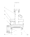
Fig. 1 is a general structure schematic diagram of the present invention
Fig. 2 is a workbench drive part front view of the present invention
Fig. 3 is a workbench drive part left view of the present invention
Fig. 4 is a Working table structure schematic diagram of the present invention
Fig. 5 is a rotary components front view of the present invention
Fig. 6 is that rotary components A of the present invention is to view
Fig. 7 is a turntable structure schematic diagram of the present invention
Fig. 8 is the rotary positioning mechanism structural representation that cooperates with turntable of the present invention
Fig. 9 is the modular construction schematic diagram of presenting a theatrical performance as the last item on a programme of the present invention
Figure 10 is a press platform structure schematic diagram of the present invention
Figure 11 is the rotary part detent mechanism schematic diagram on of the present invention the presenting a theatrical performance as the last item on a programme
Figure 12 is a press platform structure schematic diagram of the present invention
Figure 13 is a magazine structural representation of the present invention
Figure 14 is a nylon fork structural representation of the present invention
Figure 15 is a rotation fork structural representation of the present invention
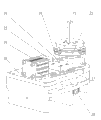
Figure 16 is a cutting mechanism structural representation of the present invention
:1- 2- 3- 4- 5-6- 7- 8- 9- 10- 11-12- 13- 14- 15- 16- 17- 18- 19- 20- 21- 22- 23- 24-25- 26- 27- 28- 29-U 30- 31- 32-33- 34- 35- 36-37- 38- 39- 40- 41-42- 43- 44- 45-46- 47- 48- 49-A 50- 51-B 52- 53- 54-55- 56- 57- 58- 59-60- 61- 62- 63-64- 65- 66- 67-68- 69- 70-71- 72- 73-74- 75- 76-77- 78- 79-80- 81- 82-
The specific embodiment
The present invention will be described below in conjunction with accompanying drawing:
Edger unit for polaroid comprises frame 61, workbench, electric control cabinet 59 and tool motion mechanism, is provided with the program of control entire equipment work in electric control cabinet 59;
Apparatus of the present invention are broadly divided into three parts, promptly frame 61, in the workbench that is provided with on the left-half of frame 61 part and the tool motion mechanism part that on the right half part of frame 61, is provided with.On frame 61, guide rail is installed and pays 75, workbench pay at this guide rail the portal frame 60 that can move to tool motion mechanism on 75 from the left side below, the left side for the treatment of to be withdrawn under the portal frame again after polaroid is cut frame.Whole move and cutwork by the procedure auto-control in the electric control cabinet 59.
On frame 61, also be set with motor mount 81, table drive motor 82 is fixedly mounted on a side of motor mount 81, table lead screw fixed bearing 79 is fixedly mounted on the opposite side of motor mount 81, and table lead screw 76 links together by table lead screw shaft coupling 80 and table drive motor 82.Be installed with screw Connection Block 77 on the workbench, table lead screw nut 78 is fixed together with screw Connection Block 77, and table base 1 is fixed together with the slide block that the movable workbench guide rail is paid on 75.When table drive motor 82 drove table lead screw 76 rotations, table lead screw nut 78 drive workbench were finished to the straight-line feed of tool motion mechanism and are withdrawed from motion, thereby finish the cutwork to the side of polaroid.
The right-hand part of frame 61 is provided with portal frame 60, on the left column of portal frame 60, be set with left tool motion guide rail 62, on left tool motion guide rail 62, be movably set with left cutterhead installing rack 63, the lower end of left side cutterhead installing rack 63 is set with left spindle motor 64, its output shaft is provided with left cutterhead 65, on the right column of portal frame 60, be set with right tool motion guide rail 68, on right tool motion guide rail 68, be movably set with right cutterhead installing rack 66, the lower end of right cutterhead installing rack 66 is set with right spindle motor 67, its output shaft is provided with right cutterhead, right side on the crossbeam of portal frame 60 is set with knife rest mobile motor mount pad 69, knife rest moves fixed support 71 and knife rest moves movable supporting 72, moving fixed support 71 and knife rest at knife rest moves and is provided with knife rest in the movable supporting 72 and moves leading screw 73, knife rest moves leading screw 73 and is fixed together with the upper end of left cutterhead installing rack 63 by right-handed nut 74, knife rest moves the upper end of leading screw 73 by left-handed nut and right cutterhead installing rack 66 and is fixed together, knife rest mobile motor 70 drives knife rest and moves leading screw 73 rotations, knife rest moves leading screw 73 and drives a left side, the right-handed nut, left-handed nut drives right cutterhead installing rack 66 right-handed nuts and drives left cutterhead installing rack 63, realizes the cutting to polaroid.
Workbench comprises table base 1, the support 2 of presenting a theatrical performance as the last item on a programme, turntable 3 and present a theatrical performance as the last item on a programme 4.Many group turntables 3 can be set on this workbench and present a theatrical performance as the last item on a programme 4.Be installed with motor 6 being set with on the frame 1 on motor mount 5, this motor mount, the output shaft of motor 6 links together by shaft joint 7 and the leading screw 10 that is connected on fixed support 8 and the movable supporting 9, be set with guide rail and pay 11 on table base 1, this guide rail is paid 11 and is provided with and can pays the 11 tooth bar installing plates 12 that horizontally slip along guide rail.Leading screw 10 is provided with feed screw nut 13, and feed screw nut 13 is fixedly installed on an end of connecting plate 14, and the other end of connecting plate 14 and tooth bar installing plate 12 are fixed together; Motor 6 drives leading screw 10 and rotates, leading screw 10 drives feed screw nut 13 move left and right, feed screw nut 13 drives tooth bar installing plate 12 by connecting plate 14 and pays 11 realization move left and right along guide rail, and tooth bar installing plate 12 is provided with tooth bar 15, tooth bar 15 and partial gear 16 engagements; On frame 1, be set with turntable 3, the turntable seat 17 of turntable 3 is fixedly installed on the frame 1, be movably set with rotating shaft 18 in the turntable seat 17, upper end is provided with crossed roller bearing 23 down in turntable seat 17, lower end is provided with deep groove ball bearing 22 down in turntable seat 17, rotating shaft 18 cooperates by following crossed roller bearing 23 and following deep groove ball bearing 22 with turntable seat 17, and rotating shaft 18 is passed through from turntable seat 17, be provided with partial gear 16 in the bottom of rotating shaft 18, this partial gear 16 can drive rotating shaft 18 under external force and rotate, be set with a rotating disk 21 in rotating shaft 18 upper ends, be set with turntable square column 25 on the rotating disk 21,21 outward flange downside places are provided with turntable activity orientation piece 24 at rotating disk, on frame 1, be set with turntable weld holder 19, on turntable weld holder 19, be set with turntable installing plate 20, the side that reaches turntable 3 on turntable installing plate 20 is provided with positioning cylinder 26, on turntable installing plate 20, be set with positioning guide rail 27, this positioning guide rail 27 is provided with positioning sliding block 28, this positioning sliding block 28 is provided with U-shaped fork 29, the output shaft that this U-shaped is pitched 29 1 ends and positioning cylinder 26 links together, the side that reaches turntable 3 on turntable installing plate 20 also is set with turntable stationary positioned piece 30, when the turntable activity orientation piece 24 of the dial rotation in the turntable 3 on making it contacts with turntable stationary positioned piece 30, U-shaped fork 29 travels forward under the promotion of positioning cylinder 26, the jaw of U-shaped fork 29 is tight with turntable stationary positioned piece 30 forks with turntable activity orientation piece 24, thereby has guaranteed the accurate location of the rotating disk on the turntable 3.21 outward flange downside places also are provided with another turntable activity orientation piece at rotating disk, and 24 one-tenth an angle of 90 degrees of this turntable activity orientation piece and turntable activity orientation piece are in order to the accurate location of realizing when turntable and presenting a theatrical performance as the last item on a programme and revolving the turntable after turning 90 degrees when compressing polaroid
On the support 2 of presenting a theatrical performance as the last item on a programme directly over the table base 1, be set with the installation base plate 35 of presenting a theatrical performance as the last item on a programme that level is installed, installation base plate 35 centre are provided with by hole 46 presenting a theatrical performance as the last item on a programme, both sides upper fixed at the installation base plate 35 of presenting a theatrical performance as the last item on a programme is provided with a left side, right plate 37, on a left side, right 37 upper ends are set with oil cylinder installation base plate 36, be set with oil cylinder 34 on the oil cylinder installation base plate 36, left plate is fixedlyed connected with the slide block 40 that a secondary guide rail is paid, the slide block guide rail 41 that this guide rail is paid is fixed on the axle 45 of presenting a theatrical performance as the last item on a programme, right plate is fixedlyed connected with the slide block that another secondary guide rail is paid, the slide block guide rail that this guide rail is paid is fixed on the another side of the axle 45 of presenting a theatrical performance as the last item on a programme, axle 45 the upper end of presenting a theatrical performance as the last item on a programme is fixed together by the output shaft of universal knot 47 with oil cylinder 34, what axle 45 the lower end head of presenting a theatrical performance as the last item on a programme passed the installation base plate 35 of presenting a theatrical performance as the last item on a programme passes through hole 46, lower end head outer setting at the axle 45 of presenting a theatrical performance as the last item on a programme that passes through hole 46 that stretches out the installation base plate 35 of presenting a theatrical performance as the last item on a programme has cup-shaped upper holder 33, be provided with crossed roller bearing 42 in the inner top side of this cup-shaped upper holder 33, be provided with deep groove ball bearing 43 in the inside lower end of cup-shaped upper holder 33, axle 45 the head portion of presenting a theatrical performance as the last item on a programme cooperates with cup-shaped upper holder 33 by these two bearings, realize of the rotation of cup-shaped upper holder 33 around the axle 45 of presenting a theatrical performance as the last item on a programme, fixedly connected with the square column 39 of presenting a theatrical performance as the last item on a programme in bottom at cup-shaped upper holder 33, square column 39 bottoms of presenting a theatrical performance as the last item on a programme are set with nylon and insert 44 in order to push down polaroid.Below installation base plate 35 left sides of presenting a theatrical performance as the last item on a programme, be set with the locking cylinder seat 31 of presenting a theatrical performance as the last item on a programme, below installation base plate 35 right sides of presenting a theatrical performance as the last item on a programme, be set with push rod mount pad 38, on the locking cylinder seat 31 of presenting a theatrical performance as the last item on a programme, be set with locking cylinder 48, the output shaft of locking cylinder 48 is fixedlyed connected with an end of push rod 52, the other end of push rod is movably arranged on the push rod mount pad 38, on push rod 52, fixedly install a circular briquetting 50, at the arranged outside of the cup-shaped upper holder 33 activity orientation piece B that presents a theatrical performance as the last item on a programme, locking cylinder 48 promote push rods 52 and on circular briquetting 50 and the arranged outside of the cup-shaped upper holder 33 accurate location that has the activity orientation piece B that presents a theatrical performance as the last item on a programme to cooperate realization to present a theatrical performance as the last item on a programme.Also be provided with the activity orientation piece A that presents a theatrical performance as the last item on a programme in the outside of cup-shaped upper holder 33, the activity orientation of presenting a theatrical performance as the last item on a programme piece A becomes an angle of 90 degrees with the activity orientation piece B that presents a theatrical performance as the last item on a programme, and revolves the accurate location of presenting a theatrical performance as the last item on a programme after turning 90 degrees when compressing polaroid in order to realize when turntable and to present a theatrical performance as the last item on a programme.
The cup-shaped upper holder 33 rotation an angle of 90 degrees that turntable 3 drives on presenting a theatrical performance as the last item on a programme are to realize by the rotation fork 58 of an activity, this rotates fork 58 and forms by column and at the plug of column both ends setting, rotate on the mobilizable insertion turntable of the following jaw square column 25 of fork 58, the last plug that rotates fork can insert on 4 the square column 39 of presenting a theatrical performance as the last item on a programme of presenting a theatrical performance as the last item on a programme simultaneously, partial gear 16 can drive rotating shaft 18 and rotate, rotating shaft 18 drives turntable square column 25, turntable square column 25 is passed to cup-shaped upper holder 33 with power by rotating fork, make cup-shaped upper holder 33, present a theatrical performance as the last item on a programme square column 39 and turntable square column 25 rotates together synchronously, thereby realizes the up and down synchronously rotation of one pile of polaroid 55 under impaction state.
Claims (2)
1, a kind of edger unit for polaroid comprises frame (61), workbench, electric control cabinet (59) and tool motion mechanism; Workbench is arranged on the left-half of frame (61), cutting mechanism is arranged on the right half part of frame (61), go up in frame (61) and a secondary guide rail to be installed from the left end to the right-hand member to pay (75), the table base of workbench (1) can be paid at guide rail on (75) can move left and right; Electric control cabinet is provided with the work control program in (59); It is characterized in that, table base (1) is provided with turntable (3), on table base (1), be set with the support of presenting a theatrical performance as the last item on a programme (2), the support (2) of presenting a theatrical performance as the last item on a programme is provided with present a theatrical performance as the last item on a programme (4), and turntable (3) and present a theatrical performance as the last item on a programme (4) vertical up and down corresponding the setting can be provided with corresponding turntable (3) and present a theatrical performance as the last item on a programme (4) of many groups on this workbench; The detent mechanism that described table base (1) is provided with rotary components and cooperates with turntable (3), the described support of presenting a theatrical performance as the last item on a programme (2) is provided with the detent mechanism of the rotary part of present a theatrical performance as the last item on a programme (4); On frame (61), also be set with table drive motor (82), table lead screw (76) and table lead screw shaft coupling (80), on workbench, be installed with screw Connection Block (77), table lead screw nut (78) is fixed together with screw Connection Block (77), when table drive motor (82) drove table lead screw (76) rotation, table lead screw nut (78) drive workbench was finished to the straight-line feed of tool motion mechanism and is withdrawed from motion; Right-hand part top in frame (61) is provided with portal frame (60), on the left column of portal frame (60), be set with left tool motion mechanism, on the right column of portal frame (60), be set with right tool motion mechanism, when table feed to following time of portal frame (60) left and right tool motion mechanism polaroid is cut.
2, a kind of edger unit for polaroid according to claim 1, it is characterized in that, at the every group of vertical up and down corresponding turntable (3) and movable magazine (53) that is provided with between (4) of presenting a theatrical performance as the last item on a programme that is provided with, this magazine (53) is the door font, its inner chamber is identical with the polaroid shape, inner cavity size becomes matched in clearance with polaroid appearance and size, be movably set with movable cushion block (54) at the magazine inner bottom part, the one pile of polaroid (55) of can packing on this movable cushion block (54) is provided with charging locating slot (56) in magazine (53) bottom; At the turntable (3) and the movable rotation fork (58) that is provided with between (4) of presenting a theatrical performance as the last item on a programme, be movably set with U-shaped nylon fork (57) at the following jaw place that rotates fork (58), nylon fork (57) is arranged on magazine (53) and below magazine (53) is filled up, and realizes the location before the cutting of one pile of polaroid.
Priority Applications (1)
| Application Number | Priority Date | Filing Date | Title |
|---|---|---|---|
| CN200810055342A CN100579722C (en) | 2008-07-03 | 2008-07-03 | Edging unit for polaroid |
Applications Claiming Priority (1)
| Application Number | Priority Date | Filing Date | Title |
|---|---|---|---|
| CN200810055342A CN100579722C (en) | 2008-07-03 | 2008-07-03 | Edging unit for polaroid |
Publications (2)
| Publication Number | Publication Date |
|---|---|
| CN101352823A true CN101352823A (en) | 2009-01-28 |
| CN100579722C CN100579722C (en) | 2010-01-13 |
Family
ID=40305972
Family Applications (1)
| Application Number | Title | Priority Date | Filing Date |
|---|---|---|---|
| CN200810055342A Active CN100579722C (en) | 2008-07-03 | 2008-07-03 | Edging unit for polaroid |
Country Status (1)
| Country | Link |
|---|---|
| CN (1) | CN100579722C (en) |
Cited By (11)
| Publication number | Priority date | Publication date | Assignee | Title |
|---|---|---|---|---|
| CN101811284A (en) * | 2010-05-09 | 2010-08-25 | 无锡上机磨床有限公司 | Numerical-control silicon briquette double-surface lapping machine |
| CN102862154A (en) * | 2012-09-28 | 2013-01-09 | 太原风华信息装备股份有限公司 | Rotary press table for machining laminated polarizers in middle and small size |
| CN104308689A (en) * | 2014-10-29 | 2015-01-28 | 深圳市新昂慧科技有限公司 | Automatic edge grinding machine for polarizer |
| JP2015072453A (en) * | 2013-09-04 | 2015-04-16 | 住友化学株式会社 | Method for manufacturing polarizing plate with processed end face |
| JP2015072454A (en) * | 2013-09-04 | 2015-04-16 | 住友化学株式会社 | Method for manufacturing polarizing plate with processed end face |
| CN105834884A (en) * | 2015-01-30 | 2016-08-10 | 住华科技股份有限公司 | Polarizing plate and method for manufacturing same |
| CN107877292A (en) * | 2017-12-28 | 2018-04-06 | 深圳市新昂慧科技有限公司 | A kind of straight flange irregular edge grinder |
| CN111230600A (en) * | 2020-01-13 | 2020-06-05 | 俞烽 | Liquid crystal polarizer cutting and edging processing technology |
| CN111687712A (en) * | 2020-05-08 | 2020-09-22 | 深圳市高美福商显科技有限公司 | Polaroid cutting processing technology |
| CN111843705A (en) * | 2020-07-09 | 2020-10-30 | 魏亚凤 | Toy building blocks triangular prism chamfer equipment of polishing |
| CN113635379A (en) * | 2021-10-18 | 2021-11-12 | 中电科风华信息装备股份有限公司 | Approximate processing method for convex circular arc of corner of polaroid |
-
2008
- 2008-07-03 CN CN200810055342A patent/CN100579722C/en active Active
Cited By (13)
| Publication number | Priority date | Publication date | Assignee | Title |
|---|---|---|---|---|
| CN101811284A (en) * | 2010-05-09 | 2010-08-25 | 无锡上机磨床有限公司 | Numerical-control silicon briquette double-surface lapping machine |
| CN102862154A (en) * | 2012-09-28 | 2013-01-09 | 太原风华信息装备股份有限公司 | Rotary press table for machining laminated polarizers in middle and small size |
| JP2015072453A (en) * | 2013-09-04 | 2015-04-16 | 住友化学株式会社 | Method for manufacturing polarizing plate with processed end face |
| JP2015072454A (en) * | 2013-09-04 | 2015-04-16 | 住友化学株式会社 | Method for manufacturing polarizing plate with processed end face |
| CN104308689A (en) * | 2014-10-29 | 2015-01-28 | 深圳市新昂慧科技有限公司 | Automatic edge grinding machine for polarizer |
| CN105834884B (en) * | 2015-01-30 | 2017-12-12 | 住华科技股份有限公司 | Polarizing plate and method for manufacturing same |
| CN105834884A (en) * | 2015-01-30 | 2016-08-10 | 住华科技股份有限公司 | Polarizing plate and method for manufacturing same |
| CN107877292A (en) * | 2017-12-28 | 2018-04-06 | 深圳市新昂慧科技有限公司 | A kind of straight flange irregular edge grinder |
| CN111230600A (en) * | 2020-01-13 | 2020-06-05 | 俞烽 | Liquid crystal polarizer cutting and edging processing technology |
| CN111230600B (en) * | 2020-01-13 | 2021-07-23 | 恒美光电股份有限公司 | Liquid crystal polarizer cutting and edging processing technology |
| CN111687712A (en) * | 2020-05-08 | 2020-09-22 | 深圳市高美福商显科技有限公司 | Polaroid cutting processing technology |
| CN111843705A (en) * | 2020-07-09 | 2020-10-30 | 魏亚凤 | Toy building blocks triangular prism chamfer equipment of polishing |
| CN113635379A (en) * | 2021-10-18 | 2021-11-12 | 中电科风华信息装备股份有限公司 | Approximate processing method for convex circular arc of corner of polaroid |
Also Published As
| Publication number | Publication date |
|---|---|
| CN100579722C (en) | 2010-01-13 |
Similar Documents
| Publication | Publication Date | Title |
|---|---|---|
| CN100579722C (en) | Edging unit for polaroid | |
| CN104308538B (en) | A kind of numerical control lock core unit mahine | |
| CN110465579B (en) | Automatic punching equipment and using method thereof | |
| CN104875019A (en) | Electronic valve automatic processing combination device | |
| CN204221362U (en) | A kind of numerical control lock core unit mahine | |
| CN201235481Y (en) | Edger unit for polarizing filter | |
| CN112405061A (en) | Hub deburring automation equipment | |
| CN212705571U (en) | Differential case body disc mills two-way fixed frock | |
| CN201776918U (en) | Punching machine using sliding seat to adjust height of punch | |
| CN101398500B (en) | Rotating and positioning device for processing polaroid | |
| CN209953870U (en) | High-precision end socket beveling machine | |
| CN204603785U (en) | Electronic valve processes combination unit automatically | |
| CN109366185B (en) | Automatic rotary rolling cutting stamping machine tool | |
| CN207372835U (en) | A kind of cutter automatic sharpening equipment | |
| CN100579755C (en) | Compressing apparatus for processing polaroid | |
| CN109108657A (en) | It is a kind of can multi-work piece clamping numerically-controlled machine tool | |
| CN201940677U (en) | Inner circle slicing machine capable of realizing transversal movement of cut materials and simultaneously cutting multiple material slices | |
| CN111151798B (en) | Milling equipment for wall surface or side surface of large part | |
| CN201237650Y (en) | Rotating positioning device for processing polarizer | |
| CN211162842U (en) | Mould processing workbench with emergency stop device | |
| CN107813193A (en) | A kind of cutter automatic sharpening equipment and its grinding method | |
| CN110370046A (en) | Fixture for bacterial type blade root processing | |
| CN216140961U (en) | Automatic winding equipment for metal winding gasket | |
| CN219748208U (en) | Panel processing cuts perforating device | |
| CN215616710U (en) | Transmission device of gantry machine tool spindle gearbox |
Legal Events
| Date | Code | Title | Description |
|---|---|---|---|
| C06 | Publication | ||
| PB01 | Publication | ||
| C10 | Entry into substantive examination | ||
| SE01 | Entry into force of request for substantive examination | ||
| C14 | Grant of patent or utility model | ||
| GR01 | Patent grant | ||
| CP03 | Change of name, title or address | ||
| CP03 | Change of name, title or address |
Address after: 030024 Taiyuan, Shanxi Province, Berlin District, Heping Road, No. 115 Patentee after: CETC Fenghua information equipment Limited by Share Ltd Address before: 030024 Taiyuan Heping Road, Shanxi, No. 159 Patentee before: Taiyuan Fenghua Information Equipment Co., Ltd. |