CN101327828A - Crank arm assembly and related crank arm and element for transmitting torque from the crank arm to a bicycle chain - Google Patents
Crank arm assembly and related crank arm and element for transmitting torque from the crank arm to a bicycle chain Download PDFInfo
- Publication number
- CN101327828A CN101327828A CNA200810125175XA CN200810125175A CN101327828A CN 101327828 A CN101327828 A CN 101327828A CN A200810125175X A CNA200810125175X A CN A200810125175XA CN 200810125175 A CN200810125175 A CN 200810125175A CN 101327828 A CN101327828 A CN 101327828A
- Authority
- CN
- China
- Prior art keywords
- crank arm
- ring
- arm assembly
- connecting device
- slender body
- Prior art date
- Legal status (The legal status is an assumption and is not a legal conclusion. Google has not performed a legal analysis and makes no representation as to the accuracy of the status listed.)
- Pending
Links
Images


Classifications
-
- B—PERFORMING OPERATIONS; TRANSPORTING
- B62—LAND VEHICLES FOR TRAVELLING OTHERWISE THAN ON RAILS
- B62M—RIDER PROPULSION OF WHEELED VEHICLES OR SLEDGES; POWERED PROPULSION OF SLEDGES OR SINGLE-TRACK CYCLES; TRANSMISSIONS SPECIALLY ADAPTED FOR SUCH VEHICLES
- B62M3/00—Construction of cranks operated by hand or foot
- B62M3/003—Combination of crank axles and bearings housed in the bottom bracket
-
- B—PERFORMING OPERATIONS; TRANSPORTING
- B62—LAND VEHICLES FOR TRAVELLING OTHERWISE THAN ON RAILS
- B62M—RIDER PROPULSION OF WHEELED VEHICLES OR SLEDGES; POWERED PROPULSION OF SLEDGES OR SINGLE-TRACK CYCLES; TRANSMISSIONS SPECIALLY ADAPTED FOR SUCH VEHICLES
- B62M9/00—Transmissions characterised by use of an endless chain, belt, or the like
- B62M9/04—Transmissions characterised by use of an endless chain, belt, or the like of changeable ratio
- B62M9/06—Transmissions characterised by use of an endless chain, belt, or the like of changeable ratio using a single chain, belt, or the like
- B62M9/10—Transmissions characterised by use of an endless chain, belt, or the like of changeable ratio using a single chain, belt, or the like involving different-sized wheels, e.g. rear sprocket chain wheels selectively engaged by the chain, belt, or the like
-
- Y—GENERAL TAGGING OF NEW TECHNOLOGICAL DEVELOPMENTS; GENERAL TAGGING OF CROSS-SECTIONAL TECHNOLOGIES SPANNING OVER SEVERAL SECTIONS OF THE IPC; TECHNICAL SUBJECTS COVERED BY FORMER USPC CROSS-REFERENCE ART COLLECTIONS [XRACs] AND DIGESTS
- Y10—TECHNICAL SUBJECTS COVERED BY FORMER USPC
- Y10T—TECHNICAL SUBJECTS COVERED BY FORMER US CLASSIFICATION
- Y10T74/00—Machine element or mechanism
- Y10T74/21—Elements
- Y10T74/2164—Cranks and pedals
Abstract
A crank arm assembly (1) for a bicycle, comprising a crank arm (2) and an element (3,3a) for transferring torque from the crank arm (2) to a bicycle chain. The crank arm (2) and the element (3,3a) for transferring torque respectively comprise first (25) and second (34) front coupling means provided with respective matching profiles adapted to be coupled together to transfer torque from the crank arm (2) to the element (3,3a) for transferring torque. In particular, the first and second means for transferring torque comprise respective front toothings, preferably Hirth toothings. The crank arm assembly (1) is very light and is stronger in structure than crank arm assembly known.
Description
Technical field
The present invention relates to a kind of crank arm assembly that is used for bicycle.The invention still further relates to a kind of element that is used for the crank arm of this assembly and is used for moment of torsion is delivered to from above-mentioned crank arm cycle chain.
Background technology
The claim that runs through this specification sheets and enclose, term " crank arm assembly " is used to represent to comprise crank arm and the assembly that is suitable for linking to each other with crank arm with the element that allows to transmit motion to bicycle rear, and this motion is to be applied on the crank arm and by the chain that connects with the crown of bicycle crank by pedal by the rider to be delivered to trailing wheel.
Be known that in right crank arm assembly crown directly connects with right crank arm.For example referring to EP1 354 792 and EP 0 414 907.
In this assembly, right crank arm manufactures star, and comprises a plurality of link arm of extending along with respect to the cooresponding cardinal principle radial direction of crank arm rotation axis.Each link arm on an one sidepiece and its free end comprise and be used for the surface that connects with crown.This crown comprises ring-type element in turn, and this ring-type element radially has toothing on the outer ring surface at it, and inwardly has on annular surface in its footpath and to be used for a plurality of elements of connecting with crank arm.Especially, each element that is used for connecting with crank arm is along extending as cantilever ground from the inside annular surface in described footpath with respect to the cardinal principle radial direction of crown rotation axis, and on an one sidepiece and the inside free end in its footpath comprise and be used for the surface that connects with the counterpart arm of crank arm.Connection between crank arm and the crown realizes by a plurality of screws, and this screw is inserted in the corresponding surface of the connection element of the arm of crank arm and crown and goes up in the formed corresponding aperture.
The assembly of type described above need use the crank arm of being made by metallic material, and is therefore heavyly special.Really, in this assembly, the Motion Transmission from the crank arm to the crown occurs in limited and local zone (particularly, being provided with the location of screw), produces high stress concentration in these zones.In addition, the crank arm of this assembly is thick and heavy especially and huge, must be provided for the spoke that connects with crown on crank arm.In addition, the use of metal crank can not be satisfied the especially demand of the lasting increase that minimizes bicycle assembly parts weight of race bicycle maker of bicycle maker.
Be known that in right crank arm crown connects with right crank arm by inserting the adapter dish.For example referring to EP 0 002 964 and EP 0 909 697.
In this assembly, the transmission of motion from the crank arm to the adapter realizes that by connecting device this connecting device extends radially outwardly and radially extends internally in adapter in crank arm.
The applicant observes, traditional being set up in the crank arm assembly that uses adapter, the setting of the connecting device that extends radially outwardly on crank arm needs such connecting device necessarily, and this connecting device is fabricated in the swedged ring part of having of crank arm place.Therefore, crank arm to the overall contact surface of adapter less relatively aspect the size.This causes the connection place between crank arm and adapter to produce high-stress concentration, has the secondary danger of fracture crank arm, if special crank arm is made by light material.
Summary of the invention
Technical matters on basis of the present invention is to make a kind of special lightweight and than the current known structurally stronger right crank arm assembly of right crank arm assembly.
Therefore, in a first aspect of the present invention, the present invention relates to a kind of crank arm assembly that is used for bicycle, comprise crank arm and the element that is used for moment of torsion is delivered to from described crank arm cycle chain, it is characterized in that, described crank arm and the described element that is used for transfer torque comprise separately first and second before connecting devices, connecting device is provided with the coupling profile separately that is suitable for being linked together before first and second, so that described moment of torsion is passed to the described element that is used for transfer torque from described crank arm.
Here in Shuo Ming the context of the present invention, the said elements that is used for transfer torque can comprise the crown of bicycle crank, or be suitable for operationally being arranged in adapter between crank arm and the crown, be used for crank arm is connected to crown, this adapter is the element different with crown, or is made for single member with crown.
Advantageously, connecting device allows above-mentioned connecting device to be fabricated on the ring part place of crank arm in crank arm and before the element that is used for transferring a torque to cycle chain uses, and this ring part has than the big diameter of feasible diameter that is provided for radially connecting with adapter in traditional crank.Therefore, can provide the element that is used for transfer torque that has than extension bigger in the traditional crank arm for the whole contact surface of crank arm, more uniform distribution of load is provided, and therefore reduce stress concentration.
Preferably, the first and second preceding connecting devices comprise toothing separately, end face tooth (Hirth) toothing more preferably.
Advantageously, on the crank arm and be used to transfer torque to use coupling on the element of cycle chain before toothing, can carry out homogeneity and the transmission of well-distributed moment of torsion, so have advantage aspect the structural strength of transmission of motion efficient and assembly.More preferably, the use of end face tooth toothing is special to be allowed at crank arm and is used for the high precision centering of the connection between the element of transfer torque, also allows high efficiency Motion Transmission.
In the preferred embodiment of crank arm assembly of the present invention, crank arm comprises slender body, this slender body has first pedestal that is used for connecting with bicycle pedal at its first free end place, and have at its second free end place and to be used for second pedestal that connects with first free end of the axle of underframe assembly, above-mentioned first connecting device be limited at above-mentioned slender body around described second pedestal circumferentially on the ring part of extension.
Preferably, above-mentioned first toothing is by a plurality of recessed qualifications, and described a plurality of being recessed in is formed in the described slender body not from the surface that described slender body overhangs out.
Advantageously, preceding connecting device is fabricated on the body of crank arm thus, does not need to provide bar or the part that overhangs out from this body.Therefore the crank arm of crank arm assembly of the present invention has low-down axial volume, thereby the embodiment of following underframe assembly can be provided, and in this underframe assembly, bearing is accommodated in the outside of casing box of the axle of this assembly that is arranged in the bicycle frame.Because bearing very near corresponding crank arm, is applied to the deflection of shaft moment of torsion by pedal and has the amplitude that reduces, so this embodiment is an advantageous particularly and preferred.
In first embodiment of crank arm assembly of the present invention, the first preceding connecting device extends on the described ring part of the slender body of crank arm equably.
In the alternate embodiments of crank arm assembly of the present invention, first connecting device along angular dimension less than at least two circular arcs of 180 °, preferably on the described ring part of the slender body of crank arm, extend along three circular arcs.
Preferably, except passing through above-mentioned first and second connecting devices, crank arm connects with the said elements that is used for transfer torque by a plurality of screws.
In the preferred embodiment of crank arm assembly of the present invention, in this case, crank arm and the said elements that is used for transfer torque comprise respectively and are used for a plurality of first holes and second hole that are coupled to each other by described screw.
Preferably, described first hole is a through hole, and is formed on the described ring part of slender body of crank arm.
In first embodiment of crank arm assembly of the present invention, particularly at first connecting device in the embodiment of described ring part extend past angular dimension less than 180 ° circular arc of the slender body of crank arm, described first hole is formed between two circular arcs in succession.
In alternative embodiment, particularly in the embodiment that the connecting device of crank arm extends equably along the described ring part of the slender body of crank arm, described first hole is integrated in above-mentioned first connecting device.
With the specific embodiment of assembly of the present invention irrespectively, be provided for the hole that connects with the element that is used for transfer torque by screw at the first connecting device place, permission is at crank arm and be used for carrying out stable especially connection between the element of transfer torque, promptly at crank arm (crank arm being applied driving torque by pedal) be used for not having undesirable relative displacement between the element (stand applied by chain by crown opposing moment of torsion) of transfer torque.In addition, advantageously, because the screw that is inserted in the above-mentioned hole has low-down axial volume, therefore can be produced as follows the embodiment of underframe assembly, wherein, bearing is accommodated in the outside that is arranged at the casing box in the bicycle frame.
In the alternate embodiments of crank arm assembly of the present invention, at least some holes in above-mentioned first hole are formed on the part that being positioned at of above-mentioned slender body be formed with the radially inner side of the ring part of connecting device before first or the outside.In the another alternate embodiments of crank arm assembly of the present invention, crank arm assembly comprises that ring nut replaces above-mentioned screw, this ring nut be suitable for the opposition side of described second connecting device on abut on the element that is used for transfer torque and operate, this ring nut is provided with and is used for the negative thread that connects with the thread end of the axle of underframe assembly.
Above-mentioned second pedestal preferably includes negative thread, but alternately, and it can comprise profile in the trough of belt or have square interior profile.
Preferably, crank arm is made by light-metal alloy or the preferred carbon fiber of composite material.
Under the situation that crank arm is made by composite material, above-mentioned first connecting device can be formed on the inserts of being made by metallic material, and this inserts is incorporated in the crank arm.
Preferably, the said elements that is used for transfer torque comprise first footpath inwardly ring-type element, with described first ring-type element concentric second radially the outer ring element and between described first ring-type element and described second ring-type element a plurality of arms of extension radially, wherein said second connecting device is limited on described first ring-type element.
Illustrate that as top the element that is used for transfer torque can comprise the crown or the adapter of bicycle crank, this adapter intention is used for operationally being arranged between the crown of crank arm and fluted disc, is used for moment of torsion is delivered to crown from crank arm.Adapter can be made for single member with crown, or is made for different component with crown.
Under the situation of using adapter, preceding connecting device is produced on the adapter.
Advantageously, use adapter to make it possible to use as lower crank in the connection between crank arm and crown, employed crank volume is little and weight is little in the traditional components that these cranks are more direct than crank arm with crown connects.In addition, not being arranged to the crank arm that directly connects with crown by screw can be made by light material.Realizing that for identical structural strength adapter also can be made by light material under the situation about reducing significantly of assembly weight.
In first embodiment of crank arm assembly of the present invention, second connecting device extends equably along first ring-type element.
In the alternate embodiments of crank arm assembly of the present invention, second connecting device along angular dimension less than at least two circular arcs of 180 °, preferably on first ring-type element, extend along three circular arcs.
Preferably, above-mentioned second hole is tapped bore and is formed on first ring-type element, more preferably is formed between two circular arcs in succession.
Alternately, above-mentioned second hole can be integrated in second connecting device.
Alternately, at least some holes in the above-mentioned hole are formed on the radially inner side that is positioned at first ring-type element of the element that is used for transfer torque or the part in the outside.
Preferably, under the situation of having used adapter, described adapter is by light-metal alloy system or the preferred carbon fiber manufacturing of composite material.
More preferably, under the situation of using the adapter of being made by composite material, above-mentioned connecting device can be formed on the metal insert that is combined in the described adapter.
Preferably, crank arm assembly of the present invention comprises at least one deformation-sensor of linking to each other with at least one arm of the arm of the element that is used for transfer torque, is more preferably strain gage.Advantageously, this sensor is used for the torsional deflection that the element of transfer torque stands during pedal.Really, during pedal, the inside ring-type element in the footpath that connects with crank arm stands the driving torque that applied by pedal by the rider, and the radially outer ring element that connects with chain stands the opposing moment of torsion that applied by chain.The torsional deflection that is used for the element of transfer torque can provide this element structural strength indication and by the indication of the power that the rider applied, at the design phase of the parts of bicycle crank arm component with during analyzing behavior during these parts are travelling, this information all of great use.
Preferably, crank arm assembly of the present invention comprises four deformation-sensors, and each deformation-sensor in these four deformation-sensors links to each other with respective arms.In this way, can carry out more homogeneous and reliable detection for the distortion that element stood that is used for transfer torque.
Preferably, described sensor is connected to electric balance.
Preferably, crank arm assembly of the present invention comprises at least one electronics package, and described at least one electronics package is accommodated at least one zone that is defined between two alternate arms.
Crank arm assembly of the present invention also preferably includes a pair of lid, and described a pair of lid is suitable for being on the axial opposed side at above-mentioned second ring-type element and connects with the said elements that is used for transfer torque.
Preferably, at least one lid in the described lid is a solar cell panel.
In a second aspect of the present invention, the present invention relates to a kind of crank arm that is used for bicycle, comprise slender body, this slender body has first pedestal that is used for connecting with bicycle pedal at its first free end place, and have at its second free end place and to be used for second pedestal that connects with first free end of the axle of underframe assembly, it is characterized in that this crank arm comprises preceding connecting device at the ring part place around described second pedestal circumferentially extends of described slender body.
Advantageously, this crank arm can be used for the assembly of the above-mentioned type.
Preferably, all 26S Proteasome Structure and Function features of discussing with reference to the crank arm of crank arm assembly of the present invention above this crank arm has independently or in combination, and therefore have all above-mentioned advantages.
Especially, preceding connecting device preferably includes toothing, more preferably the toothing of end face tooth.
Preferably, described toothing is by a plurality of recessed qualifications, and described a plurality of being recessed in is formed in the described slender body not from the surface that described slender body overhangs out.
In first embodiment of crank arm of the present invention, preceding connecting device extends equably along the described ring part of the slender body of crank arm.
In the alternate embodiments of crank arm of the present invention, connecting device preferably extends on the described ring part of the slender body of crank arm along three circular arcs along at least two circular arcs of angular dimension less than 180 °.
Preferably, crank arm of the present invention comprises a plurality of holes, and described a plurality of holes are formed on the described ring part of slender body of crank arm.
Preferably, described hole is a through hole, and more preferably is formed between two circular arcs in succession.
Alternately, above-mentioned hole is integrated in above-mentioned second connecting device.
Alternately, at least some holes in the above-mentioned hole are formed on the part in the radially inner side of described ring part of the slender body that is positioned at crank arm of described slender body or the outside.
Preferably, above-mentioned second pedestal comprises negative thread, but alternately can comprise profile in the trough of belt or have square interior profile.
Preferably, slender body is more preferably made by carbon fiber by light-metal alloy or composite material.
Under the situation that the slender body of crank arm is made by composite material, crank arm can comprise the inserts of being made by metallic material, and above-mentioned preceding connecting device is formed in the described inserts.
In a third aspect of the present invention, the present invention relates to a kind of being used for moment of torsion is delivered to the element of cycle chain from crank arm, it is characterized in that this element comprises: first footpath is ring-type element inwardly; The second radially outer ring element concentric with described first ring-type element; And a plurality of arms that between described first ring-type element and described second ring-type element, radially extend, the preceding connecting device that has described crank arm is limited on described first ring-type element.
Advantageously, this element can be used for the assembly of the above-mentioned type.
Preferably, all 26S Proteasome Structure and Function features of discussing with reference to the element that is used for transfer torque of crank arm assembly of the present invention above this element has independently or in combination, and therefore have all above-mentioned advantages.
Especially, said elements can comprise the crown of the fluted disc that is used for bicycle, or alternately comprise adapter, this adapter and above-mentioned crown are made as different component, and be suitable for operationally being arranged in crank arm and be used between the crown of fluted disc of bicycle, above-mentioned before connecting device be formed in this case on the described adapter.
The connecting device that has crank arm preferably includes toothing, more preferably comprises the toothing of end face tooth.
In first embodiment of adapter of the present invention, the connecting device that has crank arm extends equably along first ring-type element.
In the alternate embodiments of adapter of the present invention, the connecting device that has crank arm preferably extends on first ring-type element along three circular arcs along at least two circular arcs of angular dimension less than 180 °.
Preferably, the element that is used for transfer torque of the present invention comprises a plurality of tapped bore, is used for connecting with crank arm, and described a plurality of tapped bore are formed on first ring-type element.
Preferably, described hole is formed between two circular arcs in succession.
Alternately, they are integrated in the connecting device that has crank arm.
Alternately, at least some holes in the described hole are formed on the part in the radially inner side of described first ring-type element of being positioned at of described element or the outside.
Preferably, under the situation of using adapter, this adapter is made by light-metal alloy or the preferred carbon fiber of composite material.
More preferably, under the situation of using the adapter of being made by composite material, above-mentioned connecting device can be formed on the metal insert that is attached in the described adapter.
In a preferred embodiment of the invention, the element that is used for transfer torque of the present invention comprises the deformation-sensor that links to each other with its at least one arm of arm, preferred strain gage.
More preferably, have four sensors, each sensor in four sensors links to each other with respective arms.
Described sensor preferably connects as electric balance.
Preferably, the element that is used for transfer torque of the present invention comprises at least one electronics package, and described at least one electronics package is accommodated at least one zone that is defined between two alternate arms.
The element that is used for transfer torque of the present invention also preferably includes a pair of lid, and described a pair of lid is suitable for being on the axial opposed side at above-mentioned second ring-type element and connects with the said elements that is used for transfer torque.
Preferably, at least one lid in the described lid is a solar cell panel.
In a fourth aspect of the present invention, the present invention relates to a kind of underframe assembly that is used for bicycle, comprise the crank arm assembly of the above-mentioned type.
Preferably, all 26S Proteasome Structure and Function features of discussing with reference to crank arm assembly of the present invention above this underframe assembly has independently or in combination, and therefore have all above-mentioned advantages.
In a fifth aspect of the present invention, the present invention relates to a kind of bicycle that comprises the crank arm assembly of the above-mentioned type.
Preferably, all 26S Proteasome Structure and Function features of discussing with reference to crank arm assembly of the present invention above this bicycle has independently or in combination, and therefore have all above-mentioned advantages.
Description of drawings
With reference to the accompanying drawings, from following DETAILED DESCRIPTION OF THE PREFERRED more of the present invention, it is clearer that other features and advantages of the present invention will become.Among the figure:
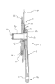
Fig. 1 is the decomposition diagram of first embodiment of crank arm assembly of the present invention, and wherein the element of representing with reference number 3 is squeezed, so that features more of the present invention as seen;
Fig. 2 is the transparent view of crank arm of the crank arm assembly of Fig. 1 of seeing from first point of observation;
Fig. 3 is the front elevation of crank arm part of the crank arm assembly of Fig. 1 of seeing from the point of observation opposite with point of observation Fig. 2;
Fig. 4 is the view of observing from the top of the crank arm of the crank arm assembly of Fig. 1;
Fig. 5 is the longitudinal cross-section of underframe assembly that comprises the crank arm assembly of Fig. 1;
Fig. 6 is the longitudinal cross-section of second embodiment of crank arm assembly of the present invention;
Fig. 7 is the decomposition diagram of the 3rd embodiment of crank arm assembly of the present invention, and wherein the element of representing with reference number 3 is squeezed, so that features more of the present invention as seen;
Fig. 8 is the front elevation of part of another embodiment of the crank arm of crank arm assembly of the present invention.
The specific embodiment
In the accompanying drawing of enclosing, reference number 1 expression is according to crank arm assembly of the present invention.Particularly, crank arm assembly 1 is right crank arm assembly, and intention is used for the underframe assembly of bicycle, race bicycle preferably, thus the crown by bicycle crank will move and be delivered to the chain of bicycle from crank arm.
Fig. 1 shows first embodiment of crank arm assembly of the present invention.The crank arm of this crank arm assembly is shown specifically in Fig. 2-4, and Fig. 5 shows the underframe assembly of the crank arm assembly that has used Fig. 1.
With reference to above-mentioned accompanying drawing 1-5, crank arm assembly 1 comprises: crank arm 2 is suitable for use as right crank arm; With adapter 3a, be suitable for connecting, thereby permission is delivered to moment of torsion the trailing wheel (not shown) of bicycle from crank arm 2 with crank arm 2 and crown (indicating with 200 among Fig. 5).This moves through pedal and is applied to crank arm 2, and is delivered to trailing wheel by the chain (not shown) that connects with crown 200.
Crank arm 2 comprises slender body 20, and this slender body is preferably made by light-metal alloy or composite material, and this light-metal alloy is aluminum alloy or other light alloy for example.
In this case, composite material can comprise the structural fibers that is combined in the polymer material.Typically, structural fibers is selected from the group of being made up of carbon fiber, glass fibre, aramid fibre, ceramic-fibre, boron fiber and their combination.Carbon fiber is particularly preferred.
The layout of structural fibers described in the polymer material can be structural fibers piece or sheet random arrangement, fiber the directionless arrangement of cardinal principle layout, fiber the cardinal principle bi-directional arrangement layout or above the combination of situation.
Preferably, polymer material is thermosetting and preferably includes epoxy resin.Yet this does not get rid of the possibility of using thermoplastic material.
In the example shown in Fig. 1-5, pedestal 22 be negative thread and hold shaft element 23a, this shaft element is provided with outside thread at its free end, is used for connecting with crank arm 2.Yet, alternate embodiments is provided, crank arm 2 connects (in this case, pedestal 22 and the free end that is suitable for being contained in the shaft element 23a in the pedestal 22 have cooresponding trough of belt profile) or connects (for example by having square cooresponding profile) by the shape of utilizing match surface to realize by trough of belt and connects with semiaxis 23a in this alternate embodiments.Alternately, shaft element 23a can with crank arm 2 member that forms as one.
In this specification sheets and the claim of enclosing, wording " shaft element " is used for representing constituting the part of a plurality of parts of the axle of underframe assembly.In this case, thus, it is the member different with crank arm 2 that the axle 23 of underframe assembly is formed into, and comprises at least two shaft elements 23 (being shaft element 23a and 23b in the example shown in Figure 6).Alternately, the axle 23 of underframe assembly can be made for integral member.
Crank arm 2 toothing 25 before its free end 20b comprises, this preceding toothing preferably also are the end face flute profiles.Especially, this toothing 25 be formed on crank arm 2 on the ring parts 26 that pedestal 22 circumferentially extends.
Particularly, preceding toothing 25 limits (among Fig. 1-4 only mark wherein some) by a plurality of mutually the same teeth 27, and this tooth 27 is limited between the cooresponding slot 28, this slot also mutually the same (among Fig. 1-4 only mark wherein some).
The quantity of tooth 27 between 2 to 40, more preferably is between 10 to 30 preferably.In the example that illustrates, the quantity of tooth 27 equals 11.
In the embodiment of the crank arm shown in Fig. 1-5 2, before the tooth 27 of toothing 25 circular arc A ', the A ", A ' " that equal α ', α ", α ' " respectively along the angle size be distributed in the ring part 26 of crank arm 2, do not have the area B of tooth and slot to be limited between the above-mentioned arc.
Preferably, angle α ' and α ' " mutually the same, and " bigger than angle α.In the example that illustrates, at circular arc A ' and A ', " locate, between five slots 28, define four teeth 27, yet " locate, between four slots 28, define three teeth 27 at circular arc A.
Preferably, angle α ', α " and α ' " are between about 30 ° and about 120 °.
Shown in Fig. 1,2 and 3, in the area B that between each is by two circular arc A in succession, limits, be formed with through hole 29.This hole 29 is used for admitting screw 29a (Fig. 5 can see one of them), is used for further crank arm 2 being connected to adapter 3a.
In crank arm 2 embodiment that are not illustrated, tooth 27 is evenly distributed on the ring part 26 of crank arm 2 in 360 ° of scopes.Therefore, in this embodiment, the full annular portion 26 of crank arm 2 comprises tooth 27 and slot 28, and does not have the area B that does not have tooth 27 and slot 28.In this case, hole 29 is integrally formed in the toothing 25, and the meaning is, they directly are formed on the tooth 27 of this toothing or on the slot 28, perhaps makes the part in hole 29 be positioned on the tooth and the another part in hole 29 is positioned on the slot 28.
The alternate embodiments of crank arm 2 is provided, and in this alternate embodiments, at least some holes 29 can be fabricated on the part in the radially inner side that is positioned at ring part 26 of slender body 20 of crank arm 2 or the outside, define toothing 25 in this ring part.
The alternate embodiments of crank arm has been shown among Fig. 8.In the figure, indicate with identical reference number with the top corresponding element of element with reference to figure 1-5 explanation.
The different sole cause of the crank arm that illustrates among the crank arm 2 shown in Fig. 8 and top explanation and Fig. 1-5 is, tooth 27 distributes along full annular portion 26 (dotting) equably, and hole 29a and 29b partly are formed on the tooth 27 and part is formed on the slot 28, yet hole 29c is formed on the part 26a of the radial outside that is arranged in the ring part 26 that is formed with toothing 25 of the slender body 20 of crank arm 2.
On first ring-type element 31, be formed with toothing 34, preferably end face tooth toothing, this toothing and toothing 25 couplings that are formed on the crank arm 2.Toothing 34 is suitable for connecting with the toothing 25 of crank arm 2 really, as shown in Figure 5, is delivered to crown 200 thereby allow to move through adapter 3a from crank arm 2.
As shown in fig. 1, in each zone C, form tapped bore 38.This hole 38 is intended to be used to admit the screw 29a in the hole 29 (Fig. 5) of passing crank arm 2, thereby further crank arm 2 is connected with adapter 3a.
In the embodiment of unshowned crank arm 2, tooth 35 is evenly distributed on the ring-type element 31, and is illustrated as top alternate embodiments with reference to crank arm 2.Therefore, in this embodiment, tooth 35 and slot 36 are distributed on the full annular element 31, and do not have the zone C that does not have tooth 35 and slot 36.In this case, hole 38 is integrated in the toothing 34, and the meaning is that they are formed directly on the tooth 35 or slot 36 of this toothing.
Preferably, deformation-sensor, preferred strain gage (among Fig. 1 with 40 signal indication) links to each other with at least one arm 33 on being formed on adapter 3a, thereby can detect the torsional deflection that adapter 3a is stood during pedal.Preferably, this strain gage is an illustrated type in patent application EP 0,386 005, and its content is incorporated in this by the mode of reference.
In a preferred embodiment, have four strain gages 40, each arm 33 all has one, and they are connected according to the electric balance pattern.
The electronics package (not shown) that is used for handling the signal that is detected by strain gage 40 is accommodated in the regional 33a that is limited between two alternate arms 33.Fig. 6 shows the alternate embodiments of crank arm assembly 1 of the present invention.In the figure, corresponding to representing with identical reference number with reference to the element of the described element of figure 1-5.
The crank arm assembly 1 different sole cause of the crank arm assembly of Fig. 6 and Fig. 1-5 is, is not formed for the hole that is coupled to each other by screw on crank arm 2 and adapter 3a.This being coupled to each other when realizing by toothing 25 and 34 in fact also can be realized by the ring nut 50 that is suitable for operating against adapter 3a on the opposition side of toothing 34.For this purpose, ring nut 50 is provided with and is used for the negative thread that connects with the thread end of the pedestal that is inserted into crank arm 2 22 of shaft element 23a.
Fig. 5 and 6 also shows second crown 210 with diameter littler than the diameter of first crown 200, and this second crown also links to each other with adapter 3a.
Fig. 7 shows the alternate embodiments of crank arm assembly 1 of the present invention.In the figure, corresponding to representing with identical reference number with reference to the element of the illustrated element of figure 1-5.
The crank arm assembly 1 different sole cause of the crank arm assembly of Fig. 7 and Fig. 1-5 is, adapter 3a here is and crown 200 member that forms as one.In other words, adapter 3a is limited on the inner radial of crown 200.Therefore, in this embodiment, be to constitute from the element 3 that crank arm 2 is delivered to chain by the assembly that comprises crown 200 and adapter 3a with moment of torsion.
In Fig. 7, show two lids 70 and 71, these two lids 70 and 71 are suitable for the inner radial that defines adapter 3a at crown 200 and are on the axial opposed side and connect with crown 200.Described lid 70 and 71 closures wherein be inserted with the space 33a of above-mentioned electronics package.Two at least one that cover in 70,71 are made of the solar cell panel that is used to this electronics package and sensor 40 energy supplies.This lid 70 also is provided with tightening seal washer 70a.
Further embodiment of the present invention is provided, and in this embodiment, toothing 34 is fabricated directly on the crown 200 and does not use adapter 3a.Therefore, in this embodiment, moment of torsion is made of crown 200 from 3 of the elements that crank arm 2 is delivered to chain.
In all above-mentioned embodiment, under the situation that crank arm 2 and adapter 3 are made by composite material, can provide the inserts of making by metallic material, on this inserts, form toothing 25 and 34.
Claims (87)
1. crank arm assembly (1) that is used for bicycle, comprise crank arm (2) and be used for moment of torsion is delivered to from described crank arm (2) element (3,3a) of cycle chain, it is characterized in that, described crank arm (2) and the described element (3,3a) that is used for transfer torque comprise separately first and second before connecting devices (25,34), connecting devices are provided with the coupling profile separately that is suitable for being coupled to each other before first and second, so that described moment of torsion is passed to the described element that is used for transfer torque (3,3a) from described crank arm (2).
2. crank arm assembly according to claim 1 (1), the wherein said first and second preceding connecting devices comprise first toothing (25) and second toothing (34) respectively.
3. crank arm assembly according to claim 2 (1), wherein said toothing (25,34) is the toothing of end face flute profile.
4. according to each the described crank arm assembly (1) in the aforementioned claim, wherein said crank arm (2) comprises slender body (20), this slender body locates to have first pedestal (21) that is used for connecting with bicycle pedal at its first free end (20a), and locate to have the axle (23 that is used for underframe assembly (100) at its second free end (20b), second pedestal (22) that 23a) first free end connects, wherein said first connecting device (25) be limited at described slender body (20) on the ring part (26) that described second pedestal (22) circumferentially extends.
5. according to claim 4 described crank arm assembly (1) when being subordinated to claim 2 or 3, wherein said first toothing (25) is by a plurality of recessed qualifications, and described a plurality of being recessed in is formed in the described slender body (20) not from the surface that described slender body (20) overhangs out.
6. according to claim 4 or 5 described crank arm assemblies (1), wherein said first connecting device (25) extends equably along the described ring part (26) of described slender body (20).
7. according to claim 4 or 5 described crank arm assemblies (1), wherein said first connecting device (25) is gone up at the described ring part (26) of described slender body (20) less than two circular arcs of 180 ° (A ', A ", A " ') along angular dimension (α) extend at least.
8. crank arm assembly according to claim 7 (1), wherein said first connecting device (25) are gone up at the described ring part (26) of described slender body (20) along three circular arcs (A ', A ", A " ') and are extended.
9. according to each the described crank arm assembly (1) in the aforementioned claim, wherein said crank arm (2) and the described element (3,3a) that is used for transfer torque comprise respectively and are used for a plurality of first holes (29) and second hole (37) that are coupled to each other by screw.
10. according to claim 9 described crank arm assembly (1) when being subordinated to claim 4, wherein said first hole (29) is formed on the described ring part (26) of described slender body (20).
11. crank arm assembly according to claim 10 (1), wherein said first hole (29) is a through hole.
12. according to each the described crank arm assembly (1) when being subordinated to claim 7 or 8 in the claim 9 to 11, wherein said first hole (29) is formed between two circular arcs (A ', A ", A " ') in succession.
13. according to each the described crank arm assembly (1) when being subordinated to claim 6 in the claim 9 to 11, wherein said first hole (29) is integrated in described first connecting device (25).
14. according to each the described crank arm assembly (1) when being subordinated to claim 4 in the claim 9 to 11, at least some holes (29) in wherein said first hole (29) are formed on the part (26a) in the radially inner side that is positioned at described ring part (26) of described slender body (20) or the outside.
15. according to each the described crank arm assembly (1) in the claim 1 to 8, comprise that being suitable for abutting on the opposition side of described second connecting device (34) described adapter (3,3a) goes up the ring nut (50) of operation, described ring nut (50) is provided with and is used for the negative thread that connects with the thread end of the axle of underframe assembly (100) (23,23a).
16. according to each the described crank arm assembly (1) in the claim 4 to 15, wherein said second pedestal (22) comprises negative thread.
17. according to each the described crank arm assembly (1) in the claim 4 to 15, wherein said second pedestal (22) comprises profile in the trough of belt.
18. according to each the described crank arm assembly (1) in the claim 4 to 15, wherein said second pedestal (22) comprises the interior profile with square.
19. according to each the described crank arm assembly (1) in the aforementioned claim, wherein said crank arm (2) is made by light-metal alloy.
20. according to each the described crank arm assembly (1) in the claim 1 to 15, wherein said crank arm (2) is made by composite material.
21. crank arm assembly according to claim 20 (1), wherein said crank arm (2) is made by carbon fiber.
22. according to claim 20 or 21 described crank arm assemblies (1), wherein said crank arm comprises the inserts of being made by metallic material, described first connecting device (25) is formed in the described inserts.
23. according to each the described crank arm assembly (1) in the aforementioned claim, the described element (3) that wherein is used for transfer torque comprises the crown (200) of bicycle crank.
24. crank arm assembly according to claim 23 (1), the described element (3) that wherein is used for transfer torque comprises adapter (3a), this adapter (3a) is made for and the different member of described crown (200), and operationally be arranged between described crank arm (2) and the described crown (200), the wherein said second preceding connecting device (34) is formed on the described adapter (3a).
25. according to each the described crank arm assembly (1) in the claim 23 to 25, the described element (3,3a) that wherein is used for transfer torque comprise first footpath inwardly ring-type element (31), with described first ring-type element (31) concentric second radially outer ring element (32) and between described first ring-type element (31) and described second ring-type element (32) a plurality of arms (33) of extension radially, wherein said second connecting device (34) is limited on described first ring-type element (31).
26. crank arm assembly according to claim 25 (1), wherein said second connecting device (34) extends equably along described first ring-type element (31).
27. going up at described first ring-type element (31) less than two circular arcs of 180 ° along angular dimension at least, crank arm assembly according to claim 25 (1), wherein said second connecting device (34) extend.
28. going up at described first ring-type element (31) along three circular arcs, crank arm assembly according to claim 27 (1), wherein said second connecting device (34) extend.
29. according to each the described crank arm assembly (1) when being subordinated to claim 9 in the claim 25 to 28, wherein said second hole (37) is threaded and be formed on described first ring-type element (31).
30. according to claim 29 described crank arm assembly (1) when being subordinated to claim 27 or 28, wherein said second hole (37) is formed between two circular arcs in succession.
31. according to claim 29 described crank arm assembly (1) when being subordinated to claim 26, wherein said second hole (37) is integrated in described second connecting device (34).
32. according to claim 25 described crank arm assembly (1) when being subordinated to claim 9, at least some holes (37) in wherein said second hole (37) are formed on the radially inner side that is positioned at described first ring-type element (31) of the described element that is used for transfer torque (3,3a) or the part in the outside.
33. according to each the described crank arm assembly (1) in the claim 24 to 32, wherein said adapter (3a) is made by light-metal alloy.
34. according to each the described crank arm assembly (1) in the claim 1 to 32, wherein said adapter (3a) is made by composite material.
35. crank arm assembly according to claim 34 (1), wherein said adapter (3a) is made by carbon fiber.
36. according to claim 33 or 34 described crank arm assemblies (1), wherein said adapter (3a) comprises the inserts of being made by metallic material, described second connecting device (34) is formed in the described inserts.
37., comprise at least one deformation-sensor (40) that links to each other with at least one arm (33) in the described arm (33) according to each the described crank arm assembly (1) in the claim 25 to 36.
38. according to the described crank arm assembly of claim 37 (1), wherein said at least one deformation-sensor (40) is a strain gage.
39. according to claim 37 or 38 described crank arm assemblies (1), comprise four deformation-sensors (40), each deformation-sensor in described four deformation-sensors links to each other with answering arm (33).
40. according to the described crank arm assembly of claim 39 (1), wherein said sensor (40) is connected to electric balance.
41. each the described crank arm assembly (1) according in the claim 37 to 40 comprises at least one electronics package, described at least one electronics package is accommodated at least one zone (33a) that is defined between two alternate arms (33).
42. according to each the described crank arm assembly (1) in the claim 37 to 41, comprise a pair of lid (70,71), described a pair of lid is suitable for being on the axial opposed side with the described element that is used for transfer torque (3,3a) at described second ring-type element (32) and connects.
43. according to the described crank arm assembly of claim 42 (1), at least one lid in the wherein said lid (70,71) is a solar cell panel.
44. crank arm (2) that is used for bicycle, comprise slender body (20), this slender body locates to have first pedestal (21) that is used for connecting with bicycle pedal at its first free end (20a), and locate to have at its second free end (20b) and be used for second pedestal (22) that connects with first free end of the axle (23,23a) of underframe assembly (100), it is characterized in that this crank arm (2) locates to comprise preceding connecting device (25) described slender body (20) around the circumferential ring part (26) that extends of described second pedestal (22).
45. according to the described crank arm of claim 44 (2), wherein said preceding connecting device comprises toothing (25).
46. according to the described crank arm of claim 45 (2), wherein said toothing (25) is the toothing of end face flute profile.
47. according to claim 45 or 46 described crank arms (2), wherein said toothing (25) is by a plurality of recessed qualifications, described a plurality of being recessed in is formed in the described slender body (20) not from the surface that described slender body (20) overhangs out.
48. according to each the described crank arm (2) in the claim 45 to 47, wherein said preceding connecting device (25) extends equably along the described ring part (26) of described slender body (20).
49. according to each the described crank arm (2) in the claim 45 to 47, wherein said connecting device (25) is gone up at the described ring part (26) of described slender body (20) less than two circular arcs of 180 ° along angular dimension extend at least.
50. according to the described crank arm of claim 49 (2), wherein said connecting device (25) is gone up at the described ring part (26) of described slender body (20) along three circular arcs and is extended.
51. each the described crank arm (2) according in the claim 45 to 50 comprises a plurality of holes (29), described a plurality of holes are formed on the described ring part (26) of described slender body (20).
52. according to the described crank arm of claim 51 (2), wherein said hole (29) are through holes.
53. according to claim 51 or 52 described crank arm (2) when being subordinated to claim 49 or 50, wherein said hole (29) are formed between two circular arcs in succession.
54. according to claim 51 or 52 described crank arm (2) when being subordinated to claim 48, wherein said hole (29) are integrated in the described connecting device (25).
55. according to claim 51 or 52 described crank arms (2), at least some holes (29) in wherein said hole (29) are formed on the part (26a) in the radially inner side that is positioned at described ring part (26) of described slender body (20) or the outside.
56. according to each the described crank arm (2) in the claim 44 to 55, wherein said second pedestal (22) comprises negative thread.
57. according to each the described crank arm (2) in the claim 44 to 55, wherein said second pedestal (22) comprises profile in the trough of belt.
58. according to each the described crank arm (2) in the claim 44 to 55, wherein said second pedestal (22) comprises the interior profile with square.
59. according to each the described crank arm (2) in the claim 44 to 58, wherein said slender body (20) is made by light-metal alloy.
60. according to each the described crank arm (2) in the claim 44 to 58, wherein said slender body (20) is made by composite material.
61. according to the described crank arm of claim 60 (2), wherein said slender body (20) is made by carbon fiber.
62. according to claim 60 or 61 described crank arms (2), wherein said slender body (20) comprises the inserts of being made by metallic material, described first connecting device (25) is formed in the described inserts.
63. one kind is used for moment of torsion is delivered to the element (3) of cycle chain from crank arm (2), it is characterized in that this element (3) comprising: first footpath is ring-type element (31) inwardly; The second radially outer ring element (32) concentric with described first ring-type element (31); And a plurality of arms (33) that between described first ring-type element (31) and described second ring-type element (32), radially extend, the preceding connecting device (34) that has described crank arm (2) is limited on described first ring-type element (31).
64., comprise the crown (200) of bicycle crank according to the described element of claim 63 (3,3a).
65. according to the described element of claim 64 (3,3a), comprise adapter (3a), this adapter (3a) is made for and the different member of described crown (200), and be suitable for operationally being arranged between the crown (200) of described crank arm (2) and bicycle crank, wherein said preceding connecting device (34) is formed on the described adapter (3a).
66. according to each described element in the claim 63 to 65 (3,3a), wherein said before connecting device comprise toothing (34).
67. according to the described element of claim 66 (3,3a), wherein said toothing (34) is the toothing of end face flute profile.
68. according to each described element in the claim 63 to 67 (3,3a), wherein said before connecting device (34) extend equably along described first ring-type element (31).
69. according to each described element in the claim 63 to 67 (3,3a), wherein said before connecting device (34) go up at described first ring-type element (31) less than at least two circular arcs of 180 ° along angular dimension and extend.
70. according to the described element of claim 69 (3,3a), wherein said before connecting device (34) go up at described first ring-type element (31) along three circular arcs and extend.
71., comprise a plurality of tapped bore (37) according to each described element in the claim 65 to 70 (3,3a), be used for connecting with described crank arm (2), described hole (37) are formed on described first ring-type element (31).
72. according to claim 71 described element (3,3a) when being subordinated to claim 69 or 70, wherein said hole (37) are formed between two circular arcs in succession.
73. according to claim 71 described element (3,3a) when being subordinated to claim 68, wherein said hole (37) be integrated into described before in the connecting device (34).
74. according to the described element of claim 71 (3,3a), at least some holes (37) in wherein said hole (37) are formed on the part in the radially inner side that is positioned at described first ring-type element (31) of described element (3,3a) or the outside.
75. according to each described element in the claim 65 to 74 (3,3a), wherein said adapter (3a) is made by light-metal alloy.
76. according to each described element in the claim 65 to 74 (3,3a), wherein said adapter (3a) is made by composite material.
77. according to the described element of claim 76 (3,3a), wherein said adapter (3a) is made by carbon fiber.
78. according to claim 76 or 77 described elements (3,3a), wherein said adapter (3a) comprises the inserts of being made by metallic material, described connecting device (34) is formed in the described inserts.
79., comprise at least one deformation-sensor (40) that links to each other with at least one arm (33) in the described arm (33) according to each described element in the claim 63 to 78 (3,3a).
80. according to the described element of claim 79 (3,3a), wherein said at least one deformation-sensor (40) is a strain gage.
81. according to claim 79 or 80 described elements (3,3a), comprise four deformation-sensors (40), each deformation-sensor in described four deformation-sensors links to each other with respective arms (33).
82. 1 described element (3,3a) according to Claim 8, wherein said sensor (40) is connected to electric balance.
83. according to each described element in the claim 63 to 82 (3,3a), comprise at least one electronics package, described at least one electronics package is accommodated at least one zone (33a) that is defined between two alternate arms (33).
84. according to each described element in the claim 63 to 83 (3,3a), comprise a pair of lid (70,71), described a pair of lid is suitable for being on the axial opposed side with the described element that is used for transfer torque (3,3a) at described second ring-type element (32) and connects.
85. 4 described elements (3,3a) according to Claim 8, at least one lid in the wherein said lid (70,71) is a solar cell panel.
86. a underframe assembly (100) that is used for bicycle comprises according to each the described crank arm assembly (1) in the claim 1 to 43.
87. a bicycle comprises according to each the described crank arm assembly (1) in the claim 1 to 43.
Applications Claiming Priority (2)
| Application Number | Priority Date | Filing Date | Title |
|---|---|---|---|
| IT001221A ITMI20071221A1 (en) | 2007-06-19 | 2007-06-19 | ASSEMBLY OF PEDIVELLA AND RELATIVE CRANKCASE AND ELEMENT FOR TORQUE TRANSMISSION FROM CRANK TO A BICYCLE CHAIN |
| ITMI2007A001221 | 2007-06-19 |
Publications (1)
| Publication Number | Publication Date |
|---|---|
| CN101327828A true CN101327828A (en) | 2008-12-24 |
Family
ID=38658343
Family Applications (1)
| Application Number | Title | Priority Date | Filing Date |
|---|---|---|---|
| CNA200810125175XA Pending CN101327828A (en) | 2007-06-19 | 2008-06-19 | Crank arm assembly and related crank arm and element for transmitting torque from the crank arm to a bicycle chain |
Country Status (6)
| Country | Link |
|---|---|
| US (1) | US20080314193A1 (en) |
| EP (1) | EP2006199A3 (en) |
| JP (1) | JP2009018791A (en) |
| CN (1) | CN101327828A (en) |
| IT (1) | ITMI20071221A1 (en) |
| TW (1) | TW200911620A (en) |
Cited By (14)
| Publication number | Priority date | Publication date | Assignee | Title |
|---|---|---|---|---|
| CN102778319A (en) * | 2011-05-10 | 2012-11-14 | 株式会社岛野 | Bicycle force sensing assembly |
| CN103204214A (en) * | 2012-01-16 | 2013-07-17 | 坎培诺洛有限公司 | Bottom Bracket Assembly Of A Bicycle And Left Crank Arm Assembly Thereof |
| CN103303425A (en) * | 2012-03-07 | 2013-09-18 | 株式会社岛野 | Bicycle crank arm |
| TWI426251B (en) * | 2010-11-19 | 2014-02-11 | ||
| CN105905225A (en) * | 2016-07-01 | 2016-08-31 | 武汉千斤智能科技有限公司 | Center shaft sensor system and electric power-assisted bicycle |
| CN105936321A (en) * | 2015-03-02 | 2016-09-14 | Sram德国有限公司 | Pinion assembly with adapter |
| CN106794884A (en) * | 2014-03-13 | 2017-05-31 | 柯亚运动与健康有限责任公司 | Equipment, system and method for providing the adjustable crank in exercising apparatus |
| CN109937171A (en) * | 2016-10-20 | 2019-06-25 | 罗特尔部件技术公司 | Bicycle crank assembly |
| CN110466663A (en) * | 2018-05-11 | 2019-11-19 | 坎培诺洛有限公司 | The method that bicycle crank arm and its manufacturing process, detection trample torque or power |
| CN114008426A (en) * | 2019-04-17 | 2022-02-01 | 马威克集团公司 | Force measuring sensor |
| US11377169B2 (en) | 2018-05-11 | 2022-07-05 | Campagnolo S.R.L. | Bicycle crankarm and related crankset |
| US11547004B2 (en) | 2018-05-11 | 2023-01-03 | Campagnolo S.R.L. | Bicycle component made of composite material and related manufacturing process |
| US11577801B2 (en) | 2018-05-11 | 2023-02-14 | Campagnolo S.R.L. | Bicycle component provided with a temperature-compensated stress/strain sensor |
| US11597469B2 (en) | 2018-05-11 | 2023-03-07 | Campagnolo S.R.L. | Bicycle crankarm provided with electric/electronic system |
Families Citing this family (18)
| Publication number | Priority date | Publication date | Assignee | Title |
|---|---|---|---|---|
| ITMI20070669A1 (en) * | 2007-04-02 | 2008-10-03 | Campagnolo Srl | INSTRUMENTED BICYCLE COMPONENT AND DETECTION UNIT TO INSTRUMENT THIS COMPONENT |
| DE102007021972A1 (en) * | 2007-05-10 | 2008-11-20 | Schaeffler Kg | Drive device with a drive shaft and drive cranks |
| US7975561B1 (en) * | 2008-02-29 | 2011-07-12 | Saris Cycling Group, Inc. | Chain ring power sensor for a bicycle |
| US8820192B2 (en) | 2009-04-29 | 2014-09-02 | Race Face Prerformance Products Inc. | Bicycle crank arm and insert therefore |
| US9417144B2 (en) * | 2011-01-21 | 2016-08-16 | Foundation Fitness, LLC | Apparatus, system and method for power measurement |
| US10710673B2 (en) * | 2012-12-21 | 2020-07-14 | Proto Fab Inc. | Crankset and method for transfering power in a crankset |
| EP3239035A1 (en) | 2016-04-11 | 2017-11-01 | Fox Factory, Inc. | Bicycle front sprocket |
| US11014628B2 (en) * | 2017-04-28 | 2021-05-25 | Fox Factory, Inc. | Cinch direct mount 2X ring system |
| KR101814156B1 (en) * | 2017-07-18 | 2018-01-02 | 윈엔윈(주) | Crank structure for a bicycle |
| KR200484685Y1 (en) * | 2017-07-18 | 2017-10-16 | 윈엔윈(주) | Crank structure for a bicycle |
| KR101785704B1 (en) * | 2017-07-18 | 2017-10-16 | 윈엔윈(주) | Crank structure for a bicycle |
| EP3501961A1 (en) * | 2017-12-20 | 2019-06-26 | Specialized Bicycle Components, Inc. | Bicycle pedaling torque sensing systems, methods, and devices |
| US10337937B1 (en) * | 2018-05-18 | 2019-07-02 | Chih-Hsiang Hsu | Detection device for digital torque adapter |
| US11359709B2 (en) | 2018-12-18 | 2022-06-14 | Fox Factory, Inc. | Chainring |
| US11680633B2 (en) | 2019-02-08 | 2023-06-20 | Fox Factory, Inc. | Chainring |
| US11780521B2 (en) | 2019-09-27 | 2023-10-10 | The Hive Global, Inc. | Telescopic bicycle seatpost with adjustable uncompressed resting height |
| US11932351B2 (en) | 2020-07-17 | 2024-03-19 | The Hive Global, Inc. | Conical bicycle cassette sprocket structure |
| US20230012006A1 (en) * | 2021-07-12 | 2023-01-12 | The Hive Global, Inc. | Seal for bicycle crank with differential chainring motion |
Family Cites Families (11)
| Publication number | Priority date | Publication date | Assignee | Title |
|---|---|---|---|---|
| EP0002964B1 (en) * | 1977-12-28 | 1982-05-19 | Shimano Industrial Company Limited | Chain wheel and crank assembly for a cycle |
| DE3738104A1 (en) | 1987-07-09 | 1989-05-18 | Ulrich Schoberer | ENCLOSURE FOR A DEVICE |
| JPH03295U (en) | 1989-02-15 | 1991-01-07 | ||
| JP3526683B2 (en) | 1995-08-04 | 2004-05-17 | 株式会社シマノ | Bicycle crank assembly, bicycle assembly tool, and bicycle assembly aid |
| EP1120336A3 (en) * | 2000-01-26 | 2002-08-07 | Cannondale Corporation | Integrated crank assembly and components therefor |
| US6523659B2 (en) * | 2000-12-11 | 2003-02-25 | Shimano Inc. | Bicycle hub with tight connection ratchet and detachable freewheel |
| EP1354792A1 (en) | 2002-04-18 | 2003-10-22 | Campagnolo S.R.L. | Sprocket assembly for a bicycle speed change |
| DE602005020902D1 (en) * | 2004-01-13 | 2010-06-10 | Toray Industries | CRANKS FOR BICYCLE AND METHOD FOR THE PRODUCTION THEREOF |
| EP1792818A1 (en) | 2005-12-02 | 2007-06-06 | Campagnolo S.R.L. | Shaft element and pedal crank of a Bicycle bottom bracket, crank assembly comprising such a shaft element and pedal crank and method for assembling the crank assembly |
| DE602005021896D1 (en) * | 2005-12-02 | 2010-07-29 | Campagnolo Srl | Crankset for the bottom bracket, the drive shaft and the pedal crank of a bicycle |
| JP2007302222A (en) * | 2006-04-14 | 2007-11-22 | Shimano Inc | Bicycle crank |
-
2007
- 2007-06-19 IT IT001221A patent/ITMI20071221A1/en unknown
-
2008
- 2008-03-28 EP EP08005990A patent/EP2006199A3/en not_active Withdrawn
- 2008-04-25 US US12/109,789 patent/US20080314193A1/en not_active Abandoned
- 2008-06-11 TW TW097121735A patent/TW200911620A/en unknown
- 2008-06-18 JP JP2008158656A patent/JP2009018791A/en active Pending
- 2008-06-19 CN CNA200810125175XA patent/CN101327828A/en active Pending
Cited By (21)
| Publication number | Priority date | Publication date | Assignee | Title |
|---|---|---|---|---|
| TWI426251B (en) * | 2010-11-19 | 2014-02-11 | ||
| US8746081B2 (en) | 2011-05-10 | 2014-06-10 | Shimano Inc. | Bicycle force sensing assembly |
| CN102778319B (en) * | 2011-05-10 | 2016-04-06 | 株式会社岛野 | Bicycle force sensing component |
| CN102778319A (en) * | 2011-05-10 | 2012-11-14 | 株式会社岛野 | Bicycle force sensing assembly |
| CN103204214A (en) * | 2012-01-16 | 2013-07-17 | 坎培诺洛有限公司 | Bottom Bracket Assembly Of A Bicycle And Left Crank Arm Assembly Thereof |
| CN103303425A (en) * | 2012-03-07 | 2013-09-18 | 株式会社岛野 | Bicycle crank arm |
| CN103303425B (en) * | 2012-03-07 | 2016-04-27 | 株式会社岛野 | Bicycle crank arm |
| CN106794884B (en) * | 2014-03-13 | 2020-01-24 | 柯亚运动与健康有限责任公司 | Apparatus, system and method for providing an adjustable crank in an exercise device |
| CN106794884A (en) * | 2014-03-13 | 2017-05-31 | 柯亚运动与健康有限责任公司 | Equipment, system and method for providing the adjustable crank in exercising apparatus |
| CN105936321A (en) * | 2015-03-02 | 2016-09-14 | Sram德国有限公司 | Pinion assembly with adapter |
| CN105936321B (en) * | 2015-03-02 | 2019-11-15 | Sram德国有限公司 | Pinion device with adapter |
| CN105905225A (en) * | 2016-07-01 | 2016-08-31 | 武汉千斤智能科技有限公司 | Center shaft sensor system and electric power-assisted bicycle |
| CN109937171A (en) * | 2016-10-20 | 2019-06-25 | 罗特尔部件技术公司 | Bicycle crank assembly |
| CN109937171B (en) * | 2016-10-20 | 2021-04-20 | 罗特尔部件技术公司 | Bicycle crank assembly with orientation adjustment system and adapted for oval chainring |
| CN110466663A (en) * | 2018-05-11 | 2019-11-19 | 坎培诺洛有限公司 | The method that bicycle crank arm and its manufacturing process, detection trample torque or power |
| US11377169B2 (en) | 2018-05-11 | 2022-07-05 | Campagnolo S.R.L. | Bicycle crankarm and related crankset |
| US11401002B2 (en) | 2018-05-11 | 2022-08-02 | Campagnolo S.R.L. | Bicycle crankarm having a stress/strain detector for a torque meter or a power meter, and methods for manufacturing and using the crankarm |
| US11547004B2 (en) | 2018-05-11 | 2023-01-03 | Campagnolo S.R.L. | Bicycle component made of composite material and related manufacturing process |
| US11577801B2 (en) | 2018-05-11 | 2023-02-14 | Campagnolo S.R.L. | Bicycle component provided with a temperature-compensated stress/strain sensor |
| US11597469B2 (en) | 2018-05-11 | 2023-03-07 | Campagnolo S.R.L. | Bicycle crankarm provided with electric/electronic system |
| CN114008426A (en) * | 2019-04-17 | 2022-02-01 | 马威克集团公司 | Force measuring sensor |
Also Published As
| Publication number | Publication date |
|---|---|
| EP2006199A2 (en) | 2008-12-24 |
| JP2009018791A (en) | 2009-01-29 |
| TW200911620A (en) | 2009-03-16 |
| US20080314193A1 (en) | 2008-12-25 |
| EP2006199A3 (en) | 2010-05-26 |
| ITMI20071221A1 (en) | 2008-12-20 |
Similar Documents
| Publication | Publication Date | Title |
|---|---|---|
| CN101327828A (en) | Crank arm assembly and related crank arm and element for transmitting torque from the crank arm to a bicycle chain | |
| CN101121432B (en) | Right crank arm assembly for a bicycle and crank arm and front sprocket thereof | |
| US9194446B2 (en) | Crank set for a motorized bicycle | |
| CN101121433A (en) | Right crank arm assembly for a bicycle and crank arm thereof | |
| CN102963489A (en) | Bicycle rear hub | |
| CN1624444A (en) | Multi-axis load cell | |
| US20010049976A1 (en) | Integrated crank assembly and components therefor | |
| CN101715407A (en) | Drive device comprising a drive shaft and driving cranks | |
| CN104684739B (en) | Wheel hub with centring means | |
| CN102372065A (en) | Bicycle crank assembly | |
| CN103373431A (en) | Bicycle crank arm | |
| CN102099244A (en) | Crank set for a bicycle | |
| EP1120336A2 (en) | Integrated crank assembly and components therefor | |
| CN104229041B (en) | A kind of Frontwheel driven bicycle | |
| US11377169B2 (en) | Bicycle crankarm and related crankset | |
| US9469371B2 (en) | Crankarm and crankset comprising same | |
| US20110084541A1 (en) | Tri-Flange Hub | |
| CN104044682A (en) | Revolving shaft mechanism | |
| CN105202016A (en) | Hub-Bearing Having A Light Alloy Rotor-Hub | |
| CN214451620U (en) | Strength auxiliary structure of crank of children bicycle | |
| CN206733942U (en) | A kind of high strength bicycle wheel hub | |
| US7604562B2 (en) | Drive axle for a light vehicle | |
| CN204942201U (en) | Parts on shaft position structure | |
| CN105934387A (en) | Shaft for a bicycle bottom bracket | |
| TW201943600A (en) | Cycle crank assembly |
Legal Events
| Date | Code | Title | Description |
|---|---|---|---|
| C06 | Publication | ||
| PB01 | Publication | ||
| C10 | Entry into substantive examination | ||
| SE01 | Entry into force of request for substantive examination | ||
| C02 | Deemed withdrawal of patent application after publication (patent law 2001) | ||
| WD01 | Invention patent application deemed withdrawn after publication |
Application publication date: 20081224 |