CN101326552B - Method for initialising and/or personalising a portable data carrier - Google Patents
Method for initialising and/or personalising a portable data carrier Download PDFInfo
- Publication number
- CN101326552B CN101326552B CN2006800350460A CN200680035046A CN101326552B CN 101326552 B CN101326552 B CN 101326552B CN 2006800350460 A CN2006800350460 A CN 2006800350460A CN 200680035046 A CN200680035046 A CN 200680035046A CN 101326552 B CN101326552 B CN 101326552B
- Authority
- CN
- China
- Prior art keywords
- data
- station
- decompress
- ion
- portable data
- Prior art date
- Legal status (The legal status is an assumption and is not a legal conclusion. Google has not performed a legal analysis and makes no representation as to the accuracy of the status listed.)
- Expired - Fee Related
Links
Images


Classifications
-
- G—PHYSICS
- G07—CHECKING-DEVICES
- G07F—COIN-FREED OR LIKE APPARATUS
- G07F7/00—Mechanisms actuated by objects other than coins to free or to actuate vending, hiring, coin or paper currency dispensing or refunding apparatus
- G07F7/08—Mechanisms actuated by objects other than coins to free or to actuate vending, hiring, coin or paper currency dispensing or refunding apparatus by coded identity card or credit card or other personal identification means
- G07F7/10—Mechanisms actuated by objects other than coins to free or to actuate vending, hiring, coin or paper currency dispensing or refunding apparatus by coded identity card or credit card or other personal identification means together with a coded signal, e.g. in the form of personal identification information, like personal identification number [PIN] or biometric data
- G07F7/1008—Active credit-cards provided with means to personalise their use, e.g. with PIN-introduction/comparison system
-
- G—PHYSICS
- G06—COMPUTING OR CALCULATING; COUNTING
- G06Q—INFORMATION AND COMMUNICATION TECHNOLOGY [ICT] SPECIALLY ADAPTED FOR ADMINISTRATIVE, COMMERCIAL, FINANCIAL, MANAGERIAL OR SUPERVISORY PURPOSES; SYSTEMS OR METHODS SPECIALLY ADAPTED FOR ADMINISTRATIVE, COMMERCIAL, FINANCIAL, MANAGERIAL OR SUPERVISORY PURPOSES, NOT OTHERWISE PROVIDED FOR
- G06Q20/00—Payment architectures, schemes or protocols
- G06Q20/30—Payment architectures, schemes or protocols characterised by the use of specific devices or networks
- G06Q20/34—Payment architectures, schemes or protocols characterised by the use of specific devices or networks using cards, e.g. integrated circuit [IC] cards or magnetic cards
- G06Q20/341—Active cards, i.e. cards including their own processing means, e.g. including an IC or chip
-
- G—PHYSICS
- G06—COMPUTING OR CALCULATING; COUNTING
- G06Q—INFORMATION AND COMMUNICATION TECHNOLOGY [ICT] SPECIALLY ADAPTED FOR ADMINISTRATIVE, COMMERCIAL, FINANCIAL, MANAGERIAL OR SUPERVISORY PURPOSES; SYSTEMS OR METHODS SPECIALLY ADAPTED FOR ADMINISTRATIVE, COMMERCIAL, FINANCIAL, MANAGERIAL OR SUPERVISORY PURPOSES, NOT OTHERWISE PROVIDED FOR
- G06Q20/00—Payment architectures, schemes or protocols
- G06Q20/30—Payment architectures, schemes or protocols characterised by the use of specific devices or networks
- G06Q20/34—Payment architectures, schemes or protocols characterised by the use of specific devices or networks using cards, e.g. integrated circuit [IC] cards or magnetic cards
- G06Q20/355—Personalisation of cards for use
Landscapes
- Engineering & Computer Science (AREA)
- Business, Economics & Management (AREA)
- Physics & Mathematics (AREA)
- General Physics & Mathematics (AREA)
- Microelectronics & Electronic Packaging (AREA)
- Computer Networks & Wireless Communication (AREA)
- Accounting & Taxation (AREA)
- Strategic Management (AREA)
- General Business, Economics & Management (AREA)
- Theoretical Computer Science (AREA)
- Credit Cards Or The Like (AREA)
- Mobile Radio Communication Systems (AREA)
Abstract
本发明提供了一种初始化和/或个性化便携式数据载体(1)的方法。在加载站(10)数据被以压缩的形式传送给所述便携式数据载体(1)。在一个技术上与加载站(10)不同构造的解压站(11),该便携式数据载体(1)中的所传送的数据被解压。
The present invention provides a method for initializing and/or personalizing a portable data carrier (1). Data is transmitted to the portable data carrier (1) in compressed form at a loading station (10). The transmitted data in the portable data carrier (1) is decompressed at a decompression station (11) which is technically constructed differently from the loading station (10).
Description
技术领域 technical field
本发明涉及一种用于初始化和/或个性化便携式数据载体的方法。另外,本发明还涉及一种初始化和/或个性化便携式数据载体的装置。 The invention relates to a method for initializing and/or personalizing a portable data carrier. Furthermore, the invention relates to a device for initializing and/or personalizing a portable data carrier. the
背景技术 Background technique
便携式数据载体可有不同方面的用途,如用于实现转账支付,在入口检查处用作证件,作为有权使用某个移动通信系统的证件等等。在将便携式数据载体实际应用之前,通常要求把数据写入该便携式数据载体中的一个非易失性存储器,从而初始化并使数据个性化。 Portable data carriers can be used in different ways, such as for transferring money, as a document at entry checkpoints, as a document for the right to use a mobile communication system, etc. Before a portable data carrier is put into practical use, it is usually required to write data into a non-volatile memory in the portable data carrier, thereby initializing and personalizing the data. the
尽管初始化和数据个性化之间的界限并不严格,但是在初始化时重要的是把对多个便携式数据载体相同的数据写入。例如,将被存在便携式数据载体的永久存储器中的对操作系统的补充,存入非易失性存储器并且规定文件结构。此外,准备随后的个性化。 Although the boundary between initialization and data personalization is not strict, it is important during initialization that the same data is written to a plurality of portable data carriers. For example, a supplement to the operating system to be stored in the permanent memory of the portable data carrier, is stored in the non-volatile memory and defines the file structure. Also, prepare for subsequent personalization. the
在个性化过程中,对各个数据载体不同的个人数据被写入。例如,在非易失性存储器中安装应用程序并且写入与个人有关的数据。 During the personalization process, different personal data are written to the respective data carrier. For example, an application program is installed and personal-related data is written in the non-volatile memory. the
借助于初始化机器执行初始化,该初始化机器具有很大数目的终端设备,这些终端设备以平行运行的方式将统一的数据写入便携式数据载体。可以按照较低的造价制造初始化机器。 The initialization is carried out by means of an initialization machine which has a large number of terminals which write uniform data to the portable data carrier in parallel operation. Initialization machines can be manufactured at a lower cost. the
借助于个性化机器执行个性化,该个性化机器与初始化机器相比只有很小数目的终端设备,用于将个人数据写入便携式数据载体。除去这种通过将数据写入便携式数据载体的电子式的个性化方式外,借助于个性化机器可以实行便携式数据载体的视觉性的个性化,比如通过激光、热传导打印以及磁条个性化,这些可以被存到便携式数据载体上。个性化机器因此比初始化机器明显地复杂和造价高。 The personalization is carried out by means of a personalization machine which, compared with the initialization machine, has only a small number of terminals for writing the personal data to the portable data carrier. In addition to this electronic personalization by writing data to portable data carriers, it is also possible to carry out visual personalization of portable data carriers by means of personalization machines, such as by laser, heat transfer printing and magnetic strip personalization, which Can be stored on a portable data carrier. Personalization machines are therefore significantly more complex and expensive than initialization machines. the
由于便携式数据载体日益增加的存储和计算能力,需要写入的数据的数量以及初始化和个性化过程的复杂性日益增加,使得为初始化和个性化付出的花费也越来越大。此外,永久性存储器越来越被非易失性存储器代替。此外,生产出的便携式数据载体也在增加。由此产生对尽可能造价低廉的初始化和个性化的需求,尤其是在数据量大的时候。 Due to the increasing storage and computing power of the portable data carrier, the amount of data to be written and the increasing complexity of the initialization and personalization process, the costs for initialization and personalization are also increasing. Furthermore, persistent memory is increasingly being replaced by non-volatile memory. In addition, the number of portable data carriers produced is also increasing. This creates a need for initialization and personalization that are as cheap as possible, especially when the data volume is large.
WO 02/082261A2公开了一种将应用程序通过短信服务(SMS)按照压缩的方式加载到移动终端设备的用户识别模块(Subcriber identity Module,SIM)上。紧接着,所加载的文件被解压并且由此该应用程序的编码被重建。随后该应用程序被存到SIM中。 WO 02/082261A2 discloses a method of loading an application program into a Subscriber Identity Module (SIM) of a mobile terminal device in a compressed manner through Short Message Service (SMS). Next, the loaded file is decompressed and thus the code of the application is rebuilt. The application is then stored in the SIM. the
发明内容Contents of the invention
本发明要解决的技术问题是,尽可能最佳并且低造价构造便携式数据载体的初始化和个性化。 The technical problem to be solved by the invention is to configure the initialization and personalization of the portable data carrier in the best possible and cost-effective manner. the
上述技术问题是通过按照本发明的方法和装置解决的。 The above-mentioned technical problem is solved by the method and the device according to the invention. the
一方面,本发明提供了一种用于初始化和/或个性化带有处理器单元的便携式数据载体的方法,其中,在第一步骤中将数据传送给所述数据载体,其中,在为了传输数据和供给信号构造的加载站中按照压缩的形式实现数据的所述传送;随后,将所述数据载体转移到解压站,该解压站仅仅提供用于该数据载体的运行的供给信号而不被允许与该数据载体进行通信;并且在所述解压站中进行的下一个步骤中,由所述数据载体的处理器单元对在第一步骤中被传送给所述数据载体的数据进行解压。 On the one hand, the invention provides a method for initializing and/or personalizing a portable data carrier with a processor unit, wherein in a first step data is transferred to said data carrier, wherein in order to transfer Said transfer of data is carried out in compressed form in a loading station constructed of data and supply signals; subsequently, said data carrier is transferred to a decompression station which provides only supply signals for the operation of the data carrier and is not communication with the data carrier is permitted; and in a next step performed in the decompression station, the data transferred to the data carrier in the first step is decompressed by the processor unit of the data carrier. the
另一方面,本发明提供了一种用于初始化和/或个性化分别带有处理器单元的便携式数据载体的装置,包括:加载站,在其中提供用于该数据载体的供给信号并且将数据按照压缩的方式传送给所述数据载体;以及包括解压站,其仅仅提供用于该数据载体的运行的供给信号而不被允许与该数据载体进行通信,并且在其中由每个数据载体的处理器单元分别对在所述加载站中被传送给所述数据载体的数据解压。 In another aspect, the invention provides a device for initializing and/or personalizing a portable data carrier, each with a processor unit, comprising: a loading station in which supply signals for the data carrier are provided and data is transmitted to said data carrier in compressed form; and comprises a decompression station which only provides supply signals for the operation of the data carrier and is not allowed to communicate with the data carrier, and which is processed by each data carrier The loader unit respectively decompresses the data transferred to the data carrier in the loading station. the
在按照本发明的用于初始化和/或个性化便携式数据载体的方法中,在加载站数据被按照压缩的形式传送到便携式数据载体上。在一个技术上与加载站不同构造的解压站,便携式数据载体上的被传送的数据被解压。 In the method according to the invention for initializing and/or personalizing a portable data carrier, data are transferred in compressed form to the portable data carrier at a loading station. The transmitted data on the portable data carrier are decompressed in a decompression station, which is technically different from the loading station. the
通过传送按照压缩形式的数据,可以将数据传送所需时间以及由此的便携式数据载体在加载站停留的时间保持为及其短暂。由此,可使由于技术复杂而昂贵的加载站得到最佳的使用。可以比加载站明显更为简单地构造其中将被传送的数据解压的解压站,因为对于解压不需要与便携式数据载体进行 通信。 By transferring the data in compressed form, the time required for the data transfer and thus the time during which the portable data carrier remains at the loading station can be kept extremely short. As a result, the technically complex and expensive loading station can be used optimally. The decompression station in which the data to be transmitted is decompressed can be constructed significantly more simply than the loading station, because communication with the portable data carrier is not required for decompression. the
优选地,借助于无损失的压缩产生被传送的数据,使得进初始数据的所有的信息完全的保存在其中。被传送的数据可能包含对多个便携式数据载体相同的静态数据。另外,被传送的数据可能包含针对各个便携式数据载体的动态数据。最好将被传送的数据临时存储于便携式数据载体非易失性存储器中。其优点是,数据会在便携式数据载体没有供电的情况下也被保存,并且后续的处理由此可以及其灵活地进行。 Preferably, the transmitted data is generated by means of lossless compression, so that all information contained in the original data is fully preserved therein. The transferred data may contain static data which is the same for several portable data carriers. In addition, the transferred data may contain dynamic data for the respective portable data carrier. The transferred data is preferably temporarily stored in a non-volatile memory of the portable data carrier. This has the advantage that the data are stored even if the portable data carrier is not powered, and subsequent processing can thus be carried out extremely flexibly. the
在一个优选的实施方式中,被传送的数据在解压站中解压后再被安装在便携式数据载体上。这样在便携式数据载体离开解压站时,初始化和个性化早已完成。 In a preferred embodiment, the transmitted data are decompressed in the decompression station before being mounted on the portable data carrier. In this way, when the portable data carrier leaves the decompression station, initialization and personalization have already been completed. the
为了将被压缩的文件解压,可以将相应的软件在加载站传送给便携式数据载体。优选地,该软件占用的存储空间在执行解压之后为其它的应用释放出来。其优点是,存储空间不被不必要地占用。 In order to decompress the compressed file, the corresponding software can be transferred to the portable data carrier at the loading station. Preferably, the storage space occupied by the software is released for other applications after decompression is performed. This has the advantage that storage space is not occupied unnecessarily. the
如果检查解压是否被成功地执行,则有利于尽可能无错误地进行初始化和个性化。 If it is checked whether the decompression was carried out successfully, it is advantageous for the initialization and personalization to be as error-free as possible. the
在本发明的方法的范围内,由解压站为便携式数据载体提供运行所需的供给信号。这种信号不需要很多花费就可以提供。不要求进行需要较高花费的解压站与便携式数据载体之间的通信。在加载站和/或解压站可以接触地连接便携式数据载体。优选地,便携式数据载体在解压站比在加载站停留的时间更长。由于便携式数据载体相比之下较小的计算能力而使解压时间增长,这一点被本发明有意识地认可,并且通过在解压站对应长的的逗留时间被考虑到。换言之,为了在昂贵的加载站尽可能短的逗留时间而接受在简单构建的解压站的长时间逗留。尤其是,可以确定被传送的数据在解压站解压所需时间,从而可以在所确定的时间的基础上得出便携式数据载体在解压站中的逗留时间。 Within the scope of the method according to the invention, the portable data carrier is supplied by the decompression station with the supply signals required for its operation. Such a signal can be provided at little expense. A more complex communication between the decompression station and the portable data carrier is not required. The portable data carrier can be contactably connected at the loading station and/or the decompression station. Preferably, the portable data carrier stays longer at the decompression station than at the loading station. The increased decompression time due to the comparatively low computing power of the portable data carrier is consciously recognized by the invention and taken into account by the correspondingly long dwell time at the decompression station. In other words, a long stay in the simply constructed decompression station is accepted for the shortest possible stay in the expensive loading station. In particular, the time required for the decompression of the transmitted data at the decompression station can be determined, so that the residence time of the portable data carrier in the decompression station can be derived on the basis of the determined time. the
按照本发明的用于便携式数据载体初始化和个性化的装置具有加载站,在该加载站中数据被按照压缩的方式传送给便携式数据载体。此外,本发明中的装置具有解压站,其在技术上与加载站不同的构造,并且在该解压站中便携式数据载体中被传送的数据被解压。 The device according to the invention for initializing and personalizing a portable data carrier has a loading station in which data are transferred to the portable data carrier in compressed form. Furthermore, the device according to the invention has a decompression station, which is of a technically different design than the loading station, and in which data transferred on the portable data carrier is decompressed. the
优选地,加载站具有多个可平行运行的终端设备,用于实现与便携式数据载体的通信。解压站可以具有多个可平行运行的供给单元,用于提供对便携式数据载体运行所需的信号。在此,最好是供给单元的数目大于终端设备的数目,因为便携式数据载体在解压站的时间远大于在加载站的时间。 Preferably, the loading station has a plurality of parallel-operable terminals for communication with the portable data carrier. The decompression station can have several parallel-operable supply units for supplying the signals required for operation of the portable data carrier. Here, it is advantageous if the number of supply units is greater than the number of terminals, since the portable data carrier spends much more time at the decompression station than at the loading station. the
优选地,解压站至少包括具有用于转移便携式数据载体的转移装置。在此,该转移装置可具有多个供给单元。该转移装置可作为引导装置,用来引导由多个便携式数据载体组成的便携式数据载体带。特别是,便携式数据载体带可以接触地与转移装置紧贴,便携式数据载体带和转移装置之间的接触面积的大小是可变的。 Preferably, the decompression station comprises at least transfer means for transferring the portable data carrier. In this case, the transfer device can have a plurality of supply units. The transfer device can be used as a guide device for guiding a portable data carrier tape consisting of a plurality of portable data carriers. In particular, the portable data carrier tape can be brought into contact with the transfer device, the size of the contact area between the portable data carrier tape and the transfer device being variable. the
便携式数据载体例如可构造成芯片卡或者芯片模块。 The portable data carrier can be designed, for example, as a chip card or as a chip module. the
附图说明 Description of drawings
以下将根据在附图在表示的实施方式解释本发明,其中便携式数据载体将被分别表示成芯片卡或者芯片卡的芯片模块。但是,本发明并不局限于芯 片卡和芯片模块,而是同样涉及其它的便携式数据载体。本发明中所指的便携式数据载体可以被看作是计算系统,其中的资源、如存储器资源和/或计算能力(计算能力)都有限,例如,芯片卡(智能卡,微处理器芯片卡)或令牌或可装入芯片卡或令牌的芯片模块。便携式数据载体具有主体,其中装入一个CPU(微处理器)及各种任意的标准化的或非标准化的部件,例如非标准的或根据诸如ISO7810(ID-1,ID-00,ID-000)的标准的或容量大的令牌。另外,便携式数据载体可有一个或多个用于与读取设备或数据处理系统(如个人微机,工作站,服务器)进行无接触通信和/或接触性通信。 In the following the invention will be explained on the basis of the embodiments represented in the drawings, wherein the portable data carrier will be represented as a chip card or a chip module of a chip card, respectively. However, the invention is not limited to chip cards and chip modules, but also relates to other portable data carriers. The portable data carrier referred to in the present invention can be regarded as a computing system in which resources such as memory resources and/or computing power (computing power) are limited, for example chip cards (smart cards, microprocessor chip cards) or Tokens or chip modules that can be loaded into chip cards or tokens. The portable data carrier has a body in which a CPU (microprocessor) and various arbitrary standardized or non-standardized components are incorporated, e.g. non-standard or according to eg ISO7810 (ID-1, ID-00, ID-000) standard or high-capacity tokens. In addition, the portable data carrier may have one or more devices for contactless and/or contact communication with a reading device or data processing system (eg personal computer, workstation, server). the
图1表示芯片卡的实施方式的极简化的方框图, Figure 1 represents a very simplified block diagram of an embodiment of a chip card,
图2表示根据本发明构造的用于芯片卡初始化和/或个性化的装置的实施方式的原理图, 2 represents a schematic diagram of an embodiment of a device for chip card initialization and/or personalization constructed according to the invention,
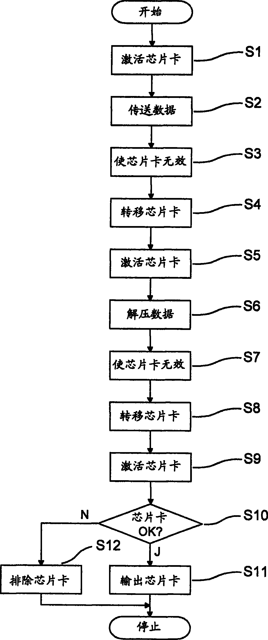
图3表示用来说明芯片卡通过图2所示的装置的通行过程的流程图, Fig. 3 represents the flow chart that is used to explain the passing process of chip card by the device shown in Fig. 2,
图4表示图3步骤S6可能的解压过程的原理图, Fig. 4 represents the schematic diagram of possible decompression process of Fig. 3 step S6,
图5表示本发明用来卡芯片模块初始化和/或个性化的装置的实施方式中的解压站的原理图, Fig. 5 shows the schematic diagram of the decompression station in the embodiment of the device used for card chip module initialization and/or personalization in the present invention,
图6表示与图5不同的解压站的原理图。 FIG. 6 shows a schematic diagram of a decompression station different from FIG. 5 . the
具体实施方式 Detailed ways
图1示出了芯片卡1的实施方式的极简化的方框图。芯片卡1具有控制芯片卡1功能运行并被称作中央处理器(简称CPU)的处理器单元2。此外,芯片卡1具有用于输入输出数据的接口3,其上连接着接触区4。可以提供用于无线信号传送的装置、如天线,来取代接触区4。此外,在所示出的实施方式中,芯片卡1包括由永久存储器6,非易失性存储器7,和易失性存储器8组成的存储器5。作为对此的替代,存储器5的其它结构也是可能的。处理器单元2是与接口3、永久存储器6、非易失性存储器7和易失性存储器8相连的。
FIG. 1 shows a very simplified block diagram of an embodiment of a
在永久存储器6中存入芯片卡1整个寿命内都被无改动地保存的数据。这里概念数据以下被用于泛指各种独立于其内容的信息,并且例如程序、参数、与个人有关的信息、密码等等都可归入其中。尤其是,将芯片卡1的操作系统存放在永久存储器6中。
In the
易失性存储器8用作处理器单元2的工作存储器,从而机密的数据比如 在进行计算的过程中被临时存储到易失性存储器8中。在易失性存储器8中的存储内容只能在芯片卡1被供电的情况下得以保存。
The
非易失性存储器7在芯片卡1整个寿命内都能重新被写入。即使芯片卡1不被供电,有关的存储内容也是得以保存的。在非易失性存储器7中存放例如操作系统的补充程序、应用软件、密码、与个人有关的信息等。
The
图2示出了根据本发明构造的用于芯片卡1初始化和/或个性化的装置9的实施方式的原理图。装置9包括加载站10和解压站11。与图2所示的不同,也可以作为两个单独的设备构造加载站10和解压站11。
FIG. 2 shows a schematic diagram of an embodiment of a
加载站10包括一系列的产品阅读器12。每个产品阅读器12可以与一个芯片卡1的接触区4接触,提供所有芯片卡1运行所需的供给信号,并把数据传送给芯片卡1。产品阅读器12分别表现为高价值的终端设备,并且例如可以根据预定的协议实施通信。与此对应地,产品阅读器12胜任的电子系统,例如按照微控制器的形式。供给信号可以特别是运行电压、接地、复位信号和时钟信号。
The
解压站11具有多个接触条(Kontaktierleiste)13,这些接触条分别拥有多个接触单元14用于与芯片卡1的接触区4接触。如以下还要进一步解释的那样,装置9具有比产品阅读器12更多的接触单元14。与产品阅读器12类似,通过接触单元14为芯片卡1输入运行所需的所有供给信号。未提供接触条13或者说接触单元14与芯片卡1的通信,这样接触条13和接触单元14的构造比产品阅读器12要简单得多,而只是把供给信号分配给各个芯片卡1。在一种具有优势的扩展中,接触单元14此外还与接在芯片卡1的接口13上的接触区4的区域相接触。不过,同样在该扩展中,没有进行与芯片卡1的通信,而只是输出芯片卡1的状态信息,并且例如通过一个未示出的发光二极管显示。同样在该扩展中,带有接触单元14的接触条13因此被构造得比产品阅读器12还要更为显著地简单。
The
在芯片卡1的通行方向,在解压站11之后设置了一个用于检查芯片卡1的检查设备15,可以将该检查设备按照与产品阅读器12相同的方式构造。
Arranged in the direction of travel of the
因此,在芯片卡1通过装置9的通行过程中,其依次经过加载站10、解压站11和检查设备15,并且在此被初始化和/或个性化。芯片卡1通过装置9的通行,将根据图作更详细的解释。
Thus, during the passage of the
图3示出了用来说明芯片卡1通过图2所示的装置9的通行过程的流程 图。以下以芯片卡1为例描述该通行。
Fig. 3 has shown the flow chart that is used for explaining the passing process of
流程图以步骤S1开始,芯片卡1在其中被激活。该激活是借助于通过一个产品阅读器12的接触而实现的。产品阅读器12为芯片卡1提供运行所需的供给信号。如从图2中可以看出的那样,装置9有很大数目的产品阅读器12,它们被平行地运行,使得很多数目的芯片卡1可被并行地激活。
The flow chart starts with step S1 in which the
接着步骤S1是步骤S2,在这一步骤中,将被压缩的数据传送到芯片卡1中,并且被存储到非易失性存储器7中。被压缩的数据可以是用于芯片卡1初始化的静态数据,也就是对多个芯片卡1相同的数据。此外,被压缩的数据也可包含卡片特有的数据。在本发明的关联中概念数据被用作为软件(例如,操作系统扩展或应用软件)以及信息的总称。数据被无损失的压缩,并且包含未被压缩前初始数据的所有信息内容。优选地,这样进行压缩,使得形成尽可能较高的压缩程度、即最大程度地减少数据量。对此适合的方法例如在Rechenberg,Pomberger的“Informatikhandbuch”,第2版,Carl Hanser出版社,慕尼黑,维也纳,1999中有描述。通过数据压缩实现了从产品阅读器12到芯片卡1的数据传送所需的时间缩短,并且实现芯片1在加载站10比在没有压缩的条件下更短的逗留时间。
Step S1 is followed by step S2 , in which the compressed data are transferred to the
在步骤S2之后执行步骤S3,在该步骤使芯片卡1无效。该无效可通过将芯片卡1从产品阅读器12上分离而实现。接着,在步骤S4中将芯片卡1从加载站10转移到解压站11。然后,在步骤S5中,在解压站11中芯片卡1被激活。芯片卡1的激活可借助于通过提供芯片卡1运行所需供给信号的接触单元14中的一个的接触来完成。
Step S3 is executed after step S2, in which the
步骤S5之后接着步骤S6,其中,将在步骤S2中传给芯片卡1的压缩数据解压。数据解压由芯片卡1中的处理器单元2完成,并占用比步骤S2中的传送时间明显更长的时间。与此对应地,解压站11的接受能力被设计得明显比加载站10的接受能力更高,从而保证了芯片卡1通过装置9的通行。换言之,接触单元14远多于产品阅读器12,使得在同一时间与加载站10中的芯片卡相比,明显更多的芯片卡1位于解压站11。
Step S5 is followed by step S6, in which the compressed data transmitted to the
除了解压数据之外,在步骤S6中将解压后的数据装入芯片卡1的非易失性存储器7中。在步骤S6中的具体过程将借助预图4描述。在步骤S6期间或者在步骤S6的末尾,将带有芯片卡1的接触条13朝向检查设备15的方向继续转移。
In addition to the decompressed data, the decompressed data are loaded into the
紧接着步骤S6,在步骤S7中使得芯片卡1无效。这可以通过将芯片卡1从接触单元14的分离来实现。随后,芯片卡1在步骤S8中被转移到检查设备15。之后接着的是步骤S9,在该步骤中芯片卡1被激活。这点尤其可以通过接触检查设备15的接触来完成。步骤S9之后执行步骤S10,在该步骤中,检查步骤S2中传送到芯片卡1的压缩数据是否在步骤S6中被正常解压并可以被安装。如果是这样,紧接着步骤S10的是步骤S11,在该步骤中芯片卡1被作为正常初始化和个性化而输出。否则的话,接着步骤S10是步骤S12,在该步骤中芯片卡1被认为有问题而被排除,并且安排再生产(Nachproduktion)。该流程图的运行随着步骤S11或者步骤S12而结束。
Following step S6, the
对所描述的过程的另一种优化可以如下地实现:在步骤S6中显示解压数据结束和通过芯片卡1的接口3的数据安装。以此为基础,可以将芯片卡1在解压站11的停留时间与目前条件相匹配,并由此使流程优化。
A further optimization of the described procedure can be realized as follows: In step S6 , the end of the unpacked data and the loading of the data via the
图4示出了对于图3的步骤S6可能的解压过程的原理图。左侧示出的方块表示了在步骤S2中从产品阅读器12到芯片卡1所传送的数据。这些数据被毫无改变地存入芯片卡1的非易失性存储器7中,并且包括用于解压和安装数据的软件模块、带有静态数据的方块和带有个人数据的方块。
FIG. 4 shows a schematic diagram of a possible decompression process for step S6 of FIG. 3 . The square shown on the left represents the data transferred from the
图4右侧分别示出了芯片卡1的易失性存储器8和非易失性存储器7的区域。通过不同的箭头表现出左侧示出的数据是如何被分配到右侧的存储器区域的。软件模块只在步骤6中解压和安装数据时需要一次,并且所以在步骤6开始时被复制到芯片卡1的易失性存储器8。之后,软件模块被运行并使芯片卡1的处理器单元2在整个芯片卡1的非易失性存储器7中搜索被压缩数据。在此,将按照这种方式确定的静态数据解压并复制到芯片卡1的非易失性存储器7中的预定的地址区域中。如果有的话,个人数据也被解压并被复制到芯片卡1的非易失性存储器7的特定存储位置。这点可以借助于在静态数据上所附的APDU命令实现。在此,APDU表示Application ProtocolData Unit(应用协议数据单元)。
The areas of the
优选地,在步骤S6结束时删除仅仅对于执行步骤S6必要的软件模块和必要时的其它数据,而这样被释放的存储器可以提供给操作系统或应用程序。图4中通过左侧不同大小的数据块和右侧示出的存储器区域表明,数据量通过解压而增加,并且由此比解压前需要更多的存储空间。 Preferably, at the end of step S6 only those software modules and possibly other data necessary for the execution of step S6 are deleted, while the memory thus freed can be made available to the operating system or application programs. The data blocks of different sizes on the left and the memory areas shown on the right in FIG. 4 show that the data volume increases through decompression and thus requires more storage space than before decompression. the
图5示出了本发明用于芯片模块初始化和/或个性化的装置9的实施方 式的解压站11的原理图。芯片模块尤其可被用来制造芯片卡1,并且通过接触区4提供给外部接触。芯片模块通过按照模块带16的形式通过机器,该模块带是由带状的支撑材料和设置在其上很大数量的芯片模块组成。加载站10被可以按照与图2中形式的装置9的实施方式类似地构造,并且包括多个产品阅读器12。
Figure 5 shows a schematic diagram of the
解压站11包括轮子17,在该轮子的圆周面积(Mantelfl
模块带16通过装置9的过程与图3的表示相对应,在此,只是芯片模块代替芯片卡1被初始化和/或个性化。在解压和在芯片模块上安装压缩数据期间的很长的逗留时间,在图5所示的实施方式中是通过轮子17实现的。通过选择轮子直径和转速可以规定供解压数据和安装数据使用的时间。如果要将该时间与实际情况相匹配的话,解压站11可以根据图6有所改动。
The passage of the
图6示出了与图5不同的解压站11的原理图。与图5不同的是,图6中模块带16没有包围轮子17,而是包围蚕形体19,在器外表面装有多个接触单元14。在此,导向辊18同样被用来引导模块带16的运行。蚕形体19被设计为外表面作循环式运动,因而带动模块带16运动。通过侧面移动蚕形体19相对于的导向辊18的位置,模块带16通过解压站11所经过的距离得以改变,并由此影响了芯片模块在解压站11中的停留时间。
FIG. 6 shows a schematic diagram of a
Claims (22)
Applications Claiming Priority (3)
| Application Number | Priority Date | Filing Date | Title |
|---|---|---|---|
| DE200510045149 DE102005045149A1 (en) | 2005-09-22 | 2005-09-22 | Method for initializing and / or personalizing a portable data carrier |
| DE102005045149.7 | 2005-09-22 | ||
| PCT/EP2006/008973 WO2007033792A2 (en) | 2005-09-22 | 2006-09-14 | Method for initialising and/or personalising a portable data carrier |
Publications (2)
| Publication Number | Publication Date |
|---|---|
| CN101326552A CN101326552A (en) | 2008-12-17 |
| CN101326552B true CN101326552B (en) | 2012-02-15 |
Family
ID=37852448
Family Applications (1)
| Application Number | Title | Priority Date | Filing Date |
|---|---|---|---|
| CN2006800350460A Expired - Fee Related CN101326552B (en) | 2005-09-22 | 2006-09-14 | Method for initialising and/or personalising a portable data carrier |
Country Status (4)
| Country | Link |
|---|---|
| EP (1) | EP1932122A2 (en) |
| CN (1) | CN101326552B (en) |
| DE (1) | DE102005045149A1 (en) |
| WO (1) | WO2007033792A2 (en) |
Families Citing this family (5)
| Publication number | Priority date | Publication date | Assignee | Title |
|---|---|---|---|---|
| DE102007053744A1 (en) | 2007-11-12 | 2009-05-14 | Giesecke & Devrient Gmbh | Method for loading initialization and / or personalization data onto a portable data carrier |
| DE102008052955B4 (en) * | 2008-10-23 | 2010-06-24 | Knorr-Bremse Systeme für Nutzfahrzeuge GmbH | Method for transmitting program codes to a memory of a control device, in particular for motor vehicles |
| DE102014000934B4 (en) | 2013-01-21 | 2022-12-01 | Giesecke+Devrient Mobile Security Gmbh | Flexible chip card holder |
| FR3028642B1 (en) * | 2014-11-13 | 2016-12-23 | Oberthur Technologies | METHOD FOR CUSTOMIZING A MICROCIRCUIT WITH WRITING A COMPRESSED PART OF SOFTWARE ENTITY, AND METHOD OF USE AND MICROCIRCUIT THEREFOR |
| DE102015207428A1 (en) * | 2015-04-23 | 2016-10-27 | Bundesdruckerei Gmbh | Method for compressing user data of a document |
Citations (8)
| Publication number | Priority date | Publication date | Assignee | Title |
|---|---|---|---|---|
| WO2000033266A1 (en) * | 1998-12-01 | 2000-06-08 | Gemplus | Chip card loadable with compressed data |
| WO2001041087A1 (en) * | 1999-12-04 | 2001-06-07 | Orga Kartensysteme Gmbh | Method for initialising and/or personalising chip cards and a corresponding device |
| WO2002075932A3 (en) * | 2001-03-21 | 2003-10-23 | Infineon Technologies Ag | Processor arrangement for security-related applications and method for carrying out security-related applications |
| CN1455897A (en) * | 2000-08-17 | 2003-11-12 | 三因迪斯克公司 | Multiple removable non-volatile memory cards serially communicating with host |
| EP1303154B1 (en) * | 1999-07-20 | 2004-09-15 | Siemens Aktiengesellschaft | Chip card and method for decompression and compression of received or sent data respectively |
| CN1537270A (en) * | 2001-08-02 | 2004-10-13 | 圣地斯克公司 | Detachable computer with large-capacity memory |
| WO2004107282A1 (en) * | 2003-06-03 | 2004-12-09 | Giesecke & Devrient Gmbh | Method for loading portable data carriers with data |
| DE102004005676A1 (en) * | 2004-02-05 | 2005-08-25 | Giesecke & Devrient Gmbh | Data carrier for execution of platform-independent program code has processor for executing the code and at least a partial interpreter for code interpretation that permits execution of at least partially compressed code |
Family Cites Families (4)
| Publication number | Priority date | Publication date | Assignee | Title |
|---|---|---|---|---|
| US4701600A (en) * | 1986-03-27 | 1987-10-20 | Data Card Corporation | System for entering initializing data on the rear face of an integrated chip card |
| JPH0196781A (en) * | 1987-10-09 | 1989-04-14 | Toshiba Corp | Processor for portable memory medium |
| US4774500A (en) * | 1987-10-21 | 1988-09-27 | Wright Technologies | Data compaction method for microprocessor cards |
| ATE317572T1 (en) * | 2000-08-17 | 2006-02-15 | Dexrad Pty Ltd | TRANSFER OF DATA FOR AUTHENTICITY CHECK |
-
2005
- 2005-09-22 DE DE200510045149 patent/DE102005045149A1/en not_active Ceased
-
2006
- 2006-09-14 WO PCT/EP2006/008973 patent/WO2007033792A2/en not_active Ceased
- 2006-09-14 CN CN2006800350460A patent/CN101326552B/en not_active Expired - Fee Related
- 2006-09-14 EP EP06792068A patent/EP1932122A2/en not_active Ceased
Patent Citations (8)
| Publication number | Priority date | Publication date | Assignee | Title |
|---|---|---|---|---|
| WO2000033266A1 (en) * | 1998-12-01 | 2000-06-08 | Gemplus | Chip card loadable with compressed data |
| EP1303154B1 (en) * | 1999-07-20 | 2004-09-15 | Siemens Aktiengesellschaft | Chip card and method for decompression and compression of received or sent data respectively |
| WO2001041087A1 (en) * | 1999-12-04 | 2001-06-07 | Orga Kartensysteme Gmbh | Method for initialising and/or personalising chip cards and a corresponding device |
| CN1455897A (en) * | 2000-08-17 | 2003-11-12 | 三因迪斯克公司 | Multiple removable non-volatile memory cards serially communicating with host |
| WO2002075932A3 (en) * | 2001-03-21 | 2003-10-23 | Infineon Technologies Ag | Processor arrangement for security-related applications and method for carrying out security-related applications |
| CN1537270A (en) * | 2001-08-02 | 2004-10-13 | 圣地斯克公司 | Detachable computer with large-capacity memory |
| WO2004107282A1 (en) * | 2003-06-03 | 2004-12-09 | Giesecke & Devrient Gmbh | Method for loading portable data carriers with data |
| DE102004005676A1 (en) * | 2004-02-05 | 2005-08-25 | Giesecke & Devrient Gmbh | Data carrier for execution of platform-independent program code has processor for executing the code and at least a partial interpreter for code interpretation that permits execution of at least partially compressed code |
Non-Patent Citations (1)
| Title |
|---|
| EP1303154B1B1 2004.09.15 |
Also Published As
| Publication number | Publication date |
|---|---|
| CN101326552A (en) | 2008-12-17 |
| WO2007033792A2 (en) | 2007-03-29 |
| DE102005045149A1 (en) | 2007-04-05 |
| EP1932122A2 (en) | 2008-06-18 |
| WO2007033792A3 (en) | 2007-08-23 |
Similar Documents
| Publication | Publication Date | Title |
|---|---|---|
| CN101965597B (en) | Method and device for installing and retrieving linked MIFARE applications | |
| US7689826B2 (en) | Flexibly loading a tamper resistant module | |
| US9158598B2 (en) | Apparatus, method, program and system for processing information utilizing a multi-platform capable of managing a plurality of applications | |
| US8544733B2 (en) | Method and apparatus for personalizing portable data storage media | |
| US20070067325A1 (en) | Methods and apparatus to load and run software programs in data collection devices | |
| US8931705B2 (en) | IC card, mobile electronic device and data processing method in IC card | |
| CN101326552B (en) | Method for initialising and/or personalising a portable data carrier | |
| US7136937B2 (en) | Contact and contactless interface storage device with processor | |
| US9449453B2 (en) | Portable electronic entity and method for personalization of such an electronic entity | |
| US20220350975A1 (en) | Ic card, ic card processing system, and computer-readable storage medium | |
| CN101479744B (en) | Method and apparatus for personalizing portable data storage media | |
| US9779347B2 (en) | Smart card and portable electronic apparatus | |
| US10509636B2 (en) | System, method and personalizable portable device in which application code libraries are distributed in a compressed form | |
| US20120234926A1 (en) | Portable electronic apparatus | |
| CN101706864B (en) | Method for identifying logical encryption card | |
| WO2009017292A1 (en) | Mobile status detection contactless module | |
| CN1635475A (en) | Data processing method between smart card with multi-application program and terminal | |
| CN102542226A (en) | Secure access implementation method applying terminal access intelligent card | |
| JP5202634B2 (en) | Mobile communication device and method for defragmenting MIFARE memory | |
| CN101533373B (en) | data access system | |
| HK1200963A1 (en) | An intelligent terminal into which financial ic cards are embeddable | |
| US20070124530A1 (en) | Portable electronic device and control method of portable electronic device | |
| CN107195081A (en) | The method of testing and device of financial transaction terminal, test card, computer-readable medium | |
| CN207216617U (en) | A kind of analogue system of card class chip | |
| KR20150074820A (en) | Security payment device including finance micro secure digital card and method of performing thereof |
Legal Events
| Date | Code | Title | Description |
|---|---|---|---|
| C06 | Publication | ||
| PB01 | Publication | ||
| C10 | Entry into substantive examination | ||
| SE01 | Entry into force of request for substantive examination | ||
| C14 | Grant of patent or utility model | ||
| GR01 | Patent grant | ||
| TR01 | Transfer of patent right |
Effective date of registration: 20180223 Address after: Munich, Germany Patentee after: Jiejia de mobile safety Co., Ltd. Address before: Munich, Germany Patentee before: Giesecke & Devrient GmbH |
|
| TR01 | Transfer of patent right | ||
| CF01 | Termination of patent right due to non-payment of annual fee |
Granted publication date: 20120215 Termination date: 20190914 |
|
| CF01 | Termination of patent right due to non-payment of annual fee |