CN101320794A - Anode and secondary battery - Google Patents
Anode and secondary battery Download PDFInfo
- Publication number
- CN101320794A CN101320794A CNA2008101098849A CN200810109884A CN101320794A CN 101320794 A CN101320794 A CN 101320794A CN A2008101098849 A CNA2008101098849 A CN A2008101098849A CN 200810109884 A CN200810109884 A CN 200810109884A CN 101320794 A CN101320794 A CN 101320794A
- Authority
- CN
- China
- Prior art keywords
- negative electrode
- active material
- electrode active
- secondary cell
- silicon
- Prior art date
- Legal status (The legal status is an assumption and is not a legal conclusion. Google has not performed a legal analysis and makes no representation as to the accuracy of the status listed.)
- Pending
Links
Images


Classifications
-
- H—ELECTRICITY
- H01—ELECTRIC ELEMENTS
- H01M—PROCESSES OR MEANS, e.g. BATTERIES, FOR THE DIRECT CONVERSION OF CHEMICAL ENERGY INTO ELECTRICAL ENERGY
- H01M4/00—Electrodes
- H01M4/02—Electrodes composed of, or comprising, active material
- H01M4/13—Electrodes for accumulators with non-aqueous electrolyte, e.g. for lithium-accumulators; Processes of manufacture thereof
- H01M4/134—Electrodes based on metals, Si or alloys
-
- H—ELECTRICITY
- H01—ELECTRIC ELEMENTS
- H01M—PROCESSES OR MEANS, e.g. BATTERIES, FOR THE DIRECT CONVERSION OF CHEMICAL ENERGY INTO ELECTRICAL ENERGY
- H01M10/00—Secondary cells; Manufacture thereof
- H01M10/05—Accumulators with non-aqueous electrolyte
- H01M10/052—Li-accumulators
- H01M10/0525—Rocking-chair batteries, i.e. batteries with lithium insertion or intercalation in both electrodes; Lithium-ion batteries
-
- H—ELECTRICITY
- H01—ELECTRIC ELEMENTS
- H01M—PROCESSES OR MEANS, e.g. BATTERIES, FOR THE DIRECT CONVERSION OF CHEMICAL ENERGY INTO ELECTRICAL ENERGY
- H01M4/00—Electrodes
- H01M4/02—Electrodes composed of, or comprising, active material
- H01M4/04—Processes of manufacture in general
- H01M4/0402—Methods of deposition of the material
- H01M4/0404—Methods of deposition of the material by coating on electrode collectors
-
- H—ELECTRICITY
- H01—ELECTRIC ELEMENTS
- H01M—PROCESSES OR MEANS, e.g. BATTERIES, FOR THE DIRECT CONVERSION OF CHEMICAL ENERGY INTO ELECTRICAL ENERGY
- H01M4/00—Electrodes
- H01M4/02—Electrodes composed of, or comprising, active material
- H01M4/04—Processes of manufacture in general
- H01M4/0438—Processes of manufacture in general by electrochemical processing
- H01M4/045—Electrochemical coating; Electrochemical impregnation
-
- H—ELECTRICITY
- H01—ELECTRIC ELEMENTS
- H01M—PROCESSES OR MEANS, e.g. BATTERIES, FOR THE DIRECT CONVERSION OF CHEMICAL ENERGY INTO ELECTRICAL ENERGY
- H01M4/00—Electrodes
- H01M4/02—Electrodes composed of, or comprising, active material
- H01M4/04—Processes of manufacture in general
- H01M4/049—Manufacturing of an active layer by chemical means
-
- H—ELECTRICITY
- H01—ELECTRIC ELEMENTS
- H01M—PROCESSES OR MEANS, e.g. BATTERIES, FOR THE DIRECT CONVERSION OF CHEMICAL ENERGY INTO ELECTRICAL ENERGY
- H01M4/00—Electrodes
- H01M4/02—Electrodes composed of, or comprising, active material
- H01M4/36—Selection of substances as active materials, active masses, active liquids
- H01M4/38—Selection of substances as active materials, active masses, active liquids of elements or alloys
- H01M4/386—Silicon or alloys based on silicon
-
- H—ELECTRICITY
- H01—ELECTRIC ELEMENTS
- H01M—PROCESSES OR MEANS, e.g. BATTERIES, FOR THE DIRECT CONVERSION OF CHEMICAL ENERGY INTO ELECTRICAL ENERGY
- H01M4/00—Electrodes
- H01M4/02—Electrodes composed of, or comprising, active material
- H01M2004/021—Physical characteristics, e.g. porosity, surface area
-
- H—ELECTRICITY
- H01—ELECTRIC ELEMENTS
- H01M—PROCESSES OR MEANS, e.g. BATTERIES, FOR THE DIRECT CONVERSION OF CHEMICAL ENERGY INTO ELECTRICAL ENERGY
- H01M2220/00—Batteries for particular applications
- H01M2220/30—Batteries in portable systems, e.g. mobile phone, laptop
-
- Y—GENERAL TAGGING OF NEW TECHNOLOGICAL DEVELOPMENTS; GENERAL TAGGING OF CROSS-SECTIONAL TECHNOLOGIES SPANNING OVER SEVERAL SECTIONS OF THE IPC; TECHNICAL SUBJECTS COVERED BY FORMER USPC CROSS-REFERENCE ART COLLECTIONS [XRACs] AND DIGESTS
- Y02—TECHNOLOGIES OR APPLICATIONS FOR MITIGATION OR ADAPTATION AGAINST CLIMATE CHANGE
- Y02E—REDUCTION OF GREENHOUSE GAS [GHG] EMISSIONS, RELATED TO ENERGY GENERATION, TRANSMISSION OR DISTRIBUTION
- Y02E60/00—Enabling technologies; Technologies with a potential or indirect contribution to GHG emissions mitigation
- Y02E60/10—Energy storage using batteries
Abstract
A battery capable of improving cycle characteristics is provided. An anode includes: an anode current collector, and an anode active material layer arranged on the anode current collector, in which the anode active material layer includes an anode active material including silicon (Si), and including a pore group with a diameter ranging from 3 nm to 50 nm both inclusive, and the volumetric capacity per unit weight of silicon of the pore group with a diameter ranging from 3 nm to 50 nm both inclusive is 0.2 cm3/g or less, the volumetric capacity being measured by mercury porosimetry using a mercury porosimeter.
Description
CROSS-REFERENCE TO RELATED APPLICATIONS
The present invention comprises the theme of following Japanese patent application, and promptly respectively on June 5th, 2007 with submitted to the JP 2007-149253 and the JP 2008-015253 of Japan Patent office on January 25th, 2008, its full content is incorporated herein by reference.
Technical field
The secondary cell that the present invention relates to negative pole and comprise this negative pole, described negative pole comprise negative electrode collector and the negative electrode active material layer that is arranged on the negative electrode collector.
Background technology
In recent years, portable electric appts such as the integrated VTR of camera (video tape recorder), portable phone or laptop computer are extensive use of, and people require to reduce the size and the weight of portable electric appts and the life-span of improving portable electric appts consumingly.Therefore, as the power supply of portable electric appts, people have managed to develop battery, the particularly lightweight secondary cell that can realize high-energy-density.In the middle of them, up-and-coming is to discharge and recharge reaction to utilize the embedding of lithium and the secondary cell of deviating from (so-called lithium rechargeable battery), because this secondary cell can obtain than lead-sour battery or the big energy density of nickel-cadmium cell.
Lithium rechargeable battery comprises positive pole, negative pole and electrolyte, and negative pole has the negative electrode active material layer that comprises negative electrode active material and is arranged in structure on the negative electrode collector.As negative electrode active material, be extensive use of material with carbon element; Yet recently along with the enhancing of portable electric appts performance and the expansion of function, people thirst for further improving battery capacity, therefore consider to replace material with carbon element with silicon.Because the theoretical capacity of silicon (4199mAh/g) is much larger than the theoretical capacity (372mAh/g) of graphite, expection can improve battery capacity.
Yet, when silicon is deposited as negative electrode active material by vapor phase method, in negative electrode active material, form a large amount of holes, increased the surface area of negative electrode active material.In this case, negative electrode active material has high activity, so electrolyte decomposes easily during discharging and recharging, and the easy passivation of lithium.Thereby when secondary cell obtained higher capacity, the key property-cycle characteristics of secondary cell but was easy to reduce.
Therefore, in order also to improve cycle characteristics with silicon during as negative electrode active material, people have proposed miscellaneous thoughts.
More specifically, following method has been proposed: by vapor phase method repeatedly under the situation of deposited silicon film,, ion is applied to the method (for example, opening the 2005-293899 communique) on the surface of silicon thin film referring to the spy in for the second time or before the deposition step more; Use has the method (for example, opening the 2004-071305 communique referring to the spy) of the negative electrode collector of three-dimensional structure such as foam metal or sintered fiber metallic object; Perhaps sinterable silicon makes method (for example, opening flat 11-339777 and 11-339778 communique referring to the spy) that itself and negative electrode collector become one etc.
And, following method has also been proposed: the method (for example, opening 2004-335334 and 2004-335335 communique) that coats silicon grain with sintered body (pottery) as metal oxide referring to the spy; Form the method (for example, opening the 2004-319469 communique) of oxide skin(coating) such as silicon oxide layer referring to the spy on the surface of silicon alloy layer; The method of reduce deposition conducting metal on silica flour (for example, opening flat 11-297311 communique) referring to the spy; Method (for example, opening the 2000-036323 communique) with metallic cover silicon compound particle referring to the spy; In silicon grain, disperse not form the method (for example, opening the 2001-273892 communique) of the metallic element of alloy referring to the spy with lithium; Copper is solid-solubilized in method (for example, opening 2002-289177 number) communique in the silicon thin film etc. referring to the spy.
Summary of the invention
Because recently portable electric appts has littler size, higher performance and more function, secondary cell will charge and discharge continually, thereby its cycle characteristics reduces easily.Particularly, adopt silicon as negative electrode active material with the lithium rechargeable battery that increases capacity in, cycle characteristics often reduces significantly because above-mentioned surface area increases.Therefore, people thirst for further improving the cycle characteristics of this secondary cell.
Because foregoing problems, expectation provides the negative pole and the secondary cell that can improve cycle characteristics.
According to embodiment of the present invention, a kind of negative pole is provided, this negative pole comprises: negative electrode collector; And be arranged in negative electrode active material layer on the negative electrode collector, wherein negative electrode active material layer comprises negative electrode active material, this negative electrode active material contains silicon, and to comprise diameter be 3~50nm and the group who comprises the hole of two end points (pore group), and by the silicon of per unit weight, this diameter is that the group's of 3~50nm and the hole that comprises two end points volume (volumetric capacity) is 0.2cm
3/ g or littler, this volume utilize the mercury porosimeter, measure by mercury porosimetry.
According to embodiment of the present invention, a kind of secondary cell is provided, this secondary cell comprises positive pole, negative pole and electrolyte, wherein said negative pole comprises negative electrode collector and the negative electrode active material layer that is arranged on the negative electrode collector, this negative electrode active material layer comprises negative electrode active material, this negative electrode active material contains silicon, and to comprise diameter be 3~50nm and the group who comprises the hole of two end points, and by the silicon of per unit weight, this diameter is that the group's of 3~50nm and the hole that comprises two end points volume is 0.2cm
3/ g or littler, this volume utilize the mercury porosimeter, measure by mercury porosimetry.
Above-mentioned " hole group volume " is the volume determination that replaces the group of fine pore by the intrusion amount with mercury, and the intrusion amount of described mercury is to utilize the mercury porosimeter, measure by mercury porosimetry.Thereby " diameter is the group's of 3~50nm and the hole that comprises two end points a volume " is by being the measurement total amount of the mercury in 3~50nm and the hole that comprises two end points with invasion diameter, replace having the same range as diameter hole group volume determination.And " diameter is the group's of 3~20nm and the hole that comprises two end points a volume " is by being the measurement total amount of the mercury in 3~20nm and the hole that comprises two end points with invasion diameter, replace having the same range as diameter hole group volume determination.The intrusion amount of mercury is to be respectively 485mN/m and 130 ° at the surface tension of mercury and contact angle, and the relation between pore diameter and the pressure is roughly the numerical value that records under the condition of 180/ pressure=diameter.The group's of the hole of Unit Weight silicon volume (cm
3/ g) can be by the weight (g) of silicon and the intrusion amount of the mercury (group's of=hole volume: cm
3) calculate.
In negative pole according to embodiments of the present invention, negative electrode active material comprises silicon, and to comprise diameter be 3~50nm and the group who comprises the hole of two end points, and by the silicon of per unit weight, diameter is that the group's of 3~50nm and the hole that comprises two end points volume is 0.2cm
3/ g or littler, it is to utilize the mercury porosimeter, measures by mercury porosimetry, so, the situation that exceeds this scope with volume is compared, even negative electrode active material comprises the silicon with high response, this negative electrode active material is still resisted with other material and reacted.Thereby in secondary cell according to embodiments of the present invention, the electrolyte opposing is decomposed during discharging and recharging, thereby can improve cycle characteristics.In this case, when the diameter by Unit Weight silicon be 3~50nm and the hole that comprises two end points group volume be 0.05cm
3/ g or littler is 0cm more specifically
3During/g, can obtain better effect.
And, when the diameter by Unit Weight silicon be 3~20nm and the hole that comprises two end points group volume (utilizing the mercury porosimeter to measure) by mercury porosimetry be 0.2cm
3/ g or more hour can obtain better effect.In this case, be that the group's of 3~20nm and the hole that comprises two end points volume is 0.05cm by the diameter of Unit Weight silicon
3/ g or littler perhaps is 0cm more specifically
3During/g, can obtain better effect.
In addition, when comprising oxidiferous film in the hole or not forming the metal material of alloy with the electrode reaction thing, even the volume the group of the hole of per unit weight silicon exceeded under the situation of above-mentioned scope originally, also easily the group's of the hole of per unit weight silicon volume is adjusted in this scope.In this case, if oxidiferous film forms by liquid phase method such as liquid phase deposition, perhaps metal material forms by liquid phase method such as electrolytic plating method (electrolytic plating method), then oxidiferous film or metal material invade in the hole easily, so can obtain better effect.
When negative electrode active material comprises oxygen, and the oxygen content in the negative electrode active material is 3~40at% and when comprising two end points, perhaps when negative electrode active material comprises the metallic element of at least a chosen from Fe, cobalt, nickel, titanium, chromium and molybdenum, perhaps contain the oxygen district when (comprising the zone that oxygen and its oxygen content are higher than other zone), can obtain better effect when anode active material particles comprises along its thickness direction.
When 10 mean roughness in the surface of negative electrode collector (ten-point height of roughnessprofile) Rz is 1.5~6.5 μ m and when comprising two end points, can obtain better effect.
By following explanation, of the present invention other and further purpose, feature and advantage will be more comprehensive.
Description of drawings
Fig. 1 is the sectional view of negative pole structure according to embodiments of the present invention;
Fig. 2 A and 2B are the SEM photo and the schematic diagrames of the cross-sectional configuration of negative pole shown in Figure 1;
Fig. 3 is the chart that the rate of change of mercury intrusion amount distributes;
Fig. 4 A and 4B are the SEM photo and the schematic diagrames of another cross-sectional configuration of negative pole shown in Figure 1;
Fig. 5 comprises the sectional view of first secondary cell structure of negative pole according to embodiments of the present invention;
Fig. 6 is the sectional view along first secondary cell of the VI-VI line intercepting of Fig. 5;
Fig. 7 comprises the sectional view of second secondary cell of negative pole according to embodiments of the present invention;
Fig. 8 is the sectional view of the amplification of spiral winding electrode part shown in Figure 7;
Fig. 9 comprises the sectional view of the structure of the 3rd secondary cell of negative pole according to embodiments of the present invention;
Figure 10 is the sectional view along the spiral winding electrode of the X-X line intercepting of Fig. 9;
Figure 11 is the curve chart of correlation between volume and the discharge capacitance;
Figure 12 is the curve chart of another correlation between volume and the discharge capacitance;
Figure 13 is the curve chart of correlation between oxygen content and the discharge capacitance; And
Figure 14 is the curve chart of correlation between 10 mean roughness and the discharge capacitance.
Embodiment
Embodiment preferred is described in detail in detail below with reference to accompanying drawings.
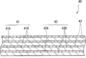
Fig. 1 shows the sectional view of negative pole according to embodiments of the present invention.Negative pole is used for, and for example, in electrochemical appliance such as the secondary cell, and comprises the negative electrode collector 1 with a pair of surface, and is arranged in the negative electrode active material layer 2 on the negative electrode collector 1.
Preferred negative electrode current collector 1 is made by the metal material with good electrical chemical stability, conductivity and mechanical strength.The example of metal material comprises copper, nickel, stainless steel etc.In the middle of them, preferably copper is because can obtain high conductivity.
Particularly, as the metal material of preparation negative electrode collector 1, preferably comprise a kind of, two or more do not form the metal material of the metallic element of intermetallic compound with the electrode reaction thing.When metallic element and electrode reaction thing formation intermetallic compound, because of electrochemical appliance duration of work (for example secondary cell discharge and recharge during) expansion of negative electrode active material layer 2 and the influence that contraction causes, can cause the reduction of current collection or negative electrode active material layer 2 to peel off with negative electrode collector 1.The example of metallic element comprises copper, nickel, titanium, iron, chromium etc.
And the metallic element that preferred above-mentioned metal material comprises is a kind of, two or more and negative electrode active material layer 2 form alloys.Because can improve the adhesive force between negative electrode collector 1 and the negative electrode active material layer 2 like this, make that negative electrode active material layer 2 is not easy to peel off with negative electrode collector 1.When negative electrode active material layer 2 comprises silicon as negative electrode active material, do not form intermetallic compound but comprise copper, nickel, iron etc. with example that negative electrode active material layer 2 forms the metallic element of alloys with the electrode reaction thing.With regard to intensity and conductivity, these metallic elements are preferred.
The surface of preferred negative electrode current collector 1 is coarse.Because can improve adhesive force between negative electrode collector 1 and the negative electrode active material layer 2 by so-called grappling effect.In this case, be coarse towards the surface of the negative electrode active material layer 2 of negative electrode collector 1 at least.As the method for roughening, for example, can mention by fine grain methods of formation such as electrolytic treatments.Electrolytic treatments is the method that forms fine particle and then formation rough surface in electrolysis tank by electrolysis on the surface of negative electrode collector 1.Copper Foil so-called " electrolytic copper foil " through electrolytic treatments.
10 the mean roughness Rz in the surface of preferred negative electrode current collector 1 are 1.5~6.5 μ m and comprise two end points.Because can improve the adhesive force between negative electrode collector 1 and the negative electrode active material layer 2 so further.More specifically,, may not can obtain enough adhesive force, and as 10 mean roughness Rz during greater than 6.5 μ m, negative electrode active material can comprise a large amount of holes, and its surface area is increased as 10 mean roughness Rz during less than 1.5 μ m.
Negative electrode active material layer 2 comprises the negative electrode active material that can embed and deviate from the electrode reaction thing.Negative electrode active material comprises element silicon.Because silicon embeds and deviates from the capacity height of electrode reaction thing, so can obtain high-energy-density.And negative electrode active material comprises a plurality of holes, so the distribution of the diameter range of these a plurality of holes is very wide, from about several nm to thousands of nm.When having group's (hereafter is " group of fine pore ") of hole of minor diameter scope of the 3~50nm that comprises two end points in the middle of paying close attention to them, the group's of the fine pore of per unit weight silicon volume (utilizing the mercury porosimeter to measure by mercury porosimetry) is 0.2cm
3/ g or littler.This is because reduce the group's of fine pore volume, and the surface area of negative electrode active material is controlled to less, so even have under the highly active situation at negative electrode active material, negative electrode active material also reacts with other material hardly.As described other material, for example, can mention the electrolyte when negative pole is used for secondary cell.
The group's of above-mentioned fine pore volume is by the group's who replaces the fine pore with the intrusion amount of mercury volume determination, the intrusion amount of described mercury utilizes the mercury porosimeter to measure by mercury porosimetry, and the intrusion amount of this mercury is to be respectively 485mN/m and 130 ° at mercury surface tension and contact angle, and the relation between pore diameter and the pressure is roughly the measured value under the condition of 180/ pressure=diameter.By this method, under the situation of the diameter distribution broad of a plurality of holes, therefore can measure the volume (invading the amount of mercury in the hole) of each concrete diameter range mesopore, can be the amount of mercury (group's of fine pore total measurement (volume): cm in 3~50nm and the hole that comprises two end points by the total weight (g) of silicon and the measured diameter that invades
3), the group's of the fine pore of mensuration per unit weight silicon above-mentioned volume (cm
3/ g).Adopting diameter when the group's of definition per unit weight silicon fine pore volume scope is 3~50nm and the hole that comprises two end points, its reason is, because the volume of each hole is very little, but the sum of hole is but very big, so the surface area effect of this hole anticathode active material is big.
Particularly, preferred per unit weight silicon diameter is that the group's of 3~50nm and the fine pore that comprises two end points volume is 0.05cm
3/ g or littler, more preferably 0cm
3/ g is because can obtain better effect.Clearly, the group's of fine pore volume is measured by the mercury porosimeter, and the group's of fine pore volume is 0cm
3/ g mean the measurement result of mercury porosimeter be the fine pore group volume be 0cm
3/ g (promptly can't measure the group's of fine pore volume).
In this case, at diameter is among the group of 3~50nm and the fine pore that comprises two end points, when paying close attention to the group that diameter is 3~20nm and the very small pores that comprises two end points (hereinafter being referred to as " group of very small pores "), utilize the mercury porosimeter to be preferably 0.2cm by the group's of the per unit weight silicon very small pores of mercury porosimetry measurement volume
3/ g or littler, more preferably 0.05cm
3/ g or littler most preferably is 0cm
3/ g.Because the influence of the group's of very small pores volume anticathode active material surface area is big among the group of fine pore, so can obtain better effect.
When needing, negative electrode active material layer 2 can comprise oxidiferous film or not with the fine pore in the electrode reaction thing form the metal material of alloy so that the group's of the fine pore of per unit weight silicon volume is in above-mentioned scope.Because when oxidiferous film or metal material intrusion fine pore, the group's of fine pore volume reduces.In this case, when the fine pore was full of oxidiferous film or metal material fully, the group's of the fine pore of per unit weight silicon volume can be 0cm
3/ g.
Oxidiferous film comprises, for example, and the oxide of the oxide of at least a oxide that is selected from silicon, germanium and the oxide of tin.Except them, oxidiferous film can also comprise any other oxide.Oxidiferous film can form by the arbitrary method in vapor phase method and the liquid phase method.In the middle of them, preferred liquid phase method such as liquid phase deposition, sol-gel process, rubbing method or dip coating, in the middle of these liquid phase methods, more preferably liquid phase deposition is because oxidiferous film invades in the fine pore easily.
As the metal material that invades in the fine pore, for example, can mention comprising the metal material that does not form the metallic element of alloy with the electrode reaction thing, and, for example, can mention the element of at least a chosen from Fe, cobalt, nickel, zinc and copper.In addition, metal material can also comprise any other metallic element.The form of metal material is not limited to simple substance, and metal material can be alloy or metallic compound.Metal material can form by the arbitrary method in vapor phase method or the liquid phase method.In the middle of them, preferred liquid phase method such as electrolytic plating method or electroless plating method, more preferably electrolytic plating method because metal material invades in the fine pore easily, and only needs the short plating time.When negative electrode active material layer 2 comprised metal material, this metal material served as binding agent, so can improve the caking property in the negative electrode active material.
Negative electrode active material layer 2 can only comprise a kind of in oxidiferous film and the metal material, also can comprise the two.During a kind of in the middle of including only them, preferably comprise oxidiferous film.Because by the oxidiferous film of liquid phase method such as liquid phase deposition formation, than easier the invading in the fine pore of metal material that forms by liquid phase method such as electrolytic plating method.
Negative electrode active material can be simple substance, alloy or the compound of silicon, or comprises a kind of, the negative electrode active material of two or more in the middle of them in mutually to small part.Can only use a kind of in the middle of them, also can use the multiple mixture that is selected from the middle of their.
In the present invention, described alloy also comprises the alloy that contains one or more metallic elements and one or more metalloid elements except the alloy that comprises two or more metallic elements.In addition, in the present invention, described alloy can comprise nonmetalloid.As the metallographic structure of alloy, can mention solid solution, eutectic (eutectic mixture), intermetallic compound or be selected from two or more coexistences among them.
As the alloy of silicon, for example, can mention except silicon, also comprising being selected from tin (Sn) nickel, copper, iron, cobalt, manganese (Mn), zinc, indium (In), silver (Ag), titanium, germanium (Ge), bismuth (Bi), the alloy of at least a element in antimony (Sb) and the chromium.
As the compound of silicon, for example, can mention the compound that except silicon, also comprises oxygen or carbon (C) element.For example, the compound of silicon can also comprise the element described in a kind of alloy of, two or more above-mentioned silicon except silicon.
Negative electrode active material is attached on the negative electrode collector 1, and along the superficial growth from negative electrode collector 1 of the thickness direction of negative electrode active material layer 2.In this case, negative electrode active material is to form by vapor phase method, and as mentioned above, preferred negative electrode current collector 1 and negative electrode active material layer 2 betwixt to the small part interface, form alloy.More specifically, the element of negative electrode collector 1 can be spread in the interface of negative electrode active material layer 2, and perhaps the element of negative electrode active material layer 2 can be spread in the interface of negative electrode collector 1, and perhaps they can be spread in each other the interface.Owing to be difficult to make negative electrode active material layer 2 fragmentations, so can improve the electron conduction between negative electrode collector 1 and the negative electrode active material layer 2 because of its expansion and contraction in electrode reaction.
As above-mentioned vapor phase method, for example, can mention physical deposition method or chemical deposition, particularly vacuum deposition method, sputtering method, ion plating method, laser ablation method, hot CVD (chemical vapour deposition (CVD)) method, plasma chemical vapor deposition etc.
And negative electrode active material can be the form of a plurality of particles.Negative electrode active material can form to have monolayer constructions will by a deposition step, also can form to have multi-ply construction in particle by a plurality of deposition steps.Yet, when negative electrode active material when forming with the evaporation of high heat between depositional stage, do not suffer heat damage in order to make negative electrode collector 1, preferred negative electrode active material has multi-ply construction.Because when the step of deposition negative electrode active material is divided into several times when carrying out (negative electrode active material forms deposition in succession), compare with the situation that deposition step only carries out once, negative electrode collector 1 has been exposed to high hot time decreased.
Particularly, preferred negative electrode active material comprises oxygen element.Because can prevent the expansion and the contraction of negative electrode active material layer 2.In negative electrode active material layer 2, partial oxygen combines with part silicon at least.In this case, the combination between oxygen and the silicon can be in the state of silicon monoxide or silicon dioxide, perhaps is in any other metastable condition.
Oxygen content in the preferred negative electrode active material is 3~40at% and comprises two end points, because can obtain better effect.More specifically, when oxygen content during less than 3at%, existence can not fully prevent the possibility that negative electrode active material layer 2 expands and shrinks, and when oxygen content during greater than 40at%, exists resistance to increase too many possibility.When negative pole and electrolyte one were used from electrochemical appliance, the coating that is decomposed to form by electrolyte was not included in the negative electrode active material.In other words, when the oxygen content in definite negative electrode active material by calculating, do not comprise the oxygen in the above-mentioned coating.
For example, when forming negative electrode active material by vapor phase method, oxygen containing negative electrode active material can form in chamber by introducing oxygen continuously.Particularly, when only when introducing oxygen needed oxygen content can not be obtained, can in chamber, introduce the source of supply of liquid (as steam etc.) as oxygen.
And preferred negative electrode active material comprises the metallic element of at least a chosen from Fe, cobalt, nickel, titanium, chromium and molybdenum.Because can improve the caking property in the negative electrode active material, stop the expansion and the contraction of negative electrode active material layer 2, and reduce the resistance of negative electrode active material.The content of metallic element in negative electrode active material can arbitrarily be provided with.Yet, be used at this negative pole under the situation of secondary cell, when the content of metallic element is too big, in order to obtain required battery capacity, need to increase the thickness of negative electrode active material layer 2, so negative electrode active material layer 2 can be peeled off from negative electrode collector 1, perhaps negative electrode active material layer 2 can break.
When negative electrode active material formed by the evaporation as vapor phase method, the negative electrode active material that comprises above-mentioned metallic element can utilize the evaporation source or the multicomponent evaporation source that wherein are mixed with metallic element to form.
Negative electrode active material comprises along the oxygen containing oxygen district that contains of its thickness direction bag, and the oxygen content that preferably contains the oxygen district is higher than other the regional oxygen content except that this contains the oxygen district.Because can prevent the expansion and the contraction of negative electrode active material layer 2.Other zone except that containing the oxygen district can contain oxygen also can oxygen-free.When other zone except that containing the oxygen district comprised oxygen, other the regional oxygen content except that this contains the oxygen district was lower than the oxygen content that this contains the oxygen district.
In this case, for expansion and the contraction that stops negative electrode active material layer 2, preferably other zone except that containing the oxygen district comprises oxygen, and negative electrode active material comprises that first contains oxygen district (having the zone than low oxygen content) and oxygen content and be higher than first and contain second of oxygen district and contain oxygen district (zone with higher oxygen content).In this case, preferred second contains the oxygen district is clipped in first and contains in the middle of the oxygen district, and more preferably first contains oxygen district and second to contain the oxygen district alternately laminated.Because can obtain better effect.Preferred first to contain the oxygen content in oxygen district low as much as possible, for example, and the oxygen content when second oxygen content that contains the oxygen district equals above-mentioned substance and comprises oxygen.
Comprise that first and second negative electrode active materials that contain the oxygen district can form by introducing oxygen off and on to chamber, also can be when for example vapor phase method form negative electrode active material, the amount of oxygen that is incorporated in the chamber by change forms.Only can not obtain under the situation of needed oxygen content, can in chamber, introduce liquid (for example steam etc.) by introducing oxygen.
First and second oxygen contents that contain in the oxygen district can be also can not be visibly different each other.Particularly, under the situation that the introducing amount of above-mentioned oxygen continuously changes, oxygen content also can change continuously.Under the situation that the introducing amount of oxygen intermittently changes, first and second contain the oxygen district promptly becomes so-called " floor (layer) ", and under the situation that the introducing amount of oxygen continuously changes, first and second contain the oxygen district promptly becomes " lamination (laminar) " rather than " floor ".Under latter event, the oxygen content height in the negative electrode active material distributes repeatedly.In this case, preferred oxygen content contains between the oxygen district progressively or changes continuously first and second.When oxygen content changed rapidly, ions diffusion can descend, and perhaps resistance can increase.
Referring to Fig. 2 A and 2B to 4A and 4B, the concrete structure example of the negative pole the when particle that will describe the graininess negative electrode active material below has multi-ply construction.Fig. 2 A, 2B, 4A and 4B show the sectional view of the amplification of negative pole, and Fig. 2 A and 4A show scanning electron microscopy (SEM) photo (secondary electron image), and Fig. 2 B and 4B show the schematic diagram of SEM photo shown in Fig. 2 A and the 4A respectively.Fig. 3 shows the distribution of mercury intrusion amount rate of change.
As shown in Figure 2A and 2B, comprise that at negative electrode active material under the situation of a plurality of particles (anode active material particles 201), negative electrode active material comprises a plurality of holes 202.More specifically, at the roughened surface of negative electrode collector 1, there are a plurality of projections (for example particulate that forms by electrolytic treatments).In this case, negative electrode active material repeatedly deposits and is laminated on the surface of negative electrode collector 1 by vapor phase method etc., and then progressively forms anode active material particles 201 along thickness direction on above-mentioned each projection.Because this closs packing structure of a plurality of anode active material particles 201, multi-ply construction and surface structure are so form a plurality of holes 202.
When invading amount of mercury V in the hole 202 simultaneously again during increase pressure P in each stage by the measurement of mercury porosimeter, the distribution of the rate of change of mercury intrusion amount (Δ V/ Δ P) as shown in Figure 3.In Fig. 3, transverse axis is represented the diameter (nm) of hole 202, and the longitudinal axis represents to invade the rate of change of the amount of mercury in the hole 202.The rate of change of mercury intrusion amount so distributes, and makes to have two peak P1 and P2 in the diameter range of the 3~3000nm that comprises two end points, and described diameter is measured by the mercury porosimeter.The peak P1 that is positioned at wide diameter one side mainly is that the existence owing to hole 202A forms, and the distribution of diameter is the 50~3000nm that comprises two end points.On the other hand, the peak P2 that is positioned at narrow diameter one side mainly is that the existence owing to hole 202B and 202C forms, and the distribution of diameter is the 3~50nm that comprises two end points.The rate of change of the mercury intrusion amount on Fig. 3 longitudinal axis is that the rate of change (being the maximum that rate of change is comprising 50~3000nm diameter range of two end points) at peak P1 is the normalized value under 1 the condition.
As shown in Figure 4A and 4B, after forming a plurality of anode active material particles 201,, metal material 203 is invaded in the hole 202 by formation metal materials 203 such as electrolytic plating methods.That is to say, make metal material 203 invade gap (hole 202A) between the adjacent cathode active material particle 201, be formed at the gap (hole 202B) between anode active material particles 201 lip-deep Xiao Hu's stubble shape projections, and in the gap (hole 202C) in the anode active material particles 201.In Fig. 4 A and 4B, spot distribution metal material 203 around anode active material particles 202 surfaces in outermost layer means that above-mentioned little projection is present in the position that is scattered with metal material 203.
As shown in Fig. 2 A and 2B to 4A and 4B, when having multi-ply construction in the particle of granular negative electrode active material, above-mentioned fine pore comprise hole 202B and 202C the two.In this case, just for the group's of fine pore that per unit weight silicon is set volume in above-mentioned scope, metal material 203 can include only hole 202B and 202C; Yet, consider the performance of whole negative pole, preferred metal materials 203 invades among the hole 202A, and more preferably hole 202A is full of by metal material 203.Because metal material 203 can improve the caking property in the negative electrode active material, and difficult expansion and the contraction that negative electrode active material layer 2 takes place.
In the particle of granular negative electrode active material, do not have under the situation of multi-ply construction (having only monolayer constructions will), do not form hole 202C, so the fine pore only comprises hole 202B.
Although reference accompanying drawing does not herein provide specific description, but forming oxidiferous film under the situation of nonmetallic materials by liquid phase deposition etc., oxidiferous film is along the superficial growth of anode active material particles 201, so oxidiferous film preferentially invades among hole 202B and the 202C.In this case, when sedimentation time increased, oxidiferous film just invaded among the hole 202A.
For instance, negative pole prepares through the following steps.
At first, after preparation negative electrode collector 1, according to the surface that needs roughened negative electrode collector 1.Secondly, by vapor phase method etc. make siliceous deposits on negative electrode collector 1 to form negative electrode active material.When forming negative electrode active material, negative electrode active material can form to have monolayer constructions will by a deposition step, and perhaps negative electrode active material also can form to have multi-ply construction by a plurality of deposition steps.When negative electrode active material has multi-ply construction by vapor phase method formation, can be when moving forward and backward negative electrode collector 1 with respect to evaporation source depositing silicon repeatedly, also can open and close gate (shutter) simultaneously repeatedly with respect to the fixing depositing silicon repeatedly in the negative electrode collector 1 of evaporation source.Can by liquid phase method etc. form oxidiferous film or with electrode reaction thing do not form the metal material of alloy thereafter.Forming by liquid phase deposition under the situation of oxidiferous film, in as the fluoro complex solution of silicon, add and mix easily with the dissolved matter of fluorine coordination as anionic trapping agent with the formation mixture after, the negative electrode collector 1 that is formed with negative electrode active material on it is dipped in this mixture, catch the fluorine anion that fluoro complex produces by this dissolved matter then, and then at the surface deposition oxide of negative electrode active material.In this case, can use the replacement fluoro complex such as compound of the silicon that produces other anion such as sulfate ion.Thereby, form negative electrode active material layer 2, and then finish negative pole.
In negative pole, negative electrode active material comprises silicon, and have group's (diameter is 3~50nm and the group who comprises the hole of two end points) of fine pore, and utilize the mercury porosimeter to be 0.2cm by the group's of the fine pore of the per unit weight silicon of mercury porosimetry measurement volume
3/ g or littler, thereby compare with the situation that volume exceeds this scope, even comprise under the situation with highly active silicon at negative electrode active material, this negative electrode active material is also resisted with other material and is reacted.Therefore, this negative electrode active material can help to improve the cycle characteristics of the electrochemical appliance that adopts this negative pole.In this case, the volume as the group of the fine pore of per unit weight silicon is 0.05cm
3/ g or littler perhaps more specifically is 0cm
3During/g, can obtain better effect.
Particularly, when utilizing the mercury porosimeter to count 0.2cm by the silicon of per unit weight by the volume of group (diameter is the group of 3~20nm and the hole that comprises two end points) of the very small pores of mercury porosimetry measurement
3/ g or more hour can obtain better effect.In this case, the volume as the group of the very small pores of per unit weight silicon is 0.05cm
3/ g or littler perhaps is 0cm more specifically
3During/g, can obtain better effect.
And, when comprising oxidiferous film in the fine pore or not forming the metal material of alloy with the electrode reaction thing, even the group's of the fine pore of per unit weight silicon volume exceeds above-mentioned scope, the group's of the fine pore of per unit weight silicon volume also is adjusted in this scope easily.In this case, when forming oxidiferous film by liquid phase method such as liquid phase deposition, when perhaps forming metal material by liquid phase method such as electrolytic plating method, oxidiferous film or metal material invade in the fine pore easily, so can obtain better effect.
In addition, when negative electrode active material comprises oxygen, and the oxygen content in the negative electrode active material is 3~40at% and when comprising two end points, perhaps when negative electrode active material comprises the metallic element of at least a chosen from Fe, cobalt, nickel, titanium, chromium and molybdenum, perhaps, anode active material particles can obtain better effect when containing oxygen district (oxygen content wherein be higher than other regional oxygen content of removing outside this zone contain the oxygen zone) when comprising along its thickness direction.
When the surface of facing with the negative electrode active material layer 2 of negative electrode collector 1 forms particulate by electrolytic treatments and during roughening, can improve the adhesive force between negative electrode collector 1 and the negative electrode active material layer 2.In this case, when 10 the mean roughness Rz in the surface of negative electrode collector 1 are 1.5~6.5 μ m and when comprising two end points, can obtain better effect.
Next, the application example of above-mentioned negative pole will be described below.As the example of electrochemical appliance, use secondary cell, and this negative pole to be applied to secondary cell as follows.
(first secondary cell)
Fig. 5 and 6 shows the sectional view of first secondary cell, and Fig. 6 shows along the sectional view of the VI-VI line intercepting of Fig. 5.Secondary cell described herein is, for example, lithium rechargeable battery, wherein the capacity of negative pole 22 is with as the embedding of the lithium of electrode reaction thing with take off expression.
Secondary cell comprise be in the battery case 11 have flattened roll around the structure battery unit 20.
And battery case 11 is for having the hollow structure of openend and blind end, and insulation board 12 and battery cover 13 are connected openend and sealed cell shell 11.Insulation board 12 is arranged between battery unit 20 and the battery cover 13 along the direction perpendicular to battery unit 20 peripheral coiling surfaces, insulation board 12 be by, for example, polypropylene etc. are made.Battery cover 13 be by, for example, make with battery case 11 identical materials, and can serve as electrode terminal by identical mode.
The end plate 14 that becomes positive terminal is arranged in the outside of battery cover 13, and end plate 14 is by insulating case 16 and battery cover 13 electric insulations.Insulating case 16 be by, for example, polybutylene terephthalate (PBT) etc. are made.And, near battery cover 13 central authorities, being furnished with through hole, anodal pin one 5 inserts in the through holes, so that is electrically connected with end plate 14 and by packing ring 17 and battery cover 13 electric insulations.Packing ring 17 be by, for example, insulating material is made, and its surface is covered with pitch.
That positive active material comprises is a kind of, two or more can embed and deviate from the positive electrode as the lithium of electrode reaction thing.As this positive electrode, for example, can mention lithium and cobalt oxides, lithium nickel oxide comprises the solid solution (Li (Ni of lithium and cobalt oxides and lithium nickel oxide
xCo
yMn
z) O
2, wherein the numerical value of x, y and z is 0<x<1,0<y<1 and 0<z<1, and x+y+z=1), lithium composite xoide is as having the lithium manganese oxide (LiMn of spinel structure
2O
4) or its solid solution (Li (Mn
2-vNi
v) O
4, wherein the numerical value of v is v<2) etc.And, as this positive electrode, for example, can also mention phosphate compounds such as iron lithium phosphate (LiFePO with olivine structural
4).Because can obtain high-energy-density.Except that above-mentioned material, this positive electrode can also for, for example, oxide such as titanium oxide, vanadium oxide or manganese dioxide, disulphide such as ferrous disulfide, titanium disulfide or molybdenum bisuphide, sulphur, perhaps conducting polymer such as polyaniline or polythiophene.
Dividing plate 23 be isolated in anodal 21 with negative pole 22 between so that the ion of electrode reaction thing therefrom through and stop the short circuit current that causes because of positive pole 21 and contacting of negative pole 22.Dividing plate 23 be by, for example, such as the perforated membrane of synthetic resin such as polytetrafluoroethylene, polypropylene or polyethylene, porous ceramic film etc. are made, and dividing plate 23 can have wherein two or more porous membrane laminated structures.
Dividing plate 23 is impregnated with the electrolyte as liquid electrolyte.Electrolyte comprises solvent and the electrolytic salt that is dissolved in the solvent.
Described solvent comprises, for example, and a kind of, two or more nonaqueous solventss such as organic solvent etc.This examples of non-aqueous comprises carbonates solvent such as ethylene carbonate ester, propylene glycol carbonate, carbonic acid butanediol ester, dimethyl carbonate, diethyl carbonate, methyl ethyl carbonate and carbonic acid first propyl ester.Because can obtain excellent capacity characteristic, storage characteristic and cycle characteristics.A kind of in them can be only used, also mixture multiple in them can be used.In the middle of them, as solvent, the mixture of preferred high viscosity solvent such as ethylene carbonate ester or propylene glycol carbonate and low viscosity solvent such as dimethyl carbonate, methyl ethyl carbonate or diethyl carbonate.Because can improve the dissociating property and the ion transport of electrolytic salt like this, and then obtain better effect.
And preferred solvent comprises the carbonic ester of halo.Because can form stable coating on the surface of negative pole 22 like this, stop electrolyte decomposition, and then improve cycle characteristics.As the carbonic ester of this halo, the carbonic ester of preferred fluorinated, preferred especially difluorizated ethylene carbonate ester is because can obtain better effect.As difluorizated ethylene carbonate ester, for example, can mention 4,5-two fluoro-1,3-dioxolanes-2-ketone etc.
In addition, preferred solvent comprises the cyclic carbonate that contains unsaturated bond, because can improve cycle characteristics.The example that contains the cyclic carbonate of unsaturated bond comprises carbonic acid ethenylidene ester, vinyl ethylene carbonate ester etc., and can use their mixture.
And preferred solvent comprises sultone.Because can improve cycle characteristics like this, and the expansion of prevention secondary cell.The example of sultone comprises 1,3-propylidene sultone (1,3-propene sultone) etc.
Electrolytic salt comprises a kind of, two or more light metal salt such as lithium salts.The example of lithium salts comprises lithium hexafluoro phosphate (LiPF
6), lithium perchlorate (LiClO
4), hexafluoroarsenate lithium (LiAsF
6) etc.Because can obtain excellent capacity characteristic, storage characteristic and cycle characteristics like this.A kind of in them can be only used, also mixture multiple in them can be used.In the middle of them, as electrolytic salt, preferred lithium hexafluoro phosphate because can reduce internal resistance, and then obtains better effect.
And preferred electrolyte salt comprises the compound of boracic and fluorine, because can improve cycle characteristics, and the expansion of prevention secondary cell.The examples for compounds of this boracic and fluorine comprises LiBF4 etc.
The content of electrolytic salt in solvent for example, is the 0.3~3.0mol/kg scope that comprises two end points, because can obtain excellent capacity characteristic like this.
For instance, prepare secondary cell according to the following step.
Form anodal 21 earlier.At first, after mixed cathode active material, binding agent and conductive agent form cathode mix, this cathode mix is dispersed in the cathode mix slurry that forms pasty state in the organic solvent.Then, utilize scraper, scraping strip coating machine etc. that this cathode mix slurry is coated on the both sides of positive electrode collector 21A equably, and with this cathode mix slurry drying.At last,, in heating, carry out mold pressing in case of necessity, and then form positive electrode active material layer 21B by this cathode mix slurry of roll squeezer mold pressing.In this case, mold pressing can be carried out repeatedly.
Secondly, by with the identical step of above-mentioned steps that forms negative pole, form negative electrode active material layer 22B in the both sides of negative electrode collector 22A, thereby form negative pole 22.
Then, utilize positive pole 21 and negative pole 22 to form battery units 20.At first, positive wire 24 and negative wire 25 are connected on positive electrode collector 21A and the negative electrode collector 22A.Then, with anodal 21 and negative pole 22 laminated with dividing plate 23 therebetween, form sandwich, and with this sandwich screw winding longitudinally.At last, this sandwich is molded as flat, to form battery unit 20.
At last, secondary cell for assembling.At first, in battery case 11 that battery unit 20 is packed into after, on battery unit 20, arrange insulation board 12.Then, wait by welding positive wire 24 and negative wire 25 be connected to anodal pin one 5 and battery case 11 respectively after, battery cover 13 is fixed on the openend of battery case 11 by laser welding etc.At last, in battery case 11, inject electrolyte, so that dividing plate 23 flooded by electrolyte, then with seal 19A filling hand-hole 19 by hand-hole 19.Thus, finish the secondary cell shown in Fig. 5 and 6.
When secondary cell charge, for example, lithium ion is deviate from from anodal 21, and is embedded in the negative pole 22 through the electrolyte of dipping dividing plate 23.On the other hand, when secondary cell discharged, lithium ion was deviate from from negative pole 22 and is embedded in anodal 21 through the electrolyte that floods dividing plate 23.
In prismatic secondary cell, negative pole 22 has and above-mentioned negative pole identical construction, so even discharge and recharge repeatedly, discharge capacity also is not easy to reduce.Therefore, can improve cycle characteristics.In this case, when negative pole 22 includes the silicon that is beneficial to the raising capacity, can improve cycle characteristics, and then obtain to comprise the effect of the better effects if that the situation of other negative material such as material with carbon element can obtain than negative pole.Except above-mentioned effect, the effect of this secondary cell is identical with the effect of above-mentioned negative pole.
Particularly, battery case 11 by hard metal situation under, than the situation that battery case 11 is made by soft film, negative pole 22 more can be resisted the damage that expansion and contraction because of negative electrode active material layer 22B cause.Therefore, can improve cycle characteristics.In this case, when battery case 11 is made by the iron harder than aluminium, can obtain better effect.
(second secondary cell)
Fig. 7 and 8 shows the sectional view of second secondary cell, and Fig. 8 shows the partial enlarged drawing of the spiral winding electrode 40 shown in Fig. 7.This secondary cell is all lithium rechargeable battery as first secondary cell, and be included in spiral winding electrode 40 in the cylindrical battery shell 31 of basic hollow (it comprises positive pole 41 and negative pole 42 with therebetween dividing plate 43 screw windings), and a pair of insulation board 32 and 33.The battery structure that comprises this battery case 31 is so-called cylindrical shape type.
At the openend of battery case 31, battery cover 34 and be arranged in the relief valve mechanism 35 of battery cover 34 inside and ptc device (PTC device) 36 by packing ring 37 calkings assembling.Thereby make the inner sealing of battery case 31.Battery cover 34 be by, for example, make with battery case 31 identical materials.Relief valve mechanism 35 is electrically connected with battery cover 34 by PTC device 36.In relief valve mechanism 35, when the interior pressure of secondary cell was executed because of internal short-circuit or outside that heat increases to a certain degree or be higher, disc plate 35A returned and scratches, to cut off being electrically connected between battery cover 34 and the spiral winding electrode 40.When temperature raise, PTC device 36 was by increasing the resistance limits electric current, with the unusual heat production that stops big electric current to cause.Packing ring 37 be by, for example, insulating material is made, its surface scribbles pitch.
For example, centrepin 44 can be inserted into the central authorities of spiral winding electrode 40.In spiral winding electrode 40, the positive wire of being made by aluminium etc. 45 links to each other with anodal 41, and the negative wire of being made by nickel etc. 46 links to each other with negative pole 42.Positive wire 45 is welded on the relief valve mechanism 35, so that be electrically connected with battery cover 34, negative wire 46 welding also are connected electrically on the battery case 31.
For instance, this secondary cell prepares through the following steps.
At first, by with above-mentioned first secondary cell in form anodal 21 steps identical with negative pole 22, form the positive pole 41 that positive electrode active material layer 41B wherein is arranged in positive electrode collector 41A both sides, and wherein negative electrode active material layer 42B is arranged in the negative pole 42 of negative electrode collector 42A both sides.Then, positive wire 45 is connected on anodal 41, negative wire 46 is connected on the negative pole 42.Then, screw winding anodal 41 and negative pole 42 and dividing plate therebetween 43, form spiral winding electrode 40, and the end of positive wire 45 is welded on the relief valve mechanism 35, the end of negative wire 46 is welded on the battery case 31, will be clipped in spiral winding electrode 40 between a pair of insulation board 32 and 33 then and packs in the battery case 31.Secondly, in battery case 31, inject electrolyte, to flood dividing plate 43 with electrolyte.At last, by packing ring 37 calkings, battery cover 34, relief valve mechanism 35 and PTC device 36 are fixed on the openend of battery case 31.Thus, finish the secondary cell shown in Fig. 7 and 8.
When secondary cell charge, for example, lithium ion is deviate from from anodal 41, and is embedded in the negative pole 42 through electrolyte.On the other hand, when secondary cell discharged, for example, lithium ion was deviate from from negative pole 42, and was embedded in anodal 41 through electrolyte.
In column secondary battery, negative pole 42 has and above-mentioned negative pole identical construction, therefore can improve cycle characteristics.Except above-mentioned effect, the effect of this secondary cell is identical with first secondary cell.
(the 3rd secondary cell)
Fig. 9 shows the decomposition diagram of the 3rd secondary cell, and Figure 10 shows along the sectional view of the amplification of the X-X line intercepting of Fig. 9.In this secondary cell, the spiral winding electrode 50 that is connected with positive wire 51 and negative wire 52 is contained in the membranaceous package 60, and comprises that the battery structure of this package 60 is so-called stacked film type.
In addition, package 60 can be by the laminated film with any other structure, polymer film such as polypropylene or metal film but not above-mentioned aluminium lamination press mold make.
Spiral winding electrode 50 be by stacked anodal 53 and negative pole 54 and dividing plate therebetween 55 and electrolyte 56 form, then with they screw windings, and with the outermost portion of spiral winding electrode 50 with boundary belt 57 protections.
The example of described macromolecular compound comprises polyacrylonitrile, polyvinylidene fluoride, the copolymer of polyvinylidene fluoride and polyhexafluoropropylene, polytetrafluoroethylene, polyhexafluoropropylene, poly(ethylene oxide), PPOX, poly-phosphorus eyeball, polysiloxanes, polyvinyl acetate, polyvinyl alcohol, polymethyl methacrylate, polyacrylic acid, polymethylacrylic acid, styrene butadiene rubbers, acrylonitrile-butadiene rubber, polystyrene, Merlon etc.Can only use a kind of in them, also can use the multiple mixture that is selected from them.In the middle of them, as macromolecular compound, optimization polypropylene nitrile, polyvinylidene fluoride, polyhexafluoropropylene or poly(ethylene oxide) are because they are electrochemical stabilities.
The composition of electrolyte is identical with the electrolyte of first secondary cell.Yet the solvent in this situation means wideer notion, not only comprises liquid flux, but also comprises the solvent of the ionic conductivity with the electrolytic salt that can dissociate.Therefore, when use had the ion conducting polymer compound, this macromolecular compound belonged to the category of solvent notion.
In addition, replace the gel electrolyte 56 of macromolecular compound supporting electrolyte, also can be used as it is electrolyte.In this case, dividing plate 55 is flooded by electrolyte.
For instance, the secondary cell that comprises gel electrolyte 56 follows these steps to preparation.
At first, by with above-mentioned first secondary cell in form anodal 21 steps identical with negative pole 22, forming wherein, positive electrode active material layer 53B is arranged in the positive pole 53 of positive electrode collector 53A both sides and the negative pole 54 that negative electrode active material layer 54B is arranged in negative electrode collector 54A both sides.Next, form gel electrolyte 56 through the following steps, i.e. preparation comprises the precursor solution of electrolyte, macromolecular compound and solvent, this precursor solution is coated on positive pole 53 and the negative pole 54, and evaporating solvent.Secondly, positive wire 51 is linked to each other with negative electrode collector 54A with positive electrode collector 53A respectively with negative wire 52.Next step; to form by the positive pole 53 of electrolyte 56 on it and to be formed with the negative pole 54 of electrolyte 56 on it stacked with dividing plate 55 therebetween; form sandwich; afterwards; with this sandwich screw winding longitudinally; and boundary belt 57 is bonded in the most external of sandwich, to form spiral winding electrode 50.Then, for example, spiral winding electrode 50 is clipped between the package 60, and is bonded to each other, so that sealing screw rolled electrode body 50 is in package 60 by the marginal portion with package 60 such as thermal welding.At this moment, adhesive film 61 is inserted between positive wire 51 and negative wire 52 and the package 60.Thus, finish the secondary cell shown in Fig. 9 and 10.
Above-mentioned secondary cell can prepare through the following steps.At first; positive wire 51 is connected with negative pole 54 with anodal 53 respectively with negative wire 52; afterwards; positive pole 53 and negative pole 54 is stacked with dividing plate 55 therebetween; form sandwich; and with this sandwich screw winding, and at the outermost portion bonding boundary belt 57 of the sandwich of this screw winding, to form screw winding body as the precursor of spiral winding electrode 50.Next, this screw winding body is clipped between the package 60, and,, the screw winding body is contained in the package 60 with the packing of shape pouch by the bonding package 60 of thermal welding other marginal portion except that the marginal portion of a side.The preparation electrolyte composition, it comprises electrolyte, as the monomer and the initator of macromolecular compound material, and in case of necessity any other material such as polymerization inhibitor, and this electrolyte composition is injected in the package 60, then the opening portion by this packages 60 of sealing such as thermal weldings.At last, by the described monomer of heated polymerizable,, and then form gel electrolyte 56 with the formation macromolecular compound.Thus, finish the secondary cell shown in Fig. 9 and 10.
In the secondary cell of stacked film type, negative pole 54 has and above-mentioned negative pole identical construction, therefore can improve cycle characteristics.Except that above-mentioned effect, the effect of this secondary cell is identical with first secondary cell.
[embodiment]
Below in detail embodiments of the invention will be described in detail.
(embodiment 1-1)
The secondary cell for preparing the stacked film type shown in Fig. 9 and 10 through the following steps.At this moment, the secondary cell of stacked film type is a lithium rechargeable battery, and wherein the capacity of negative pole 54 is according to the embedding of lithium with take off expression.
At first, form anodal 53.At mixed in molar ratio lithium carbonate (Li with 0.5: 1
2CO
3) and cobalt carbonate (CoCO
3) afterwards, with this mixture in air in 900 ℃ the calcining 5 hours, obtain lithium-cobalt composite oxide (LiCoO
2).Next, mixing after the lithium-cobalt composite oxide of 91 weight portions as positive active material, 6 weight portions form cathode mix as the graphite of conductive agent and 3 weight portions as the polyvinylidene fluoride of binding agent, this cathode mix is dispersed in the cathode mix slurry that forms pasty state in the N-N-methyl-2-2-pyrrolidone N-.At last, the both sides that this cathode mix slurry are uniformly coated on the positive electrode collector 53A that is made by bar shaped aluminium foil (thickness is 12 μ m) are also dry, afterwards by this cathode mix slurry of roll squeezer mold pressing, form positive electrode active material layer 53B.
Secondly, form negative pole 54.At first, the negative electrode collector 54A that preparation is made by electrolytic copper foil (thickness is that 18 μ m, 10 mean roughness Rz are 3.5 μ m), afterwards, utilize the deflection beam evaporation source, when in chamber, introducing oxygen (and steam in case of necessity) continuously, at the both sides of negative electrode collector 54A depositing silicon, form a plurality of anode active material particles by electron-beam vapor deposition method thus with monolayer constructions will (thickness 5.8 μ m).At this moment, as evaporation source, use purity is 99% silicon, and deposition velocity is 10nm/s, and the oxygen content in the anode active material particles is 3at%.At last, by liquid phase deposition depositing silicon oxide (SiO
2), to form oxidiferous film, form negative electrode active material layer 54B thus.Under the situation that forms oxidiferous film, in the fluoro complex solution of silicon, add and mix the dissolved matter that is used as anionic trapping agent easily with the fluorine coordination, form mixture, afterwards, the negative electrode collector 54A that is formed with negative electrode active material on it is dipped in this mixture, and catch the fluorine anion that fluoro complex produces, and then at the surface deposition oxide of negative electrode active material by described dissolved matter.At this moment, the sedimentation time of controlled oxidation thing (invading the amount of the oxidiferous film in the fine pore) makes that group's the volume of fine pore of per unit weight silicon is 0.2cm
3/ g.The group's of the fine pore of per unit weight silicon volume is by following numerical evaluation, the numerical value (weight of negative electrode active material silicon) that promptly deducts the weight of negative electrode collector 54A and measure by the total weight of the negative electrode collector 54A that is formed with negative electrode active material on it, and invading the numerical value that diameter is the amount of mercury in 3~50nm and the hole that comprises two end points (group's of fine pore volume), the latter is that the mercury porosimeter (AutoPore 9500 series) by Micromeritics is measured.
Next, the positive wire 51 of aluminum is connected to the end of positive electrode collector 53A, and the negative wire 52 of nickel system is connected to the end of negative electrode collector 54A by welding by welding.Then with positive pole 53; (thickness is 23 μ m to the polymeric separator plates 55 of three-layer structure; be to be clipped between the film that the principal component porous polypropylene makes by the film that the principal component porous polyethylene is made to form), negative pole 54, and above-mentioned polymeric separator plates 55 is by this sequential cascade; form sandwich; afterwards, this sandwich of screw winding longitudinally, the most external of utilizing the boundary belt 57 made by adhesive tape to fix this sandwich; form the screw winding body, as the precursor of spiral winding electrode 50.Next, this screw winding body is clipped between the package 60, this package 60 has three-layer structure, and pass through by outside to inside sequential cascade nylon (thickness 30 μ m), aluminium (thickness 40 μ m) and cast polypropylene (thickness 30 μ m) form by stacked film (gross thickness is 100 μ m), afterwards, package 60 other marginal portion except that the marginal portion of a side is undertaken by thermal welding bonding, the packing of shape pouch, and then the screw winding body is contained in the package 60.Continue it, in package 60, inject electrolyte, and, form spiral winding electrode 50 thus with this electrolyte dipping dividing plate 55 from the opening portion of package 60.
In order to prepare electrolyte, use the admixture solvent that forms by mixed carbonic acid glycol ester (EC) and diethyl carbonate (DEC) as solvent, and use lithium hexafluoro phosphate (LiPF
6) as electrolytic salt.At this moment, (EC: composition DEC) has 50: 50 weight ratio to described admixture solvent, and the concentration of electrolytic salt is 1mol/kg.
At last, by the opening portion of the thermal welding sealed package 60 under the vacuum environment, finish the secondary cell of stacked film type thus.In this secondary cell, regulate the thickness of positive electrode active material layer 53B, make the charge/discharge capacity of negative pole 54 greater than anodal 53 charge/discharge capacity, and then prevent that the lithium metal is deposited on the negative pole 54 when secondary cell charges fully.
(embodiment 1-2 to 1-14)
Form secondary cell by the step identical with embodiment 1-1, different is that the group's of the fine pore of per unit weight silicon volume is not 0.2cm
3/ g, but be 0.1cm
3/ g (embodiment 1-2), 0.09cm
3/ g (embodiment 1-3), 0.08cm
3/ g (embodiment 1-4), 0.07cm
3/ g (embodiment 1-5), 0.06cm
3/ g (embodiment 1-6), 0.05cm
3/ g (embodiment 1-7), 0.04cm
3/ g (embodiment 1-8), 0.03cm
3/ g (embodiment 1-9), 0.02cm
3/ g (embodiment 1-10), 0.01cm
3/ g (embodiment 1-11), 0.005cm
3/ g (embodiment 1-12), 0.001cm
3/ g (embodiment 1-13), perhaps 0cm
3/ g (embodiment 1-14).
(Comparative Examples 1-1)
Form secondary cell by the step identical with embodiment 1-1, different is not form oxidiferous film.In this case, the group's of the fine pore of per unit weight silicon volume is 0.4cm
3/ g.
(Comparative Examples 1-2,1-3)
Form secondary cell by the step identical with embodiment 1-1, different is that the group's of the fine pore of per unit weight silicon volume is 0.35cm
3/ g (Comparative Examples 1-2) or 0.3cm
3/ g (Comparative Examples 1-3).
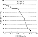
When the cycle characteristics of the secondary cell of measuring embodiment 1-1 to 1-14 and Comparative Examples 1-1 to 1-3, obtain table 1 and result shown in Figure 11.
In order to measure cycle characteristics, carry out cyclic test through the following steps, to measure the discharge capacitance of each secondary cell.At first,, under 23 ℃ of environment, secondary cell is carried out a charge and discharge cycles, afterwards, secondary cell is discharged and recharged once more, to measure the discharge capacity of the 2nd circulation in order to stablize the battery status of secondary cell.Next, under identical environment, secondary cell is carried out 99 charge and discharge cycles, to be determined at the discharge capacity of the 101st circulation.At last, by calculating definite discharge capacitance (%)=(discharge capacity of the discharge capacity of the 101st circulation/the 2nd circulation) * 100.Charge condition is as follows: at secondary cell with 3mA/cm
2Constant current density charging, after cell voltage reaches 4.2V,, reach 0.3mA/cm until current density with the constant-potential charge of this secondary cell with 4.2V
2And as discharging condition, secondary cell is with 3mA/cm
2Constant current density discharge, reach 2.5V until cell voltage.
In addition, adopt, measure the cycle characteristics of the secondary cell of the following examples and Comparative Examples by step and condition same as described above.
[table 1]
Negative electrode active material: silicon (electron beam evaporation)
10 mean roughness Rz=3.5 μ m
Oxygen content=3at% in the negative electrode active material

As shown in table 1 and Figure 11, when forming Si oxide as oxidiferous film by liquid phase deposition, the group's of the fine pore of per unit weight silicon volume is more little, and discharge capacitance is just high more.This result shows that when oxidiferous film invaded in the hole, the surface area of negative electrode active material reduced, so electrolyte is resisted decomposition during discharging and recharging.In this case, be 0.2cm at described volume
3Among/g or the littler embodiment 1-1 to 1-14, the Comparative Examples 1-1 to 1-3 in described scope is high a lot of than this volume for discharge capacitance.Particularly, when volume be 0.05cm
3/ g or more hour, discharge capacitance is higher, when volume is 0cm
3During/g, the discharge capacitance maximum.Therefore, can confirm, in secondary cell according to embodiments of the present invention, at oxidiferous film under the situation that the negative electrode active material that comprises silicon forms, when the group's of the fine pore of per unit weight silicon volume is 0.2cm
3/ g or more hour, cycle characteristics is improved.In this case, identifiablely be, when volume is 0.05cm
3/ g or littler perhaps is 0cm more specifically
3During/g, can obtain better effect.
(embodiment 2-1 to 2-9)
Form secondary cell by the step identical with embodiment 1-1,1-2,1-4,1-7 and 1-10 to 1-14, different is, when negative electrode collector 54A moved forward and backward with respect to evaporation source, siliceous deposits 6 times was carrying out lamination, thereby negative electrode active material has 6 layers structure.At this moment, deposition velocity is 100nm/s.
(Comparative Examples 2)
Form secondary cell by the step identical with Comparative Examples 1-3, different is that as among the embodiment 2-1 to 2-9, negative electrode active material has 6 layers structure.
When the cycle characteristics of the secondary cell of measuring embodiment 2-1 to 2-9 and Comparative Examples 2, obtain the result shown in table 2 and Figure 12.
[table 2]
Negative electrode active material: silicon (electron beam evaporation)
10 mean roughness Rz=3.5 μ m
Oxygen content=3at% in the negative electrode active material

As shown in table 2 and Figure 12, have among the embodiment 2-1 to 2-9 of 6 layers of structure at negative electrode active material, obtain having identical result among the embodiment 1-1 to 1-14 of monolayer constructions will with negative electrode active material.More specifically, the volume the group of the fine pore of per unit weight silicon is 0.2cm
3Among/g or the littler embodiment 2-1 to 2-9, discharge capacitance far above volume not in the Comparative Examples 2 of described scope, and when volume be 0.05cm
3/ g or littler perhaps is 0cm more specifically
3During/g, discharge capacitance is higher.Therefore, can confirm that in secondary cell according to embodiments of the present invention, even the number of plies of negative electrode active material changes, cycle characteristics also is improved.
(embodiment 3-1 to 3-6)
Form secondary cell by the step identical with embodiment 2-1,2-2,2-4,2-5,2-7 and 2-9, different is do not use the solution of the fluoro complex of silicon, and the solution of the fluoro complex of use germanium not to form Si oxide, and form germanium oxide (GeO
2) as oxidiferous film.
(Comparative Examples 3)
Form secondary cell by the step identical with Comparative Examples 2, different is that as among the embodiment 3-1 to 3-6, formation germanium oxide is as oxidiferous film.
(embodiment 4-1 to 4-6)
Form secondary cell by the step identical with embodiment 2-1,2-2,2-4,2-5,2-7 and 2-9, different is do not use the solution of the fluoro complex of silicon, and the solution of the fluoro complex of use tin not to form Si oxide, and form tin-oxide (SnO
2) as oxidiferous film.
(Comparative Examples 4)
Form secondary cell by the step identical with Comparative Examples 2, different is that as among the embodiment 4-1 to 4-6, the formation tin-oxide is as oxidiferous film.
When the cycle characteristics of the secondary cell of measuring embodiment 3-1 to 3-6 and 4-1 to 5-6 and Comparative Examples 3 and 4, obtain the result shown in table 3 and the table 4.
[table 3]
Negative electrode active material: silicon (electron beam evaporation)
10 mean roughness Rz=3.5 μ m
Oxygen content=3at% in the negative electrode active material

[table 4]
Negative electrode active material: silicon (electron beam evaporation)
10 mean roughness Rz=3.5 μ m
Oxygen content=3at% in the negative electrode active material
As shown in table 3 and table 4, forming among germanium oxide or the embodiment 3-1 to 3-6 and 4-1 to 4-6 of tin-oxide by liquid phase deposition as oxidiferous film, obtain with embodiment 1-1 to 1-14 in identical result.More specifically, the volume the group of the fine pore of per unit weight silicon is 0.2cm
3Among/g or the littler embodiment 3-1 to 3-6 and 4-1 to 4-6, discharge capacitance much larger than volume not in the Comparative Examples 3 and 4 of described scope, and when volume be 0.05cm
3/ g or littler perhaps is 0cm more specifically
3During/g, discharge capacitance is higher.In this case, there is the higher trend of discharge capacitance when forming Si oxide.Therefore, can confirm, in secondary cell according to embodiments of the present invention,, also can improve cycle characteristics, and when using Si oxide, can obtain better effect even change the kind of oxidiferous film.
(embodiment 5-1 to 5-3)
Form secondary cell by the step identical with embodiment 2-5, different is, do not use liquid phase deposition, and use sol-gel process (embodiment 5-1), rubbing method (embodiment 5-2) or dip coating (embodiment 5-3), as the method that forms oxidiferous film.
When measuring the secondary cell of embodiment 5-1 to 5-3, obtain the result shown in the table 5.At table 5, provided the result of embodiment 2-5 and Comparative Examples 2 equally.
[table 5]
Negative electrode active material: silicon (electron beam evaporation)
10 mean roughness Rz=3.5 μ m
Oxygen content=3at% in the negative electrode active material

As shown in table 5, in the embodiment 5-1 to 5-3 that oxidiferous film forms by sol-gel process etc., as among the embodiment 2-5 that oxidiferous film forms by liquid phase deposition, discharge capacitance is far above Comparative Examples 2.In this case, there is the higher trend of discharge capacitance when using liquid phase deposition.Therefore, can confirm that in secondary cell according to embodiments of the present invention, even change the method that forms oxidiferous film, cycle characteristics also is improved, and when the employing liquid phase deposition, can obtain better effect.
(embodiment 6-1)
Form secondary cell by the step identical with embodiment 2-1 to 2-9, different is after forming negative electrode active material, not form oxidiferous film, but form the metal material that does not form alloy with lithium.Under the situation that forms metal material, when coating bath provides air, cobalt is deposited on the both sides of negative electrode collector 54A by electrolytic plating method.At this moment, the cobalt electroplating solution that adopts Japan Pure Chemical Co., Ltd is as electroplate liquid, and current density is 2A/dm
2To 5A/dm
2, and electroplating velocity is 10nm/s.And, regulate electroplating time, making group's the volume of the fine pore of per unit weight silicon is 0.2cm
3/ g.
(embodiment 6-2 to 6-6)
Form secondary cell by the step identical with embodiment 6-1, different is that the group's of the fine pore of per unit weight silicon volume is not 0.2cm
3/ g, but be 0.1cm
3/ g (embodiment 6-2), 0.05cm
3/ g (embodiment 6-3), 0.02cm
3/ g (embodiment 6-4), 0.005cm
3/ g (embodiment 6-5) or 0cm
3/ g (embodiment 6-6).
(Comparative Examples 6)
Form secondary cell by the step identical with Comparative Examples 2, different is as embodiment 6-1, to form metal material.
When the cycle characteristics of the secondary cell of measuring embodiment 6-1 to 6-6 and Comparative Examples 6, obtain the result shown in the table 6.
[table 6]
Negative electrode active material: silicon (electron beam evaporation)
10 mean roughness Rz=3.5 μ m
Oxygen content=3at% in the negative electrode active material
As shown in table 6, when forming cobalt as metal material, obtain and the identical result of embodiment 2-1 to 2-9 who forms oxidiferous film by electrolytic plating method.More specifically, the volume the group of the fine pore of per unit weight silicon is 0.2cm
3Among/g or the littler embodiment 6-1 to 6-6, discharge capacitance far above volume not in the Comparative Examples 6 of described scope, and when volume be 0.05cm
3/ g or littler perhaps is 0cm more specifically
3During/g, discharge capacitance is higher.Therefore, can confirm, in secondary cell according to embodiments of the present invention, at metal material under the situation that the negative electrode active material that comprises silicon forms, when the group's of the fine pore of per unit weight silicon volume is 0.2cm
3/ g or more hour, cycle characteristics is improved, and when volume be 0.05cm
3/ g or littler perhaps is 0cm more specifically
3/ g can obtain better effect.
(embodiment 7-1 to 7-6)
Form secondary cell by the step identical with embodiment 6-1 to 6-6, whether different is or not by electrolytic plating method, but form metal material by electroless plating method.At this moment, as plating bath, use the electroless cobalt plating liquid of JapanPure Chemical Co., Ltd, and the plating time is 60 minutes.
(Comparative Examples 7)
Form secondary cell by the step identical with Comparative Examples 2, different is, as among the embodiment 7-1 to 7-6, by electroless plating method formation metal material.
When the cycle characteristics of the secondary cell of measuring embodiment 7-1 to 7-6 and Comparative Examples 7, obtain the result shown in the table 7.
[table 7]
Negative electrode active material: silicon (electron beam evaporation)
10 mean roughness Rz=3.5 μ m
Oxygen content=3at% in the negative electrode active material

As shown in table 7, forming by electroless plating method among the embodiment 7-1 to 7-6 of metal material, obtain and the identical effect of embodiment 6-1 to 6-6 that forms metal material by electrolytic plating method.More specifically, the volume the group of the fine pore of per unit weight silicon is 0.2cm
3Among/g or the littler embodiment 7-1 to 7-6, discharge capacitance far above volume not in the Comparative Examples 7 of described scope, and when volume be 0.05cm
3/ g or littler perhaps is 0cm more specifically
3During/g, discharge capacitance is higher.Therefore, can confirm, in secondary cell according to embodiments of the present invention,, also can improve cycle characteristics even change the method that forms metal material.
(embodiment 8-1 to 8-4)
Form secondary cell by the step identical with embodiment 6-4, different is, raw material as forming metal material does not use cobalt electroplating solution, and uses nickel plating solution (embodiment 8-1), ferroelectric plating bath (embodiment 8-2), zinc electroplate liquid (embodiment 8-3) or copper electroplating liquid (embodiment 8-4).At this moment, under the situation of using nickel plating solution, current density is 2A/dm
2To 10A/dm
2Under the situation of using ferroelectric plating bath, current density is 2A/dm
2To 5A/dm
2Under the situation of using the zinc electroplate liquid, current density is 1A/dm
2To 3A/dm
2And under the situation of using copper electroplating liquid, current density is 2A/dm
2To 8A/dm
2Above-mentioned electroplate liquid is the electroplate liquid of Japan Pure Chemical Co., Ltd.
When the cycle characteristics of the secondary cell of measuring embodiment 8-1 to 8-4, obtain the result shown in the table 8.In table 8, also show the result of embodiment 6-4 and Comparative Examples 6.
[table 8]
Negative electrode active material: silicon (electron beam evaporation)
10 mean roughness Rz=3.5 μ m
Oxygen content=3at% in the negative electrode active material

As shown in table 8, in the embodiment 8-1 to 8-4 of metal materials such as formation nickel, obtain and the suitable discharge capacitance of embodiment 6-4 that wherein forms cobalt, this discharge capacitance is far above Comparative Examples 6.In this case, there is the higher trend of discharge capacitance when using cobalt as metal material.Therefore, can confirm, in secondary cell according to embodiments of the present invention,, also can improve cycle characteristics, and, can obtain better effect when use cobalt during as metal material even change the kind of metal material.
(embodiment 9-1 to 9-6)
Form secondary cell by the step identical with embodiment 2-5, different is, oxygen content in the negative electrode active material is not 3at%, but is 2at% (embodiment 9-1), 10at% (embodiment 9-2), 20at% (embodiment 9-3), 30at% (embodiment 9-4), 40at% (embodiment 9-5) or 45at% (embodiment 9-6).
When the cycle characteristics of the secondary cell of measuring embodiment 9-1 to 9-6, obtain the result shown in table 9 and Figure 13.In table 9, also show the result of embodiment 2-5 and Comparative Examples 2.
[table 9]
Negative electrode active material: silicon (electron beam evaporation)
10 mean roughness Rz=3.5 μ m

As shown in table 9, among the different embodiment 9-1 to 9-6 of the oxygen content in negative electrode active material, as embodiment 2-5, discharge capacitance is far above Comparative Examples 2.In this case, as shown in table 9 and Figure 13, have such trend, promptly along with the increase of oxygen content, discharge capacitance increases, and reduce then, and at content during less than 3at%, discharge capacitance reduces widely.Yet,, can obtain enough discharge capacitances, but battery capacity reduces but when content during greater than 40at%.Therefore, can confirm, in secondary cell according to embodiments of the present invention, even under the situation of the oxygen content in changing negative electrode active material, also can improve cycle characteristics, and when oxygen content be 3~40at% and when comprising two end points, can obtain better effect.
(embodiment 10-1 to 10-3)
Form secondary cell by the step identical with embodiment 2-5, different is, in depositing silicon, in chamber, introduce oxygen etc. off and on, form negative electrode active material thus, making wins contains oxygen district and oxygen content and is higher than first and contains second of oxygen district to contain the oxygen district alternately laminated, rather than introduces oxygen etc. in depositing silicon continuously in chamber, so that comprise oxygen in the negative electrode active material.At this moment, second oxygen content that contains the oxygen district is 3at%, and second number that contains the oxygen district is 2 (embodiment 10-1), 4 (embodiment 10-2) or 6 (embodiment 10-3).
When the cycle characteristics of the secondary cell of measuring embodiment 10-1 to 10-3, obtain the result shown in the table 10.In table 10, also show the result of embodiment 2-5 and Comparative Examples 2.
[table 10]
Negative electrode active material: silicon (electron beam evaporation)
10 mean roughness Rz=3.5 μ m

As shown in table 10, comprise that at negative electrode active material first and second contain among the embodiment 10-1 to 10-3 in oxygen district, as among the embodiment 2-5, discharge capacitance is far above Comparative Examples 2.In this case, the number that existence second contains the oxygen district is big more, the trend that discharge capacitance is high more.Therefore, can confirm, in secondary cell according to embodiments of the present invention, even forming anode active material particles so that comprise that first and second contain under the situation in oxygen district, also cycle characteristics can be improved, and when second number that contains the oxygen district increases, better effect can be obtained.
(embodiment 11-1 to 11-6)
Form secondary cell by the step identical with embodiment 2-5, different is, use purity be 99% silicon and purity be 99.9% metallic element as evaporation source, form the negative electrode active material that comprises silicon and metallic element.At this moment, as metallic element, use iron (embodiment 11-1), nickel (embodiment 11-2), molybdenum (embodiment 11-3), titanium (embodiment 11-4), chromium (embodiment 11-5) or cobalt (embodiment 11-6).At this moment, regulate the evaporation capacity of metallic element, make that the content of metallic element in negative electrode active material is 5at%.
When the cycle characteristics of the secondary cell of measuring embodiment 11-1 to 11-6, obtain the result shown in the table 11.In table 11, also show the result of embodiment 2-5 and Comparative Examples 2.
[table 11]
Negative electrode active material: silicon (electron beam evaporation)
10 mean roughness Rz=3.5 μ m
Oxygen content=3at% in the negative electrode active material
Content=the 5at% of metallic element in the negative electrode active material

As shown in table 11, comprise among the embodiment 11-1 to 11-6 of silicon and metallic element at negative electrode active material, the same with the situation of embodiment 2-5, discharge capacitance is far above Comparative Examples 2.In this case, exist discharge capacitance to be higher than the trend of embodiment 2-5.Therefore, can confirm, in secondary cell according to embodiments of the present invention, even comprise at negative electrode active material under the situation of metallic element, also can improve cycle characteristics, and when comprising metallic element, can obtain better effect.
(embodiment 12-1)
Form secondary cell by the step identical with embodiment 2-5, whether different is or not by electron-beam vapor deposition method, but form negative electrode active material by the RF magnetron sputtering method.At this moment, adopt purity be 99.99% silicon as target, and deposition velocity is 0.5nm/s.
(embodiment 12-2)
Form secondary cell by the step identical with embodiment 2-5, whether different is or not by electron-beam vapor deposition method, but form negative electrode active material by the CVD method.At this moment, use silane and argon gas respectively, and deposition velocity and base reservoir temperature are respectively 1.5nm/s and 200 ℃ as raw material and excited gas.
When measuring the cycle characteristics of embodiment 12-1 and 12-2 secondary cell, obtain the result shown in the table 12.In table 12, also show the result of embodiment 2-5 and Comparative Examples 2.
[table 12]
Negative electrode active material: silicon
10 mean roughness Rz=3.5 μ m
Oxygen content=3at% in the negative electrode active material

As shown in Table 12, in the method that forms negative electrode active material different embodiment 12-1 and 12-2, as among the embodiment 2-5, discharge capacitance is far above Comparative Examples 2.In this case, there is the order gradually high trend of discharge capacitance by CVD method, sputtering method and the electron-beam vapor deposition method of the method for conduct formation negative electrode active material.Therefore, can confirm, in secondary cell according to embodiments of the present invention,, also can improve cycle characteristics, and when the employing evaporation, can obtain better effect even change the method that forms negative electrode active material.
(embodiment 13-1 to 13-7)
Form secondary cell by the step identical with embodiment 2-5, different is, 10 mean roughness Rz on negative electrode collector 54A surface are not 3.5 μ m, but are 1 μ m (embodiment 13-1), 1.5 μ m (embodiment 13-2), 2.5 μ m (embodiment 13-3), 4.5 μ m (embodiment 13-4), 5.5 μ m (embodiment 13-5), 6.5 μ m (embodiment 13-6) or 7 μ m (embodiment 13-7).
When the cycle characteristics of the secondary cell of measuring embodiment 13-1 to 13-7, obtain table 13 and result shown in Figure 14.In table 13, also show the result of embodiment 2-5 and Comparative Examples 2.
[table 13]
Negative electrode active material: silicon (electron beam evaporation)
Oxygen content=3at% in the negative electrode active material

As shown in table 13, in the different embodiment 13-1 to 13-7 of 10 mean roughness Rz, as among the embodiment 2-5, discharge capacitance is far above Comparative Examples 2.In this case, as shown in table 13 and Figure 14, there is increase along with 10 mean roughness Rz, discharge capacitance increases, reduce then, and in 10 mean roughness Rz trend that discharge capacitance reduces greatly during less than 1.5 μ m or greater than 6.5 μ m.Therefore, can confirm, in secondary cell according to embodiments of the present invention, even under the situation of 10 the mean roughness Rz in surface that change negative electrode collector 54A, also can improve cycle characteristics, and when 10 mean roughness Rz be 1.5~6.5 μ m and when comprising two end points, can obtain better effect.
(embodiment 14-1)
Form secondary cell by the step identical with embodiment 2-5, different is, does not adopt EC, but adopts 4-fluoro-1, and 3-dioxolanes-2-ketone (FEC) is as solvent, and it is fluorocarbons acid esters (single fluorine ethylene carbonate ester).
(embodiment 14-2)
Form secondary cell by the step identical with embodiment 2-5, different is, as solvent, add 4,5-two fluoro-1,3-dioxolanes-2-ketone (DFEC) is as fluorocarbons acid esters (difluoro ethylidene carbonic ester), and solvent mixture to have weight ratio be 25: 5: 70 composition (EC: DFEC: DEC).
(embodiment 14-3,14-4)
Form secondary cell by the step identical with embodiment 14-1, different is, in electrolyte, add carbonic acid ethenylidene ester (VC: embodiment 14-3) or vinyl ethylene carbonate ester (VEC: embodiment 14-4) as solvent, they are the cyclic carbonates that contain unsaturated bond.At this moment, VC or the VEC content in electrolyte is 10wt%.
(embodiment 14-5)
Form secondary cell by the step identical with embodiment 14-1, different is, adds as 1 of sultone in electrolyte, and 3-propylidene sultone (PRS) is as solvent.At this moment, the concentration of PRS in electrolyte is 1wt%.
(embodiment 14-6)
Form secondary cell by the step identical with embodiment 14-1, different is to add LiBF4 (LiBF in electrolyte
4) as electrolytic salt.At this moment, LiBF
4Concentration in electrolyte is 0.1mol/kg.
When the cycle characteristics of the secondary cell of measuring embodiment 14-1 to 14-6, obtain the result shown in the table 14.In table 14, also show the result of embodiment 2-5 and Comparative Examples 2.
At this moment, except that cycle characteristics, also measure the expansion characteristics of the secondary cell of embodiment 2-5 and 14-5.In order to measure expansion characteristics, secondary cell is charged through the following steps to measure expansion characteristics.At first,, under 23 ℃ environment, carry out a charge and discharge cycles, and before second charging cycle, measure the thickness of secondary cell in order to stablize the battery status of each secondary cell.Next, after secondary cell charges, measure second charging cycle thickness of secondary cell afterwards under equivalent environment.At last, by calculating definite expansion rate (%)=[thickness before (thickness before the thickness-charging after the charging)/charging] * 100.At this moment, charge condition identical when measuring cycle characteristics.
[table 14]
Negative electrode active material: silicon (electron beam evaporation)
10 mean roughness Rz=3.5 μ m
Oxygen content=3at% in the negative electrode active material

As shown in table 14, in the diverse embodiment 14-1 to 14-6 of the composition of solvent and electrolytic salt, as the situation of embodiment 2-5, discharge capacitance is far above Comparative Examples 2.Therefore, can confirm that in secondary cell according to embodiments of the present invention, even change the composition of solvent or the kind of electrolytic salt, cycle characteristics also can be improved.
Particularly, in embodiment 14-1 and 14-2, discharge capacitance is higher than embodiment 2-5.Trend when the discharge capacitance when in this case, existing solvent to comprise DFEC is higher than solvent and comprises FEC.Therefore, can confirm, when solvent comprises the fluorocarbons acid esters, can improve cycle characteristics, and when using difluoro ethylidene carbonic ester, can obtain better effect when using single fluorine ethylidene carbonic ester as the fluorocarbons acid esters.
And in embodiment 14-3 to 14-6, discharge capacitance is higher than embodiment 2-5.Discharge capacitance when in this case, existing solvent to comprise VC or VEC is higher than solvent and comprises PRS or LiBF
4The time trend.Therefore, can confirm, when comprising cyclic carbonate, the sultone that contains unsaturated bond or contain boron and during the electrolytic salt of fluorine, can further improve cycle characteristics, and, can obtain better effect when using when containing the cyclic carbonate of unsaturated bond.
Comprise among the embodiment 14-5 of PRS that at solvent do not comprise that with solvent the embodiment 2-5 of PRS compares, expansion rate reduces widely.Therefore, can confirm, in secondary cell according to embodiments of the present invention, when solvent comprises sultone etc., can improve expansion characteristics.
(embodiment 15-1)
Form secondary cell by the step identical with embodiment 2-5, whether different is or not to form stacked film type secondary cell, but form the prismatic secondary cell shown in Fig. 5 and 6 through the following steps.
At first, after forming positive pole 21 and negative pole 22, respectively the positive wire 24 of aluminum and the negative wire 25 of nickel system are connected to positive electrode collector 21A and negative electrode collector 22A by welding.Then, by this sequential cascade, longitudinally screw winding is molded as flat then, forms battery unit 20 thus with positive pole 21, dividing plate 23 and negative pole 22.Then, after the battery case 11 of aluminum that battery unit 20 is packed into, insulation board 12 is arranged on the battery unit 20.Next, positive wire 24 and negative wire 25 are welded on respectively on anodal pin one 5 and the battery case 11, afterwards, battery cover 13 are fixed on the openend of battery case 11 by laser welding.At last, in battery case 11, inject electrolyte, and fill hand-hole 19, form prismatic battery thus with seal 19A by hand-hole 19.
(embodiment 15-2)
Form secondary cell by the step identical with embodiment 15-1, different is not use the battery case 11 of aluminum, and use battery case 11 made of iron.
When the cycle characteristics of the secondary cell of measuring embodiment 15-1 and 15-2, obtain the result shown in the table 15.In table 15, also show the result of embodiment 2-5 and Comparative Examples 2.
[table 15]
Negative electrode active material: silicon (electron beam evaporation)
10 mean roughness Rz=3.5 μ m
Oxygen content=3at% in the negative electrode active material

As shown in table 15, in battery structure different embodiment 15-1 and 15-2, as the situation of embodiment 2-5, discharge capacitance is far above Comparative Examples 2.In this case, discharge capacitance is higher than embodiment 2-5, and the discharge capacitance when exist using battery case 11 made of iron is higher than the trend of the battery case 11 of aluminum.Therefore, can confirm, in secondary cell according to embodiments of the present invention, even the change battery structure also can improve cycle characteristics, and when battery structure is prismatic type, with battery structure is that the situation of stacked film type is compared, cycle characteristics is further improved, and when using battery case 11 made of iron, can obtain better effect.Although do not describe with reference to concrete example, but at package is in the prismatic secondary cell of being made by metal material, cycle characteristics and expansion characteristics all are further improved than stacked film type secondary cell, so, it is evident that, at package is in the column secondary battery of being made by metal material, can obtain identical effect.
(embodiment 16-1 to 16-4)
Form secondary cell by the step identical with embodiment 2-1 to 2-9, different is, changes the move forward and backward speed of negative electrode collector 54A with respect to evaporation source, and making the group's of per unit weight silicon very small pores volume is 0.2cm
3/ g (embodiment 16-1), 0.05cm
3/ g (embodiment 16-2), 0.01cm
3/ g (embodiment 16-3) or 0cm
3/ g (embodiment 16-4).The group's of per unit weight silicon very small pores volume is by following numerical evaluation: be formed with the weight that deducts negative electrode collector 54A in the total weight of negative electrode collector 54A of negative electrode active material from it and definite numerical value (weight of negative electrode active material silicon); And invading the numerical value that diameter is the amount of mercury in 3~20nm and the hole that comprises two end points (very small pores group volume), it is that mercury porosimeter (AutoPore 9500 series) by Micromeritics is measured.
(Comparative Examples 16)
Form secondary cell by the step identical with Comparative Examples 2, different is that the group's of per unit weight silicon very small pores volume is 0.3cm
3/ g.
When the cycle characteristics of the secondary cell of measuring embodiment 16-1 to 16-4 and Comparative Examples 16, obtain the result shown in the table 16.
[table 16]
Negative electrode active material: silicon (electron beam evaporation)
10 mean roughness Rz=3.5 μ m
Oxygen content=3at% in the negative electrode active material

As shown in table 16, forming under the situation of oxidiferous film, be 0.2cm at the group's of per unit weight silicon very small pores volume
3Among/g or the littler embodiment 16-1 to 16-4, discharge capacitance far above volume not in the Comparative Examples 16 of this scope, and when volume be 0.05cm
3/ g or littler perhaps is 0cm
3During/g, discharge capacitance is higher.In this case, consider the difference between the group (group and the group of very small pores of fine pore) of hole, exist relate to very small pores group the discharge capacitance of embodiment 16-1 to 16-4 be higher than relate to the fine pore group the trend of embodiment 2-1,2-4,2-6 and 2-9.The result shows that in order to reduce the surface area of negative electrode active material, the group's of very small pores volume has the bigger influence of volume than the group of fine pore.Therefore, can confirm, in secondary cell according to embodiments of the present invention, under the situation that forms oxidiferous film, when the group's of per unit weight silicon very small pores volume is 0.2cm
3/ g or more hour can further improve cycle characteristics.In this case, can confirm, when volume is 0.05cm
3/ g or littler perhaps is 0cm more specifically
3During/g, can obtain better effect.
(embodiment 17-1 to 17-4)
Form secondary cell by the step identical with embodiment 6-1 to 6-6, different is, changes the move forward and backward speed of negative electrode collector 54A with respect to evaporation source, makes that group's the volume of per unit weight silicon very small pores is 0.2cm
3/ g (embodiment 17-1), 0.05cm
3/ g (embodiment 17-2), 0.01cm
3/ g (embodiment 17-3) or 0cm
3/ g (embodiment 17-4).
(Comparative Examples 17)
Form secondary cell by the step identical with Comparative Examples 6, different is that the group's of per unit weight silicon very small pores volume is 0.3cm
3/ g.
When the cycle characteristics of the secondary cell of measuring embodiment 17-1 to 17-4 and Comparative Examples 17, obtain the result shown in the table 17.
[table 17]
Negative electrode active material: silicon (electron beam evaporation)
10 mean roughness Rz=3.5 μ m
Oxygen content=3at% in the negative electrode active material

As shown in Table 17, forming under the situation of metal material, be 0.2cm at the group's of per unit weight silicon very small pores volume
3Among/g or the littler embodiment 17-1 to 17-4, discharge capacitance exceeds the Comparative Examples 17 of this scope far above volume, and when volume be 0.05cm
3/ g or littler perhaps is 0cm
3During/g, discharge capacitance is higher.In this case, the same with result shown in the table 16, exist the group's who comprises very small pores embodiment 17-1,17-3 and the discharge capacitance of 17-4 to be higher than the group's who comprises the fine pore embodiment 6-1,6-3 and the trend of 6-6.Therefore, can confirm, in secondary cell according to embodiments of the present invention, even under the situation that forms metal material, when the group's of per unit weight silicon very small pores volume is 0.2cm
3During/g, also can further improve cycle characteristics.In this case, can confirm, when volume is 0.05cm
3/ g or littler perhaps is 0cm more specifically
3During/g, can obtain better effect.
From table 1 to 17 and Figure 11 to 14 can clearly be seen that, comprise at negative electrode active material under group's's (diameter be 3~50nm and the hole that comprises two end points group) the situation of silicon and fine pore, when the group's of the fine pore of per unit weight silicon volume is 0.2cm
3/ g or more hour, no matter the composition of the number of plies of other condition such as negative electrode active material or negative electrode active material how, cycle characteristics can be improved.
Although with reference to embodiment and embodiment the present invention has been described, the present invention is not limited to described embodiment and embodiment, and is to revise by different way.For example, in above-mentioned embodiment and the foregoing description, for the group's of the fine pore that makes per unit weight silicon volume is 0.2cm
3/ g or littler scope can comprise oxidiferous film or metal material in the hole where necessary; Yet the present invention is not limited to this.As long as the group's of the fine pore of per unit weight silicon volume is 0.2cm
3/ g or littler can comprise any other packing material in the hole.Preferred packing material does not have special influence to the performance of secondary cell.
In above-mentioned embodiment and above-mentioned material, as the kind of secondary cell, capacity of negative plates has wherein been described by the embedding of lithium with deviate from the lithium rechargeable battery of expression; Yet the present invention is not limited to lithium rechargeable battery.Secondary cell of the present invention is equally applicable to embed and to deviate from the charging capacity of negative material of lithium less than the secondary cell of the charging capacity of positive pole, thereby the capacity of negative pole comprises based on the embedding of lithium and the capacity of deviating from and based on the capacity of separating out and dissolving of lithium, and represents with sum of the two.
In above-mentioned embodiment and the foregoing description, described the situation that battery has prismatic type, cylindrical shape type or stacked film type, and battery unit has the situation of screw winding structure; Yet secondary cell of the present invention is equally applicable to secondary cell and has any other shape such as monetary apparatus or button-shaped situation, but also is applicable to that battery unit has the situation of any other structure as the sandwich structure.
In above-mentioned embodiment and the foregoing description, described with the situation of lithium as the electrode reaction thing; Yet, can use any other I family element such as sodium (Na) or potassium (K) in the long formula periodic table of elements, II family element such as magnesium (Mg) or calcium (Ca), perhaps any other light metal such as aluminium.The long formula periodic table of elements is the revised edition of the IUPAC inorganic chemistry nomenclature of IUPAC (international pure and applied chemistry federation) issue.Also in this case, as negative electrode active material, can use the negative material described in the above-mentioned embodiment.
In above-mentioned embodiment and the foregoing description, group's the optimum range of volume of the fine pore of per unit weight silicon in negative pole of the present invention or the secondary cell has been described, this optimum range comes from the result of embodiment; Yet group's the volume that the fine pore of per unit weight silicon is not got rid of in this description exceeds the possibility of above-mentioned scope.More specifically, above-mentioned optimum range is to realize the particularly preferred scope of effect of the present invention, as long as and can realize effect of the present invention, described volume can depart from above-mentioned scope to a certain extent.To above-mentioned volume without limits, this is applicable to the group's of per unit weight silicon very small pores volume, the oxygen content in the negative electrode active material, 10 the mean roughness Rz in surface of negative electrode collector etc. too.
It will be understood by those of skill in the art that in the scope of claims and equivalent thereof, can various modifications, combination, inferior combination and variant occur according to designing requirement and other factor.
Claims (48)
1. negative pole comprises:
Negative electrode collector; And
Be arranged in the negative electrode active material layer on the negative electrode collector,
Wherein this negative electrode active material layer comprises negative electrode active material, and this negative electrode active material contains silicon (Si), and to comprise diameter be 3~50nm and the group who comprises the hole of two end points, and
By the silicon of per unit weight, this diameter is that the group's of 3~50nm and the hole that comprises two end points volume is 0.2cm
3/ g or littler, this volume utilize the mercury porosimeter to measure by mercury porosimetry.
2. according to the negative pole of claim 1, wherein
By the silicon of per unit weight, this diameter is that the group's of 3~50nm and the hole that comprises two end points volume is 0.05cm
3/ g or littler.
3. according to the negative pole of claim 1, wherein
By the silicon of per unit weight, this diameter is that the group's of 3~50nm and the hole that comprises two end points volume is 0cm
3/ g.
4. according to the negative pole of claim 1, wherein
By the silicon of per unit weight, diameter is that the group's of 3~20nm and the hole that comprises two end points volume is 0.2cm
3/ g or littler, this volume utilize the mercury porosimeter to measure by mercury porosimetry.
5. according to the negative pole of claim 4, wherein
By the silicon of per unit weight, this diameter is that the group's of 3~20nm and the hole that comprises two end points volume is 0.05cm
3/ g or littler.
6. according to the negative pole of claim 4, wherein
By the silicon of per unit weight, this diameter is that the group's of 3~20nm and the hole that comprises two end points volume is 0cm
3/ g.
7. according to the negative pole of claim 1, wherein
Comprise oxidiferous film in the hole of described negative electrode active material layer.
8. according to the negative pole of claim 7, wherein
Described oxidiferous film comprises at least a following oxide that is selected from: the oxide of the oxide of silicon, germanium (Ge), and the oxide of tin (Sn).
9. according to the negative pole of claim 7, wherein
Described oxidiferous film forms by liquid phase deposition, sol-gel process, rubbing method or dip coating.
10. according to the negative pole of claim 1, wherein
Described negative electrode active material layer comprise not with hole in the electrode reaction thing form the metal material of alloy.
11. according to the negative pole of claim 10, wherein
Described metal material comprises and is selected from least a in following: iron (Fe), cobalt (Co), nickel (Ni), zinc (Zn), and copper (Cu).
12. according to the negative pole of claim 10, wherein
Described metal material forms by electrolytic plating method or electroless plating method.
13. according to the negative pole of claim 1, wherein
Described negative electrode active material is the form of a plurality of particles.
14. according to the negative pole of claim 13, wherein
Described negative electrode active material has multi-ply construction in its particle.
15. according to the negative pole of claim 1, wherein
Described negative electrode active material forms by vapor phase method.
16. according to the negative pole of claim 1, wherein
Described negative electrode active material comprises oxygen (O), and the oxygen content in the described negative electrode active material is 3~40at% and comprises two end points.
17. according to the negative pole of claim 1, wherein
Described negative electrode active material comprises at least a following metallic element that is selected from: iron, cobalt, nickel, chromium (Cr), titanium (Ti), and molybdenum (Mo).
18. according to the negative pole of claim 1, wherein
Described negative electrode active material comprises along the oxygen containing oxygen district that contains of its thickness direction bag, and this oxygen content that contains the oxygen district is higher than other the regional oxygen content except that this contains the oxygen district.
19. according to the negative pole of claim 1, wherein
10 the mean roughness Rz in the surface of described negative electrode collector are 1.5~6.5 μ m and comprise two end points.
20. a secondary cell, it comprises positive pole, negative pole and electrolyte, wherein
Described negative pole comprises negative electrode collector and the negative electrode active material layer that is arranged on this negative electrode collector,
This negative electrode active material layer comprises negative electrode active material, and this negative electrode active material contains silicon, and to comprise diameter be 3~50nm and the group who comprises the hole of two end points, and
By the silicon of per unit weight, this diameter is that the group's of 3~50nm and the hole that comprises two end points volume is 0.2cm
3/ g or littler, this volume utilize the mercury porosimeter to measure by mercury porosimetry.
21. according to the secondary cell of claim 20, wherein
By the silicon of per unit weight, this diameter is that the group's of 3~50nm and the hole that comprises two end points volume is 0.05cm
3/ g or littler.
22. according to the secondary cell of claim 20, wherein
By the silicon of per unit weight, this diameter is that the group's of 3~50nm and the hole that comprises two end points volume is 0cm
3/ g.
23. according to the secondary cell of claim 20, wherein
By the silicon of per unit weight, diameter is that the group's of 3~20nm and the hole that comprises two end points volume is 0.2cm
3/ g or littler, this volume utilize the mercury porosimeter to measure by mercury porosimetry.
24. according to the secondary cell of claim 23, wherein
By the silicon of per unit weight, this diameter is that the group's of 3~20nm and the hole that comprises two end points volume is 0.05cm
3/ g or littler.
25. according to the secondary cell of claim 23, wherein
By the silicon of per unit weight, this diameter is that the group's of 3~20nm and the hole that comprises two end points volume is 0cm
3/ g.
26. according to the secondary cell of claim 20, wherein
Described negative electrode active material layer comprises oxidiferous film in hole.
27. according to the secondary cell of claim 26, wherein
Described oxidiferous film comprises at least a following oxide that is selected from: the oxide of silicon, the oxide of germanium, and the oxide of tin.
28. according to the secondary cell of claim 26, wherein
Described oxidiferous film forms by liquid phase deposition, sol-gel process, rubbing method or dip coating.
29. according to the secondary cell of claim 20, wherein
Described negative electrode active material layer comprise not with hole in the electrode reaction thing form the metal material of alloy.
30. according to the secondary cell of claim 29, wherein
Described metal material comprises and is selected from least a in following: iron, cobalt, nickel, zinc, and copper.
31. according to the secondary cell of claim 29, wherein
Described metal material forms by electrolytic plating method or electroless plating method.
32. according to the secondary cell of claim 20, wherein
Described negative electrode active material is the form of a plurality of particles.
33. according to the secondary cell of claim 32, wherein
Described negative electrode active material has multi-ply construction in its particle.
34. according to the secondary cell of claim 20, wherein
Described negative electrode active material forms by vapor phase method.
35. according to the secondary cell of claim 20, wherein
Described negative electrode active material contains aerobic, and the oxygen content in the described negative electrode active material is the 3~40at% scope that comprises two end points.
36. according to the secondary cell of claim 20, wherein
Described negative electrode active material comprises at least a following metallic element that is selected from: iron, cobalt, nickel, chromium, titanium, and molybdenum.
37. according to the secondary cell of claim 20, wherein
Described negative electrode active material comprises along the oxygen containing oxygen district that contains of its thickness direction bag, and this oxygen content that contains the oxygen district is higher than other the regional oxygen content except that containing this oxygen district.
38. according to the secondary cell of claim 20, wherein
10 the mean roughness Rz in the surface of described negative electrode collector are 1.5~6.5 μ m and comprise two end points.
39. according to the secondary cell of claim 20, wherein
Described electrolyte comprises the solvent that comprises sultone.
40. according to the secondary cell of claim 39, wherein
Described sultone is 1,3-propylidene sultone.
41. according to the secondary cell of claim 20, wherein
Described electrolyte comprises solvent, and this solvent comprises the cyclic carbonate that contains unsaturated bond.
42. according to the secondary cell of claim 41, wherein
The described cyclic carbonate that contains unsaturated bond is carbonic acid ethenylidene ester or vinyl ethylene carbonate ester.
43. according to the secondary cell of claim 20, wherein
Described electrolyte comprises solvent, and this solvent comprises the fluorocarbons acid esters.
44. according to the secondary cell of claim 43, wherein
Described fluorocarbons acid esters is a difluoro ethylidene carbonic ester.
45. according to the secondary cell of claim 20, wherein
Described electrolyte comprises electrolytic salt, and this electrolytic salt contains boron (B) and fluorine (F).
46. according to the secondary cell of claim 45, wherein
Described electrolytic salt is LiBF4 (LiBF
4).
47. according to the secondary cell of claim 20, wherein
Described positive pole, negative pole and electrolyte are contained in the cylindrical or prismatic package.
48. according to the secondary cell of claim 47, wherein
Described package comprises iron or ferroalloy.
Priority Applications (1)
| Application Number | Priority Date | Filing Date | Title |
|---|---|---|---|
| CN201310611544.7A CN103730627B (en) | 2007-06-05 | 2008-06-05 | Anode and secondary battery |
Applications Claiming Priority (3)
| Application Number | Priority Date | Filing Date | Title |
|---|---|---|---|
| JP2007149253 | 2007-06-05 | ||
| JP149253/07 | 2007-06-05 | ||
| JP015256/08 | 2008-01-25 |
Related Child Applications (1)
| Application Number | Title | Priority Date | Filing Date |
|---|---|---|---|
| CN201310611544.7A Division CN103730627B (en) | 2007-06-05 | 2008-06-05 | Anode and secondary battery |
Publications (1)
| Publication Number | Publication Date |
|---|---|
| CN101320794A true CN101320794A (en) | 2008-12-10 |
Family
ID=40180723
Family Applications (2)
| Application Number | Title | Priority Date | Filing Date |
|---|---|---|---|
| CNA2008101098849A Pending CN101320794A (en) | 2007-06-05 | 2008-06-05 | Anode and secondary battery |
| CN201310611544.7A Active CN103730627B (en) | 2007-06-05 | 2008-06-05 | Anode and secondary battery |
Family Applications After (1)
| Application Number | Title | Priority Date | Filing Date |
|---|---|---|---|
| CN201310611544.7A Active CN103730627B (en) | 2007-06-05 | 2008-06-05 | Anode and secondary battery |
Country Status (3)
| Country | Link |
|---|---|
| JP (1) | JP5245425B2 (en) |
| KR (1) | KR101503528B1 (en) |
| CN (2) | CN101320794A (en) |
Cited By (3)
| Publication number | Priority date | Publication date | Assignee | Title |
|---|---|---|---|---|
| CN104584260A (en) * | 2012-09-26 | 2015-04-29 | 三洋电机株式会社 | Gasket for secondary cell, and secondary cell |
| CN106133955A (en) * | 2014-03-13 | 2016-11-16 | 山阳特殊制钢株式会社 | The negative material of electrical storage device |
| CN106486647A (en) * | 2015-08-31 | 2017-03-08 | 华为技术有限公司 | A kind of composite cathode material for lithium ion cell and preparation method thereof and lithium ion battery |
Families Citing this family (6)
| Publication number | Priority date | Publication date | Assignee | Title |
|---|---|---|---|---|
| KR101558537B1 (en) * | 2008-08-26 | 2015-10-08 | 삼성전자주식회사 | Porous anode active material manufacturing method thereof and anode and lithum battery comprising the same |
| JP5820662B2 (en) * | 2010-09-06 | 2015-11-24 | 株式会社Nttファシリティーズ | Lithium ion secondary battery |
| US9166220B2 (en) | 2012-02-13 | 2015-10-20 | Samsung Sdi Co., Ltd. | Negative active material for rechargeable lithium battery, method of preparing the same and rechargeable lithium battery including the same |
| JP5652679B2 (en) * | 2013-03-28 | 2015-01-14 | ソニー株式会社 | Negative electrode for lithium ion secondary battery and lithium ion secondary battery |
| JP6306608B2 (en) * | 2013-12-03 | 2018-04-04 | エルジー・ケム・リミテッド | Porous silicon-based negative electrode active material, method for producing the same, and lithium secondary battery including the same |
| EP4235937A3 (en) * | 2016-10-13 | 2023-11-08 | Tesla, Inc. | Large-format battery anodes comprising silicon particles |
Family Cites Families (15)
| Publication number | Priority date | Publication date | Assignee | Title |
|---|---|---|---|---|
| JP3717085B2 (en) * | 1994-10-21 | 2005-11-16 | キヤノン株式会社 | Negative electrode for secondary battery, secondary battery having the negative electrode, and method for producing electrode |
| JP3941235B2 (en) * | 1998-05-13 | 2007-07-04 | 宇部興産株式会社 | Non-aqueous secondary battery |
| JP2001210323A (en) * | 2000-01-26 | 2001-08-03 | Matsushita Electric Ind Co Ltd | Nonaqueous electrolyte secondary battery |
| JP4229567B2 (en) * | 2000-03-28 | 2009-02-25 | 三洋電機株式会社 | Secondary battery |
| JP3714665B2 (en) * | 2002-01-25 | 2005-11-09 | Necトーキン栃木株式会社 | Method for producing lithium ion secondary battery |
| JP2004139768A (en) * | 2002-10-16 | 2004-05-13 | Hitachi Maxell Ltd | Porous thin film electrode and lithium secondary battery using this as negative electrode |
| JP4686974B2 (en) * | 2002-12-17 | 2011-05-25 | 三菱化学株式会社 | Anode for non-aqueous electrolyte secondary battery and non-aqueous electrolyte secondary battery using the same |
| JP3827642B2 (en) * | 2003-01-06 | 2006-09-27 | 三星エスディアイ株式会社 | Negative electrode active material for lithium secondary battery, method for producing the same, and lithium secondary battery |
| JP2004319469A (en) | 2003-04-02 | 2004-11-11 | Matsushita Electric Ind Co Ltd | Negative electrode active substance and nonaqueous electrolyte secondary cell |
| JP2004327330A (en) * | 2003-04-25 | 2004-11-18 | Matsushita Electric Ind Co Ltd | Electrode material for nonaqueous electrolyte secondary battery, manufacturing method of same, and nonaqueous electrolyte secondary battery using same |
| JP3764470B1 (en) * | 2004-09-09 | 2006-04-05 | 三井金属鉱業株式会社 | Anode for non-aqueous electrolyte secondary battery |
| US7615314B2 (en) | 2004-12-10 | 2009-11-10 | Canon Kabushiki Kaisha | Electrode structure for lithium secondary battery and secondary battery having such electrode structure |
| JP4213688B2 (en) * | 2005-07-07 | 2009-01-21 | 株式会社東芝 | Nonaqueous electrolyte battery and battery pack |
| JP4622803B2 (en) * | 2005-10-25 | 2011-02-02 | ソニー株式会社 | Negative electrode for lithium ion secondary battery, lithium ion secondary battery, and production method thereof |
| JP4525742B2 (en) * | 2007-01-30 | 2010-08-18 | ソニー株式会社 | Negative electrode for lithium ion secondary battery and lithium ion secondary battery |
-
2008
- 2008-01-25 JP JP2008015256A patent/JP5245425B2/en active Active
- 2008-06-04 KR KR1020080052668A patent/KR101503528B1/en active IP Right Grant
- 2008-06-05 CN CNA2008101098849A patent/CN101320794A/en active Pending
- 2008-06-05 CN CN201310611544.7A patent/CN103730627B/en active Active
Cited By (4)
| Publication number | Priority date | Publication date | Assignee | Title |
|---|---|---|---|---|
| CN104584260A (en) * | 2012-09-26 | 2015-04-29 | 三洋电机株式会社 | Gasket for secondary cell, and secondary cell |
| CN106133955A (en) * | 2014-03-13 | 2016-11-16 | 山阳特殊制钢株式会社 | The negative material of electrical storage device |
| CN106133955B (en) * | 2014-03-13 | 2019-04-26 | 山阳特殊制钢株式会社 | The negative electrode material of electrical storage device |
| CN106486647A (en) * | 2015-08-31 | 2017-03-08 | 华为技术有限公司 | A kind of composite cathode material for lithium ion cell and preparation method thereof and lithium ion battery |
Also Published As
| Publication number | Publication date |
|---|---|
| KR101503528B1 (en) | 2015-03-17 |
| KR20080107287A (en) | 2008-12-10 |
| CN103730627B (en) | 2017-04-12 |
| JP5245425B2 (en) | 2013-07-24 |
| CN103730627A (en) | 2014-04-16 |
| JP2009016339A (en) | 2009-01-22 |
Similar Documents
| Publication | Publication Date | Title |
|---|---|---|
| US10476070B2 (en) | Anode and battery | |
| CN101320795B (en) | Anode and battery | |
| CN101364645B (en) | Current collector, anode, and battery | |
| US20230402612A1 (en) | Materials and methods for components of lithium batteries | |
| JP6765683B2 (en) | Electrode assembly for lithium secondary battery, lithium secondary battery and battery module including this | |
| KR101628638B1 (en) | Anode and secondary battery | |
| US9698416B2 (en) | Anode and secondary battery with anode material with pore group with low volumetric capacity | |
| US8951672B2 (en) | Anode, method of manufacturing it, battery, and method of manufacturing it | |
| KR102609469B1 (en) | Passivation of lithium metal by two-dimensional materials for rechargeable batteries | |
| CN101355147B (en) | Cathode and battery | |
| CN101246953B (en) | Cathode and its manufacture method, battery and its manufacture method | |
| EP2685530B1 (en) | Negative electrode active material for electrical device, and electrical device | |
| CN101320794A (en) | Anode and secondary battery | |
| EP2685531B1 (en) | Negative electrode active material for electrical devices | |
| CN111554918A (en) | Lithium ion secondary battery and method for producing active material | |
| EP2717355B1 (en) | Negative electrode active material for electrical devices | |
| CN111758176A (en) | Method for predoping negative electrode active material, method for producing negative electrode, and method for producing power storage device | |
| EP2800175B1 (en) | Negative electrode active material for electrical device, negative electrode for electrical device, and electrical device | |
| JP6098719B2 (en) | Negative electrode active material for electric device and electric device using the same | |
| EP3780234A1 (en) | Nonaqueous electrolyte secondary battery | |
| KR20170032905A (en) | Carbon nanotube-based lithium ion battery |
Legal Events
| Date | Code | Title | Description |
|---|---|---|---|
| C06 | Publication | ||
| PB01 | Publication | ||
| C10 | Entry into substantive examination | ||
| SE01 | Entry into force of request for substantive examination | ||
| C12 | Rejection of a patent application after its publication | ||
| RJ01 | Rejection of invention patent application after publication |
Application publication date: 20081210 |