CN101297456A - A converter station - Google Patents
A converter station Download PDFInfo
- Publication number
- CN101297456A CN101297456A CNA2006800400008A CN200680040000A CN101297456A CN 101297456 A CN101297456 A CN 101297456A CN A2006800400008 A CNA2006800400008 A CN A2006800400008A CN 200680040000 A CN200680040000 A CN 200680040000A CN 101297456 A CN101297456 A CN 101297456A
- Authority
- CN
- China
- Prior art keywords
- converter
- current conversion
- conversion station
- valve
- series
- Prior art date
- Legal status (The legal status is an assumption and is not a legal conclusion. Google has not performed a legal analysis and makes no representation as to the accuracy of the status listed.)
- Pending
Links
Images

Classifications
-
- H—ELECTRICITY
- H02—GENERATION; CONVERSION OR DISTRIBUTION OF ELECTRIC POWER
- H02J—CIRCUIT ARRANGEMENTS OR SYSTEMS FOR SUPPLYING OR DISTRIBUTING ELECTRIC POWER; SYSTEMS FOR STORING ELECTRIC ENERGY
- H02J3/00—Circuit arrangements for ac mains or ac distribution networks
- H02J3/36—Arrangements for transfer of electric power between ac networks via a high-tension dc link
-
- H—ELECTRICITY
- H02—GENERATION; CONVERSION OR DISTRIBUTION OF ELECTRIC POWER
- H02J—CIRCUIT ARRANGEMENTS OR SYSTEMS FOR SUPPLYING OR DISTRIBUTING ELECTRIC POWER; SYSTEMS FOR STORING ELECTRIC ENERGY
- H02J3/00—Circuit arrangements for ac mains or ac distribution networks
- H02J3/38—Arrangements for parallely feeding a single network by two or more generators, converters or transformers
-
- Y—GENERAL TAGGING OF NEW TECHNOLOGICAL DEVELOPMENTS; GENERAL TAGGING OF CROSS-SECTIONAL TECHNOLOGIES SPANNING OVER SEVERAL SECTIONS OF THE IPC; TECHNICAL SUBJECTS COVERED BY FORMER USPC CROSS-REFERENCE ART COLLECTIONS [XRACs] AND DIGESTS
- Y02—TECHNOLOGIES OR APPLICATIONS FOR MITIGATION OR ADAPTATION AGAINST CLIMATE CHANGE
- Y02E—REDUCTION OF GREENHOUSE GAS [GHG] EMISSIONS, RELATED TO ENERGY GENERATION, TRANSMISSION OR DISTRIBUTION
- Y02E60/00—Enabling technologies; Technologies with a potential or indirect contribution to GHG emissions mitigation
- Y02E60/60—Arrangements for transfer of electric power between AC networks or generators via a high voltage DC link [HVCD]
Landscapes
- Engineering & Computer Science (AREA)
- Power Engineering (AREA)
- Rectifiers (AREA)
- Inverter Devices (AREA)
- Supply And Distribution Of Alternating Current (AREA)
Abstract
A converter station for connecting an AC system to an HVDC transmission line comprises at least two converters arranged in two separate converter valve halls (40, 41). The station comprises a separate control device (49, 50) for the control of each converter and separate means for providing auxiliary power for each converter. A separate means (51, 52) for controlling the overall operation conditions is arranged for each converter making each converter self supporting. The converter valve halls are separated by/a substantial space.
Description
Technical field and prior art
The present invention relates to a kind of current conversion station, be used for the AC system is connected to the HVDC power transmission line, described current conversion station comprises at least two converters, it is arranged in the valve hall separately, and each converter has the DC side that is used to connect described power transmission line and the AC side that is used to be connected described AC system, described current conversion station comprises: the control appliance that is configured to control the operation of described converter, be used to described converter that the device of auxiliary power is provided, and be used to control the overall work situation of described converter as cooling off the device of its parts.
The invention is not restricted to described HVDC (high voltage direct current, High Voltage DirectCurrent) voltage of any specific grade between the utmost point of power transmission line, but the present invention is particularly useful for the above such voltage of 500kV, this means the sizable power of described power line transmission, and the transmission system under the current conversion station needs very high-caliber reliability.The present invention also is not limited to the electric current by any specific grade of the utmost point of described power transmission line, but the rated current of described power transmission line is preferably more than the 1kA.
In Fig. 1, schematically show the master-plan of such HVDC transmission system.Show current conversion station the 1, the 2nd, how to be arranged in each end of HVDC power transmission line 3, this HVDC power transmission line 3 has two utmost points, and one is anodal 4, one is negative pole 5.AC system 6 is connected to each current conversion station by transformer 7, is used to obtain the appropriate level of the voltage of described AC system.The AC system of supposing to be connected to current conversion station 1 is the electricity generation system of the power plant form with generator of any type, and this current conversion station is designed to as rectifier work, hypothesis is connected to the AC system of current conversion station 2 and is connected to consume system or the network of electricity consumer as industry and resident community simultaneously, and supposes that this current conversion station is as inverter work.Each current conversion station has two converters 8,9, the DC side of each in the converter 8,9 is connected respectively to the corresponding utmost point in described two utmost points 4,5 on the one hand, be connected to the shared DC neutral arrangement 10 of converter on the other hand, the low-pressure side of this DC neutral arrangement 10 is connected to ground, is used for limiting on each converter certain voltage.Converter comprises some current valve of for example 12 pulse-bridge configuration of any known configurations.Converter can be line commutated current source converters (line commutated Current Source Converter), wherein switch element as thyristor as described in the zero crossing place of AC electric current of AC system turn-off.Converter can also be forced commutation voltage source converter (forced commutated Voltage SourceConverter), and wherein said switch element is the shutoff device according to the control of pulse-width modulation (PWM) pattern.
The HVDC transmission system is with respect to the advantage of AC transmission system, produce quite low loss in the power transmission line between two current conversion stations, described two current conversion stations are positioned at each end of this power transmission line, however with in the AC transmission system, compare, current conversion station is expensive more usually in the HVDC transmission system.Therefore, to be generally used for transmitting often be the high-power of m. gigawatt (GW) level to the HVDC transmission system.This means, if for example owing to earth fault, the whole or part tripping operation of such transmission system, that is have to be disconnected, then the consequence for the AC system that is connected may be very serious.The tripping operation of such high power transmission can produce damaging influence to electric power networks by power disturbance, and for example consequently load comes off and cut off the power supply (blackout), therefore this transmission system and and then the subject matter of its current conversion station be the reliability of transmission.Fault can always take place, but consequence is minimized, and power loss and fact damaged are minimized.
The described auxiliary power device of mentioning in foreword is to be used for providing the device of electric power to dissimilar equipment as the cooling device that is used to cool off converter valve, and the coming off of such auxiliary power (dropout) will be in the very short time as caused being necessary to close to the current conversion station of small part within 10 seconds the order of magnitude.
The known converter station with at least two valve hall of separating of this type that limits in foreword is set up these valve hall each other with being right after, perhaps make between these valve hall to have the control room, to share described control appliance and auxiliary power device and the described device that is used to control the overall work situation of converter.For example taking place under the situation of extreme event such as earthquake, fire, existing, making that electric power and economic loss increase with respect to being limited to the only situation of such incident of a building more than an affected risk of building.
Summary of the invention
The current conversion station that the purpose of this invention is to provide type defined in a kind of foreword has wherein improved the reliability of transmission with respect to known this current conversion station.According to the present invention, this purpose is by following acquisition: such current conversion station is provided, wherein, described control appliance comprises control device separately, be used for controlling each converter of described current conversion station, described current conversion station has and is used to each converter that the device that separates of auxiliary power is provided, for each converter layout is used to control the device that separates of overall work situation so that each converter self-supporting, and the device that utilizes each described control device and arrange explicitly with each valve hall, make and be separated sizable space between the described valve hall.
Owing to the design of the self-supporting of each converter makes that being separated the space between the valve hall becomes possible this physics separately, reduced the risk that is subjected to influences such as fire in this building more than one building, thereby electric power and economic loss are minimized.This also makes once sets up a valve hall easilier, and electric power transfer can more early begin, and extended at any time by set up further valve hall to it.
According to embodiments of the invention, described current conversion station has at least three described converters, in the described converter each is arranged in the valve hall separately, described current conversion station comprises at least and the as many accessory power supply that separates of the number of converter, each converter is assigned with an accessory power supply that separates, and under following situation, these accessory power supplys are connected to conduct stand-by power supply each other: break down if distribute to the accessory power supply of a converter, the accessory power supply of then distributing to other any converter is connected to also and transmits auxiliary power to a described converter, provides redundant by remaining one or more accessory power supply simultaneously.Even this means that also the equipment that can continue in described current conversion station provides auxiliary power under the situation of any accessory power supply that is connected to converter or chamber interruption.
According to another embodiment of the invention, described current conversion station has four converters and is used as four described accessory power supplys of stand-by power supply each other, this can be the situation at bipolar HVDC transmission system, this bipolar HVDC transmission system has two converters that are connected in series between DC neutral arrangement and each utmost point, can obtain the voltage of the 600kV or the higher order of magnitude between the ground and the described utmost point.This means if in four power supplys breaks down to have only this particular pole can be influenced.This utmost point will work on full load, and not have redundancy.Another utmost point will keep with operation at full load and have redundant completely.
According to another embodiment of the invention, in the power supply two are the external power sources that is connected to current conversion station by the electric power networks of the operation that is independent of described transmission system, and two is the power supply that comprises in the current conversion station.
According to another embodiment of the invention, described accessory power supply is configured to have the voltage of 5kV~15kV such as about 10kV.By with 10kV (rather than with lower voltage) distribution converter power, reduced cable dimensions.
According to another embodiment of the invention, current conversion station has two described converters between the neutral bus of the positive polarity utmost point that is connected in series in described power transmission line and ground connection and is connected in series in the negative polarity pole of power transmission line and two described converters between the described neutral bus.
According to still another embodiment of the invention, each described converter comprises a plurality of converter valve and a plurality of link that is connected in series, described a plurality of link is by being connected respectively to the AC side that the described point that is connected in series between the described converter valve in succession is connected to described converter, be used for being drawn out to transformer from described valve hall, and the both sides of each described converter in two opposite sides of described converter valve all comprise described link, thereby and comprise transformer at the opposite side of described valve hall.This means that the converter valve in the converter such in the current conversion station can be in compacter mode as arranging in the mode of quadruple valve rather than dual valve, and still obtain between transformer connects, to have enough electric insulation distances, because these each sides that is connected valve hall are than in the past still less.Then, advantageously, will belong to the side that half in the described transformer of each converter is arranged in valve hall, half is arranged in the opposite side of valve hall.With this arrangement combinations with the described valve that becomes row that doubles converter valve, mean the length of described valve hall to be reduced to basically half, saved the space, simplified the goddess of lightning's line design between converter and the transformer simultaneously.
According to another embodiment of the invention, each described converter comprises the described converter valve of described at least four of being connected in series in the top of each other that is arranged to row, and the described link of AC side is connected between per two converter valve the point as being connected in series as described between first converter valve and second converter valve, between the 3rd converter valve and the 4th converter valve or the like.
According to another embodiment of the invention, for each described converter, thereby being connected in series of described converter valve has four converter valve and each side in two opposite sides of described row and at the described link that is used for the AC side of the opposite side of described valve hall.This means for four such converter valve a described link is only arranged in each side of the converter valve that becomes row.
According to another embodiment of the invention, each converter in the described current conversion station comprises four converter valve that are connected in series of three described row, these three described row arrange and embark on journey and be connected in parallel with each other, and each side that whenever is listed in two opposite sides of described row has a described link that is connected to described AC side.This means to have three links in each side of described row, rather than six of this 12 pulse configuration of known converters.
According to another embodiment of the invention, converter comprises a plurality of surge arresters, its mode that is connected in parallel with a surge arrester and each converter valve is connected in series between two DC side ends that are connected in series of described converter valve, the be connected in series first with the side that is connected in series that is arranged in described converter valve and the second portion in succession that is arranged in the opposite side that is connected in series of described converter valve of described surge arrester, and described two parts interconnect by line, described line by the free space between two described converter valve from side guiding opposite side.By omitting the such layer of a layer or half simply, provide such free space in succession between the converter valve described two of being connected in series of surge arrester, become the total height of the overlapping converter valve of row only can increase a little.
According to another embodiment of the invention, each converter has the Y transformer that is connected to described link in a side of described valve hall, and the opposite side in described valve hall has the Δ transformer that is connected to described link, and the conductor on described Y transformer and the described Δ transformer roof by extending across described valve hall and being interconnected.Here, " conductor " can have any kind such as guide rail, line or the like.This has constituted simple mode be connected to each other described Y transformer and Δ transformer, to obtain the required quality of direct voltage on the direct voltage power transmission line.This also makes dismantles transformer easily under the situation that transformer breaks down.
According to another embodiment of the invention, current conversion station is configured to the AC system is connected to the HVDC power transmission line, and the utmost point and the voltage between the ground that described HVDC power transmission line is configured to it surpass 200kV, preferably surpass 500kV, more preferably 600kV~1500kV, and 600kV~1000kV most preferably.Described voltage is high more, and the present invention can arouse attention more, also is fine though voltage is low in context, this means for example order of magnitude of 200kV.
The invention still further relates to a kind of HVDC (high voltage direct current) transmission system that has according to current conversion station of the present invention, it can benefit from the useful structure of described current conversion station and the reliability of raising thereof.
According to following explanation to embodiments of the invention, other advantage of the present invention and useful feature will become obvious.
Description of drawings
Be with reference to the accompanying drawings to according to the converter of prior art and specifying of current conversion station according to an embodiment of the invention below.
In the accompanying drawings:
Fig. 1 is the simple schematic diagram that diagram has HVDC (high voltage direct current) transmission system of current conversion station, and described current conversion station can be the current conversion station according to type of the present invention;
Fig. 2 is the simple schematic diagram that diagram is used for the known converters with 12 pulse configuration of this current conversion station;
Fig. 3 is the end-view of the simplification of the converter in the current conversion station according to an embodiment of the invention;
Fig. 4 illustrates the simplification view of the general structure of current conversion station according to an embodiment of the invention; And
How Fig. 5 illustrates to arrange different equipment and the schematic diagram that how these equipment is carried out different connections in current conversion station according to an embodiment of the invention.
To the brief description according to the transverter in the current conversion station of prior art
Fig. 2 illustrates known so-called 12 pulse bridge converter, is used in type shown in Figure 1 The current conversion station of HVDC transmission system in be DC voltage and with direct current with AC voltage conversion Pressure is transformed to alternating voltage. It is four converter valve 11 ', 12 ', 13 ' and 14 ' that this transverter has each Three be connected in series, and described being connected in series be connected in parallel with each other, and is used for respectively with the opposite end 15 ' and 16 ' is connected to high potential and the electronegative potential of described DC side. Each described being connected in series here Be arranged to two row, every row have two overlapping converter valve. How to show two changes of current at every row Point between the valve is provided in these two converter valve each is connected to the parts of transformer 18 ' 17 ', in order to arrange six transformers in a side of the converter valve column of embarking on journey in this way, this causes Minister and complicated goddess of lightning's line design and are used for the large-area use in the described valve Room in the valve Room. Each connects Electric insulation between connecing distance (air distance) is necessary, and will need additional space and Air, this also makes the described valve Room longer.
Embodiment
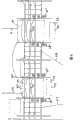
Fig. 3 schematically illustrates the useful structure according to the converter in the current conversion station of the present invention.This converter illustrates from an end, so only illustrate one that arranges in three row of embarking on journey.Thereby this is 12 pulse bridge converter, and it has four converter valve 11~14 that are connected in series in top of each other that are arranged to row.Like this be listed in to be illustrated here by the roof 19 of insulating element 20 with respect to valve hall is insulated.The DC side of converter is connected to described converter column at the opposite side of described converter column, arrives the utmost point of HVDC power transmission line by connecting 21, and arrives the neutral bus of current conversion stations by connection 22.The surge arrester 23~26 that is connected in series between described DC connects 21,22, a surge arrester and each converter valve are connected in parallel, and avoid overvoltage to protect converter valve.Two 23 and 24 sides that are arranged in converter valve column in a part in the surge arrester that is connected in series that is the surge arrester, another part then is arranged in the opposite side of these row, these two parts are by line 27 interconnection, described line 27 by the free space 28 between two described converter valve 12,13 from side guiding opposite side.Described line is formed by guide rail, cable etc.Each converter valve comprises a plurality of overlapping layers that comprise power semiconductor, and described free space 28 preferably forms by half that makes that two distances between the converter valve in succession are approximately such layer.
Show and be connected in succession how the parts 17 that are connected in series a little of the converter valve between the converter valve can be arranged in the opposite side 30,31 of converter in this way,, and produce above-mentioned advantage so that be connected to transformer 18 at the opposite side of converter.
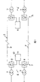
Fig. 4 schematically illustrates the part of current conversion station according to an embodiment of the invention.This current conversion station has four converters, and be used for illustrating in the accompanying drawings at the neutral bus of described DC neutral arrangement and valve hall 40,41 with two converters that are connected in series between the utmost point 4 of positive polarity, and two further this valve hall are arranged into these left side, as seeing in the accompanying drawings, between the negative polarity pole (not shown) of described neutral bus 42 and power transmission line, be arranged to corresponding layout.Converter in first valve hall 40 is configured to produce the voltage of about 400kV between the output 43 of converter and described neutral bus 42, the converter of another valve hall 41 then is configured to the voltage between the described utmost point 4 and the neutral bus 42 is brought up to about 800kV.
Show how with three Y transformers 18 " be arranged in a side of each valve hall and be connected to converter, and how with Δ transformer 18 " ' be arranged in the opposite side of valve hall and be connected to converter.The conductive guide 45 on the roof 46 by extending across valve hall, interconnection belongs to the Y transformer and the Δ transformer of same converter.Schematically illustrate and how AC line 47,48 is connected to current conversion station by being connected to these transformers.
Under following situation, each converter is a self-supporting: it has the control appliance that separates 49,50 of the operation that is configured to control converter, be used for providing the device (with shown in Figure 5 and discuss below) of auxiliary power to converter, and the device 51,52 of overall work situation as cooling off its parts that is used to control converter.This also makes can arrange sizable space between valve hall 40,41,50m or bigger for example, reduce when such converter valve hall suffers fire etc. more than the affected risk of one building, thereby electric power and economic loss are minimized.
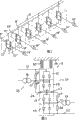
Fig. 5 schematically illustrates the general structure of current conversion station according to an embodiment of the invention.The valve hall 60,61 that is connected between the negative pole of neutral bus and HVDC power transmission line here also is illustrated.Current conversion station comprises the accessory power supply that separates 71~74 that is used for each converter 100~103, and under following situation, these accessory power supplys are connected to conduct stand-by power supply each other: break down if distribute to the accessory power supply of a converter, the accessory power supply of then distributing to other any converter is connected to also and transmits auxiliary power to described converter, provides redundant by remaining accessory power supply simultaneously.In the power supply two 72, the 73rd, the electric power networks of the operation by being independent of transmission system is connected to the external power source of current conversion station, and two 71,74 in the power supply then is the power supply that comprises in the current conversion station.Accessory power supply is configured to have the voltage of about 10kV, and each converter has its 10kV switching device 75~78, is used for the further low voltage distribution within the converter.Also can continue under the situation of any one interruption in being connected to the accessory power supply chamber of converter to transmit auxiliary power even this means to converter.
Further show each converter and how to have converter valve cooling device 80, be used to cool off the transformer that is associated with these valves equipment 81, be used for valve hall is ventilated and the device 82, the battery charger 83 that throw light on and be used for equipment 84 that the service building thing is heated and ventilates.
Current conversion station also comprises change of current station 90, and change of current station 90 has current conversion station battery charger 91 and the heating of current conversion station control room, ventilation and lighting apparatus 92.
Certainly, in any case the present invention is not limited to the above embodiments, clearly, those skilled in the art can carry out many modifications, and the basic thought of the present invention that does not break away from claims and limited.
For example, current conversion station can have the valve hall more than two between the neutral bus and the utmost point.It is equally clear that current conversion station can be connected to the HVDC power transmission line that only has a utmost point.
Claims (16)
1. current conversion station that is used for the AC system is connected to HVDC power transmission line (3), described current conversion station comprises at least two converters (8,9), it is arranged in valve hall (40 separately, 41,60,61) in, and each converter has the DC side and the AC side that is used to be connected described AC system (6) that is used to connect described power transmission line, described current conversion station comprises: the control appliance that is configured to control the operation of described converter, be used to described converter that the device of auxiliary power is provided, and be used to control the overall work situation of described converter as cooling off the device of its parts
It is characterized in that, described control appliance comprises control device (49 separately, 50), be used for controlling each converter of described current conversion station, described current conversion station has and is used to each converter that the device that separates (71~74) of auxiliary power is provided, for each converter layout is used to control the device that separates of overall work situation so that each converter self-supporting, and the device that utilizes each described control device and arrange explicitly with each valve hall, make described valve hall (40,41,60,61) be separated sizable space between.
2. current conversion station according to claim 1, it is characterized in that, described current conversion station has at least three described converters, in the described converter each is arranged in valve hall (40 separately, 41,60,61) in, described current conversion station comprises at least and the as many accessory power supply that separates of the number of converter (71~74), each converter is assigned with an accessory power supply that separates, and under following situation, these accessory power supplys are connected to conduct stand-by power supply each other: break down if distribute to the accessory power supply of a converter, the accessory power supply of then distributing to other any converter is connected to also and transmits auxiliary power to a described converter, provides redundant by remaining one or more accessory power supply simultaneously.
3. current conversion station according to claim 2 is characterized in that, described current conversion station has four converters (100~103) and is used as four described accessory power supplys (71~74) of stand-by power supply each other.
4. current conversion station according to claim 3, it is characterized in that two (72,73) in the described accessory power supply are the external power sources that is connected to described current conversion station by the electric power networks of the operation that is independent of described transmission system, two (71,74) are the power supplys that comprises in the described current conversion station.
5. according to each the described current conversion station in the claim 2~4, it is characterized in that described accessory power supply (71~74) is configured to have the voltage of 5kV~15kV such as about 10kV.
6. current conversion station according to claim 3, it is characterized in that, described current conversion station has two described converters (100 between the neutral bus (42) of the positive polarity utmost point (4) that is connected in series in described power transmission line and ground connection, 101), and be connected in series in the negative polarity pole (5) of described power transmission line and two the described converters (102,103) between the described neutral bus.
7. according to each the described current conversion station in the aforementioned claim, it is characterized in that, each described converter comprises: a plurality of converter valve (11~14) that are connected in series, and a plurality of links (17), described a plurality of link (17) is by being connected respectively to the AC side that the described point that is connected in series between the described converter valve in succession is connected to described converter, be used for being drawn out to transformer (18) from described valve hall, and each described converter is at two opposite sides (30 of described converter valve, 31) both sides in all comprise described link (17), thereby and comprise transformer at the opposite side of described valve hall.
8. current conversion station according to claim 7 is characterized in that, belongs to the side that half in the described transformer of each converter (18 ") is arranged in described valve hall, and half (18 ") is arranged in the opposite side of described valve hall.
9. according to claim 7 or 8 described current conversion stations, it is characterized in that, each described converter comprises the described converter valve of described at least four of being connected in series (11~14) in the top of each other that are arranged to row, and the described link (17) of AC side is connected between per two converter valve the point as being connected in series as described between first converter valve and second converter valve, between the 3rd converter valve and the 4th converter valve or the like.
10. current conversion station according to claim 9, it is characterized in that, for each described converter, being connected in series of described converter valve has four converter valve (11~14) thereby and each side in two opposite sides of described row and at the described link (17) that is used for the AC side of the opposite side (30,31) of described valve hall.
11. according to each the described current conversion station in the claim 7~10, it is characterized in that, each converter in the described current conversion station comprises four converter valve (11~14) that are connected in series of three described row, these three described row are arranged and are embarked on journey and be connected in parallel with each other, and each side that whenever is listed in two opposite sides (30,31) of described row has a described link (17) that is connected to described AC side.
12. according to each the described current conversion station in the claim 7~11, it is characterized in that, each converter in the described current conversion station comprises a plurality of surge arresters (23~26), its mode that is connected in parallel with a surge arrester and each converter valve (11~14) is connected in series between two DC side ends that are connected in series of described converter valve, being connected in series of described surge arrester has the first (23 of a side that is connected in series that is arranged in described converter valve, 24) and be arranged in the second portion in succession (25 of the opposite side that is connected in series of described converter valve, 26), and described two parts are by line (27) interconnection, and described line (27) is by two described converter valve (12,13) free space between (28) is from side guiding opposite side.
13. current conversion station according to claim 12, it is characterized in that, for each converter in the described current conversion station, each converter valve (11~14) comprises a plurality of overlapping layers that comprise power semiconductor, forms described free space (28) by half or described layer that makes two distances between the described converter valve (12,13) in succession be approximately described layer.
14. according to each the described current conversion station in the claim 7~13, it is characterized in that, each converter has the Y transformer that is connected to described link (18 ") in a side of described valve hall (40,41); and have the Δ transformer that is connected to described link (18 " ') at the opposite side of described valve hall (40,41), and the conductor (45) on described Y transformer and the described Δ transformer roof (46) by extending across described valve hall and being interconnected.
15. according to each the described current conversion station in the aforementioned claim, it is characterized in that, described current conversion station is configured to the AC system is connected to the HVDC power transmission line, the utmost point and the voltage between the ground that described HVDC power transmission line is configured to it surpass 200kV, preferably surpass 500kV, more preferably 600kV~1500kV, and 600kV~1000kV most preferably.
16. a HVDC (high voltage direct current) transmission system, it has according to each described at least one current conversion station in the claim 1~15.
Applications Claiming Priority (2)
| Application Number | Priority Date | Filing Date | Title |
|---|---|---|---|
| US75956406P | 2006-01-18 | 2006-01-18 | |
| US60/759,564 | 2006-01-18 |
Publications (1)
| Publication Number | Publication Date |
|---|---|
| CN101297456A true CN101297456A (en) | 2008-10-29 |
Family
ID=38287891
Family Applications (1)
| Application Number | Title | Priority Date | Filing Date |
|---|---|---|---|
| CNA2006800400008A Pending CN101297456A (en) | 2006-01-18 | 2006-06-15 | A converter station |
Country Status (7)
| Country | Link |
|---|---|
| US (1) | US8098504B2 (en) |
| EP (1) | EP1974432A4 (en) |
| CN (1) | CN101297456A (en) |
| BR (1) | BRPI0621418A2 (en) |
| RU (1) | RU2397590C2 (en) |
| WO (1) | WO2007084036A1 (en) |
| ZA (1) | ZA200805661B (en) |
Cited By (2)
| Publication number | Priority date | Publication date | Assignee | Title |
|---|---|---|---|---|
| CN103986152A (en) * | 2014-04-18 | 2014-08-13 | 浙江省电力设计院 | Method for arranging connecting area and valve hall power distribution unit of flexible DC converter station |
| CN111656637A (en) * | 2018-01-30 | 2020-09-11 | Abb电网瑞士股份公司 | Surge arrester dimensioning in a DC power transmission system |
Families Citing this family (14)
| Publication number | Priority date | Publication date | Assignee | Title |
|---|---|---|---|---|
| RU2396665C2 (en) † | 2006-01-20 | 2010-08-10 | Абб Текнолоджи Лтд. | Converter |
| CN101726640B (en) * | 2009-12-23 | 2012-09-05 | 中国电力科学研究院 | Control and protection system of converter valve operating test device |
| US9197068B2 (en) | 2010-09-30 | 2015-11-24 | Abb Research Ltd. | Coordinated control of multi-terminal HVDC systems |
| CN102486517B (en) * | 2010-12-01 | 2015-11-25 | 中国电力科学研究院 | The high voltage direct current transmission converter valve fault current testing method of surge voltage compound |
| CN102486500B (en) * | 2010-12-01 | 2014-10-01 | 中国电力科学研究院 | Impulse voltage compounded high-voltage direct-current power transmission converter valve fault current test device |
| CN103513650B (en) * | 2013-09-24 | 2015-12-02 | 许继电气股份有限公司 | The record ripple control method of converter valve opertaing device |
| KR101555498B1 (en) * | 2013-12-30 | 2015-09-24 | 주식회사 효성 | Power supply for high voltage direct current controller |
| CN104600738B (en) * | 2015-01-21 | 2017-02-22 | 南京南瑞继保电气有限公司 | Control device for high-voltage DC transmission series valve set |
| CN106877372B (en) * | 2017-03-01 | 2023-08-18 | 中国电力工程顾问集团中南电力设计院有限公司 | Flexible direct-current back-to-back converter station valve hall arrangement structure |
| CN107093890B (en) | 2017-06-02 | 2019-03-08 | 南京南瑞继保电气有限公司 | A kind of flexible direct current converter station internal fault switchgear distribution and sweep-out method |
| CN111373648A (en) * | 2017-11-22 | 2020-07-03 | 西门子股份公司 | Energy transmission via a bipolar HVDC transmission line |
| CN108647396B (en) * | 2018-04-13 | 2020-11-13 | 中国南方电网有限责任公司超高压输电公司检修试验中心 | Key equipment fault risk assessment method for improving reliability of converter valve |
| CN108683207B (en) * | 2018-05-28 | 2021-10-01 | 南京南瑞继保电气有限公司 | Online switching circuit, switching method and device for hybrid direct current converter valve bank |
| CN111122312B (en) * | 2018-10-30 | 2023-12-12 | 中国电力科学研究有限公司 | Measuring device for ultimate bearing capacity of lightning arrester hardware fitting |
Family Cites Families (8)
| Publication number | Priority date | Publication date | Assignee | Title |
|---|---|---|---|---|
| US395221A (en) | 1888-12-25 | Hasp-lock | ||
| DE3573690D1 (en) * | 1984-07-04 | 1989-11-16 | Bbc Brown Boveri & Cie | Method for the reduction of dynamic overvoltages in an alternating current grid system |
| SE463953B (en) | 1989-06-19 | 1991-02-11 | Asea Brown Boveri | INSTALLATION FOR DRAINING ELECTRIC POWER FROM A HIGH-SPEED DC POWER TRANSMISSION LINE |
| JPH04355628A (en) | 1991-05-31 | 1992-12-09 | Toshiba Corp | Dc transmission line short circuit detector |
| SE505746C2 (en) | 1995-04-07 | 1997-10-06 | Asea Brown Boveri | Protective equipment at a bipolar inverter station |
| SE515105C2 (en) * | 1998-12-18 | 2001-06-11 | Abb Ab | Method and apparatus for locating a cable in a DC connection |
| US6853541B2 (en) | 2002-06-25 | 2005-02-08 | Siemens Aktiengesellschaft | Compact converter station |
| AU2003299537A1 (en) * | 2002-09-18 | 2004-06-07 | Sure Power Corporation | Dc power system for marine vessels |
-
2006
- 2006-06-14 US US12/161,385 patent/US8098504B2/en not_active Expired - Fee Related
- 2006-06-15 CN CNA2006800400008A patent/CN101297456A/en active Pending
- 2006-06-15 BR BRPI0621418-5A patent/BRPI0621418A2/en not_active Application Discontinuation
- 2006-06-15 EP EP06747906A patent/EP1974432A4/en not_active Withdrawn
- 2006-06-15 WO PCT/SE2006/000713 patent/WO2007084036A1/en active Application Filing
- 2006-06-15 RU RU2008133583/09A patent/RU2397590C2/en not_active IP Right Cessation
-
2008
- 2008-06-27 ZA ZA200805661A patent/ZA200805661B/en unknown
Cited By (5)
| Publication number | Priority date | Publication date | Assignee | Title |
|---|---|---|---|---|
| CN103986152A (en) * | 2014-04-18 | 2014-08-13 | 浙江省电力设计院 | Method for arranging connecting area and valve hall power distribution unit of flexible DC converter station |
| CN103986152B (en) * | 2014-04-18 | 2016-04-27 | 浙江省电力设计院 | The method for arranging of flexible direct current converter station connection district and valve Room power distribution equipment |
| CN111656637A (en) * | 2018-01-30 | 2020-09-11 | Abb电网瑞士股份公司 | Surge arrester dimensioning in a DC power transmission system |
| CN111656637B (en) * | 2018-01-30 | 2021-07-16 | Abb电网瑞士股份公司 | Neutral device, converter station and direct current power transmission system |
| US11355925B2 (en) | 2018-01-30 | 2022-06-07 | Hitachi Energy Switzerland Ag | System design solution for DC grid cost reduction and risk minimization |
Also Published As
| Publication number | Publication date |
|---|---|
| EP1974432A4 (en) | 2010-07-07 |
| WO2007084036A8 (en) | 2008-11-06 |
| ZA200805661B (en) | 2009-04-29 |
| BRPI0621418A2 (en) | 2011-12-06 |
| US20090168473A1 (en) | 2009-07-02 |
| EP1974432A1 (en) | 2008-10-01 |
| US8098504B2 (en) | 2012-01-17 |
| RU2008133583A (en) | 2010-02-27 |
| RU2397590C2 (en) | 2010-08-20 |
| WO2007084036A1 (en) | 2007-07-26 |
Similar Documents
| Publication | Publication Date | Title |
|---|---|---|
| CN101297456A (en) | A converter station | |
| US8872377B2 (en) | Autotransformer traction power supply system equipped with 2×27.5kV outdoor modularized electric apparatus in electrified railway | |
| CN102668305B (en) | Battery energy storage system with short circuit protection, and method | |
| RU2396664C2 (en) | Converting substation | |
| US9172248B2 (en) | Cascaded converter station and cascaded multi-terminal HVDC power transmission system | |
| CN203504285U (en) | UPS integrated power supply | |
| US20130050888A1 (en) | High voltage dc switchyard with semiconductor switches | |
| RU2484571C1 (en) | Electric energy transmission system | |
| RU2596046C1 (en) | Alternate current traction substation for supply of traction loads 25 kv | |
| CN107809069A (en) | A kind of moving emergency power cabinet for the bypass of power network low-voltage equipment | |
| CN107482523B (en) | Double bus scheme GIS device and its repair method, pressure resistant test method | |
| CN104218460A (en) | 220kv side wiring structure of 500kv high capacity transformer station | |
| RU2219631C1 (en) | Modular distribution transformer substation | |
| CN111668783B (en) | Special-shaped HGIS equipment, electrical main wiring and transformer substation | |
| CN211907960U (en) | 500kV-220kV composite substation | |
| CN210404741U (en) | Power transmission system | |
| CN210183012U (en) | Power transmission system | |
| CN113572189A (en) | Bipolar flexible direct current system for offshore wind power and transformer fault switching method thereof | |
| CN202264649U (en) | Network side circuit of motor train unit | |
| CN204156314U (en) | The 220kv side joint line structure of 500kv Large Copacity transformer station | |
| Sau-Bassols et al. | Technical feasibility of Power Flow Controllers for HVDC grids | |
| CN218352256U (en) | Power standby power supply circuit for extra-high voltage converter station | |
| CN214479622U (en) | Power distribution system | |
| KR100833691B1 (en) | Power supply system and method by distributed switching system | |
| CN217227346U (en) | Rail transit traction power supply device and rail transit traction power supply system |
Legal Events
| Date | Code | Title | Description |
|---|---|---|---|
| C06 | Publication | ||
| PB01 | Publication | ||
| C10 | Entry into substantive examination | ||
| SE01 | Entry into force of request for substantive examination | ||
| C02 | Deemed withdrawal of patent application after publication (patent law 2001) | ||
| WD01 | Invention patent application deemed withdrawn after publication |
Open date: 20081029 |