CN101296526B - Railway special network communication system based on passive optical network - Google Patents

Railway special network communication system based on passive optical network Download PDF

Info

Publication number
CN101296526B
CN101296526B CN2008100170666A CN200810017066A CN101296526B CN 101296526 B CN101296526 B CN 101296526B CN 2008100170666 A CN2008100170666 A CN 2008100170666A CN 200810017066 A CN200810017066 A CN 200810017066A CN 101296526 B CN101296526 B CN 101296526B
Authority
CN
China
Prior art keywords
equipment
monitoring point
site apparatus
railway
communication system
Prior art date
Legal status (The legal status is an assumption and is not a legal conclusion. Google has not performed a legal analysis and makes no representation as to the accuracy of the status listed.)
Expired - Fee Related
Application number
CN2008100170666A
Other languages
Chinese (zh)
Other versions
CN101296526A (en
Inventor
王洪君
冯桂文
王伟
杨华
Current Assignee (The listed assignees may be inaccurate. Google has not performed a legal analysis and makes no representation or warranty as to the accuracy of the list.)
Shandong University
Original Assignee
Shandong University
Priority date (The priority date is an assumption and is not a legal conclusion. Google has not performed a legal analysis and makes no representation as to the accuracy of the date listed.)
Filing date
Publication date
Application filed by Shandong University filed Critical Shandong University
Priority to CN2008100170666A priority Critical patent/CN101296526B/en
Publication of CN101296526A publication Critical patent/CN101296526A/en
Application granted granted Critical
Publication of CN101296526B publication Critical patent/CN101296526B/en
Expired - Fee Related legal-status Critical Current
Anticipated expiration legal-status Critical

Links

Images

Abstract

The invention discloses a communication system for a special railway network based on a passive optical network. The problems that the existing communication system for the special railway network based on twisted-pair lines costs highly in maintenance, and is limited in bandwidth and incapable of meeting practical application, etc. are solved by the system which has the advantages of simple structure, low cost, enough bandwidth supply and practical application satisfaction, etc. The system is an ideal proposal for upgrading and reconstruction of the special railway network. The structure of the system is that: the system comprises at least 3 pieces of optical fiber circuits, wherein, one is a main trunk circuit used for the connection of exchange and transmission equipment between neighboring sites, and other two are provided with monitoring points of wiring posts arranged every 2Km, and passive optical couplers are arranged, thereby realizing the access of a railway patrol telephone and emergency communication equipment. A one-wavelength broadcast mode is adopted along the direction from site equipment to each monitoring point of a wiring terminal; and a wavelength division multiplex mode is adopted along the direction from the monitoring point of the wiring terminal to the site equipment, and communication between a plurality of monitoring points of the wiring terminal and the site equipment is permitted.

Description

Railway private network communication system based on EPON
Technical field
The invention belongs to technical field of optical fiber communication, is a kind of railway private network communication system based on EPON.
Background technology
Along with China's rapid economic development, railway transportation capability improves year by year, and the informationization of railway private network is had higher requirement.At present most of old rail track still adopts copper cash as transmission medium, message transmission bandwidth and limited transmission distance (SHDSL symmetry transmission system commonly used now, the information of transmission 2Mb/S bandwidth only can be transmitted about 13Km on the copper cash in 0.9mm line footpath, during transmission bandwidth 4~5Mb/s, distance only is several kilometers), the signal transmission quality instability for the bigger section of distance between sites, need be established a plurality of source stations that have.And As time goes on, aging circuit is serious, and maintenance cost is very high.These railway information communication lines are implemented the optical cable transformation, extremely urgent.
At present, some rail tracks adopt the GSMR system to form the railway private network communication, this mode cost of investment height, and limited bandwidth, and the dynamically emergent image Time Bandwidth of transmission is limited.The railway end that has some to lay optical fiber, optical cable generally also only are used for message transmission between the railway website, and daily line walking and emergency communication etc. are not also used basically.
Summary of the invention
Purpose of the present invention is exactly in order to solve present railway private network communication system maintenance cost height based on twisted-pair feeder, limited bandwidth, can't satisfy problems such as practical application, provide a kind of have simple in structure, cost is lower, enough bandwidth can be provided, satisfy the railway private network communication system based on EPON of advantages such as actual use.
For achieving the above object, the present invention adopts following technical scheme:
A kind of railway private network communication system based on EPON, its structure is: it comprises 3 optical fiber, article 1, be basic routing line, be used between the adjacent sites connection of exchange and transmission equipment, other 2 are provided with the binding post monitoring point every 2Km, place passive optical coupler, realize the access of railway patrol telephone and emergency communication equipment.Adopt the mode of 1 wavelength broadcasting to the direction of each binding post monitoring point at site apparatus; And adopt the mode of wavelength division multiplexing to the direction of site apparatus in the binding post monitoring point, allow several binding posts monitoring point to communicate by letter with site apparatus simultaneously.
Described site apparatus comprises wavelength division multiplexer, between wavelength division multiplexer and audio frequency, video data processing module, an optical link sending module is arranged, several optical link receiver modules, audio frequency, video data processing module are landed Ethernet data signal, vision signal, audio signal.
Described railway patrol telephone is through passive optical coupler incoming light ray road, is connected to SPC telephone exchange through several FXO interfaces of site apparatus, thereby realizes the phone line walking.
Described emergency communication equipment is by passive optical coupler incoming light ray road, after adjacent site apparatus is handled, by arriving Police Command Center equipment after the exchange of each site apparatus and the optical transmission device relay transmission in the transmission equipment, in Police Command Center equipment, recover audio frequency, video and data-signal.
Described Police Command Center equipment comprises Ethernet switch, and it is connected with video server by Ethernet, is connected to stored-program control exchange through Softswitch, Tandem Gateway simultaneously; Ethernet switch also directly transmits Ethernet data simultaneously.
Described exchange and transmission equipment comprise 3 layers of Ethernet switch, fiber optical transceiver or SDH transmission equipment.
Railway private network communication system based on EPON of the present invention, passive optical coupler is adopted in its binding post monitoring point, adopts the mode of 1 wavelength broadcasting to the direction of each binding post monitoring point at website; And can adopt the mode of wavelength division multiplexing to the direction of website in the binding post monitoring point, allow several binding posts monitoring point to communicate by letter with site apparatus simultaneously.The 40Km section need not active relaying, and the 80Km section only needs 1 active relay station.Being applied to application of railway patrol telephone and emergency communication uses.
The present invention adopts EPON and wavelength-division multiplex technique, place passive optical coupler in each binding post monitoring point, distance between two binding post monitoring points is 2Km, and 19 optical couplers are arranged on the 40Km section like this, and 39 optical couplers are arranged on the 80Km section.During communication, adopt the mode of 1 wavelength broadcasting to the direction of each binding post monitoring point at website; And can adopt the mode of wavelength division multiplexing to the direction of website in the binding post monitoring point, allow several binding posts monitoring point to communicate by letter with site apparatus simultaneously.
For the 40Km section, 19 couplers are arranged, if the employing splitting ratio is 90/10 coupler, then last 1 optical coupler to the total insertion loss of 19 optical couplers of equipment between the station is 19 * 0.62=11.78dB, equipment is that the insertion loss that 10 knee-joint is gone into is: 12dB, the loss 40 * 0.3=12dB of 40Km optical fiber by splitting ratio.Total losses are: 11.78+12+12=35.78dB.If the equipment of site apparatus and binding post monitoring point all adopts the optical module of DFB, then transmitting power can reach+2dBm, the receiving sensitivity of light-receiving when transmission rate is 125Mb/S (PIN/FET) module can reach-38dBm, this shows to need not to use active relay station on the section of 40Km.For section, need to use active relay station, because the section distance can be greater than 80Km, so at most only need 1 active relay station greater than 40Km.
The invention has the beneficial effects as follows: system constitutes simple, and cost is lower, and enough bandwidth can be provided, and satisfies present railway private network upgrading actual needs.The 40Km section need not active relay station, and the 80Km section only needs 1 active relay station, and it is convenient to implement.
Description of drawings
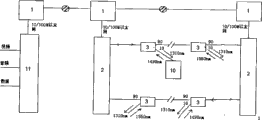
Fig. 1 is a system principle diagram of the present invention;
Fig. 2 is the site apparatus theory diagram;
Fig. 3 is a patrol telephone application principle block diagram;
Fig. 4 is an emergency communication application principle block diagram;
Fig. 5 is an emergency communication command centre device structure block diagram.
Wherein, 1. the exchange and transmission equipment, 2. site apparatus, 3. passive optical coupler, 4. wavelength division multiplexer, 5. audio frequency, video data processing module, 6. optical link receiver module, 7. optical link sending module, 8. patrol telephone, 9. SPC telephone exchange, 10. emergency communication equipment, 11. Police Command Center equipment, 12. Ethernet switch, 13. Softswitch, 14. Tandem Gateways, 15. video servers.
Embodiment
The present invention will be further described below in conjunction with accompanying drawing and embodiment.
System architecture and theory diagram are seen Fig. 1.It comprises several exchanges and the transmission equipment 1 that is arranged on the basic routing line, each exchange and transmission equipment 1 corresponding site apparatus 2, pass through an optical fiber communication 2 of adjacent sites equipment, on other two optical fiber, be provided with several binding post monitoring points, the binding post test point adopts passive optical coupler 3, adopts the mode of at least 1 wavelength broadcasting to the direction of each binding post monitoring point at site apparatus 2; And adopt the mode of wavelength division multiplexing to the direction of site apparatus 2 in the binding post monitoring point, allow several binding posts monitoring point to communicate by letter with site apparatus 2 simultaneously; The binding post monitoring point also is connected with railway patrol telephone 8 and emergency communication equipment 10 simultaneously.
If the equipment of site apparatus 2 and binding post monitoring point all adopts the optical module of DFB, then on the section of 40Km, need not to use active relay station, the 80Km section only needs 1 active relay station.
Among Fig. 2, site apparatus 2 comprises wavelength division multiplexer 4, and it is connected with audio frequency, video data processing module 5 by the light Transmit-Receive Unit, and audio frequency, video data processing module 5 are landed Ethernet data signal, vision signal, audio signal; 1 optical link sending module 7 is arranged, several optical link receiver modules 6 at wavelength division multiplexer 4 and audio frequency, 5 of video data processing modules.
The wavelength optical signals that each binding post monitoring point is come arrives corresponding light receiving unit behind wavelength division multiplexer, arrive audio frequency, video and data processing unit behind each light receiving unit, recovers audio frequency, video and data-signal.Website adopts the mode of a wavelength (1310nm) broadcasting to each binding post monitoring point direction, audio frequency, video and 10/100M Ethernet data signal are sent into the light transmitting element after treatment, go into optical link and are sent to each binding post monitoring point through wavelength division multiplexer is laggard then.
Among Fig. 3, railway patrol telephone 8 is connected to the SPC telephone exchange 9 of exchange and transmission equipment 1 through passive optical coupler 3 incoming light ray roads through several FXO interfaces of site apparatus 2, thereby realizes the phone line walking.
Among Fig. 4, emergency communication equipment 10 is by passive optical coupler 3 incoming light ray roads, after adjacent site apparatus 2 is handled, by arriving Police Command Center equipment 11 after the exchange of each site apparatus 2 and the optical transmission device relay transmission in the transmission equipment 1, in Police Command Center equipment 11, recover audio frequency, video and data-signal.
Among Fig. 5, Police Command Center equipment 11 comprises Ethernet switch 12, and it is connected with video server 15 by Ethernet, connects stored-program control exchange through Softswitch 13, Tandem Gateway 14 simultaneously; Ethernet switch 12 also directly transmits Ethernet data simultaneously.
Exchange and transmission equipment 1 comprise 3 layers of Ethernet switch, fiber optical transceiver or SDH transmission equipment.

Claims (4)

1. railway private network communication system based on EPON, it is characterized in that, it comprises 3 optical fiber, article 1, be basic routing line, be used between the adjacent sites connection of exchange and transmission equipment, other 2 are provided with the binding post monitoring point every 2Km, place passive optical coupler, realize the access of railway patrol telephone and emergency communication equipment; Adopt the mode of 1 wavelength broadcasting to the direction of each binding post monitoring point at site apparatus; And adopt the mode of wavelength division multiplexing to the direction of site apparatus in the binding post monitoring point, and allow several binding posts monitoring point to communicate by letter with site apparatus simultaneously, the binding post monitoring point also is connected with railway patrol telephone and emergency communication equipment simultaneously;
Described site apparatus comprises wavelength division multiplexer, and wavelength division multiplexer is connected with audio frequency, video data processing module by the light Transmit-Receive Unit; Described smooth Transmit-Receive Unit is an optical link sending module and several optical link receiver module between wavelength division multiplexer and audio frequency, video data processing module, and audio frequency, video data processing module are landed Ethernet data signal, vision signal, audio signal; Described railway patrol telephone is through passive optical coupler incoming light ray road, is connected to SPC telephone exchange through several FXO interfaces of site apparatus, thereby realizes the phone line walking.
2. the railway private network communication system based on EPON as claimed in claim 1, it is characterized in that, described emergency communication equipment is by passive optical coupler incoming light ray road, after adjacent site apparatus is handled, by arriving Police Command Center equipment after the exchange of each site apparatus and the optical transmission device relay transmission in the transmission equipment, in Police Command Center equipment, recover audio frequency, video and Ethernet data signal.
3. the railway private network communication system based on EPON as claimed in claim 2, it is characterized in that, described Police Command Center equipment comprises Ethernet switch, and it is connected with video server by Ethernet, is connected to stored-program control exchange through Softswitch, Tandem Gateway simultaneously; Ethernet switch also directly transmits Ethernet data simultaneously.
4. the railway private network communication system based on EPON described in claim 1 or 2 is characterized in that described exchange and transmission equipment comprise 3 layers of Ethernet switch, fiber optical transceiver or SDH transmission equipment.
CN2008100170666A 2008-06-25 2008-06-25 Railway special network communication system based on passive optical network Expired - Fee Related CN101296526B (en)

Priority Applications (1)

Application Number Priority Date Filing Date Title
CN2008100170666A CN101296526B (en) 2008-06-25 2008-06-25 Railway special network communication system based on passive optical network

Applications Claiming Priority (1)

Application Number Priority Date Filing Date Title
CN2008100170666A CN101296526B (en) 2008-06-25 2008-06-25 Railway special network communication system based on passive optical network

Publications (2)

Publication Number Publication Date
CN101296526A CN101296526A (en) 2008-10-29
CN101296526B true CN101296526B (en) 2011-04-13

Family

ID=40066455

Family Applications (1)

Application Number Title Priority Date Filing Date
CN2008100170666A Expired - Fee Related CN101296526B (en) 2008-06-25 2008-06-25 Railway special network communication system based on passive optical network

Country Status (1)

Country Link
CN (1) CN101296526B (en)

Families Citing this family (1)

* Cited by examiner, † Cited by third party
Publication number Priority date Publication date Assignee Title
CN107171715B (en) * 2017-05-31 2023-10-31 中铁第四勘察设计院集团有限公司 Railway signal data network system and connection method thereof

Citations (4)

* Cited by examiner, † Cited by third party
Publication number Priority date Publication date Assignee Title
US5606555A (en) * 1994-05-20 1997-02-25 Siemens Aktiengesellschaft Apparatus and method for operating and constructing an optical TDM/TDMA system having enhanced range
CN101009530A (en) * 2006-01-23 2007-08-01 华为技术有限公司 Passive optical network, multiplexing/de-multiplexing device and method supporting the multicast service
CN101162941A (en) * 2006-10-13 2008-04-16 日立通讯技术株式会社 Apparatus of adjusting optical signal transmission timing
CN201226519Y (en) * 2008-06-25 2009-04-22 山东大学 Communication system for railway special network based on passive optical network

Patent Citations (4)

* Cited by examiner, † Cited by third party
Publication number Priority date Publication date Assignee Title
US5606555A (en) * 1994-05-20 1997-02-25 Siemens Aktiengesellschaft Apparatus and method for operating and constructing an optical TDM/TDMA system having enhanced range
CN101009530A (en) * 2006-01-23 2007-08-01 华为技术有限公司 Passive optical network, multiplexing/de-multiplexing device and method supporting the multicast service
CN101162941A (en) * 2006-10-13 2008-04-16 日立通讯技术株式会社 Apparatus of adjusting optical signal transmission timing
CN201226519Y (en) * 2008-06-25 2009-04-22 山东大学 Communication system for railway special network based on passive optical network

Non-Patent Citations (1)

* Cited by examiner, † Cited by third party
Title
黄庆贵.接入网在铁路通信中的应用.铁路通信信号2000年.2000,36(3),2-4. *

Also Published As

Publication number Publication date
CN101296526A (en) 2008-10-29

Similar Documents

Publication Publication Date Title
RU2667686C1 (en) High-speed network long communication system
CN101166064A (en) Conversion device for RF remote distribution system in communication system
CN106210668A (en) Web-transporting device based on EOC
CN101364842B (en) Apparatus and system prolonging transmission distance of passive optical network
CN101389057B (en) Railway communication method and system
CN101296526B (en) Railway special network communication system based on passive optical network
CN106791705A (en) A kind of simple and direct tunnel HD video of low cost changes system
CN201226519Y (en) Communication system for railway special network based on passive optical network
AU2018236894B9 (en) PON system and communication control method
CN103269318A (en) IP (Internet Protocol) multicasting signal method of OTN (Optical Transport Network) broadcast
CN105790839A (en) Optical fiber system and method based on wavelength division multiplexing light-free relay
RU2753987C1 (en) Telecommunications access system for railway infrastructure facilities on the railway section to station equipment
CN105071857B (en) Optical transmission system is relayed on cascade multi-span tower
CN101072330A (en) Closed circuit television monitoring system signal transmission method
CN102082978A (en) Railway interval broadband communication system based on EPON (Ethernet passive optical network), devices and method
CN206164721U (en) Web -transporting device based on EOC
CN104852767B (en) A kind of optical network system and transmission method towards sampled value business in substation
CN203151693U (en) Broadcasting system composed of OTN network and data network
CN202282835U (en) Lossless relay multiplexer for digital videos
CN207819937U (en) A kind of OTNEPON plug-in cards
RU2381939C1 (en) System of technological radio communication through digital channels of communication in railroad (versions)
CN101026420B (en) Method and system for solving FTTP safety problem
CN115765853A (en) Transmission device and method of redundant data
CN201533327U (en) Optical voice call through optical fiber transmission at railway sections
JPH0319436A (en) Optical subscriber system

Legal Events

Date Code Title Description
C06 Publication
PB01 Publication
C10 Entry into substantive examination
SE01 Entry into force of request for substantive examination
C14 Grant of patent or utility model
GR01 Patent grant
CF01 Termination of patent right due to non-payment of annual fee

Granted publication date: 20110413

Termination date: 20150625

EXPY Termination of patent right or utility model