CN101289022B - Liquid container - Google Patents
Liquid container Download PDFInfo
- Publication number
- CN101289022B CN101289022B CN2008100904443A CN200810090444A CN101289022B CN 101289022 B CN101289022 B CN 101289022B CN 2008100904443 A CN2008100904443 A CN 2008100904443A CN 200810090444 A CN200810090444 A CN 200810090444A CN 101289022 B CN101289022 B CN 101289022B
- Authority
- CN
- China
- Prior art keywords
- liquid
- detecting unit
- terminal
- liquid detecting
- liquid container
- Prior art date
- Legal status (The legal status is an assumption and is not a legal conclusion. Google has not performed a legal analysis and makes no representation as to the accuracy of the status listed.)
- Expired - Fee Related
Links
Images


Classifications
-
- B—PERFORMING OPERATIONS; TRANSPORTING
- B41—PRINTING; LINING MACHINES; TYPEWRITERS; STAMPS
- B41J—TYPEWRITERS; SELECTIVE PRINTING MECHANISMS, i.e. MECHANISMS PRINTING OTHERWISE THAN FROM A FORME; CORRECTION OF TYPOGRAPHICAL ERRORS
- B41J2/00—Typewriters or selective printing mechanisms characterised by the printing or marking process for which they are designed
- B41J2/005—Typewriters or selective printing mechanisms characterised by the printing or marking process for which they are designed characterised by bringing liquid or particles selectively into contact with a printing material
- B41J2/01—Ink jet
- B41J2/17—Ink jet characterised by ink handling
- B41J2/175—Ink supply systems ; Circuit parts therefor
- B41J2/17566—Ink level or ink residue control
Abstract
A liquid container includes a liquid containing portion, a case, a liquid detection unit, and an impact absorbing portion. The liquid containing portion contains liquid. The case forms a space that accommodates the liquid containing portion. The liquid detection unit includes a liquid introducing portion that is connected through an attachment portion, which is provided in the case, to a liquid delivery port of the liquid containing portion. The impact absorbing portion is provided at least between a bottom face of the case and the liquid detection unit to absorb an impact applied to the liquid detection unit.
Description
Technical field
The present invention relates to for example to be applicable to the liquid container of print cartridge that printer is used etc.
Background technology
Liquid injection apparatus as from the nozzle ejection liquid of jet head liquid had ink-jet printer in the past.Having that this ink-jet printer has carried beyond carriage print cartridge locational from frame type ink feeding system.Possess the situation of jumbo print cartridge and make the carriage miniaturization as having this situation, for example having, thereby ink-jet printer is done for a short time and thin situation or the like by not carrying print cartridge in order to open the paper printing greatly from frame type ink feeding system.Usually on print cartridge, carry the ink detection unit that is used to detect the ink surplus.For example in patent documentation 1, disclose from frame type print cartridge.
Patent documentation 1: the Japanese documentation spy opens the 2002-19136 communique.
Summary of the invention
The ink detection unit comprises sensors such as piezoelectric element, and the signal of telecommunication that is detected by sensor is stored in the memory element on the circuit board of lift-launch on print cartridge.The terminal of ink detection cell side and the fixed contact Elastic Contact on the circuit board are so that both keep reliable electrical contact.
But, if apply collision as dropping, the breakage of liquid detecting unit is arranged then to print cartridge, and then the danger that damages of sensor.
At this, the objective of the invention is to, comprised that the collision that applies as dropping can not make the liquid container of the structure of liquid detecting unit breakage yet even provide a kind of.
The liquid container that the present invention relates to is characterised in that, comprising:
Liquid containing portion accommodates liquid;
Framework is formed with the space that holds described liquid containing portion; And
The liquid detecting unit comprises via the liquid introduction part that is arranged at the installation portion on the described framework and engages with the liquid export mouth of described liquid containing portion,
At least between the bottom surface of described framework and described liquid detecting unit, be provided with the collision absorbent portion of absorption in the collision of described liquid detecting unit.
According to the present invention,, also can absorb the collision that applies to liquid container, thereby prevent the breakage of liquid detecting unit by colliding absorbent portion even applied collision as dropping to liquid container.
In the present invention, described liquid detecting unit is comprised: cell enclosure, remain on sensor and relaying terminal on the described cell enclosure, described relaying terminal comprises relay and is positioned at first and second terminal of described relay both end sides, described second terminal links to each other with described sensor, wherein, described cell enclosure comprises: the first terminal maintaining part keeps the described the first terminal of described relaying terminal; The second terminal maintaining part keeps described second terminal of described relaying terminal; And variant part, be arranged between described the first terminal maintaining part and the described second terminal maintaining part, come the collision of absorption in described liquid detecting unit by strain, described collision absorbent portion can contact with described liquid detecting unit between the described variant part of described liquid detecting unit and described liquid introduction part.
Thus, can collide absorption by being arranged at oneself variant part on one's body of liquid detecting unit, the deformation result in the variant part is: when the liquid detecting unit moves, can collide absorption by colliding absorbent portion.And, by the strain in variant part, can absorb collision to the sensor that links to each other with second terminal.
In the present invention, can make described liquid detecting unit between the described variant part of described liquid detecting unit and described liquid introduction part, comprise the liquid leading-out portion, described collision absorbent portion is arranged between the bottom surface of described liquid leading-out portion and described framework, between the described variant part and described liquid introduction part of described liquid detecting unit, except with described liquid leading-out portion that described collision absorbent portion contacts, described liquid detecting unit does not contact with the bottom surface side of described framework.
Because the position of the liquid leading-out portion of liquid container is required the positional precision when the main body of liquid injection apparatus etc. is installed, so the carrier of liquid leading-out portion need be set in the framework side.Collide absorbent portion by this carrier is used as, can absorb collision to the liquid detecting unit.Between the variant part and liquid introduction part of liquid detecting unit, except with collide the liquid leading-out portion that absorbent portion contacts, the liquid detecting unit does not contact with the bottom surface side of described framework.Therefore, impulsive contact force can not affact from the bottom surface of framework on the liquid detecting unit.
In the present invention, described collision absorbent portion can be formed by the material of the liquid that can absorb described liquid containing portion.
Thus, collide absorbent portion and can absorb the liquid of revealing from the liquid leading-out portion, thereby can prevent the fault of the sensor that causes by the liquid that leaks etc.
In the present invention, described collision absorbent portion can be paved with between the bottom surface of described liquid detecting unit and described framework in the described variant part and the zone between the described liquid introduction part of described liquid detecting unit.
In this case, absorbed collision by being paved with collision absorbent portion between the bottom surface of liquid detecting unit and framework to the effect of liquid detecting unit.And when having the liquid leading-out portion between the variant part of liquid detecting unit and liquid introduction part, colliding absorbent portion can be formed by the material of the liquid that can absorb liquid container.
In the present invention, the structure of described framework can comprise: the detecting unit accommodation section that holds described liquid detecting unit; Graduation described liquid containing portion and described detecting unit accommodation section, and be provided with the spaced walls of described installation portion; And with the described detecting unit of described spaced walls graduation accommodation section, and the sidewall of holding circuit plate, described liquid detecting unit is the center rotation with the installation portion of described framework, and on the rotation terminal position, described the first terminal contacts with fixed contact on the described circuit board.Because the liquid detecting unit engages with liquid containing portion in being built in liquid container, thereby when the liquid containing unit of keeping this joint being electrically connected or disconnect connection, rotary manipulation is most preferred.In the case, when collision acts on described liquid detecting unit, it is that the center is shaken near the zone of described liquid introduction part side with the installation portion of described framework also that described variant part can allow than described variant part, thereby absorption is in the collision of described liquid detecting unit.
In the present invention, described variant part also can be to the direction strain of shrinking the distance between described the first terminal maintaining part and the described second terminal maintaining part.
In this case, by making the variant part strain make the position withdrawal of the first terminal.If under this state, liquid detection sensor is installed on the liquid container etc., then can under the situation that the first terminal does not interfere with liquid container etc., make the first terminal arrive the electrically connecting position of regulation.Thereby the relaying terminal is difficult to deform etc., can reduce bad connection, and the fitting operation of liquid detecting unit also becomes easy.As long as make the variant part elastic recovery, just the first terminal can be electrically connected on the fixed contact of circuit board etc.That is, variant part can be held the function of colliding absorption function and oversimplifying the fitting operation of liquid detecting unit in the lump.
In the present invention, described variant part can comprise slit, makes described variant part strain, to dwindle the groove width of described slit.
So, as long as form slit, just can form variant part as the shape of cell enclosure.
In the present invention, described variant part can comprise: movable body, and the direction that extends with the described relay of described relaying terminal is arranged on described the first terminal maintaining part side across; Support, the direction that extends with the described relay of described relaying terminal is arranged on the described second terminal maintaining part, one side across, and is arranged with described movable body branch; And connecting portion, engage described movable body and described support.Thus, stipulate described slit by described movable body, described support and described connecting portion.The main purpose of this slit is in order to simplify the fitting operation of liquid detecting unit, also can be owing to the impulsive contact force that acts on the liquid detecting unit is out of shape but can assure.
Among the present invention, described the first terminal maintaining part can be arranged on the free end that the cardinal extremity that engages with described connecting portion from described movable body extends.Thus, can guarantee that the displacement of the first terminal maintaining part and then the first terminal is bigger, thereby improve the variant part function of simplifying the fitting operation of liquid detecting unit.
In the present invention, can be provided for applying the operating portion of the external force that makes described variant part distortion at the described free end of described movable body.Thus,, can make the variant part strain by operating operation portion, easy thereby the loading and unloading of liquid detecting unit will become.
In the present invention, described connecting portion can comprise: two riser portions of extending upward from each cardinal extremity that engages with described movable body and described support; And the junction surface that the upper end of described two riser portions is engaged with each other.Thus, can make described two riser portions bring into play function as the handle part that is used to apply the external force that makes described variant part distortion.
In addition, in the present invention, described connecting portion also can be formed by the elastomer of the individual components that separates with described cell enclosure.
In the present invention, described relaying terminal can be formed by metal thin plate, and described relay can comprise: first thin plate part that crosses described movable body and described support; And at the end of described first thin plate part warpage and second thin plate part that extends along described movable body.At this moment, described the first terminal is at the end of second thin plate part warpage and to outstanding formation of direction away from described movable body.Thus, the rigidity of the relay of relaying terminal improves by a plurality of joggling parts, moves thereby follow movable body easily.
In the present invention, described variant part can comprise the distortion guide portion, and this distortion guide portion is followed the distortion of described variant part and guided described first thin plate part distortion.Thus, the relaying terminal becomes higher to the followability of movable body.
In the present invention, described first thin plate part can comprise the rib that is reinforced along described support warpage.Thus, the rigidity of relaying terminal further improves, thereby makes the first terminal follow variant part and displacement easily.
In the present invention, described the first terminal maintaining part also can movably keep the described the first terminal of described relaying terminal, and the described the first terminal of described relaying terminal is highlighted biasing and is kept by described the first terminal maintaining part to the direction of described variant part strain.Thus, also can apply elastic pressure after the variant part elastic recovery to the first terminal.
In the present invention, described the first terminal can comprise and will be highlighted the slotted hole portion of the direction of biasing as length direction, and the first terminal maintaining part of described cell enclosure can comprise and inserts the jut that leads in described slotted hole portion.Thus, the first terminal movably can be remained on the first terminal maintaining part.
In the present invention, described framework can comprise the location division, and this location division positions described liquid detecting unit under the described the first terminal of described liquid detecting unit and state that described fixed contact links to each other.
In the present invention, described framework can comprise the location division, and this location division positions described liquid detecting unit under the described the first terminal of described liquid detecting unit and state that described fixed contact links to each other.Thus, can keep electrical connection.
In the present invention, described location division can keep the groove width of the slit of described variant part, so that it does not narrow down after described liquid detecting unit is installed.So, only otherwise apply excessive external force, just can keep the strong electrical connections of ability such as anti-vibration to variant part.
Description of drawings
Fig. 1 is the stereogram of the printer in the embodiment of the present invention;
Fig. 2 is the three-dimensional exploded view of printer shown in Figure 1;
Fig. 3 is the three-dimensional exploded view of print cartridge shown in Figure 1;
Fig. 4 is the cut-away view of print cartridge;
Fig. 5 is the outside drawing of print cartridge;
(A) of Fig. 6 is the partial plan that is equipped with the print cartridge of liquid detecting unit, and (B) of Fig. 6 is the enlarged drawing of the regional A1 of (A);
Fig. 7 is the side view that is equipped with the print cartridge of liquid detecting unit;
Fig. 8 is the part side view that is equipped with the print cartridge of circuit board;
(A) of Fig. 9 is the stereogram of print cartridge, and (B) of Fig. 9 inserts the enlarged drawing lead to the opening that interface uses;
Figure 10 is the three-dimensional exploded view of liquid detecting unit;
Figure 11 is the location key diagram of liquid detecting unit;
(A) of Figure 12 and (B) be the concise and to the point stereogram of the box main body of liquid detecting unit;
(A) of Figure 13 and (B) be the installation instructions figure of liquid detecting unit;
(A) of Figure 14 and (B) be the side view of liquid detecting unit;
Figure 15 is the location key diagram of liquid detecting unit;
(A) of Figure 16 and (B) be the stereogram of cell enclosure;
(A) of Figure 17 and (B) be the stereogram of cell enclosure;
(A) of Figure 18 and (B) be to be used to illustrate the stereogram that collides absorbent portion;
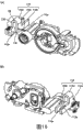
Figure 19 illustrates to having the framework of colliding absorbent portion the stereogram of the state of liquid detecting unit has been installed;
Figure 20 is the stereogram that is used to illustrate the collision absorbent portion different with Figure 18 (B);
Figure 21 is the stereogram that illustrates as the framework of the comparative example that does not collide absorbent portion.
The specific embodiment
Next, embodiments of the present invention are described.The present embodiment that the following describes is not to be used for limiting irrelevantly the content of the present invention put down in writing in claims, the formation that describes in the present embodiment and not all be necessary as solution of the present invention.
(summary of liquid injection apparatus)
As shown in Figure 1, the printer 11 as the liquid injection apparatus of present embodiment is covered by framework 12.And, as shown in Figure 2, in framework 12, have the axis of guide 14, carriage 15, record head 20, valve cell 21, print cartridge 23 (referring to Fig. 1), force (forcing) pump 25 (referring to Fig. 1) as the liquid containing body as jet head liquid.
As shown in Figure 1, framework 12 is casings of approximate rectangular shape, has formed box support 12a in its front.
As shown in Figure 2, the axis of guide 14 forms shaft-like, and is erected in the framework 12.In the present embodiment, will set up the direction of the axis of guide 14 as main scanning direction.Carriage 15 with the relative axis of guide 14 movably state be directed to axle and 14 run through, thereby can on main scanning direction, come and go mobile.And carriage 15 links to each other with carriage motor (not diagram) via timing belt (not diagram).Carriage motor is supported by framework 12, and by the driven bracket motor, carriage 15 is driven via timing belt, thereby carriage 15 comes and goes on main scanning direction along the axis of guide 14 and moves.
Be arranged at carriage 15 following record heads 20 and have a plurality of nozzles (not diagram) that are used to spray ink (comprising water-base ink and oily ink), by on printed mediums such as record-paper, spraying the record that ink droplet carries out printed datas such as image or literal as liquid.Valve cell 21 is carried on carriage 15, is used for the ink that will temporarily store to regulate state behind the pressure to record head 20 supplies.
In the present embodiment, each valve cell 21 can be with two kinds of inks to regulate state behind the pressure separately to record head 20 supplies.And in the present embodiment, valve cell 21 is provided with three altogether, and corresponding with six kinds of ink colors (black, yellow, magenta, cyan, pale red, nattierblue).
Be provided with paper platform (platen) (not diagram) below record head 20, this paper platform is used for supporting as the target of being carried on the sub scanning direction vertical with main scanning direction by supply unit (not having diagram), is recording medium P.
(liquid container)
Fig. 3 is the three-dimensional exploded view as the print cartridge of an embodiment of liquid container, Fig. 4 is the cut-away view of print cartridge, Fig. 5 is the outside drawing of print cartridge, (A) of Fig. 6 is the partial plan that is equipped with the print cartridge of liquid detecting unit 111, (B) of Fig. 6 is the enlarged drawing of regional A1 of Fig. 6 (A), and Fig. 7 is the side view that is equipped with the print cartridge of liquid detecting unit 111.
This print cartridge 100 comprises: container body 105, wherein divide the bag accommodation section 103 that has formed pressurized device pressurization; As the ink bag 107 of liquid containing portion, storage ink also is accommodated in the bag accommodation section 103, by the pressurization of bag accommodation section 103 ink that stores is discharged from ink lead-out member (liquid leading-out portion) 107a; Liquid detecting unit 111 has ink lead-out (liquid derivation parts) 109 and also releasably is installed on the container body 105, and this ink lead-out 109 is used for to the record head supply ink as the outside liquid consumer.
Dispose pressurization mouthfuls 117 on the spaced walls 105a that bag accommodation section 103 and detecting unit accommodation section 113 are separated, this pressurization mouthfuls 117 is the communication paths that are used for conveying forced air in the bag accommodation section 103 that forms closed chamber by diaphragm seal 115.When on the box installation portion that print cartridge 100 is installed to inkjet recording device, the forced air feeding mechanism of box installation portion side is connected in the pressurization mouthfuls 117, thereby can pressurize to ink bag 107 by the forced airs that are fed in the bag accommodation section 103.
(detecting unit accommodation section)
Then, with reference to (A), (B) of figure 8 and Fig. 9, the detecting unit accommodation section 113 outside the spaced walls 105a is described.Detecting unit accommodation section 113 receiving fluids detecting units 111 (describing later at Figure 10) also are connected on the ink bag 107, simultaneously circuit board shown in Figure 8 131 and detecting unit 111 are electrically connected.
The ink lead-out member 107a of ink bag 107 inserts logical opening 118 (installation portion) airtightly, this opening 118 is formed on the spaced walls 105a, be used for inserting and lead to interface, as (A) of Fig. 9 with (B), the top of ink lead-out member 107a is outstanding in detecting unit accommodation section 113.
Here, shown in Fig. 9 (B), also deposited diaphragm seal 108 on this ink lead-out member 107a.Sealing film 108 is deposited over the open end of ink lead-out member 107a and is disposed on the end face of the seal member (not having diagram) on this ink lead-out member 107a.
With before liquid detecting unit 111 is connected, in ink bag 107, fill the ink that is adjusted to high degassing degree state in advance and also seal with diaphragm seal 108.
When on bag accommodation section 103 ink bag 107 being installed, resinous pad 119 is installed in the pliability bag 107b inclined back and forth 107c of portion, 107d.When thereby sealed film 115 above the bag accommodation section 103 covers bag accommodation section 103 formation closed chambers, resinous pad 119 prevents that ink bag 107 from rocking in that sealing is indoor, the unnecessary free space in the landfill closed chamber simultaneously improves the pressurization efficient when being pressurizeed in the inside of bag accommodation section 103 by forced air thus.
Shown in Fig. 9 (B), around the opening 118 of spaced walls 105a upper shed, dispose installation portion 123, by predetermined operation liquid detecting unit 111 is installed on this installation portion 123.
Under the situation of present embodiment, installation portion 123 has the embedded structure of rotatably chimeric installation liquid detecting unit 111, and is set on the position away from aftermentioned circuit board 131 on the container body 105.Specifically, installation portion 123 comprises two lobe wall 123a, 123b, has been formed the ring structure of confined liquid detecting unit 111 rotations by these concave wall 123a, 123b.In addition, the structure of installation portion 123 can adopt the eccentric structure that makes rotating shaft eccentric when being installed to liquid detecting unit 111 on the installation portion 123 rotatably.When liquid detecting unit 111 was installed on the detecting unit accommodation section 113, relaying terminal 143,144 described later (referring to Figure 10 etc.) was connected on terminal (contact) 131d (referring to (B) of Figure 13) of container body 105.On container body 105, be provided with as location division 129 (referring to (B) and rib Figure 11) of Fig. 6.Owing to be provided with location division 129, thereby when liquid detecting unit 111 is installed, limit the position easily.This location division 129 has fixes variant part 112 described later (referring to (B) of Fig. 6 and (A), (B) of Figure 12) so that its indeformable effect after liquid detecting unit 111 is installed.
In addition, shown in Fig. 9 (B), be used to prevent that the draw-in groove 124 that comes off with the chimeric liquid detecting unit 111 of installation portion 123 is set at spaced walls 105b, this spaced walls 105b is set at (referring to (A), (B) of Fig. 9) on the detecting unit accommodation section 113 orthogonally at position and the spaced walls 105a near installation portion 123.
In order to carry out the fitting operation of liquid detecting unit 111, the antetheca 105c of container body 105 has formed opening 126 by opening otch on the position of facing with installation portion 123, the antetheca 105c of this container body 105 is the spaced walls that cover the front face side of detecting unit accommodation section 113.
Shown in Fig. 9 (A), dispose locating hole 127,128 at two sidepieces of antetheca 105c, when being installed to print cartridge 100 on the box installation portion, the alignment pin that is disposed on the box installation portion is inserted in this locating hole 127,128.
Shown in Fig. 8 and Fig. 9 (A), circuit board 131 is configured on the sidewall near locating hole 127 of container body 105, promptly shown in Fig. 8 and Fig. 9 (A), be configured on the position of close front of sidewall 105d of container body 105, when being installed to print cartridge 100 on the box installation portion, circuit board 131 contacts with the splicing ear that is disposed at box installation portion side and realizes being electrically connected.On this circuit board 131, be formed with a plurality of contacts that contact with the splicing ear that is disposed at box installation portion side.
In addition, shown in Figure 13 (B), be equipped with memory element 131c at the back side of circuit board 131, and be formed with fixed contact 131d, this memory element 131c is used for the information of use history of ink surplus or box etc., this fixed contact 131d is used for being connected with the splicing ear conducting of inkjet recording device side via the sensor element that is used for tracer liquid surplus state (comprise piezoelectric element, abbreviate " sensor element " below as) 132 (referring to Figure 10) that relaying terminal 143,144 will carry on liquid detecting unit 111.Be installed to when print cartridge 100 (referring to Fig. 3) on the box installation portion of tape deck, each contact on circuit board 131 surfaces thereby (not having diagram) is when being connected with the splicing ear of box installation portion side, memory element 131c and sensor element 132 are electrically connected with the control circuit of tape deck side via this circuit board 131, thereby can control the action of these memory elements 131c and sensor element 132 from the tape deck side.
(liquid detecting unit)
As Figure 10~shown in Figure 13, the liquid detecting unit 111 of present embodiment comprises: resinous cell enclosure 133, and it is installed on the container body 105 by rotary manipulation; Sensor element 132, it is fixed on the rear side of described cell enclosure 133 via sensor base 141; The sensor diaphragm seal 142 of insulating properties, the surface of the sensor base 141 around its covering sensor parts 132 etc.; And the relaying terminal 143,144 of pair of metal plate system, be installed on the cell enclosure 133 its top from sensor diaphragm seal 142, on the fixed contact 131d that the terminal on the described sensor element 132 is connected to circuit board 131 (referring to Fig. 8) back side (referring to (A) of Figure 13 and (B)).
Embed among the hole 151a of the hooking sheet 151 of giving prominence to the bottom end side that is arranged on lid 133b by the engaging axle 152 that will give prominence on the periphery that is arranged on shell main body 133a, lid 133b rotation is attached on the shell main body 133a freely, and, thus lid 133b is fixed on the shell main body 133a by being attached on the shell main body 133a with the tip side of spring 153 with lid 133b.
On ink lead-out 109, installed in the fashionable passage opening/closing mechanism 155 that opens stream of the ink supply cushion of box installation portion side.Passage opening/closing mechanism 155 comprises: the seal member 155a of tubular, and it is fixed on the ink lead-out 109; Valve body 155b, it is by being located on the sealing parts 155a and stream being remained closing state; And spring members 155c, it is setovered valve body 155b to the direction that is seated on the seal member 155a.
The sealed film 157 of openend (referring to Figure 10) sealing of the ink lead-out 109 of passage opening/closing mechanism 155 has been installed.Sealing film 157 is deposited over the open end of ink lead-out 109 and is installed on the end face of the seal member 155a on the ink lead-out 109.
When on the box installation portion that print cartridge 100 is installed to tape deck, be configured in ink supply pin on the box installation portion and poke diaphragm seal 157 and insert liquid and derive in the parts 109.At this moment, the ink supply pin that inserting liquid derives in the parts 109 makes valve body 155b break away from from seal member 155a, and the stream in the cell enclosure 133 becomes the state that is communicated with the ink supply pin thus, thereby can be to tape deck side supply ink.
And, shown in Figure 12 (B), on the corresponding position of rear side and the installation portion 123 container body 105 (referring to (A) of Fig. 9) of shell main body 133a, have rotatably the container fitting portion 135 chimeric with this installation portion 123.Be provided with the connection pin 111a that inserts among the ink lead-out member 107a that is connected to ink bag 107 in the inboard of this container fitting portion 135.This connection pin 111a pokes the diaphragm seal 108 shown in (B) of Fig. 3 and Fig. 9 and inserts in the ink lead-out member 107a.The interior valve system of ink lead-out member 107a is opened derived ink.That is, connect pin 111a and the above-mentioned the same function that also plays liquid derivation pin of ink supply pin.Forming the stream that parts 133c (referring to (A) of Figure 10 and Figure 12) forms by above-mentioned internal flow path space 146 and stream is with ink lead-out 109 and is connected the internal flow path that pin 111a is communicated with.
Under the situation of present embodiment, shown in Figure 12 (B), container fitting portion 135 has two lobe wall 135a, 135b on concave wall 123a, the 123b (referring to (B) of Fig. 9) that rotatably is fitted to installation portion 123.Formed the ring structure of confined liquid detecting unit 111 rotations by these concave wall 135a, 135b.
Be provided with hooking sheet 138 around the container fitting portion 135 on shell main body 133a.When from container fitting portion 135 being entrenched in state on the installation portion 123 (referring to (B) of Fig. 9) when the direction of arrow shown in Figure 13 (A) has been rotated liquid detecting unit 111, this hooking sheet 138 engages with the draw-in groove 124 (referring to (B) of Fig. 9) of container body 105 sides, thereby realizes preventing the function that container fitting portion 135 (liquid detecting unit 111) comes off.
Then, use Figure 10~Figure 15 to more specifically describe liquid detecting unit 111.
Liquid detecting unit 111 comprises cell enclosure 133 and relaying terminal 143,144.As shown in figure 10, relaying terminal 143,144 comprises: relay 143c, 144c; Distolateral the first terminal 143a, the 144a of relay 143c, 144c; And the second terminal 143b, the 144b of relay 143c, 144c.
Shown in Figure 12 (B), shell main body 133 comprises: the first terminal maintaining part 111b that keeps the first terminal 143a, the 144a of relaying terminal 143,144; The second terminal maintaining part 111c that keeps the second terminal 143b, the 144b of relaying terminal 143,144; And variant part 112.Variant part 112 is arranged between the first terminal maintaining part 111b and the second terminal maintaining part 111c, is used for to the direction strain that shortens the distance between the first terminal maintaining part 111b and the second terminal maintaining part 111c.
Because such variant part 112 is set, thereby, when when container body 105 is installed liquid detecting unit 111, can the first terminal maintaining part 111b of liquid detecting unit 111 be out of shape to the second terminal maintaining part 111c side by variant part 112.Therefore, can under the first terminal 143a, the 144a of the relaying terminal 143,144 that keeps by the first terminal maintaining part 111b and situation that container body 105 does not conflict, install.In addition, owing to be out of shape by strain, thereby the first terminal maintaining part 111b returns on the origin-location after installing.Therefore, the first terminal 143a, the 144a of relaying terminal 143,144 can be connected on the terminal of container body 105 reliably.Thereby, can prevent that breakage takes place relaying terminal 143,144 when container body 105 is installed liquid detecting unit 111, can realize reliable conducting.
In addition, if the first terminal 143a, the 144a of relaying terminal 143,144 with situation that container body 105 contacts under be mounted, then because poor flow takes place sometimes in distortion, present embodiment can be avoided this problem reliably.And, when dismounting liquid detecting unit 111,, can easily disassemble if variant part 112 distortion are dismantled.As further effect, when when liquid detecting unit 111 has applied impact,, can absorb the impact of self transmitting to liquid detecting unit 111 owing to there is variant part 112, be difficult to transmit thereby make to impact to sensor element (piezoelectric element).
For the first terminal maintaining part 111b and the second terminal maintaining part 111c, not special the qualification is as long as can keep relaying terminal 143,144.Shown in Figure 12 (B), the second terminal maintaining part 111c forms the boss shape.For the second terminal 143b and sensor element 132 shown in Figure 10 are kept in touch, on relaying terminal 143,144, formed hole 161 as shown in figure 10.In this hole 161, be pressed into the second terminal maintaining part 111c of boss shape.
On the other hand, the first terminal 143a, 144a preferably remain on the first terminal maintaining part 111b movably.For this reason, shown in the Figure 14 shown in the A portion of Figure 14 (A) is amplified (B), on the first terminal 143a, the 144a of Figure 14 (A), be formed with the 143a1 of slotted hole portion, 144a1.Make the first terminal maintaining part 111b that forms jut insert the logical 143a1 of this slotted hole portion, 144a1.So, the first terminal maintaining part 111b is keeping the first terminal 143a, the 144a of relaying terminal 143,144 in a movable manner.
In addition, the first terminal 143a, the 144a of relaying terminal 143,144 by to the direction of variant part 112 strains, be the outstanding biasing of the direction of arrow of Figure 14 (B), and kept by the first terminal maintaining part 111b.The length direction of the 143a1 of slotted hole portion, the 144a1 of the first terminal 143a, 144a is with consistent in the direction of arrow of outstanding biased direction shown in (B) of Figure 14.
As Fig. 6 (B) and shown in Figure 11, the variant part 112 of cell enclosure main body 133a comprises movable body 112c, supports the support 112b of movable body 112c and the connecting portion 112d that connects movable body 112c and support 112b.The direction that relay 143c, the 144c of movable body 112c and relaying terminal 143,144 extends is arranged on the first terminal maintaining part 111b side across.The direction that relay 143c, the 144c of support 112b and relaying terminal 143,144 extends is arranged on the second terminal maintaining part 111c side across, and is arranged with movable body 112c branch.In addition, stipulated slit 112e by movable body 112c, support 112b and connecting portion 112d.Variant part 112 can be according to the mode of the groove width W that dwindles this slit 112e strain.
Shown in Figure 12 (A), the first terminal maintaining part 111b is comprised in the free end side of extending from the cardinal extremity with connecting portion 112 bindings among the movable body 112c.And the zone that forms the first terminal maintaining part 111b is outstanding, thereby brings into play function as applying the operating portion 111b1 of external force to variant part 112.
Relaying terminal 143,144 is formed by metal thin plate.As Figure 10 and shown in Figure 11, relay 143c, 144c comprise: the first thin plate part 143d, the 144d that cross movable body and support; And at joggling part 143e, the 144e warpage of the end of the first thin plate part 143d, 144d and the second thin plate part 143f, the 144f that extends along movable body 112c.And the first terminal 143a, 144a are at the joggling part 143g of the end of the second thin plate part 143f, 144f, 144g warpage and to outstanding formation of direction away from movable body 112c.In addition, the first thin plate part 143d, 144d have along support 112b and joggling part 143h, the 144h of warpage.These joggling parts play the function of the rib of the rigidity that improves relaying terminal 134,144.
In Figure 11,, movable body 112c is promoted and strain to the direction near support 112b when the 111b1 of operating operation portion comes when the arrow B direction applies external force.Thus, can dwindle the width W of the slit 112e between the first terminal maintaining part 111b and the second terminal maintaining part 111c.In addition, in variant part 112, be provided with distortion guide part 112a (the distortion guide part that is used for relaying terminal 144 is not shown) in Figure 11, when making variant part 112 distortion, this distortion guide part 112a follows the distortion of movable body 112c and guides the first thin plate part 143d, the 144d of relaying terminal 143,144 to be out of shape to the first terminal maintaining part 111b side.This distortion guide part 112a and movable body 112c are out of shape integratedly, therefore can apply power from the side of the first thin plate part 143d, 144d.
In more detail, relaying terminal 143,144 is fixed on the shell main body 133a of cell enclosure 133 with the state that the terminal (not having diagram) of sensor element 132 contacts and conducts with the second terminal 143b, 144b.In addition, the rotary manipulation that carries out when being installed to liquid detecting unit 111 on the container body 105 of the first terminal 143a, the 144a of relaying terminal 143,144 and being electrically connected with circuit board 131 on being fixed in container body 105.
(manufacture method of liquid container)
Comprise in described being connected electrically in that the print cartridge 100 of present embodiment is assembled in the following order.
At first, shown in Figure 13 (A), liquid detecting unit 111 is fitted on the installation portion 123 (referring to (B) of Fig. 9) of container body 105 with the state of vertically holding up.Then, ink bag 107 is placed in the container body 105.At this moment, the connection pin 111a of liquid detecting unit 111 (referring to (B) of Figure 12) links to each other with the ink lead-out member 107a of ink bag 107 after poking diaphragm seal 108.In addition, the container fitting portion 135 of liquid detecting unit 111 (referring to (B) of Figure 12) rotatably is stuck on concave wall 123a, the 123b (referring to (B) of Fig. 9) on the spaced walls 105a that is arranged at container body 105.
Then, to the direction of arrow rotation of Figure 13 (A) by chimeric liquid detecting unit 111.As shown in figure 11, at the terminal position of direction of rotation, location division 129 butts of liquid detecting unit 111 and container body 105.
Here, if 111 of liquid detecting units are carried out simple rotary manipulation, then the first terminal 143a, the 144a of relaying terminal 143,144 will interfere with the upper end of the sidewall 105d of the detecting unit accommodation section shown in (B) of Figure 13.
Therefore, before the first terminal 143a, 144a and sidewall 105d interfere, operating portion 111b1 shown in Figure 11 is carried out operation to the pushing of arrow B direction.Thus, make variant part 112 strains, thereby can dwindle the groove width W of slit 112e.
At this moment, follow the distortion of the movable body 112c that takes place when making variant part 112 distortion, the first thin plate part 143d, the 144d of relaying terminal 143,144 is deformed guide part 112a guiding, thereby can make the first terminal 143a, 144a follow movable body 112c reliably.
Therefore, under the situation that can not interfere, be further rotated liquid detecting unit 111 and make it arrive above-mentioned rotation terminal position in the upper end of the sidewall 105d of the detecting unit accommodation section shown in the first terminal 143a, the 144a of relaying terminal 143,144 and Figure 13 (B).
As shown in figure 11, at rotation terminal position, location division 129 butts of liquid detecting unit 111 and container body 105.Here, as shown in figure 11, movable body 112c has operating portion 111b1 at a free end that extends from the bottom that links with connecting portion 112d, has the 112f of the portion that is positioned that extends to another free end from the bottom in addition.The 112f of portion contacts with location division 129 in case be positioned, and variant part 112 just can not dwindle the distortion of the groove width W of slit 112e.This is because following reason: if the groove width W of slit 112e is dwindled, just must enlarge the groove width of the 112f of the portion side that is positioned, but location division 129 stops the groove width of the described 112f of the portion side that is positioned to enlarge.Thus, prevented that at the rotation terminal position variant part 112 from deforming.
In addition, at this rotation terminal position, go back confined liquid detecting unit 111 and rotate to the origin-location.This be because as shown in Figure 15 operating portion 111b1 be sandwiched on the bottom surface that is arranged at container body 105 bearing surface 105e with and the rotation of top restriction rib 105f between cause.In this position, the rotation terminal position is prescribed, and as long as inoperation operating portion 111b1 can also prevent to rotate back on the origin-location so.The 111b1 of operating operation portion in the process of liquid detecting unit 111 rotations is not so that liquid detecting unit 111 conflicts with rotation restriction rib 105f.
When removing operating portion 111b1 externally applied forces at rotation terminal position place, the first terminal 143a, 144a return on the anterior position with movable body 112c, and shown in Figure 13 (B), are electrically connected with the fixed contact 131d of circuit board 131c.At this moment, shown in Figure 14 (B), inserted as the first terminal maintaining part 111b of jut and to lead in the 143a1 of slotted hole portion, 144a1, the first terminal 143a, the 144a with the 143a1 of this slotted hole portion, 144a1 is by forwards, promptly to the outstanding biasing of the direction of arrow of Figure 14 (B).Thus, the rotation terminal position in that the distortion of variant part 112 is prevented from also can flexibly be pressed against the first terminal 143a, 144a on the circuit board 131.Can guarantee the strong electrical connections of ability such as anti-vibration thus.
When the box installation portion of tape deck is installed print cartridge 100, be configured in ink supply pin on the box installation portion and poke diaphragm seal 156 and insert liquid and derive in the parts 109.Thus, can be from print cartridge 100 to record head supply ink.
(decomposition method of liquid container)
In the decomposition method of print cartridge 100, especially when from container body 105 dismounting liquid detecting units 111, the 111b1 of operating operation portion makes variant part 112 distortion, thereby dwindles the groove width W of slit 112e shown in Figure 11.After this, on one side the operating operation 111b1 of portion, one side rotating liquid detecting unit 111.Thus, can limit under the situation of rib 105f interference, make liquid detecting unit 111 rotate back into the state of Figure 13 (A) in upper end that does not make the sidewall 105d shown in (B) of operating portion 111b1 and Figure 13 and rotation shown in Figure 15.So, can not dismantle liquid detecting unit 111 with damaging, thereby can utilize liquid detecting unit 111 once more.
(another example of variant part)
For example, variant part 112 can followingly change.As first variation, as shown in figure 16, the connecting portion 112d that connects movable body 112c and support 112b can be formed the U font.That is, connecting portion 112d comprises: two riser portions 170 of extending upward from each cardinal extremity that engages with movable body 112c and support 112b; And the junction surface 172 that the upper end of two riser portions 170 is engaged with each other.Play the function of the handle part that is used to apply the external force that makes variant part 112 distortion by described two riser portions 170.That is, can clutch handle part 170 is out of shape its mode with the groove width of the slit 112e that dwindles 170,170 of two riser portions.
As second variation, as shown in figure 17, use and to separate independently with shell main body 133a that elastomer (for example spring) constitutes the connecting portion 112d that is connected movable body 112c and support 112b.In the case, variant part 112 also can be out of shape in the mode of the groove width of dwindling slit 112e.
(the collision absorbing structure of liquid detecting unit)
As Figure 18~shown in Figure 20, be provided with the collision absorbent portion 130 of protection liquid detecting unit in collision between the bottom surface 113a of detecting unit accommodation section 113 and the liquid detecting unit 111.Shown in (B) of Figure 18 of a part that amplification illustrates the detecting unit accommodation section 113 that Figure 18 (A) illustrate, collide the 130b of padded coaming support sector that absorbent portion 130 comprises padded coaming 130a and this padded coaming 130a positioned support at bottom surface 113a.As shown in figure 19, when being installed to liquid detecting unit 111 in the detecting unit accommodation section 113, colliding absorbent portion 130 and face mutually with the ink lead-out 109 of liquid detecting unit 111.Can between the ink lead-out 109 of colliding absorbent portion 130 and liquid detecting unit 111, small slit be set, perhaps also can make its both contacts.In a word, liquid detecting unit 111 between variant part 112 and liquid introduction part (connection pin) 111a (referring to (B) of Figure 12) except can with collide the ink lead-out 109 that absorbent portion 130 contacts, all keeping enough slits and do not contacting with respect to bottom surface 132a.
Figure 20 shows the collision absorbent portion 130 different with Figure 18 (B).In Figure 20, the padded coaming that collides absorbent portion 130 is paved with on the 113a of bottom surface below the zone of the liquid detecting unit 111 that also is arranged in Figure 20 left side than variant part 112.Collision absorbent portion 130 shown in Figure 20 have par 130c with zone that ink lead-out 109 is faced mutually in outstanding protuberance 130d.In Figure 20, too, can and collide between the absorbent portion 130 at liquid detecting unit 111 small slit is set, both are contacted.
As a comparative example, as shown in figure 21, the carrier 180 of a rigidity that contacts with liquid detecting unit 111 is set below ink lead-out 109.Thus, when installing or print cartridge when dropping, collision can be applied directly on the liquid detecting unit 111, thereby destroys sensor element 132.But, in the example of Figure 18~Figure 20, collide absorbent portion 130 because exist, thus these collisions can be absorbed, thus can prevent the breakage of sensor element 132.
In addition, the padded coaming of the collision absorbent portion 130 shown in Figure 18~Figure 20 can be formed by the material that porous material as foam or felt etc. can absorb the liquid of liquid accommodation section.For example can adopt very energy paper industry Co., Ltd. (OJI KINOCLOTHCO., Hart paper LTD.) (Ha ト シ one ト) CAG α (trade name) of Japanese prince as such material.Can absorb the ink that leaks from ink lead-out 109 thus, thereby can prevent to cause that by the ink of revealing sensor element 132 grades break down.
In the present embodiment; by the collision assimilation effect of the collision absorbent portion 130 of framework 105 sides that are arranged on print cartridge 100 be arranged at liquid detecting unit 111 under the double effects of the collision assimilation effect of on one's body variant part 112, can in collision, protect liquid detecting unit 111.
That is, above-mentioned variant part 112 mainly can be out of shape to the direction of the groove width W that dwindles the slit 112e shown in Figure 11, but because form the part fragility of slit 112e, so this slit 112e can absorb the collision from any direction.
Thereby, act on print cartridge 100 if collide, then at first the variant part 112 of liquid detecting unit 111a is out of shape and absorbs collision, secondly, when when variant part 112 moves to liquid detecting unit 111, the collision absorbent portion 130 that contacts with liquid detecting unit 111 is out of shape and the absorption collision.
Especially, in the present embodiment, for liquid detecting unit 111, the container fitting portion 135 (referring to (B) of Figure 12) that is arranged on liquid leading-out portion 111a side rotates on protrusion walls 123a, the 123b (referring to Fig. 9 (B)) of the installation portion 123 that freely is supported on spaced walls 105a, and operating portion 111b is sandwiched between the rotation restriction rib 105f of bearing surface 105e and its top, rotate terminal position thus and be prescribed (referring to Figure 15), the position between it is provided with variant part 112.Therefore, by the distortion of variant part 112, making than variant part 112 is the center rotation near the zone of liquid introduction part 111a side with installation portion 123 also, absorbs the collision to liquid detecting unit 111 thus.In addition, when through variant part 112 rotating liquid detecting units 111, the collision absorbent portion 130 that contacts with liquid detecting unit 111 can absorb collision by being out of shape.
In addition, above-mentioned variant part 112 is that purpose designs the first terminal 143a, 144a are kept out of the way move mainly.But, also can replace this or on this basis, be designed to that to move (for example above-mentioned rotation) be purpose in order to carry out above-mentioned collision absorption to allow installing liquid detecting unit 111 after.In this case also if by form at the liquid detecting unit slit wait allow to move make its collide absorb just passable.
In addition, in the above-described embodiment, also fluid ejection apparatus can be embodied as the printer of full line (full-line type) (wardrobe mode), promptly record head 19 wherein with the crossing direction of the carriage direction (fore-and-aft direction) of record-paper (do not have diagram) on, form the corresponding global shape of length with the width (left and right directions) of record-paper (not having to illustrate).
In the above-described embodiment, liquid injection apparatus is embodied as ink-jet printer 11, but be not limited thereto, also can be embodied as spray and the ink that spues beyond the fluid ejection apparatus of other liquid (be included in disperse in the liquid or the particle of mixed function material and the aqueous body that forms, stream shape body interior) as the gel.For example, also can be spray with the mode that disperses or dissolves be included in the aqueous body of the electrode material that uses in the manufacturing etc. of LCD, EL (electroluminescent) display and planar luminescent display device or color material materials such as (pixel materials) aqueous body injection apparatus, be injected in the biologic artifact that uses in the manufacturing of biochip liquid injection apparatus, be used as precise pipet and spray liquid injection apparatus as the liquid of test portion.In addition, also can be in precision machineries such as clock and watch or camera accurately the liquid injection apparatus of jet lubrication oil, on substrate, spray the liquid injection apparatus of transparent resin liquid such as ultraviolet hardening resin in order to be formed for the small packaged lens (optical lens) etc. in the optical communication device etc., spray for etch substrate etc. etching liquids such as acid or alkali liquid injection apparatus, spray the fluid ejection apparatus of gel flow-likes such as (for example physical gels).In addition, can apply the present invention in these any liquid injection apparatus." liquid " described in this specification comprises inorganic solvent, organic solvent, solution, aqueous resin, aqueous metal (metal melts liquid) etc. or aqueous body, stream shape body or the like.
Describe present embodiment as mentioned above in detail, do not make more changeable shape, should understand easily for a person skilled in the art but can substantially not break away from the scope of new design of the present invention and effect.Therefore, such variation will be all within the scope of the invention involved.
For example, in specification and accompanying drawing, at least once with on any position of term in specification and accompanying drawing that the more different terms of broad sense or synonym are put down in writing in the lump can be replaced into its different term.
Claims (20)
1. a liquid container is characterized in that, comprising:
Liquid containing portion accommodates liquid;
Framework is formed with the space that holds described liquid containing portion; And
The liquid detecting unit comprises via the liquid introduction part that is arranged at the installation portion on the described framework and engages with the liquid export mouth of described liquid containing portion,
Wherein, between the bottom surface of described framework and described liquid detecting unit, be provided with the collision absorbent portion of absorption at least in the collision of described liquid detecting unit,
Described liquid detecting unit comprises: cell enclosure, remain on sensor and relaying terminal on the described cell enclosure, described relaying terminal comprises relay and is positioned at first and second terminal of described relay both end sides, described second terminal links to each other with described sensor
Wherein, described cell enclosure comprises:
The first terminal maintaining part keeps the described the first terminal of described relaying terminal;
The second terminal maintaining part keeps described second terminal of described relaying terminal; And
Variant part is arranged between described the first terminal maintaining part and the described second terminal maintaining part, comes the collision of absorption in described liquid detecting unit by strain.
2. liquid container as claimed in claim 1 is characterized in that,
Described collision absorbent portion can contact with described liquid detecting unit between the described variant part of described liquid detecting unit and described liquid introduction part.
3. liquid container as claimed in claim 2 is characterized in that,
Described liquid detecting unit comprises the liquid leading-out portion between the described variant part of described liquid detecting unit and described liquid introduction part,
Described collision absorbent portion is arranged between the bottom surface of described liquid leading-out portion and described framework,
Between the described variant part and described liquid introduction part of described liquid detecting unit, except with described liquid leading-out portion that described collision absorbent portion contacts, described liquid detecting unit does not contact with the bottom surface side of described framework.
4. liquid container as claimed in claim 3 is characterized in that,
Described collision absorbent portion is formed by the material of the liquid that can absorb described liquid containing portion.
5. liquid container as claimed in claim 2 is characterized in that,
Described collision absorbent portion is paved with between the bottom surface of described liquid detecting unit and described framework in the described variant part and the zone between the described liquid introduction part of described liquid detecting unit.
6. as each described liquid container in the claim 2 to 5, it is characterized in that,
Described framework comprises:
The detecting unit accommodation section that holds described liquid detecting unit;
Graduation described liquid containing portion and described detecting unit accommodation section, and be provided with the spaced walls of described installation portion; And
With the described detecting unit of described spaced walls graduation accommodation section, and the sidewall of holding circuit plate;
Described liquid detecting unit is the center rotation with the installation portion of described framework, and on the rotation terminal position, described the first terminal contacts with fixed contact on the described circuit board,
When collision acted on described liquid detecting unit, it was that the center is shaken near the zone of described liquid introduction part side with the installation portion of described framework also that described variant part allows than described variant part, thereby absorption is in the collision of described liquid detecting unit.
7. liquid container as claimed in claim 6 is characterized in that,
Described variant part is also to the direction strain of shrinking the distance between described the first terminal maintaining part and the described second terminal maintaining part.
8. liquid container as claimed in claim 7 is characterized in that,
Described variant part comprises slit, and described variant part strain is to dwindle the groove width of described slit.
9. liquid container as claimed in claim 8 is characterized in that,
Described variant part comprises:
Movable body, the direction that extends with the described relay of described relaying terminal is arranged on described the first terminal maintaining part side across;
Support, the direction that extends with the described relay of described relaying terminal is arranged on the described second terminal maintaining part side across, and is arranged with described movable body branch; And
Connecting portion engages described movable body and described support;
And stipulate described slit by described movable body, described support and described connecting portion.
10. liquid container as claimed in claim 9 is characterized in that,
Described the first terminal maintaining part is arranged on the free end that the cardinal extremity that engages with described connecting portion from described movable body extends.
11. liquid container as claimed in claim 10 is characterized in that,
On the described free end of described movable body, be provided with the operating portion that is used to apply the external force that makes described variant part distortion.
12. liquid container as claimed in claim 9 is characterized in that,
Described connecting portion comprises: two riser portions of extending upward from each cardinal extremity that engages with described movable body and described support; And the junction surface that the upper end of described two riser portions is engaged with each other,
Described two riser portions are brought into play function as the handle part that is used to apply the external force that makes described variant part distortion.
13. liquid container as claimed in claim 9 is characterized in that,
Described connecting portion is formed by the elastomer of the individual components that separates with described cell enclosure.
14. liquid container as claimed in claim 9 is characterized in that,
Described relaying terminal is formed by metal thin plate,
Described relay comprises: first thin plate part that crosses described movable body and described support; And at the end of described first thin plate part warpage and second thin plate part that extends along described movable body,
Described the first terminal is at the end of second thin plate part warpage and outstanding to the direction away from described movable body.
15. liquid container as claimed in claim 14 is characterized in that,
Described variant part comprises the distortion guide portion, and this distortion guide portion is followed the distortion of described variant part and guided described first thin plate part distortion.
16. liquid container as claimed in claim 14 is characterized in that,
Described first thin plate part comprises the rib that is reinforced along described support warpage.
17. liquid container as claimed in claim 9 is characterized in that,
Described the first terminal maintaining part movably keeps the described the first terminal of described relaying terminal,
The described the first terminal of described relaying terminal is highlighted biasing and is kept by described the first terminal maintaining part.
18. liquid container as claimed in claim 17 is characterized in that,
Described the first terminal portion comprises and will be highlighted the slotted hole portion of the direction of biasing as length direction,
The first terminal maintaining part of described cell enclosure comprises inserts the jut lead in described slotted hole portion.
19. liquid container as claimed in claim 9 is characterized in that,
Described framework comprises the location division, and this location division positions described liquid detecting unit under the described the first terminal of described liquid detecting unit and state that described fixed contact links to each other.
20. liquid container as claimed in claim 19 is characterized in that,
Described location division keeps the groove width of the slit of described variant part, so that it does not narrow down after described liquid detecting unit is installed.
Applications Claiming Priority (2)
| Application Number | Priority Date | Filing Date | Title |
|---|---|---|---|
| JP2007105923A JP5119719B2 (en) | 2007-04-13 | 2007-04-13 | Liquid container |
| JP2007-105923 | 2007-04-13 |
Publications (2)
| Publication Number | Publication Date |
|---|---|
| CN101289022A CN101289022A (en) | 2008-10-22 |
| CN101289022B true CN101289022B (en) | 2010-12-01 |
Family
ID=39853335
Family Applications (1)
| Application Number | Title | Priority Date | Filing Date |
|---|---|---|---|
| CN2008100904443A Expired - Fee Related CN101289022B (en) | 2007-04-13 | 2008-04-14 | Liquid container |
Country Status (3)
| Country | Link |
|---|---|
| US (1) | US8167415B2 (en) |
| JP (1) | JP5119719B2 (en) |
| CN (1) | CN101289022B (en) |
Families Citing this family (11)
| Publication number | Priority date | Publication date | Assignee | Title |
|---|---|---|---|---|
| US8544995B2 (en) * | 2010-12-28 | 2013-10-01 | Brother Kogyo Kabushiki Kaisha | Ink cartridge |
| JP5884305B2 (en) * | 2011-06-13 | 2016-03-15 | セイコーエプソン株式会社 | Liquid container and liquid detection system |
| US8960871B2 (en) | 2012-01-13 | 2015-02-24 | Seiko Epson Corporation | Mounting member, liquid container with mounting member, and liquid supply system |
| US8931887B2 (en) | 2012-01-13 | 2015-01-13 | Seiko Epson Corporation | Liquid consumption apparatus, liquid supply member, and liquid supply system |
| DE112013000550T5 (en) | 2012-01-13 | 2014-10-30 | Seiko Epson Corporation | Cartridge, printing material supply system, printing device, liquid receiving container, a printing system and a terminal connection structure |
| US9440755B2 (en) * | 2012-01-13 | 2016-09-13 | Seiko Epson Corporation | Liquid container and liquid consumption apparatus |
| US8646889B2 (en) | 2012-01-13 | 2014-02-11 | Seiko Epson Corporation | Cartridge and printing device |
| US10179459B2 (en) * | 2014-03-14 | 2019-01-15 | Seiko Epson Corporation | Liquid container, liquid consuming apparatus and electrical connector |
| JP6589525B2 (en) * | 2015-09-30 | 2019-10-16 | ブラザー工業株式会社 | Cartridge case |
| JP2019064046A (en) | 2017-09-29 | 2019-04-25 | ブラザー工業株式会社 | Liquid cartridge and system |
| EP3546223B1 (en) * | 2018-03-29 | 2021-04-21 | Brother Kogyo Kabushiki Kaisha | Liquid cartridge including light blocking portion and system using the same |
Family Cites Families (10)
| Publication number | Priority date | Publication date | Assignee | Title |
|---|---|---|---|---|
| JP2002019136A (en) | 2000-07-04 | 2002-01-23 | Seiko Epson Corp | Ink cartridge for recorder |
| DE60119597T2 (en) | 2000-01-21 | 2007-04-26 | Seiko Epson Corp. | Ink cartridge and ink jet printing apparatus having such an ink cartridge |
| US6886929B2 (en) * | 2002-10-25 | 2005-05-03 | Hewlett-Packard Development Company, L.P. | Techniques for improving pressure sensor shock robustness in fluid containment devices |
| US7465040B2 (en) | 2002-10-25 | 2008-12-16 | Hewlett-Packard Development Company, L.P. | Labyrinth seal structure with redundant fluid flow paths |
| JP2004338394A (en) * | 2003-04-21 | 2004-12-02 | Seiko Epson Corp | Information communication member, liquid container and liquid ejector comprising information communication member |
| WO2006046325A1 (en) | 2004-10-29 | 2006-05-04 | Ngk Spark Plug Co., Ltd. | Liquid state detecting sensor |
| US7552999B2 (en) * | 2005-03-31 | 2009-06-30 | Seiko Epson Corporation | Liquid container and circuit board for liquid container |
| ITTO20060236A1 (en) * | 2005-03-31 | 2006-10-01 | Seiko Epson Corp | CONTAINER WITH LIQUID DETECTION FUNCTION AND RELATIVE SENSOR |
| JP4720500B2 (en) * | 2005-12-28 | 2011-07-13 | セイコーエプソン株式会社 | Container with liquid detection function |
| JP4946425B2 (en) * | 2006-12-26 | 2012-06-06 | セイコーエプソン株式会社 | Liquid container |
-
2007
- 2007-04-13 JP JP2007105923A patent/JP5119719B2/en not_active Expired - Fee Related
-
2008
- 2008-04-14 CN CN2008100904443A patent/CN101289022B/en not_active Expired - Fee Related
- 2008-04-14 US US12/102,544 patent/US8167415B2/en not_active Expired - Fee Related
Also Published As
| Publication number | Publication date |
|---|---|
| JP5119719B2 (en) | 2013-01-16 |
| CN101289022A (en) | 2008-10-22 |
| US20080252702A1 (en) | 2008-10-16 |
| JP2008260241A (en) | 2008-10-30 |
| US8167415B2 (en) | 2012-05-01 |
Similar Documents
| Publication | Publication Date | Title |
|---|---|---|
| CN101289022B (en) | Liquid container | |
| US10207511B2 (en) | Ink cartridge and ink jet printer | |
| US9821562B2 (en) | Ink cartridge and ink jet printer | |
| CN101535053B (en) | Liquid container, container holder, and liquid consumption device | |
| CN101242957B (en) | Liquid container | |
| CN101284451B (en) | Liquid container and its manufacture method, decomposition method and liquid detection unit | |
| US4757331A (en) | Recorder having ink supply means for movable ink tank | |
| US6966638B2 (en) | Ink cartridge and assembling method of atmospheric open valve in ink cartridge | |
| US20100045755A1 (en) | Liquid container, liquid container mounting and detaching structure, and liquid ejection apparatus | |
| CN100352658C (en) | Liquid container | |
| US7213897B2 (en) | Ink-jet printer | |
| US7731335B2 (en) | Data storage device mounting arrangement for printing device | |
| US8231192B2 (en) | Liquid detection unit, and liquid container using liquid detection unit | |
| CN101412321B (en) | Liquid detector and liquid container having the same | |
| KR100973371B1 (en) | Liquid container | |
| TW201540544A (en) | Liquid container, adapter, and liquid ejecting apparatus | |
| CN1907719B (en) | Liquid container | |
| JP2009119726A (en) | Liquid container and liquid detection unit used for it | |
| CN105564037A (en) | Liquid consuming device | |
| JP2009012425A (en) | Liquid receiving container | |
| CN102896902A (en) | Liquid box and image recording device | |
| JP2010089355A (en) | Liquid container attaching mechanism and liquid jetting device |
Legal Events
| Date | Code | Title | Description |
|---|---|---|---|
| C06 | Publication | ||
| PB01 | Publication | ||
| C10 | Entry into substantive examination | ||
| SE01 | Entry into force of request for substantive examination | ||
| C14 | Grant of patent or utility model | ||
| GR01 | Patent grant | ||
| C17 | Cessation of patent right | ||
| CF01 | Termination of patent right due to non-payment of annual fee |
Granted publication date: 20101201 Termination date: 20140414 |