CN101257586A - Video buffer management - Google Patents
Video buffer management Download PDFInfo
- Publication number
- CN101257586A CN101257586A CNA2008100810906A CN200810081090A CN101257586A CN 101257586 A CN101257586 A CN 101257586A CN A2008100810906 A CNA2008100810906 A CN A2008100810906A CN 200810081090 A CN200810081090 A CN 200810081090A CN 101257586 A CN101257586 A CN 101257586A
- Authority
- CN
- China
- Prior art keywords
- tuner
- signal
- vision signal
- output port
- buffer
- Prior art date
- Legal status (The legal status is an assumption and is not a legal conclusion. Google has not performed a legal analysis and makes no representation as to the accuracy of the status listed.)
- Granted
Links
- 239000000872 buffer Substances 0.000 title abstract description 34
- 230000004044 response Effects 0.000 claims abstract 3
- 239000012536 storage buffer Substances 0.000 claims description 15
- 238000000034 method Methods 0.000 description 9
- 238000007726 management method Methods 0.000 description 6
- 238000006243 chemical reaction Methods 0.000 description 4
- 238000010586 diagram Methods 0.000 description 4
- 238000004891 communication Methods 0.000 description 2
- 238000004590 computer program Methods 0.000 description 2
- 230000003287 optical effect Effects 0.000 description 2
- 238000004886 process control Methods 0.000 description 2
- 238000013073 enabling process Methods 0.000 description 1
- 238000005516 engineering process Methods 0.000 description 1
- 238000009434 installation Methods 0.000 description 1
- 230000006855 networking Effects 0.000 description 1
- 239000000700 radioactive tracer Substances 0.000 description 1
- 230000003252 repetitive effect Effects 0.000 description 1
- 230000000717 retained effect Effects 0.000 description 1
Images

Classifications
-
- H—ELECTRICITY
- H04—ELECTRIC COMMUNICATION TECHNIQUE
- H04N—PICTORIAL COMMUNICATION, e.g. TELEVISION
- H04N21/00—Selective content distribution, e.g. interactive television or video on demand [VOD]
- H04N21/40—Client devices specifically adapted for the reception of or interaction with content, e.g. set-top-box [STB]; Operations thereof
- H04N21/43—Processing of content or additional data, e.g. demultiplexing additional data from a digital video stream; Elementary client operations, e.g. monitoring of home network or synchronising decoder's clock; Client middleware
- H04N21/433—Content storage operation, e.g. storage operation in response to a pause request, caching operations
- H04N21/4334—Recording operations
-
- H—ELECTRICITY
- H04—ELECTRIC COMMUNICATION TECHNIQUE
- H04N—PICTORIAL COMMUNICATION, e.g. TELEVISION
- H04N21/00—Selective content distribution, e.g. interactive television or video on demand [VOD]
- H04N21/40—Client devices specifically adapted for the reception of or interaction with content, e.g. set-top-box [STB]; Operations thereof
- H04N21/41—Structure of client; Structure of client peripherals
- H04N21/426—Internal components of the client ; Characteristics thereof
- H04N21/42607—Internal components of the client ; Characteristics thereof for processing the incoming bitstream
- H04N21/4263—Internal components of the client ; Characteristics thereof for processing the incoming bitstream involving specific tuning arrangements, e.g. two tuners
-
- H—ELECTRICITY
- H04—ELECTRIC COMMUNICATION TECHNIQUE
- H04N—PICTORIAL COMMUNICATION, e.g. TELEVISION
- H04N21/00—Selective content distribution, e.g. interactive television or video on demand [VOD]
- H04N21/40—Client devices specifically adapted for the reception of or interaction with content, e.g. set-top-box [STB]; Operations thereof
- H04N21/43—Processing of content or additional data, e.g. demultiplexing additional data from a digital video stream; Elementary client operations, e.g. monitoring of home network or synchronising decoder's clock; Client middleware
- H04N21/433—Content storage operation, e.g. storage operation in response to a pause request, caching operations
- H04N21/4331—Caching operations, e.g. of an advertisement for later insertion during playback
-
- H—ELECTRICITY
- H04—ELECTRIC COMMUNICATION TECHNIQUE
- H04N—PICTORIAL COMMUNICATION, e.g. TELEVISION
- H04N21/00—Selective content distribution, e.g. interactive television or video on demand [VOD]
- H04N21/40—Client devices specifically adapted for the reception of or interaction with content, e.g. set-top-box [STB]; Operations thereof
- H04N21/43—Processing of content or additional data, e.g. demultiplexing additional data from a digital video stream; Elementary client operations, e.g. monitoring of home network or synchronising decoder's clock; Client middleware
- H04N21/438—Interfacing the downstream path of the transmission network originating from a server, e.g. retrieving MPEG packets from an IP network
- H04N21/4383—Accessing a communication channel
Abstract
In one embodiment a video system comprises a first tuner, a first memory buffer coupled to the first tuner to receive a first video signal from the first tuner, a second tuner, a second memory buffer coupled to the second tuner to receive a second video signal from the second tuner, and a controller comprising logic to direct the first video signal from the first memory buffer to an output port, receive a signal to switch the output port from the first memory buffer to the second memory buffer, and in response to the signal, couple the output port to the second memory buffer without disrupting the operations of the first memory buffer.
Description
Background technology
Can enable to receive a plurality of signals or channel for providing a plurality of tuners such as video entertainment devices such as TV, computer, digital VTRs.Can be in storage buffer with the signal storage of tuner output, and it can be presented on the display unit such as TV or computer monitor, perhaps, it can be recorded on the storage device such as hard disk drive.Switching between the tuner makes storage buffer be cleaned (flush), and this may make the user lose content from vision signal.
Description of drawings
Fig. 1 is the schematic diagram according to the multi-tuner video system of some embodiment.
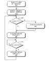
Fig. 2 shows the flow chart according to the operation of the video buffer management method of some embodiment.
Fig. 3 is the schematic diagram according to the computer system of some embodiment.
Embodiment
Fig. 1 is the schematic diagram according to the multi-tuner video system 100 of some embodiment.System 100 comprises the first tuner 110A that is connected to first interim (live) buffer 130A, the second tuner 110B, controller 120, file memory 140, switch 150 and the output port 152 that is connected to the second temporary buffer 130B.Display unit 160 can be connected to output port 152.Display unit can be embodied as (for example) TV, cathode ray tube, LCD (LCD) computer screen or any other appropriate display device.Will be with reference to multimedia personal computer system description system 100, this does not exist restricted with reference to just explanation for example.But, those skilled in the art will recognize that, can adopt the part of disclosed invention as the system of personal video recorder (PVR), TV, portable internet device or any other proper device or employing display unit.
Tuner 110A and 110B can be embodied as any suitable tuner, it can receive numeral or analog video and the audio-frequency information that is used for demonstration on display 160.At the first and second tuner 110A and 110B is among the embodiment of TV tuner, and they can comprise decoder 112A, 112B, with the conversion of the conversion of carrying out analog to digital, digital to analogy or carry out this two kinds of conversions.
From the angle of running the first tuner 11A is connected to the vision signal that receives input, for example the video information of importing from TV signal source with numeral or analog in form.If described input signal is a digital information, decoder 112A decompresses to described information and/or carries out format conversion in the case of necessary so.From the angle of running the first tuner 110A is connected to the input information of reception at first channel.With regard to the use in the literary composition, " channel " speech can comprise any suitable frequency or code, and perhaps any other is suitable is used to distinguish describe (delineation) of the channel that contains different video information.From the angle of running the second tuner 110B also is connected to receiving inputted signal, and it can be tuned to second channel.In certain embodiments, controller 120 can be provided with by the channel control data that inputs to controller 120 tuner 110A and 110B setting channel thereon.
Temporary buffer 130A is connected to tuner 110A, with the video that receives among the memory tuning device 110A, in order to the usefulness of controlled playback.Buffer 130A comprises memory module 132A, and it can store (for example) playback file.Similarly, temporary buffer 130B is connected to tuner 110B, with the video that receives among the memory tuning device 110B, in order to the usefulness of controlled playback.Buffer 130B comprises memory module 132B, and it can store (for example) playback file.
System 100 also comprises switch 150, and controller 120 is controlled it by control signal, thus will (for example) buffer 130A or the output of one of buffer 130B switch to output port 152.Output port 152 can be integrated in the switch 150, it is separated with switch 150.
Controller 120 comprises processor 122, memory module 124 and I/O (I/O) module 126.In certain embodiments, controller 120 can obtain quality settings information, and for example, the indication decoder should be captured the setting of the video with specified resolution.Controller 120 can be hardware, software or its appropriate combination that the various operations that literary composition describes are carried out in microprocessor, DSP, discrete logic, state machine or any other suitable being used for of (for example) one or more suitable programmings.
Fig. 2 shows the flow chart according to the operation of the video buffer management method of some embodiment.In certain embodiments, can implement operation shown in Figure 2 by controller 120.With reference to figure 2, in 210, controller receives the signal that is used for the first tuner 110A is tuned to first channel.For example, controller 120 can receive the signal from the user of system 100 by the user interface such as the interface on the display 160, perhaps receives the signal from remote control.By decoder 112A the vision signal that receives among the first tuner 110A is deciphered, and transmitted it to the memory module 132A of temporary buffer 130A.In 215, controller 120 first tuner 110A are set to be received in the video channel of discerning in the described signal.
The reception of controller 120 monitor log signals.If controller 120 receives tracer signal (operation 220), so selected vision signal is stored in (operation 225) in the file memory 140.For example, controller 120 can be stored in first vision signal in the playback file in the file memory 140.Afterwards, selected (promptly first) buffer 110A is connected to output port 152 (operation 230).For example, controller 120 can be connected to output port 152 with buffer 130A by indicator cock 150.In certain embodiments, display 160 can be connected to output port 152, thereby first vision signal is presented on the display 160.
Afterwards, controller 120 monitors that input changes the reception of signals, and this signal indicating controller switches to different (promptly second) storage buffer 130B with output port from selected (promptly first) storage buffer 130A.Change signal (operation 235) if controller 120 receives input, so the second buffer 110B is connected to output port 152 (operation 230).For example, controller 120 can be connected to output port 152 with buffer 130B by indicator cock 150, thereby second vision signal is presented on the display 160.
In certain embodiments, switch to the input of output port 152 not influence of buffer operation for system 100.Therefore, will switch to the second buffer 130B from the first buffer 130A to the input of output port 152 and neither can disturb from the first tuner 110A and carry vision signal, and also can not disturb the content of the first buffer 130A to the first buffer 130A.Therefore, the content of the first buffer 130A still can be used for playback operation, pausing operation etc.In addition, will switch to the second buffer 130B from the first buffer 130A to the input of output port 152 and can not disturb the recording operation of carrying out at first vision signal.
Can repetitive operation 220-240, thus the user can be switched at the interchannel of guiding display 160 into, and content that can storage buffer 130, described content is retained in the memory, in order to the usefulness of playback or pausing operation and record etc.
In certain embodiments, can be in computer system realization system 100.Fig. 3 is the schematic diagram of computer system 300, can make this system be suitable for the video buffer management of implementing to describe in the literary composition.Computer system 300 can comprise computer 308 and one or more subsidiary input/output device 306, for example, has display 302, keyboard 310 and the mouse 314 of screen 304.
Computer 308 has system hardware 320 and random access memory and/or the read-only memory 330 that comprises processor 322.From the angle of communication file memory 380 is connected to computer 308.File memory 380 can be inner, and for example, one or more hard disk drives perhaps can be outside, for example, and one or more external fixed disk drives, network attached storage device or independent storage networking.
In certain embodiments, system hardware 320 comprises motherboard 322 and at least one expansion board 370.Motherboard 322 contains a plurality of parts, comprises at least one processor 324, figure and storage control hub (GMCH) 326 and graphic process unit.Motherboard 322 also comprises the circuit trace (trace) that is used to receive the slot that is installed to the various parts on the motherboard 322 and is used for providing connection between described parts.
In certain embodiments, expansion board 370 can be I/O (I/O) plate.Expansion board 370 can comprise such as the I/O chipset of PCI-Express (PCIE) chipset 372, bus structures 374 and one or more I/O port 376.In certain embodiments, expansion board can comprise the parts that difference in functionality is provided.
Memory 330 comprises the operating system 340 of the operation that is used for supervisory computer 308.Operating system 340 is included as system hardware 320 and provides the hardware interface module 354 of interface, at least one is used for the file system 350 of the file that the operation of supervisory computer 308 adopts and the process control subsystem 352 of the process that management is carried out on computer 308.Operating system 340 also comprises system call interfaces module 342, and it provides interface between operating system 340 and one or more application of carrying out on the computer system.
In the middle of operation, the application program 362 invoke system call interface modules of on computer 308, carrying out 342, thus on the processor of computer, carry out one or more orders.System call interfaces module 342 is enabled the service of file system 350 and is managed the required file of described order, and the required process of described order is managed in the service of enabling process control subsystem 352.File system 350 and process control subsystem 352 will be enabled the service of hardware interface module 354 again, be connected with the interface of system hardware 320 with realization.
Therefore, example system and the method that is used for video buffer management described in the literary composition.The method of describing in the literary composition can be embodied as the logical order on the computer-readable medium.When carrying out described instruction on processor, described logical order makes the general-purpose computations device be programmed to implement the special purpose machinery of described method.Disposed by logical order, when carrying out the method for describing in the literary composition, described processor has constituted the structure that is used to carry out described method.
In addition, some embodiment can be provided as computer program, it can comprise machine readable or computer-readable medium, and described medium has being used for of being stored thereon to the instruction of computer (or other electronic installations) programming with the process carrying out literary composition and describe.Described computer-readable medium can include but not limited to the medium or the computer-readable medium that are suitable for store electrons instruction and/or data of floppy disk, hard disk, CD, CD-ROM, magneto optical disk, ROM, RAM, electronically erasable programmable rom (EPROM), electric EPROM (EEPROM), magnetic or optical card, flash memory or other suitable types.In addition, can with the storage discussed in the literary composition in the individual data storehouse, in a plurality of database, (for example, be stored in the form) otherwise can be stored in the option table (select forms).
In addition, some embodiment that discusses in the literary composition can be downloaded as computer program, wherein, can be (for example via communication link, modulator-demodulator or network connectivity), by the data-signal that comprises in carrier wave or other propagation mediums described program is transferred to requesting computer (for example, client computer) from remote computer (for example server).Correspondingly, here, should regard carrier wave as and comprise machine readable media.
Mentioned " embodiment " or " embodiment " is meant and comprised the described special characteristic of the described embodiment of contact, structure or characteristic at least in the middle of a certain enforcement in this specification.The phrase " in one embodiment " that appears at each position of this specification not necessarily refers to same embodiment all.
Claims (7)
1. a video system (100) comprising:
First tuner (110A);
First storage buffer (130A), it is connected to described first tuner (110A), to receive first vision signal from described first tuner (110A);
Second tuner (110B);
Second storage buffer (130B), it is connected to described second tuner (110B), to receive second vision signal from described second tuner (110B);
Controller, it comprises the logic that is used to carry out following operation:
To be directed to output port from described first vision signal of described first storage buffer (130A);
Reception is used for described output port is switched to from described first storage buffer (130A) signal of described second storage buffer (130B);
In response to described signal described output port is connected to described second storage buffer (130B), and does not disturb the operation of described first storage buffer (130A).
2. video system according to claim 1 also comprises the logic that is used to carry out following operation:
In described first tuner (110A), receive first vision signal; And
To described first vision signal decoding.
3. video system according to claim 1 also comprises the logic that is used to carry out following operation:
In described second tuner (110B), receive second vision signal; And
To described second vision signal decoding.
4. video system according to claim 1, also comprise be used for described first vision signal or described second vision signal one of them is stored in the logic in the file memory at least.
5. video system according to claim 1 also comprises the logic that is used to carry out following operation:
The reception signal of a part of the video signal content be stored in described first storage buffer (130A) that is used for resetting; And
In response to described signal described output port is connected to described first storage buffer (130A), and does not disturb the operation of described second storage buffer (130B).
6. video system according to claim 1 also comprises:
File memory; And
Be used for described first vision signal and described second vision signal one of them is stored in the logic of described file memory at least.
7. video system according to claim 1 also comprises the display that is connected to described output port.
Applications Claiming Priority (2)
| Application Number | Priority Date | Filing Date | Title |
|---|---|---|---|
| US11/710,825 US8049821B2 (en) | 2007-02-26 | 2007-02-26 | Video buffer management |
| US11/710825 | 2007-02-26 |
Publications (2)
| Publication Number | Publication Date |
|---|---|
| CN101257586A true CN101257586A (en) | 2008-09-03 |
| CN101257586B CN101257586B (en) | 2015-07-22 |
Family
ID=39715432
Family Applications (1)
| Application Number | Title | Priority Date | Filing Date |
|---|---|---|---|
| CN200810081090.6A Expired - Fee Related CN101257586B (en) | 2007-02-26 | 2008-02-26 | Video buffer management |
Country Status (3)
| Country | Link |
|---|---|
| US (1) | US8049821B2 (en) |
| CN (1) | CN101257586B (en) |
| TW (1) | TWI459816B (en) |
Cited By (1)
| Publication number | Priority date | Publication date | Assignee | Title |
|---|---|---|---|---|
| CN102769737A (en) * | 2012-07-19 | 2012-11-07 | 广东威创视讯科技股份有限公司 | Video image switching method and system |
Families Citing this family (8)
| Publication number | Priority date | Publication date | Assignee | Title |
|---|---|---|---|---|
| US8868023B2 (en) | 2008-01-04 | 2014-10-21 | 3D Radio Llc | Digital radio systems and methods |
| US8706023B2 (en) | 2008-01-04 | 2014-04-22 | 3D Radio Llc | Multi-tuner radio systems and methods |
| US8909128B2 (en) * | 2008-04-09 | 2014-12-09 | 3D Radio Llc | Radio device with virtually infinite simultaneous inputs |
| US8699995B2 (en) | 2008-04-09 | 2014-04-15 | 3D Radio Llc | Alternate user interfaces for multi tuner radio device |
| CA2742644C (en) | 2001-02-20 | 2016-04-12 | Caron S. Ellis | Multiple radio signal processing and storing method and apparatus |
| WO2009116972A1 (en) * | 2008-03-20 | 2009-09-24 | Thomson Licensing | System and method for processing priority transport stream data in real time in a multi-channel broadcast multimedia system |
| US10382815B2 (en) * | 2015-10-15 | 2019-08-13 | DISH Technologies L.L.C. | Apparatus, systems and methods for buffering of media content |
| CN107665679A (en) * | 2017-09-19 | 2018-02-06 | 惠科股份有限公司 | Liquid Crystal Display And Method For Driving |
Citations (2)
| Publication number | Priority date | Publication date | Assignee | Title |
|---|---|---|---|---|
| CN1691764A (en) * | 1999-11-30 | 2005-11-02 | 汤姆森特许公司 | Method for predicting succeeding channel selected by user |
| WO2007011356A1 (en) * | 2005-07-18 | 2007-01-25 | Thomson Licensing | System, method and apparatus for enabling channel surfing while buffering and recording of preferred channels |
Family Cites Families (7)
| Publication number | Priority date | Publication date | Assignee | Title |
|---|---|---|---|---|
| US5729300A (en) * | 1995-06-07 | 1998-03-17 | Samsung Electronics Co., Ltd. | Double-screen simultaneous viewing circuit of a wide-television |
| KR0165403B1 (en) * | 1995-06-09 | 1999-03-20 | 김광호 | Screen stop select apparatus and method in double wide tv |
| US6335728B1 (en) * | 1998-03-31 | 2002-01-01 | Pioneer Corporation | Display panel driving apparatus |
| US6115080A (en) * | 1998-06-05 | 2000-09-05 | Sarnoff Corporation | Channel selection methodology in an ATSC/NTSC television receiver |
| KR100590183B1 (en) * | 1999-06-25 | 2006-06-14 | 삼성전자주식회사 | Digital broadcasting receiver for implementing PIP using a plurality of decoders |
| FR2819671B1 (en) * | 2001-01-17 | 2003-05-16 | Thomson Licensing Sa | RECEIVING SYSTEM FOR MULTI-TUNER TELEVISION FOR AUTOMATICALLY CONNECTING EACH TUNER TO AT LEAST ONE ANTENNA, WHATEVER THE NUMBER OF ANTENNAS IT CONTAINS |
| US20050102700A1 (en) * | 2003-11-07 | 2005-05-12 | Cormack Christopher J. | Automatic program restoration when a programming break ends |
-
2007
- 2007-02-26 US US11/710,825 patent/US8049821B2/en active Active
-
2008
- 2008-01-28 TW TW097103072A patent/TWI459816B/en active
- 2008-02-26 CN CN200810081090.6A patent/CN101257586B/en not_active Expired - Fee Related
Patent Citations (2)
| Publication number | Priority date | Publication date | Assignee | Title |
|---|---|---|---|---|
| CN1691764A (en) * | 1999-11-30 | 2005-11-02 | 汤姆森特许公司 | Method for predicting succeeding channel selected by user |
| WO2007011356A1 (en) * | 2005-07-18 | 2007-01-25 | Thomson Licensing | System, method and apparatus for enabling channel surfing while buffering and recording of preferred channels |
Cited By (1)
| Publication number | Priority date | Publication date | Assignee | Title |
|---|---|---|---|---|
| CN102769737A (en) * | 2012-07-19 | 2012-11-07 | 广东威创视讯科技股份有限公司 | Video image switching method and system |
Also Published As
| Publication number | Publication date |
|---|---|
| US20080204604A1 (en) | 2008-08-28 |
| US8049821B2 (en) | 2011-11-01 |
| TW200840364A (en) | 2008-10-01 |
| CN101257586B (en) | 2015-07-22 |
| TWI459816B (en) | 2014-11-01 |
Similar Documents
| Publication | Publication Date | Title |
|---|---|---|
| CN101257586B (en) | Video buffer management | |
| US8327410B2 (en) | Networked-enabled mass storage dongle with networked media content aggregation | |
| US20190007230A1 (en) | Appliance and method for processing a plurality of high resolution multimedial operative functions and programs, which appliance is integrated with a television receiver screen, as well as remote control system and remote control device and method to set and display such multimedial operative functions and programs on to the screen of such an appliance | |
| EP2472856A2 (en) | Techniques for the association, customization and automation of content from multiple sources on a single display | |
| CN105472437A (en) | Video playing method and apparatus thereof | |
| EP1596581B1 (en) | A display device with data reading means | |
| CN102123257A (en) | Device control apparatus, device control method and program | |
| CN101923374A (en) | Non-standalone TV PC | |
| CN101364400B (en) | Information processing apparatus and output switching control method | |
| US6353800B1 (en) | Method, system, signal and software for sensing remote battery life based upon cursor characteristics | |
| CN102172038A (en) | Information processing device, display device, and information processing system | |
| CN213846839U (en) | Multimedia decoding device of digital broadcasting system and digital broadcasting system | |
| CN1976413B (en) | Digital data broadcasting receiver and method and device of controlling resolution of the same | |
| US20170150208A1 (en) | Audio and video playing device and method | |
| JP2012230627A (en) | Transmitter, receiver, and transmission method | |
| CN201893854U (en) | Audio-video delay system based on video channel card and universal server platform | |
| EP3035677B1 (en) | Image processing apparatus and control method thereof | |
| CN101482852B (en) | Computer system with multimedia interface apparatus | |
| CN204231576U (en) | Based on Slimport technology vehicle-mounted-mobile device interconnected systems | |
| CN204836437U (en) | On -vehicle application system | |
| CN201917342U (en) | Navigation all-in-one machine | |
| CN210627185U (en) | Signal transmission circuit and interactive intelligent panel | |
| CN100585660C (en) | Switching apparatus and data transfer method | |
| KR101179114B1 (en) | A device for controlling multimedia reproduction system | |
| CN206060977U (en) | A kind of new high resolution audio and video recorded broadcast box |
Legal Events
| Date | Code | Title | Description |
|---|---|---|---|
| C06 | Publication | ||
| PB01 | Publication | ||
| C10 | Entry into substantive examination | ||
| SE01 | Entry into force of request for substantive examination | ||
| C14 | Grant of patent or utility model | ||
| GR01 | Patent grant | ||
| CF01 | Termination of patent right due to non-payment of annual fee |
Granted publication date: 20150722 |
|
| CF01 | Termination of patent right due to non-payment of annual fee |