CN1012522B - Roller-track device for rotary hopper - Google Patents
Roller-track device for rotary hopperInfo
- Publication number
- CN1012522B CN1012522B CN88101375A CN88101375A CN1012522B CN 1012522 B CN1012522 B CN 1012522B CN 88101375 A CN88101375 A CN 88101375A CN 88101375 A CN88101375 A CN 88101375A CN 1012522 B CN1012522 B CN 1012522B
- Authority
- CN
- China
- Prior art keywords
- roller
- bearing
- axle
- hopper
- rollers
- Prior art date
- Legal status (The legal status is an assumption and is not a legal conclusion. Google has not performed a legal analysis and makes no representation as to the accuracy of the status listed.)
- Expired
Links
- 238000005096 rolling process Methods 0.000 claims abstract description 7
- 230000008093 supporting effect Effects 0.000 claims description 24
- 239000003351 stiffener Substances 0.000 claims description 9
- 230000000694 effects Effects 0.000 claims description 6
- NJPPVKZQTLUDBO-UHFFFAOYSA-N novaluron Chemical compound C1=C(Cl)C(OC(F)(F)C(OC(F)(F)F)F)=CC=C1NC(=O)NC(=O)C1=C(F)C=CC=C1F NJPPVKZQTLUDBO-UHFFFAOYSA-N 0.000 abstract description 3
- 230000002787 reinforcement Effects 0.000 abstract 1
- 238000009434 installation Methods 0.000 description 2
- 230000002159 abnormal effect Effects 0.000 description 1
- 230000003321 amplification Effects 0.000 description 1
- 230000006835 compression Effects 0.000 description 1
- 238000007906 compression Methods 0.000 description 1
- 230000008021 deposition Effects 0.000 description 1
- 238000007599 discharging Methods 0.000 description 1
- 238000012423 maintenance Methods 0.000 description 1
- 238000003199 nucleic acid amplification method Methods 0.000 description 1
- 230000000630 rising effect Effects 0.000 description 1
- 238000000926 separation method Methods 0.000 description 1
- 238000003466 welding Methods 0.000 description 1
Images

Classifications
-
- C—CHEMISTRY; METALLURGY
- C21—METALLURGY OF IRON
- C21B—MANUFACTURE OF IRON OR STEEL
- C21B7/00—Blast furnaces
- C21B7/18—Bell-and-hopper arrangements
- C21B7/20—Bell-and-hopper arrangements with appliances for distributing the burden
-
- F—MECHANICAL ENGINEERING; LIGHTING; HEATING; WEAPONS; BLASTING
- F27—FURNACES; KILNS; OVENS; RETORTS
- F27B—FURNACES, KILNS, OVENS, OR RETORTS IN GENERAL; OPEN SINTERING OR LIKE APPARATUS
- F27B1/00—Shaft or like vertical or substantially vertical furnaces
- F27B1/10—Details, accessories, or equipment peculiar to furnaces of these types
- F27B1/20—Arrangements of devices for charging
-
- F—MECHANICAL ENGINEERING; LIGHTING; HEATING; WEAPONS; BLASTING
- F27—FURNACES; KILNS; OVENS; RETORTS
- F27D—DETAILS OR ACCESSORIES OF FURNACES, KILNS, OVENS, OR RETORTS, IN SO FAR AS THEY ARE OF KINDS OCCURRING IN MORE THAN ONE KIND OF FURNACE
- F27D3/00—Charging; Discharging; Manipulation of charge
- F27D3/10—Charging directly from hoppers or shoots
-
- Y—GENERAL TAGGING OF NEW TECHNOLOGICAL DEVELOPMENTS; GENERAL TAGGING OF CROSS-SECTIONAL TECHNOLOGIES SPANNING OVER SEVERAL SECTIONS OF THE IPC; TECHNICAL SUBJECTS COVERED BY FORMER USPC CROSS-REFERENCE ART COLLECTIONS [XRACs] AND DIGESTS
- Y10—TECHNICAL SUBJECTS COVERED BY FORMER USPC
- Y10S—TECHNICAL SUBJECTS COVERED BY FORMER USPC CROSS-REFERENCE ART COLLECTIONS [XRACs] AND DIGESTS
- Y10S209/00—Classifying, separating, and assorting solids
- Y10S209/91—Feed hopper
Landscapes
- Engineering & Computer Science (AREA)
- Mechanical Engineering (AREA)
- General Engineering & Computer Science (AREA)
- Chemical & Material Sciences (AREA)
- Manufacturing & Machinery (AREA)
- Materials Engineering (AREA)
- Metallurgy (AREA)
- Organic Chemistry (AREA)
- Filling Or Emptying Of Bunkers, Hoppers, And Tanks (AREA)
- Rollers For Roller Conveyors For Transfer (AREA)
Abstract
The rolling track comprises a series of rollers which are supported by a fixed reinforcement and on which travels the circular pedestal of the hopper. This circular pedestal is equipped with a toothed ring in order to be driven in rotary movement about its vertical axis. The rollers are grouped in pairs, and each pair of rollers is carried by an axle pivotable about a radial axis; with each of the rollers being carried in its axle by floating bearings mounted on springs.
Description
The present invention relates to be used for the roller track device of the revolving hopper of blast furnace charging apparatus, be made up of a series of roller, these rollers are supported by the fixed stiffener, and the round bearing of hopper moves on roller, have ring gear on the bearing, rotate around Z-axis so that drive bearing.
The present invention particularly is directed to shaft furnace, the standby hopper of the centre charging device of blast furnace especially, but be not limited in this.Minimum for the size separation phenomenon is dropped to, the someone proposes at charging, suitable words rotary hopper during discharging recently.The simplest terms of settlement comprises: a series of track rollers are installed on the circular stiffener of supporting hopper, under the driving gear effect that the ring gear with the hopper bearing meshes hopper are rotated on track roller.Make these supporting track rollers excessive for fear of weight (full load is the hundreds of ton) owing to hopper, the roller of some amount will be installed at least, for example eight, at first glance, as if should support evenly distributed these rollers on the whole circumference of stiffener in circle.
Find now that if like this, hopper is not evenly to be supported by all rollers, and often be by wherein three support.This non-homogeneous supporting can be by the deposition of dirt on the wearing and tearing of the unbalancedness of charging weight, some rollers or distortion, the roller surface of revolution, and institutes such as the incorrect vertical adjustment of roller cause.So not only cause the stable bad of hopper, and all rollers must be designed to wherein three and can support whole load, to avoid too early wearing and tearing, except the extra-expense that this oversized dimensions is brought, roller also needs quite big and wide.But contradict with the experience of this respect so again.Rule of thumb, the supporting track roller must not approach as far as possible guarantee to have and frictionally rotate and prevent wheel because the slight deformation of bearer frame and only go up carrying on one point for example.
The purpose of this invention is to provide a kind of new roller track device of aforementioned type, wherein all rollers support hopper fifty-fifty.
When reaching this order, roller track device provided by the present invention is characterised in that, in one embodiment, roller is by to grouping, every pair roller by one can around longitudinal axis rotate spool supported, each roller can be supported by the floating bearing that is installed on the spring.
Select among the embodiment an advantage, the roller track device comprises eight rollers, that is to say that four pair rollers are supported by four axles that are installed on the circuit orbit lubber's point.
Because two rollers can be supported around the axle of horizontal rotational shaft by same, roller is located automatically so that bear equal weight substantially.Yet hopper may be only keeps balance by two pair rollers of relative position on the diameter afterwards, and and can't help in addition that the roller of relative position supports on two pairs of diameters.For avoiding this possibility, all rollers are equipped with the floating bearing that is contained on the spring in it, and the size of these springs is such, when using eight rollers, each spring can bear 1/8th of the overall loading that will support when not compressing, in case load is excessive, spring is compressed.In other words, suppose only to be kept under the equilibrated state by four rolling at hopper, the spring that supports these rollers does not bear load, and they are compressed, and hopper is reduced a little, so that all rollers are evenly supported.So just be enough to that all rollers are had and only support overall loading and add the size of 1/8th weight behind certain safe per-cent.
Every axle is preferably supported by radially being installed in the axle that is fixed to the supporting member internal surface on the circular supporting stiffener.Every axle comprises two boxes that are welded on the central axle sleeve both sides, and axle sleeve removably is contained on its supporting spindle.
According to another characteristic of the invention, every box thereon, lower surface has a rectangular aperture that roller is passed through, there are two relative rectangular apertures on inside and outside surface, in each opening bearing is housed, each bearing that is installed in opposite side is in the vertical edges place of rectangular aperture band perpendicular grooves, so that keep the position of bearings also can vertically slide, and each bearing freely is placed on the whisker that is supported by cartridge bottom.
Each roller preferably is installed on the axle by rolling bearing, and these both sides are supported by floating bearing.
Hopper is by being installed in the horizontal roller maintenance level on each supporting member.
According to another characteristic of the invention, each supporting member has the rocking bar of a radial position, and there is a head that is positioned on the circular supporting base of hopper its inner, its relative the other end is subjected to the brute spring effect, in normal operation, make head that one slight distance be arranged on bearing, but do not contact.Under the abnormal work situation, earthquake for example takes place, these rocking bars make hopper remain on the appropriate location.
Characteristics that other is detailed and feature will be by drawing to the detailed description of preferred embodiment that provides down and with reference to accompanying drawing, wherein:
The side-view of the hopper that Fig. 1 is supported for roller track device according to the present invention;
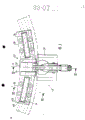
Fig. 2 is the orthographic plan of roller track device;
Fig. 3 is the amplification view of a pair of roller in its bolster;
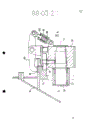
Fig. 4 is the part sectioned view along IV among Fig. 3-the IV plane is vertically cut open;
Fig. 5 represents along a pair roller of radially looking of hopper axis and the outside drawing of its supporting member;
Fig. 6 represents the longitudinal sectional view by the roller in the VI-VI of Fig. 3 middle section.
Fig. 1 represents the standby hopper 10 of blast furnace charging apparatus, and hopper design becomes can rotate around its longitudinal center line O.Hopper 10 is supported by the roller track device of being made up of four rolling group 14,16 18 and 20 (referring to Fig. 2) by circular stiffener 12.These roller set, every group comprises a pair roller, is installed in four lubber's point places on the circular stiffener 12.
Fig. 3 represents one of roller set seen in Figure 2, exactly is the enlarged view of roller set 18.Because other roller set 14,16 is identical with roller set 18 with 20, below only describe that one of them has been enough.
As shown in Figure 3, roller set 18 mainly comprises the axle 22 of supporting one pair roller 24,26.The axle 22 be installed in the welding or by on the supporting member 28 that is bolted on the stiffener 12.One of characteristics of axle 22 this installations are exactly that axle can wind the horizontal axis X rotation of radially extending with respect to hopper, that is to say that the axle 22 and the vertical rotating shaft line of hopper intersect.
Fig. 4 represents the cross section that supporting member 28 is vertically cut open by axis X, has represented the installation detail drawing of axle 22.Its axis of cylindrical mandrel 30-is fixed on the supporting member 28 for rotation X-.Axle 22 has an axle sleeve 32, and its big I is slided it and can be around axle 30 rotations on axle 30.Axle sleeve 32 remains on the appropriate location by the header board 34 that is spun on the axle 30.
Axle 22 also comprises two boxes 36,38 that are welded on central axle sleeve 32 both sides symmetrically.These two boxes 36,38 have formed the container of roller 24,26, and will be described in detail with reference to Fig. 5 and 6 below.Yet owing to the container of two rollers 24 and 26 is no difference, thereby the container of following pair roller 24 is described in detail.
As shown in Figure 6, the cross section that holds the box 36 of roller 24 is roughly rectangle, by upper wall 40, and lower wall 42, inwall 44 and outer wall 46 are formed, and all these walls are welded to each other together.Upper and lower wall 40,42 has a width to be slightly larger than the elongated rectangular opening 46,45 of roller 24 thicks, so that roller can pass through.
Have at sidewall 44 and 46 places and to be roughly orthogonal opening 50,52() referring to Fig. 5.In these openings 50,52, also have rectangular plate 54,56, form the pedestal bearing of roller 24.These plates 54,56 have a wider portion to form footing 58,60 along the base.The width of plate 54,56 is slightly larger than opening 52, and in side-walls perpendicular grooves 62,64 is arranged, and its cross section is the U type, wherein embeds the vertical side edge of each opening 50,52.Because plate 54 and 56 supported by the sidewall 44,46 of box 36, they can slide with respect to sidewall by perpendicular grooves 62,64.As illustrated in Figures 5 and 6, every block of plate 54,56 is placed on a pair of volution compression spring 66,68 by its footing 58,60, and spring is supported by the inwall 42 of box 36.
As can be seen from Figure 6, roller 24 is supported by the rolling bearing on the axle 72 70, axle 72 plate 54 and 56 supportings by the roller both sides.
Every roller 24 is installed with ralocatable mode like this, and its position is on the one hand by hopper weight applied force, determined by four spring applied forces of these bearings of supporting on the other hand.
Shown in Figure 6, the cross section of all rollers is a frustum, and its potential awl point is positioned on the rotation O point of hopper.The slideway of bearing 74 tilts, so that equate to meet with the tapering of roller.This tapering is that the friction for the zone that prevents to contact between roller and bearing 74 rolling surfaces is provided with.
On each supporting member 28 horizontal roller 78 is housed also, this roller is walking on bearing 74 equally during the hopper rotation, and supports hopper from the side.
One rocking bar 80 is arranged on each support 28, and this bar is rotatably installed on the cantilever 82 of supporting member 28 and is positioned in the radial position of hopper 10.The outer end of bar 80 is hinged with supporting member 28 by a cylinder body 84.Cylinder body 84 inside are one to act on the powerful whisker on the piston 82, and cylinder body links to each other with bar 80 by piston.The other end of bar 80 has a head 88, and this head keeps a slight distance with bearing 74 under the effect of spring 86, so that when the normal work period hopper rotates, makes head 88 and bearing 74 keep disengaging.Especially, this device is safe and simple for being installed in the geographic stove of earthquake risk, and can prevent that hopper from overturning suddenly, for example because the vibration of lifting machine.In fact, bar 80 can prevent the swing of hopper 10 under the high vibration effect by the effect of spring 86, and spring 86 has weakened the possible vibration of bearing 74, and can prevent the stroke of the rising of bearing greater than piston 82 in the cylinder body 84.
Claims (9)
1, the roller track that is used for the revolving hopper of blast furnace charging apparatus, comprise a series of rollers, these rollers support by the supporting member (28) that is installed on the fixed stiffener (12), the round bearing (74) of hopper (10) moves on roller, this bearing has ring gear (76), rotate so that be driven around its longitudinal center line O, it is characterized in that: roller is pressed grouping
Every pair roller (24,26) is supported by the axle (22) around longitudinal axis (X) rotation,
Every pair roller is supported by the floating bearing (54,56) that is installed on the spring in the axle (22).
2, roller track according to claim 1 is characterized in that: roller track comprises by four eight rollers that axle supported that are positioned on the circuit orbit on four lubber's points.
3, roller track according to claim 1 is characterized in that: every axle (22) is supported by the axle (30) on the internal surface that radially is installed in the supporting member (28) that is fixed on the garden shape stiffener (12).
4, according to any one described roller track in the claim 1 to 3, it is characterized in that: each axle (22) comprises two boxes (36,38) that are welded on central axle sleeve (32) both sides, and this axle sleeve removably is contained on the bolster (30).
5, roller track according to claim 4 is characterized in that:
The upper and lower surface of every box (40,42) has elongated rectangular aperture (4848 '), so that roller (24) is passed through, the inside and outside surface of box (44,46) has two relative rectangular apertures (50,52), bearing (54,56) is housed in each opening, the opposite side of each bearing has the perpendicular grooves (62,64) that cooperates with the vertical edges of rectangular aperture (50,52), also can vertically slide with the holding position;
Each bearing (54,56) freely is placed on the whisker (66,68) that is supported by box (36) bottom.
6, roller track according to claim 5 is characterized in that: each roller (24) by rolling bearing (70) be installed in both sides by floating bearing (54,56) supported the axle (72) on.
7, according to any one described roller track in the claim 1 to 6, it is characterized in that: the horizontal roller (78) that supports hopper (10) from the side is housed on each supporting member (28).
8, according to any one described roller track in the claim 1 to 7, it is characterized in that: a rocking bar (80) radially is installed on each supporting member (28), there is a head (88) that is positioned at hopper round bearing (74) top its inner, and its relative the other end is made head (88) remain on the effect of the brute spring (80) at bearing (74) last one little spacing place.
9, according to any one described roller track in the claim 1 to 8, it is characterized in that:
The cross section of all rollers is a frustum, and its potential awl point is positioned on the rotation (0) of hopper.
The obliquity of the slideway of bearing (74) conforms to the tapering of roller.
Applications Claiming Priority (2)
| Application Number | Priority Date | Filing Date | Title |
|---|---|---|---|
| LU86824A LU86824A1 (en) | 1987-03-24 | 1987-03-24 | RUNWAY FOR A ROTATING HOPPER |
| LU86824 | 1987-03-24 |
Publications (2)
| Publication Number | Publication Date |
|---|---|
| CN88101375A CN88101375A (en) | 1988-10-05 |
| CN1012522B true CN1012522B (en) | 1991-05-01 |
Family
ID=19730897
Family Applications (1)
| Application Number | Title | Priority Date | Filing Date |
|---|---|---|---|
| CN88101375A Expired CN1012522B (en) | 1987-03-24 | 1988-03-23 | Roller-track device for rotary hopper |
Country Status (12)
| Country | Link |
|---|---|
| US (1) | US4812100A (en) |
| JP (1) | JP2584274B2 (en) |
| KR (1) | KR960005725B1 (en) |
| CN (1) | CN1012522B (en) |
| AU (1) | AU592928B2 (en) |
| CS (1) | CS269998B2 (en) |
| DE (1) | DE3809535C2 (en) |
| FR (1) | FR2613053B1 (en) |
| GB (1) | GB2205132B (en) |
| IT (1) | IT1216027B (en) |
| LU (1) | LU86824A1 (en) |
| NL (1) | NL8800723A (en) |
Families Citing this family (7)
| Publication number | Priority date | Publication date | Assignee | Title |
|---|---|---|---|---|
| LU86823A1 (en) * | 1987-03-24 | 1988-11-17 | Wurth Paul Sa | CONTROL DEVICE FOR HYDRAULIC CYLINDERS MOUNTED ON A ROTATING HOPPER |
| BE1003055A4 (en) * | 1989-03-30 | 1991-11-05 | Amc N V | APPARATUS FOR THE SAME SPREAD OF COVERING MATERIAL. |
| LU88495A1 (en) * | 1994-06-14 | 1996-02-01 | Wurth Paul Sa | Suspension device for a rotating body |
| US5833092A (en) * | 1997-02-20 | 1998-11-10 | Summit Machine Builders, Corp. | Apparatus for feeding poorly flowable dry particulate materials |
| CA2653370C (en) * | 2009-02-10 | 2014-12-16 | Alvin Herman | Rotatable bin or like object |
| US9266662B1 (en) * | 2012-09-11 | 2016-02-23 | Vm Fiber Feeders Inc. | Bulk fiber dispenser |
| CN104249556A (en) * | 2013-06-27 | 2014-12-31 | 田珉 | 3D product printer and program-controlled path |
Family Cites Families (5)
| Publication number | Priority date | Publication date | Assignee | Title |
|---|---|---|---|---|
| FR967871A (en) * | 1947-06-20 | 1950-11-14 | Arthur G Mac Kee And Co | Improvements to rotary distributors for blast furnaces, or relating to these devices |
| FR1091259A (en) * | 1954-01-09 | 1955-04-08 | Dingler Ets | Rotary closing device for furnaces and in particular blast furnaces |
| US2901132A (en) * | 1958-03-14 | 1959-08-25 | Interlake Iron Corp | Blast furnace seal |
| US4029220A (en) * | 1975-11-28 | 1977-06-14 | Greaves Melvin J | Distributor means for charging particulate material into receptacles |
| JPS61128087A (en) * | 1984-11-27 | 1986-06-16 | 川崎重工業株式会社 | Dual load supporter for rotary kiln |
-
1987
- 1987-03-24 LU LU86824A patent/LU86824A1/en unknown
-
1988
- 1988-03-01 AU AU12526/88A patent/AU592928B2/en not_active Ceased
- 1988-03-09 IT IT8819696A patent/IT1216027B/en active
- 1988-03-16 US US07/168,901 patent/US4812100A/en not_active Expired - Fee Related
- 1988-03-18 FR FR8803504A patent/FR2613053B1/en not_active Expired
- 1988-03-21 GB GB8806662A patent/GB2205132B/en not_active Expired - Lifetime
- 1988-03-22 DE DE3809535A patent/DE3809535C2/en not_active Expired - Fee Related
- 1988-03-23 CN CN88101375A patent/CN1012522B/en not_active Expired
- 1988-03-23 KR KR1019880003142A patent/KR960005725B1/en not_active IP Right Cessation
- 1988-03-23 JP JP63070836A patent/JP2584274B2/en not_active Expired - Lifetime
- 1988-03-23 NL NL8800723A patent/NL8800723A/en not_active Application Discontinuation
- 1988-03-24 CS CS881943A patent/CS269998B2/en unknown
Also Published As
| Publication number | Publication date |
|---|---|
| IT8819696A0 (en) | 1988-03-09 |
| CS194388A2 (en) | 1989-09-12 |
| JP2584274B2 (en) | 1997-02-26 |
| AU592928B2 (en) | 1990-01-25 |
| CS269998B2 (en) | 1990-05-14 |
| LU86824A1 (en) | 1988-11-17 |
| KR880011559A (en) | 1988-10-29 |
| FR2613053B1 (en) | 1989-11-24 |
| DE3809535A1 (en) | 1988-10-06 |
| GB2205132B (en) | 1990-11-21 |
| AU1252688A (en) | 1988-09-22 |
| JPS63258786A (en) | 1988-10-26 |
| IT1216027B (en) | 1990-02-22 |
| DE3809535C2 (en) | 1996-12-12 |
| GB8806662D0 (en) | 1988-04-20 |
| GB2205132A (en) | 1988-11-30 |
| US4812100A (en) | 1989-03-14 |
| KR960005725B1 (en) | 1996-05-01 |
| CN88101375A (en) | 1988-10-05 |
| NL8800723A (en) | 1988-10-17 |
| FR2613053A1 (en) | 1988-09-30 |
Similar Documents
| Publication | Publication Date | Title |
|---|---|---|
| US5934029A (en) | Base isolator having mutually eccentric rotators | |
| CN1012522B (en) | Roller-track device for rotary hopper | |
| MXPA03008464A (en) | Idler roller for transport conveyor. | |
| US7597281B2 (en) | Roller mill having a modular construction | |
| CA2280609C (en) | Cone crusher for rock | |
| CN1106762A (en) | Cantilevered bucket-wheel stocker-unloader bucket-wheel unloader and stocker for stockyard | |
| CN1903440A (en) | Up rocking type roller mill | |
| EP0402545B1 (en) | Crushing machine | |
| CN203147199U (en) | Large rotary table stable bearing and driving system | |
| CN212943509U (en) | FWZ type bag-turning type centrifugal machine | |
| CN2214401Y (en) | Contilever bucket-wheel stocker and feeder | |
| CN112390024A (en) | Linkage type tray loading mechanism | |
| CN1051260C (en) | An arrangement for fastening a roll-unit firmly to a roll stand | |
| US4932536A (en) | Magazine for calender rolls | |
| CN201020444Y (en) | Plane round vibrating screen | |
| CN212598035U (en) | Cantilever support device | |
| US4279140A (en) | Mill roll balance system | |
| AU635674B2 (en) | A method of operating a mill and a mill operated in accordance with the method | |
| CA2276830A1 (en) | Mill | |
| US5003833A (en) | Gyrating drive for particle screening machine | |
| CN208932825U (en) | A kind of overhead traveling crane of handling steel construction | |
| US590322A (en) | Spindle-bearing | |
| CN2356764Y (en) | Roll set device for rolling mill | |
| US4222704A (en) | Roller support for a lift pump | |
| SU1121021A1 (en) | Apparatus for suspension thickening |
Legal Events
| Date | Code | Title | Description |
|---|---|---|---|
| C06 | Publication | ||
| PB01 | Publication | ||
| C10 | Entry into substantive examination | ||
| SE01 | Entry into force of request for substantive examination | ||
| C13 | Decision | ||
| GR02 | Examined patent application | ||
| C14 | Grant of patent or utility model | ||
| GR01 | Patent grant | ||
| C15 | Extension of patent right duration from 15 to 20 years for appl. with date before 31.12.1992 and still valid on 11.12.2001 (patent law change 1993) | ||
| OR01 | Other related matters | ||
| C19 | Lapse of patent right due to non-payment of the annual fee | ||
| CF01 | Termination of patent right due to non-payment of annual fee |