CN1012400B - Error correcting method and circuit - Google Patents
Error correcting method and circuitInfo
- Publication number
- CN1012400B CN1012400B CN89106740A CN89106740A CN1012400B CN 1012400 B CN1012400 B CN 1012400B CN 89106740 A CN89106740 A CN 89106740A CN 89106740 A CN89106740 A CN 89106740A CN 1012400 B CN1012400 B CN 1012400B
- Authority
- CN
- China
- Prior art keywords
- code
- circuit
- cyclic redundancy
- mentioned
- sign indicating
- Prior art date
- Legal status (The legal status is an assumption and is not a legal conclusion. Google has not performed a legal analysis and makes no representation as to the accuracy of the status listed.)
- Expired
Links
Images
Classifications
-
- G—PHYSICS
- G03—PHOTOGRAPHY; CINEMATOGRAPHY; ANALOGOUS TECHNIQUES USING WAVES OTHER THAN OPTICAL WAVES; ELECTROGRAPHY; HOLOGRAPHY
- G03G—ELECTROGRAPHY; ELECTROPHOTOGRAPHY; MAGNETOGRAPHY
- G03G15/00—Apparatus for electrographic processes using a charge pattern
-
- H—ELECTRICITY
- H03—ELECTRONIC CIRCUITRY
- H03M—CODING; DECODING; CODE CONVERSION IN GENERAL
- H03M13/00—Coding, decoding or code conversion, for error detection or error correction; Coding theory basic assumptions; Coding bounds; Error probability evaluation methods; Channel models; Simulation or testing of codes
- H03M13/03—Error detection or forward error correction by redundancy in data representation, i.e. code words containing more digits than the source words
- H03M13/05—Error detection or forward error correction by redundancy in data representation, i.e. code words containing more digits than the source words using block codes, i.e. a predetermined number of check bits joined to a predetermined number of information bits
- H03M13/09—Error detection only, e.g. using cyclic redundancy check [CRC] codes or single parity bit
-
- G—PHYSICS
- G06—COMPUTING; CALCULATING OR COUNTING
- G06F—ELECTRIC DIGITAL DATA PROCESSING
- G06F11/00—Error detection; Error correction; Monitoring
- G06F11/07—Responding to the occurrence of a fault, e.g. fault tolerance
- G06F11/08—Error detection or correction by redundancy in data representation, e.g. by using checking codes
- G06F11/10—Adding special bits or symbols to the coded information, e.g. parity check, casting out 9's or 11's
-
- H—ELECTRICITY
- H03—ELECTRONIC CIRCUITRY
- H03M—CODING; DECODING; CODE CONVERSION IN GENERAL
- H03M13/00—Coding, decoding or code conversion, for error detection or error correction; Coding theory basic assumptions; Coding bounds; Error probability evaluation methods; Channel models; Simulation or testing of codes
- H03M13/03—Error detection or forward error correction by redundancy in data representation, i.e. code words containing more digits than the source words
- H03M13/05—Error detection or forward error correction by redundancy in data representation, i.e. code words containing more digits than the source words using block codes, i.e. a predetermined number of check bits joined to a predetermined number of information bits
- H03M13/13—Linear codes
- H03M13/15—Cyclic codes, i.e. cyclic shifts of codewords produce other codewords, e.g. codes defined by a generator polynomial, Bose-Chaudhuri-Hocquenghem [BCH] codes
-
- H—ELECTRICITY
- H03—ELECTRONIC CIRCUITRY
- H03M—CODING; DECODING; CODE CONVERSION IN GENERAL
- H03M13/00—Coding, decoding or code conversion, for error detection or error correction; Coding theory basic assumptions; Coding bounds; Error probability evaluation methods; Channel models; Simulation or testing of codes
- H03M13/29—Coding, decoding or code conversion, for error detection or error correction; Coding theory basic assumptions; Coding bounds; Error probability evaluation methods; Channel models; Simulation or testing of codes combining two or more codes or code structures, e.g. product codes, generalised product codes, concatenated codes, inner and outer codes
Abstract
Reed-Solomon outer code for error correction concatenated with a CRC inner code for detection of miscorrections. The error correction circuit has a parallel circuit of an RS coding sequence circuit and a CRC coding sequence circuit to form a sequence circuit and a control circuit for selecting either one of them depending on the desired operation mode. High speed decoding is obtained since the CRC computation is carried out in parallel with the Reed-Solomon decoding operation.
Description
The present invention relates to the circuit that the error-detecting of error recovery by Reed Solomon code and Cyclic Redundancy Code is proofreaied and correct the error in data of record body, particularly can make Cyclic Redundancy Code calculate the Error-Correcting Circuit of high speed.
In general, in numeral record speech disk, numeral record speech tape, photomagneto disk etc.,, information m bit is handled as 1 symbol for the correction data mistake, and 2 seven symbols of redundant symbol are had seven symbols is the recoverable sign indicating number, can adopt the Reed Solomon code of m=8.
Wherein, photomagneto disk adopts the Reed Solomon code of 8 bigger symbol correction of calibration capability, and other pen recorders adopt the Reed Solomon code of 2~3 symbol correction.In order to proofread and correct the mistake of 8 symbols at high speed, for example (be stated from " about the research of the Reed Solomon code decoding method that utilizes the Galois arithmetic unit " as long as constitute the Galois Field computing circuit, Jitian he, the 9th bends information theory and uses procceedings, the 167th~170 page (1986), the computing that repeats Euclidean algorithm or Ba Lun-Kan Bu algorithm etc. is just passable.
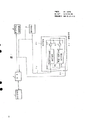
For example, Fig. 3 is that the block scheme of Error-Correcting Circuit in the past (is stated from " research that photomagneto disk is used error correcting device ", Jitian he, clear 61 letters are total complete big, 6-53(1987) paper), shown in the figure, for corresponding to long especially code length, formation in parallel is carried out the sequential circuit of the syndrome computation of Reed Solomon code by collection of letters data, and utilizes same circuit to obtain errors present.
Among the figure, (1) is memory buffer, comprises staggered a plurality of DSs of Reed Solomon code (external code) and Cyclic Redundancy Code (internal code) in order to storage.
(2) for untiing the interface of the data interlace in the memory buffer (1).(3) be the Galois Field computing circuit, it carries out arithmetic according to the syndrome of each Reed Solomon code on Galois Field, obtains the data in wrong numerical value (pattern) and the correction buffer storer (1) simultaneously.(4) be sequential circuit, the syndrome computation that it carries out Reed Solomon code by each data is simultaneously by arithmetic concurrent operation chaining search as a result.These circuit couple together by data bus.
(5) be the control circuit of control interface (2), Galois Field computing circuit (3) and sequential circuit (4), in control circuit (5), the Cyclic Redundancy Code of circuit wafer coding sequential circuit (narration later on) couples together with sequential circuit (4) in addition.
In DS, be internal code with the Cyclic Redundancy Code and be that the structure of external code has the following advantages with Reed Solomon code that promptly error detection capability is higher, even disappear correction in Reed Solomon code, mistake school probability is also less.In addition, the staggered utilization by these codes also has stronger structure to error burst.And Cyclic Redundancy Code is to be a kind of reflected code of purpose with the error-detecting, can be used in the error-detecting but Reed Solomon code is the same with Cyclic Redundancy Code.
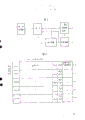
But, in 5.25 inches Worm type photomagneto disk, also adopt Reed Solomon code as standard (for example, ISO/TC97/SC23 sees view ISO, the 1st ISO DP9171/4, July, 1987), Fig. 4 illustrates the standard format example of 512 bytes/section.
Here used Reed Solomon code, its original polynomial expression P(X) represent with following formula:
P(X)=X
8+X
5+X
3+X
2+1……(1)
Its generator polynomial G(X) represent with following formula:

In the formula, a
i=(β
i)
88, β is original polynomial expression P(X) unit.In addition, about Cyclic Redundancy Code, its original polynomial expression and P(X) identical, its generator polynomial g(X) represent with following formula:

In the form of Fig. 4, the Reed Solomon code checking symbol that usefulness is proofreaied and correct in Reed Solomon code is set at last at each Reed Solomon code information symbol of #0~#4.
Secondly, the generation action to the cyclic redundancy check character of Cyclic Redundancy Code coding sequential circuit number describes.
At first, obtain the I that represents with following formula (4) by data

In the formula, L is staggered number, and n is a code length, and d is the minor increment of Reed Solomon code, i
j, K is an information symbol, if i 〉=L-4, then i
j, O=0.
In 512 bytes/section, L=5, n=122, d=17, and obtaining corresponding to I(X) cyclic redundancy check character number.Here, corresponding to I(X) C(X) as follows:
C(X)=I(X)X
4+R
e〔I(X)X
4/
(X)〕
=I(X)
4+a
3X
3+a
2X
2+a
1X+a
0……(5)
In the formula, R
e[A/B] is the residual polynomial of A/B, a
K(K=0~3) are cyclic redundancy check character number.
If obtain I(X), the checking symbol a of (5) formula then
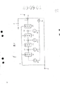
KCan be configured by simple circuit.Fig. 5 is the pie graph of this Cyclic Redundancy Code of expression coding sequential circuit, and (6) are I(X among the figure) input end, (7) are cyclic redundancy check character a
0~a
4Output terminal, (8) signal input end for being connected with control circuit (5), (9)~(12) be the eight bit register of series connection, (13)~(16) be the logic add circuit that the output end in each register (9)~(12) inserts, (17)~(20) are a in the distolateral connection of input of each register (9)~(12)
MThe multiplier of (according to (3) formula, M=40,117,228,97) times usefulness, (21) are the gate circuit of the logic of the output of logic add circuit (16) and control signal being imported each mlultiplying circuit (17)~(20).
The action of circuit describes when secondly, the Cyclic Redundancy Code of Fig. 5 being encoded.
Add reset signal by signal input end (8) to register (9)~(12), to eliminate the content of each register.If begin to import I(X from high order by input end (6)), I(X then) symbol carry out logical add by the logic add circuit (16) and the output of register (12), and by gate circuit (21) input mlultiplying circuit (17)~(20).Therefore, form a by mlultiplying circuit (17)
40Data doubly are latched in the register (9) according to the timing signal by signal input end (8) input, and, form a by mlultiplying circuit (18)
117Data are doubly carried out logical add by the logical add circuit (13) and the output of register (9), and its addition result is latched in the register (10) according to the timing signal by control signal input (8) input.The output data of following mlultiplying circuit (19) and (20) is carried out same processing.
So, data I (X) when all importing, is latched a of (5) formula respectively in register (9), register (10), register (11) and register (12)
0Data, a
1Data, a
2Data and a
3Data.Secondly, after gate circuit (21) disconnection, these data are moved in register (9)~(12) in order, and as cyclic redundancy check character a
0~a
3Export by output terminal.
Corresponding to each checking symbol write area of form shown in Figure 4, under the situation of coding, with these cyclic redundancy check characters a
0~a
3Write as follows:
a
3→i
1,0
a
2→i
2,0
a
1→i
3,0
a
0→i
4,0
In addition, under the situation of decoding, unanimity and carry out error-detecting more whether.
For collection of letters word (data that comprise mistake) #0~#4, the decoding action is proofreaied and correct Reed Solomon code in turn by following program 1 ,~4.
1, obtain the syndrome of Reed Solomon code by collection of letters word.
2, obtain error location polynomial and wrong numerical value polynomial expression by syndrome.
3, obtain errors present by error location polynomial by chaining search.
4, by errors present, error location polynomial and wrong numerical value polynomial expression are obtained wrong numerical value and are proofreaied and correct.
In above program, 2 and 4,, 1 and 3, share execution by Galois Field computing circuit (3), sequential circuit (4) respectively.
The data of having proofreaied and correct like this, can deposit in the memory buffer (1).And, after whole coded words (coded data) are proofreaied and correct with Reed Solomon code, utilize the Cyclic Redundancy Code coding sequential circuit of Fig. 5 to obtain cyclic redundancy check character number, carry out the calculating of Cyclic Redundancy Code again by logical add.
As mentioned above, Error-Correcting Circuit in the past is if obtain I(X), then can easily obtain cyclic redundancy check character a
KBut must carry out logical add to staggered information symbol, and at I(X) 0 time in the cyclic redundancy check character part must be calculated as 0, in addition, also there is following problem, promptly when decoding, if not after staggered whole coded words are proofreaied and correct with Reed Solomon code, then can not begin the calculating of Cyclic Redundancy Code.
The present invention can address the above problem, and its purpose is not obtained I(X) and the Error-Correcting Circuit of calculating cyclic redundancy code check symbol at high speed.
Error-Correcting Circuit involved in the present invention constitutes sequential circuit with Reed Solomon code sequential circuit and Cyclic Redundancy Code coding sequential circuit as parallel circuit, and selects a certain side's operational pattern by control circuit.
In the present invention, utilize the characteristics of Cyclic Redundancy Code for linear code, parallel with the computing action of the Galois Field computing circuit that carries out Reed Solomon code decoding, utilize Cyclic Redundancy Code coding sequential circuit, the cyclic redundancy check character of the coded word message part of proofreading and correct with Reed Solomon code before obtaining number, and utilize the Galois Field computing circuit, the cyclic redundancy check character of this and former resulting coded word number is carried out logical add one by one.
Then, utilize the Galois Field computing circuit to obtain cyclic redundancy check character number (the cyclic redundancy check character data that write down corresponding to Reed Solomon code information portion branch are generated), this and former resulting cyclic redundancy check character number are carried out logical add, and the cyclic redundancy check character that the information symbol part of the resulting cyclic redundancy check character of this logical add number and Reed Solomon code is disposed number compares, thereby can detect mistake.
Fig. 1 is the block scheme of one embodiment of the invention, and (1)~(3) and (5) are circuit same as described above among the figure.
(4A) for constituting the sequential circuit of pith of the present invention, by constituting identical Cyclic Redundancy Code coding sequential circuit (22) with Fig. 5 and carrying out the parallel circuit formation of the Reed Solomon code sequential circuit of Reed Solomon code syndrome computation and chaining search.At each output end of Cyclic Redundancy Code coding sequential circuit (22), Reed Solomon code sequential circuit (23), insert bus output control gate (26), (27).(24) be by the control signal of control circuit (5) to sequential circuit (4A) input, (25) are for connecting the data bus of sequential circuit (4A) and interface (2) and Galois Field computing circuit (3) usefulness.
Fig. 6 is a kind of structure of control circuit among Fig. 1 (5), wherein (28) are microprocessor, (29) be response microcomputer signal, produce control chart 1 each circuit (2), (3), the control of control signal (4A) (24) produces circuit, (30)~(33) be the signal wire of control sequential circuit of the present invention (4A), (30) be the reseting controling signal of sequential circuit (4A), (31) be the permission control effecting signal of sequential circuit (4A), (32) be the displacement output control signal of sequential circuit (4A), (33) are the controlled or identification control signals that Reed Solomon code sequential circuit (23) is controlled of identification Cyclic Redundancy Code coding sequential circuit (22).(34)~(39) be gate circuit, (40) be negative circuit, (41) be the reseting controling signal of Cyclic Redundancy Code coding sequential circuit, (42) be Cyclic Redundancy Code sequential circuit permission control effecting signal, (43) be the displacement output control signal of Cyclic Redundancy Code coding sequential circuit, (44) be the reset signal of Reed Solomon code sequential circuit, (45) be the permission control effecting signal of Reed Solomon code sequential circuit, (46) are the displacement output control signals of Reed Solomon code sequential circuit.Here, control signal (41)~(46) are with " 1 " expression operation control, and identification control signal (33) output " 1 " when Cyclic Redundancy Code coding sequential circuit is controlled, output " 0 " when the Reed Solomon code sequential circuit is controlled.
At first, before explanation operation of the present invention, earlier meaning and the operation that wherein will use " model selection " once illustrated.
In sequential circuit (4A), what Cyclic Redundancy Code coding sequential circuit (22) and Reed Solomon code sequential circuit (23) carried out is same operation, promptly in the sequential circuit in the resetting of register, sequential circuit work, the sequential circuit data of register export in proper order.
In the present invention, because Cyclic Redundancy Code coding sequential circuit (22) and Reed Solomon code sequential circuit (23) are not to operate simultaneously, so control signal wire can abbreviation.
Fig. 6 embodiment that comes to this.Reseting controling signal (30), permission control effecting signal (31), displacement output control signal (32) are controlled Cyclic Redundancy Code coding sequential circuit (22), Reed Solomon code sequential circuit (23) jointly.Control on earth wherein which circuit is decided by identification control signal (33), gate circuit (34)~(39) and negative circuit (40).For example, when identification control signal (33) is " 1 ", each control signal wire (41)~(43) of Cyclic Redundancy Code coding sequential circuit are because gate circuit (34)~(36) are that " opening " is so there are control signal (30)~(32) of control generation circuit (29) to pass through.And on the other hand, each control signal (44)~(46) of Reed Solomon code sequential circuit, because gate circuit (37)~(39) become " pass " attitude through negative circuit (40), control signal (30)~(32) that produce circuit (29) with control are irrelevant, be generally " 0 ", so do not carry out each control operation.But when identification control signal (33) is " 0 ", just carry out and above-mentioned anti-phase operation.
As mentioned above, Cyclic Redundancy Code sequential circuit (22) and Reed Solomon code sequential circuit (23), that side no matter, when needing only side operation, owing to be provided with identification control signal (33), can carry out " model selection " of Cyclic Redundancy Code coding circuit (22) operator scheme and Reed Solomon code sequential circuit (23) operator scheme.Certainly, each control signal (41)~(46) that control signal generation circuit (29) also can rely on microcomputer (28) directly to produce sequential circuit, owing at this moment also do not operate simultaneously, so be to have carried out " model selection " naturally.
Secondly, with reference to the process flow diagram of Fig. 2, the action of one embodiment of the invention shown in Figure 1 is described.And, be that example describes with the photomagneto disk that utilizes Fig. 4 standard format here.
In Fig. 2, S01, S11, S21, S31 and S41 are equivalent to above-mentioned program 1,, S02, S12, S22, S32 and S42 are equivalent to program 2,, S03, S13, S23, S33 and S43 are equivalent to program 3, and S04, S14, S24, S34 and S44 are equivalent to program 4; And S05, S15, S25, S35 and S45 are the Cyclic Redundancy Code calculation procedure, S06, S16, S26, S36 and S46 are the cyclic redundancy check character storing step, S50 is the logical add step, and S60 is a comparison step, the repeating step S32~S43 of not shown centre.
And, in sequential circuit (4A), carry out model selection according to control signal (24) at first, so that Reed Solomon code sequential circuit (23) work.
Reed Solomon code sequential circuit (23), finish by step S01~S04 after the correction of collection of letters word # 0, obtain the Reed Solomon code syndrome (S11) of collection of letters word # 1, and send in the Galois Field computing circuit (3) by bus output control gate (27).
Galois Field computing circuit (3) is obtained error location polynomial and the wrong numerical value polynomial expression (S12) of collection of letters # 1 by the syndrome data, and is proceeded correction work.
During this period, in sequential circuit (4A), carry out model selection, so that Cyclic Redundancy Code coding sequential circuit (22) work according to control signal (24).The information data of calibrated collection of letters word # 0 is according to information symbol i shown in Figure 4
0, n-d, i
0N-d-1 ..., i
0,0Order, encode in the sequential circuit (22) by interface (2) and data bus (25) input Cyclic Redundancy Code by memory buffer (1).Cyclic Redundancy Code coding sequential circuit (22) is obtained the cyclic redundancy check character a of collection of letters word # 0 as mentioned above
K(S05).At this moment, replace I(X) 1 collection of letters digital data of input.
When step S05 and S12 end, the cyclic redundancy check character data of collection of letters word # 0, send in the Galois Field computing circuit (3) by bus output control gate (26) and data bus (25) by Cyclic Redundancy Code coding sequential circuit (22), and store (S06) obtain the cyclic redundancy check character data of collection of letters word # 1 by later step S15 after.
Secondly, sequential circuit (4A) carries out model selection according to control signal (24), so that Reed Solomon code sequential circuit (23) work, and, obtain the errors present (S13) of collection of letters word # 1 by the chaining search computing according to the polynomial data that Galois Field computing circuit (3) is exported.
Then, when obtaining the errors present of collection of letters word # 1, obtain wrong numerical value, and proofread and correct collection of letters word #1(S14) by Galois Field computing circuit (3).
Below same, by step S01~S46, all the collection of letters word # 0~#4 in Fig. 4 form section are handled operation.
At this moment, the cyclic redundancy check character number (a on the form (i1,0~i4,0)
3~a
0) also as information data input 3, but temporarily former state ground is placed.
In addition, by the later cyclic redundancy check character data of the resulting collection of letters word of step S15, S25, S35 and S45 # 1, by step S16, S26, S36 and S46, carry out logical add in turn with the cyclic redundancy check character data of collection of letters word # 0, and deposit in the Galois Field computing circuit (3).
At last, the cyclic redundancy check character of writing information symbol data part number is carried out logical add with Galois Field computing circuit (3), obtain its result as the cyclic redundancy check character of information data number, again the data after the cyclic redundancy check character data logical add of it and collection of letters word # 0~4 are carried out logical add (S50).
Then, whether the CRC sign indicating number that is write on the form in resulting CRC code data and the memory buffer (1) consistent comparing (S60), thereby can detect the mistake after being proofreaied and correct by Reed Solomon code.
In addition, in the above-described embodiments, the operation of the Cyclic Redundancy Code of obtaining when decoding is illustrated, but self-evident, the situation of the cyclic redundancy check character when obtaining coding number is suitable for too.
As mentioned above, according to the present invention, sequential circuit is made of the parallel circuit of Reed Solomon code sequential circuit and Cyclic Redundancy Code coding sequential circuit, a certain side carries out work according to operational pattern, as long as the additional cycles redundanat code is calculated required Min. circuit, do not require I(X) just can detect mistake by Cyclic Redundancy Code, and, because with the decoding of Reed Solomon code and the computing of execution Cyclic Redundancy Code, so can obtain to carry out with high speed the Error-Correcting Circuit of section single-bit correction.
Being simply described as follows of accompanying drawing:
Fig. 1 is the block scheme of expression one embodiment of the invention, Fig. 2 is the process flow diagram of key diagram 1 work, Fig. 3 represents the block scheme of Error-Correcting Circuit in the past, Fig. 4 is the key diagram of the 512 bytes/sector data standard format of expression photomagneto disk, Fig. 5 represents the pie graph of general Cyclic Redundancy Code coding sequential circuit, and Fig. 6 is the structural drawing of Fig. 1 control circuit embodiment.
(1) ... memory buffer, (2) ... interface,
(3) ... the Galois Field computing circuit, (4A) ... sequential circuit,
(5) ... control circuit, (22) ... cyclic redundancy
During the sign indicating number coding
The preface circuit,
(23) ... the Read-Solomon sequential circuit,
(24) ... control signal.
In addition, prosign is represented identical or considerable part among the figure.
Claims (5)
1, a kind of Error-Correcting Circuit has following circuit:
The memory buffer of storage DS, this DS are external code with Reed one Solomon code with the correction data mistake and are constituting serial a plurality of interlocking of internal code with the Cyclic Redundancy Code that detects above-mentioned error in data;
Untie the interface of the staggered usefulness of above-mentioned DS;
Proofread and correct the Galois Field computing circuit of usefulness, this computing circuit carries out arithmetic on the Jia Luomen territory by the syndrome of above-mentioned Reed one Solomon code, obtains wrong numerical value by errors present simultaneously;
Reed one Solomon code sequential circuit, this sequential circuit are by the above-mentioned syndrome of above-mentioned data computation, and the result by above-mentioned arithmetic obtains errors present by chaining search simultaneously;
Carry out the Cyclic Redundancy Code coding sequential circuit of the coding calculating of above-mentioned Cyclic Redundancy Code;
Control the control circuit of above-mentioned interface, above-mentioned Galois Field computing circuit, above-mentioned Reed one Solomon code sequential circuit and above-mentioned Cyclic Redundancy Code coding sequential circuit,
It is characterized in that:
Sequential circuit is that the parallel circuit by above-mentioned Reed one Solomon code sequential circuit and above-mentioned Cyclic Redundancy Code coding sequential circuit constitutes, simultaneously.
Control signal according to above-mentioned control circuit output, when above-mentioned Reed one Solomon code sequential circuit is worked, above-mentioned Cyclic Redundancy Code coding sequential circuit is not worked, and when above-mentioned Cyclic Redundancy Code coding sequential circuit was worked, above-mentioned Reed one Solomon code sequential circuit was not worked.
2, a kind of method of error recovery is suitable for having the Error-Correcting Circuit of following circuit:
The buffer storage of storage DS, this DS are external code with the Reed Solomon code with the correction data mistake and are constituting serial a plurality of interlocking of internal code with the Cyclic Redundancy Code that detects above-mentioned error in data;
Untie the interface of the staggered usefulness of above-mentioned DS;
Proofread and correct the Galois Field computing circuit of usefulness, this computing circuit carries out arithmetic on the Jia Luomen territory by the syndrome of above-mentioned Reed Solomon code, obtains wrong numerical value by errors present simultaneously;
Reed Solomon code sequential circuit, this sequential circuit are by the above-mentioned syndrome of above-mentioned data computation, and the result by above-mentioned arithmetic obtains errors present by chaining search simultaneously;
Carry out the Cyclic Redundancy Code coding sequential circuit of the coding calculating of above-mentioned Cyclic Redundancy Code;
Control the control circuit of above-mentioned interface, above-mentioned Galois Field computing circuit, above-mentioned Reed Solomon code sequential circuit and above-mentioned Cyclic Redundancy Code coding sequential circuit;
It is characterized in that:
In each staggered code train, utilize Cyclic Redundancy Code coding sequential circuit to obtain the CRC sign indicating number of the 1st code train, and it is stored in the Galois Field computing circuit; Secondly, utilize Cyclic Redundancy Code coding sequential circuit to obtain the CRC sign indicating number of the 2nd code train, and the CRC sign indicating number of the 1st code train stored in it and the Galois Field computing circuit carried out storing after the logical add, identical with the 2nd code train to the staggered section of its an execution part, with obtain at last be stored in CRC sign indicating number in the Galois Field computing circuit time CRC sign indicating number part in the write buffering memory in, when decoding according to memory buffer in the CRC sign indicating number consistent mistake that detects whether.
3, the error correcting method of putting down in writing according to claim 2, it is characterized in that: when coding, before calculating cyclic redundancy code check sign indicating number, remove after the CRC sign indicating number part in the memory buffer, when calculating cyclic redundancy code check sign indicating number, utilize Cyclic Redundancy Code coding sequential circuit to come calculating cyclic redundancy code check sign indicating number (comprising the CRC sign indicating number part in the memory buffer).
4, the error correcting method of putting down in writing according to claim 2, be characterized in: when decoding, for the 1st code train, utilize Read-Solomon to decipher the data of the 1st code train in the correction buffer storer, for the 2nd code train, during carrying out Read-Solomon decoding, when not using the Read-Solomon sequential circuit, select Cyclic Redundancy Code coding sequential circuit to calculate the CRC sign indicating number of the 1st code train, identical later on, during the Read-Solomon decoding of carrying out each code train, utilized the CRC sign indicating number of the code train that Read-Solomon decoding proofreaies and correct before calculating, and according to whether consistent with the CRC sign indicating number in the memory buffer mistake that detects after the Read-Solomon decoding of the logical add result of the CRC sign indicating number of each code train.
5, the error correcting method of putting down in writing according to claim 2, it is characterized in that: when decoding, when calculating the CRC sign indicating number of each code train, utilize Cyclic Redundancy Code coding sequential circuit to come calculating cyclic redundancy code check sign indicating number when (comprising the CRC sign indicating number part in the memory buffer), utilizing Cyclic Redundancy Code coding sequential circuit to come calculating cyclic redundancy code check sign indicating number (comprising the CRC sign indicating number part in the memory buffer).Utilize the Galois Field computing circuit to calculate the CRC sign indicating number of the cyclic redundancy check (CRC) code part in the memory buffer, utilize the Galois Field computing circuit that logical add is carried out in it and former CRC sign indicating number, from before the CRC sign indicating number remove after the influence of the check code in the memory buffer, according to whether with the consistent mistake that detects of the CRC sign indicating number in the memory buffer.
Applications Claiming Priority (2)
| Application Number | Priority Date | Filing Date | Title |
|---|---|---|---|
| JP218262/88 | 1988-09-02 | ||
| JP63218262A JP2695195B2 (en) | 1988-09-02 | 1988-09-02 | Error correction circuit |
Publications (2)
| Publication Number | Publication Date |
|---|---|
| CN1040698A CN1040698A (en) | 1990-03-21 |
| CN1012400B true CN1012400B (en) | 1991-04-17 |
Family
ID=16717116
Family Applications (1)
| Application Number | Title | Priority Date | Filing Date |
|---|---|---|---|
| CN89106740A Expired CN1012400B (en) | 1988-09-02 | 1989-09-01 | Error correcting method and circuit |
Country Status (7)
| Country | Link |
|---|---|
| US (1) | US5068857A (en) |
| EP (1) | EP0357461B1 (en) |
| JP (1) | JP2695195B2 (en) |
| KR (1) | KR930001071B1 (en) |
| CN (1) | CN1012400B (en) |
| CA (1) | CA1322056C (en) |
| DE (1) | DE68924944T2 (en) |
Cited By (1)
| Publication number | Priority date | Publication date | Assignee | Title |
|---|---|---|---|---|
| CN100461664C (en) * | 2005-07-15 | 2009-02-11 | 联发科技股份有限公司 | Error-correcting apparatus including multiple error-correcting modules functioning in parallel and related method |
Families Citing this family (41)
| Publication number | Priority date | Publication date | Assignee | Title |
|---|---|---|---|---|
| EP0318364A1 (en) * | 1987-11-24 | 1989-05-31 | Gaston Huguenin | Safe-unit |
| JPH0458619A (en) * | 1990-06-28 | 1992-02-25 | Canon Inc | Error correction system |
| WO1992013344A1 (en) * | 1991-01-22 | 1992-08-06 | Fujitsu Limited | Error correction processing device and error correction method |
| EP0523969B1 (en) * | 1991-07-18 | 1997-12-29 | Canon Kabushiki Kaisha | Error correction encoding and decoding system |
| DE69325415T2 (en) * | 1992-05-18 | 1999-11-25 | Canon Kk | Data processing device |
| US5446745A (en) * | 1992-10-05 | 1995-08-29 | Mitsubishi Semiconductor America, Inc. | Apparatus for correcting errors in optical disks |
| JP2821324B2 (en) * | 1992-11-04 | 1998-11-05 | 三菱電機株式会社 | Error correction circuit |
| US5357527A (en) * | 1992-12-31 | 1994-10-18 | Trimble Navigation Limited | Validation of RAM-resident software programs |
| CA2113941A1 (en) * | 1993-01-25 | 1994-07-26 | Andrew J. Macdonald | Error correcting decoder and decoding method for receivers in digital cellular communications systems |
| US5465260A (en) * | 1993-11-04 | 1995-11-07 | Cirrus Logic, Inc. | Dual purpose cyclic redundancy check |
| KR0147150B1 (en) * | 1995-06-29 | 1998-09-15 | 김주용 | Crc error debugging system using decoder |
| JP3154679B2 (en) * | 1996-10-18 | 2001-04-09 | 三菱電機株式会社 | Error correction decoding apparatus and decoding method for concatenated code |
| US5970075A (en) * | 1997-06-18 | 1999-10-19 | Uniden San Diego Research And Development Center Inc. | Method and apparatus for generating an error location polynomial table |
| CN100383886C (en) * | 1998-02-25 | 2008-04-23 | 松下电器产业株式会社 | Error corrector and its method |
| US6092231A (en) * | 1998-06-12 | 2000-07-18 | Qlogic Corporation | Circuit and method for rapid checking of error correction codes using cyclic redundancy check |
| KR100340125B1 (en) * | 1999-10-06 | 2002-06-10 | 지 천 만 | Power supply circuit for ultraviolet sterilizer |
| US7111228B1 (en) | 2002-05-07 | 2006-09-19 | Marvell International Ltd. | System and method for performing parity checks in disk storage system |
| US7007114B1 (en) | 2003-01-31 | 2006-02-28 | Qlogic Corporation | System and method for padding data blocks and/or removing padding from data blocks in storage controllers |
| US7287102B1 (en) | 2003-01-31 | 2007-10-23 | Marvell International Ltd. | System and method for concatenating data |
| US7492545B1 (en) | 2003-03-10 | 2009-02-17 | Marvell International Ltd. | Method and system for automatic time base adjustment for disk drive servo controllers |
| US7064915B1 (en) | 2003-03-10 | 2006-06-20 | Marvell International Ltd. | Method and system for collecting servo field data from programmable devices in embedded disk controllers |
| US7457903B2 (en) | 2003-03-10 | 2008-11-25 | Marvell International Ltd. | Interrupt controller for processing fast and regular interrupts |
| US7039771B1 (en) | 2003-03-10 | 2006-05-02 | Marvell International Ltd. | Method and system for supporting multiple external serial port devices using a serial port controller in embedded disk controllers |
| US7870346B2 (en) | 2003-03-10 | 2011-01-11 | Marvell International Ltd. | Servo controller interface module for embedded disk controllers |
| US7526691B1 (en) | 2003-10-15 | 2009-04-28 | Marvell International Ltd. | System and method for using TAP controllers |
| KR100594241B1 (en) * | 2004-01-29 | 2006-06-30 | 삼성전자주식회사 | RS decoder circuit having forward Chien search type |
| US7139150B2 (en) | 2004-02-10 | 2006-11-21 | Marvell International Ltd. | Method and system for head position control in embedded disk drive controllers |
| US7120084B2 (en) | 2004-06-14 | 2006-10-10 | Marvell International Ltd. | Integrated memory controller |
| US8166217B2 (en) | 2004-06-28 | 2012-04-24 | Marvell International Ltd. | System and method for reading and writing data using storage controllers |
| US7757009B2 (en) | 2004-07-19 | 2010-07-13 | Marvell International Ltd. | Storage controllers with dynamic WWN storage modules and methods for managing data and connections between a host and a storage device |
| US8032674B2 (en) | 2004-07-19 | 2011-10-04 | Marvell International Ltd. | System and method for controlling buffer memory overflow and underflow conditions in storage controllers |
| US9201599B2 (en) | 2004-07-19 | 2015-12-01 | Marvell International Ltd. | System and method for transmitting data in storage controllers |
| US7386661B2 (en) | 2004-10-13 | 2008-06-10 | Marvell International Ltd. | Power save module for storage controllers |
| US7240267B2 (en) | 2004-11-08 | 2007-07-03 | Marvell International Ltd. | System and method for conducting BIST operations |
| US7802026B2 (en) | 2004-11-15 | 2010-09-21 | Marvell International Ltd. | Method and system for processing frames in storage controllers |
| US7290189B2 (en) * | 2005-03-28 | 2007-10-30 | Verigy (Singapore) Pte. Ltd. | Compilation of calibration information for plural testflows |
| US7609468B2 (en) | 2005-04-06 | 2009-10-27 | Marvell International Ltd. | Method and system for read gate timing control for storage controllers |
| CN100437805C (en) * | 2006-01-16 | 2008-11-26 | 华中科技大学 | Error correction code and data format for high density optical disk |
| WO2014041596A1 (en) * | 2012-09-11 | 2014-03-20 | 三菱電機株式会社 | Safety controller |
| CN107196665B (en) * | 2017-06-14 | 2020-11-06 | 中国电子科技集团公司第三十六研究所 | Identification method of error correction erasure correcting RS code |
| US11061772B2 (en) * | 2018-12-14 | 2021-07-13 | Samsung Electronics Co., Ltd. | FPGA acceleration system for MSR codes |
Family Cites Families (8)
| Publication number | Priority date | Publication date | Assignee | Title |
|---|---|---|---|---|
| US4162480A (en) * | 1977-01-28 | 1979-07-24 | Cyclotomics, Inc. | Galois field computer |
| EP0096163B1 (en) * | 1982-06-15 | 1988-06-01 | Kabushiki Kaisha Toshiba | Apparatus for dividing the elements of a galois field |
| DE3575646D1 (en) * | 1984-03-24 | 1990-03-01 | Philips Nv | METHOD FOR TRANSMITTING INFORMATION WITH ERROR CORRECTION FOR DATA WORDS, AN ERROR CORRECTION DECODING METHOD FOR SUCH DATA WORDS, AN ARRANGEMENT FOR INFORMATION TRANSFER FOR USE WITH THE METHOD, AND A METHOD FOR USING AN APPARATUS. |
| JPH07114371B2 (en) * | 1986-01-10 | 1995-12-06 | ソニー株式会社 | Decryption device |
| CA1264091A (en) * | 1986-01-10 | 1989-12-27 | Yoichiro Sako | Generator for error correcting code and decoder for the code |
| JP2605271B2 (en) * | 1987-02-10 | 1997-04-30 | ソニー株式会社 | Error correction and checking device |
| US4949342A (en) * | 1987-04-14 | 1990-08-14 | Matsushita Electric Industrial Co., Ltd. | Code error detecting method |
| JPS63257966A (en) * | 1987-04-15 | 1988-10-25 | Matsushita Electric Ind Co Ltd | Method for detecting code error |
-
1988
- 1988-09-02 JP JP63218262A patent/JP2695195B2/en not_active Expired - Fee Related
-
1989
- 1989-08-31 KR KR1019890012461A patent/KR930001071B1/en not_active IP Right Cessation
- 1989-09-01 DE DE68924944T patent/DE68924944T2/en not_active Expired - Fee Related
- 1989-09-01 US US07/401,968 patent/US5068857A/en not_active Expired - Lifetime
- 1989-09-01 EP EP89308902A patent/EP0357461B1/en not_active Expired - Lifetime
- 1989-09-01 CN CN89106740A patent/CN1012400B/en not_active Expired
- 1989-09-05 CA CA000610262A patent/CA1322056C/en not_active Expired - Fee Related
Cited By (1)
| Publication number | Priority date | Publication date | Assignee | Title |
|---|---|---|---|---|
| CN100461664C (en) * | 2005-07-15 | 2009-02-11 | 联发科技股份有限公司 | Error-correcting apparatus including multiple error-correcting modules functioning in parallel and related method |
Also Published As
| Publication number | Publication date |
|---|---|
| KR900005242A (en) | 1990-04-13 |
| DE68924944D1 (en) | 1996-01-11 |
| EP0357461A2 (en) | 1990-03-07 |
| JPH0267825A (en) | 1990-03-07 |
| DE68924944T2 (en) | 1996-08-08 |
| CA1322056C (en) | 1993-09-07 |
| CN1040698A (en) | 1990-03-21 |
| US5068857A (en) | 1991-11-26 |
| EP0357461B1 (en) | 1995-11-29 |
| JP2695195B2 (en) | 1997-12-24 |
| KR930001071B1 (en) | 1993-02-15 |
| EP0357461A3 (en) | 1991-11-13 |
Similar Documents
| Publication | Publication Date | Title |
|---|---|---|
| CN1012400B (en) | Error correcting method and circuit | |
| KR101135425B1 (en) | Method and device for multi phase error-correction | |
| US8239725B2 (en) | Data storage with an outer block code and a stream-based inner code | |
| JP3165099B2 (en) | Error correction method and system | |
| CN101868831B (en) | Memory controller supporting rate compatible punctured codes | |
| JP5723967B2 (en) | Method, encoder apparatus, and solid-state storage device for recording input data to s-level storage of a solid-state storage device | |
| CN100386735C (en) | Method and system for restoring data in storage device using a combined error correction and detection approach | |
| US7188295B2 (en) | Method and apparatus for embedding an additional layer of error correction into an error correcting code | |
| JP2520551B2 (en) | Decoder capability enhancement method for decoding interleaved error correction code | |
| WO2008021045A2 (en) | System and method for correcting errors in non-volatile memory using product codes | |
| WO1985002958A1 (en) | Method and apparatus for decoding error correction code | |
| WO1999038170A1 (en) | Encoding method and memory device | |
| CN1881477A (en) | Error detection and correction for encoded data | |
| JP2013524609A5 (en) | ||
| JPH11283396A (en) | Memory device | |
| CN1140965C (en) | Vanish Correction method and vanish correction circuit | |
| CN101281788A (en) | Flash memory system as well as control method thereof | |
| WO2011150152A1 (en) | Outer code protection for solid state memory devices | |
| US20100017682A1 (en) | Error correction code striping | |
| JP2002509331A5 (en) | ||
| JP4099844B2 (en) | Memory device | |
| US8819331B2 (en) | Memory system and memory controller | |
| CN1311640C (en) | Error-correcting method and device used in decoding interleaved PS code | |
| US6615384B1 (en) | Encoding/decoding method and apparatus and disk storage device | |
| JP2021033530A (en) | Memory system |
Legal Events
| Date | Code | Title | Description |
|---|---|---|---|
| C10 | Entry into substantive examination | ||
| SE01 | Entry into force of request for substantive examination | ||
| C06 | Publication | ||
| PB01 | Publication | ||
| C13 | Decision | ||
| GR02 | Examined patent application | ||
| C14 | Grant of patent or utility model | ||
| GR01 | Patent grant | ||
| C15 | Extension of patent right duration from 15 to 20 years for appl. with date before 31.12.1992 and still valid on 11.12.2001 (patent law change 1993) | ||
| OR01 | Other related matters | ||
| C19 | Lapse of patent right due to non-payment of the annual fee | ||
| CF01 | Termination of patent right due to non-payment of annual fee |