CN101207964B - Electricity removal apparatus - Google Patents
Electricity removal apparatus Download PDFInfo
- Publication number
- CN101207964B CN101207964B CN2007103022178A CN200710302217A CN101207964B CN 101207964 B CN101207964 B CN 101207964B CN 2007103022178 A CN2007103022178 A CN 2007103022178A CN 200710302217 A CN200710302217 A CN 200710302217A CN 101207964 B CN101207964 B CN 101207964B
- Authority
- CN
- China
- Prior art keywords
- electricity
- electrode
- voltage
- removal apparatus
- state
- Prior art date
- Legal status (The legal status is an assumption and is not a legal conclusion. Google has not performed a legal analysis and makes no representation as to the accuracy of the status listed.)
- Expired - Fee Related
Links
Images


Classifications
-
- H—ELECTRICITY
- H05—ELECTRIC TECHNIQUES NOT OTHERWISE PROVIDED FOR
- H05F—STATIC ELECTRICITY; NATURALLY-OCCURRING ELECTRICITY
- H05F3/00—Carrying-off electrostatic charges
- H05F3/04—Carrying-off electrostatic charges by means of spark gaps or other discharge devices
Abstract
The present invention relates to suppressing wear and contamination of the electrode needle as well as effectively removing the electricity from a charged body. An electricity removal mode in which the electrode needle is applied with a high voltage to produce ions and a halt mode in which the electrode needle is halted are provided, that are alternatively selected based on a selection of a user. The halt mode includes a halt period during which the high voltage is not basically applied on the electrode needle. When a self discharge occurs by approach of a charged body in this halt period and an absolute value of current that flows through the resistance exceeds the first threshold value, the electricity removal operation is initiated in which the high voltage is applied on the electrode needle to produce ions. Subsequently, after a predetermined time period passes, for example, the electricity removal operation is terminated and the halt period is resumed.
Description
Technical field
The present invention relates to a kind of electricity removal apparatus, its be used to eliminate the main body of being charged by positive charge or negative electrical charge with.
Background technology
Known a kind of through produce cation or anion eliminate charged main body with the electricity removal apparatus (open No.2000-58290 of japanese unexamined patent and the open No.2003-86393 of japanese unexamined patent) of electricity.This electricity removal apparatus produces ion through on electrode needle, loading high voltage to form corona discharge, so this electricity removal apparatus can have such problem, promptly ion produces ability because the wearing and tearing of electrode needle and corrosion and degenerate in time.
In order to address the above problem; The open No.2003-86393 of japanese unexamined patent discloses a kind of technology based on electricity removal apparatus; This electricity removal apparatus is used for alternately being carried in through the high voltage that will have opposed polarity and alternately produces cation and anion on the public electrode pin; And before negative voltage loads after positive voltage loads be provided the time period that does not have voltage to load; For example, thus also make ionic equilibrium before this arrives time period, become neutrality rapidly to the voltage adjustment that will be loaded into electrode needle.According to invention the disclosing of 2003-86393, through a time period between the voltage that has opposed polarity between loading is provided, reduced the running time length of electrode needle, therefore suppress the wearing and tearing and the corrosion of electrode needle and suitably kept ionic equilibrium.
Summary of the invention
Target of the present invention provide can eliminate effectively charged main body with electricity the time suppress the wearing and tearing of electrode needle and the electricity removal apparatus of corrosion.
According to the present invention, above-mentioned technical problem can solve through a kind of electricity removal apparatus is provided, and said electricity removal apparatus can produce ion through on electrode needle, loading high voltage, and said electricity removal apparatus comprises: the electrode that is used for producing ion; Be connected to the electrode voltage circuit, be used for producing positive voltage and negative voltage power supply and come electric energy to be provided for said electrode; The self discharge testing circuit, said self discharge testing circuit does not detect the self discharge of said electrode needle when loading high voltage on the said electrode needle; And control unit, be used to control the positive voltage and the negative voltage that produce by said potential circuit, make it be in said electrode and initiatively do not produce in first state of ion and second state that said electrode initiatively produces ion.Wherein when said self discharge testing circuit when said electrode needle detects the self discharge of said electrode needle in by the interval of operation suspension (halt); Be used for high voltage is carried on the said electrode needle and eliminate operation with the electricity that produces ion and be activated; Wherein said pause period is included in the park mode, and when said charged main body with electricity after being eliminated said electricity eliminate that operation is terminated and said pause period is restarted.
According to the present invention, when electrode needle during by operation suspension, the appearance of charged main body makes and has induced the opposite polarity electric charge with said charged main body at the tip of said electrode needle, and this makes self discharge produce easily.In addition, through being utilized in the generation that the said self discharge testing circuit of arranging in the said device detects said self discharge, not only can detecting the appearance of charged main body but also can start said electricity and eliminate operation.So, can utilize said electricity removal apparatus self automatically to detect the appearance of charged main body and utilize said electricity removal apparatus to eliminate electricity, and need not to rely on external sensor.So electrode needle normally is in SBR and can be loaded high voltage, therefore suppressed wearing and tearing and the corrosion of said electrode needle and eliminated effectively said charged main body with.
Said self discharge testing circuit can be to be used for being arranged in flowing through the circuit that the value of the electric current of the resistance between said electrode needle and the high voltage generation circuit detects, or is used for being arranged in flowing through the circuit that the value of the electric current of the resistance between said electrode needle and the ground detects.Absolute value according to the electric current of the said resistance of flowing through not only can detect self discharge, and can learn the effect that electricity is eliminated because when charged main body with flow through when the reducing value (absolute value) of electric current of said resistance of electric charge sum also diminished.Therefore; Think when surpassing first threshold and detect self discharge through value (absolute value) at the electric current of the said resistance of flowing through; And start said electricity and eliminate operation; And when the absolute value of the electric current of the said resistance of flowing through is lower than second threshold value, think and satisfy end condition, and stop said electricity and eliminate operation, can be under park mode eliminate operation according to controlling electricity corresponding to the mode of the appearance of charged main body.It should be understood that can use timer to stop said electricity eliminates operation, so thereby said electricity eliminate and operate in said electricity and eliminate a preset time section behind the operation start and be terminated said pause period later on and restart.
According to a preferred embodiment of the invention; Park mode is in halted state and electricity usually to be eliminated operation and is performed according to the appearance of charged main body; Electric elimination pattern also is provided except above-mentioned park mode; Wherein be loaded on the electrode needle producing ion, and said electric elimination pattern and said park mode can through being selected, arbitrarily be provided with according to the user in the operation of mode selector at said electric elimination pattern high voltage appearance.So the environment in the place that the user can place according to electricity removal apparatus is correspondingly selected the operation to electricity removal apparatus.
In park mode, said pause period and the ion cycle that produces alternately is set up, and wherein electrode needle has been loaded high voltage in the ion generation cycle.According to this set, can be utilized in the ion that produces in the ion generation cycle eliminate slight charged charged main body with.Though said pause period and said ion produce the time span in cycle and are fixed, it should be understood that time span that said pause period and said ion produce the cycle preferably can by the user setting at random.
In park mode, preferably provide in said pause period and said ion and produced the transient period between cycle or the electricity elimination operation.Specifically; Through producing the voltage that reduces to be carried in said electrode needle in the cycle to the transitional period of said pause period gradually eliminating operation or said ion from electricity, can eliminate the high-tension polarity that operating period is loaded at last and in said pause period, suppress the lack of equilibrium ion in the said electrode needle ambient air according to produce cycle or electricity at said ion.On the other hand; Through in the transitional period that produces cycle or electricity elimination operation from said pause period to said ion, increasing the voltage that is carried in said electrode needle gradually; Can suppress such problem takes place: said charged main body is responded to owing to the main body that will be carried out the electricity elimination is exposed in the ion, and said ion is that and then said ion generation cycle or electricity are eliminated near operation unexpected generation the said electrode needle afterwards.
Said electricity removal apparatus can also comprise that peak detection unit comes the peak value of the electric current of the said resistance of flowing through is detected.Wherein control unit is confirmed as process predetermined amount of time after switching to corresponding to the electrode voltage of second state from the electrode voltage corresponding to first state and is satisfied end condition.According to regulating this predetermined amount of time by the order of magnitude of the detected peak value of said peak detection unit; So; When said absolute value is big, be compared to said absolute value situation hour and prolong the preset time section, and hour be compared to the situation shortening preset time section of said absolute value when big when said absolute value.
According to a preferred embodiment of the invention; Said electricity removal apparatus can comprise also that except that comprising peak detection unit electric current reduces speed detection unit; It is used for when the peak value absolute value of the electric current of the said resistance of flowing through diminishes gradually, and the speed that absolute value is reduced detects.Wherein control unit is confirmed as process predetermined amount of time after switching to corresponding to the electrode voltage of second state from the electrode voltage corresponding to first state and is satisfied end condition.Regulate this predetermined amount of time according to reduce speed detection unit detected speed that reduces when the absolute value of peak value reduces by said electric current; So; When the said speed that reduces hour is compared to the said situation said preset time section of speed when big that reduce and is extended, and be compared to the said speed said preset time section of situation hour that reduces when big and be shortened when the said speed that reduces.
According to electricity removal apparatus of the present invention, can be to be in potential circuit the electrode voltage under the state of any voltage not to be provided corresponding to the voltage of first state to electrode, also can be the electrode voltage that is under the state that does not produce ion around the electrode.When satisfying end condition, control unit will be low to moderate the voltage corresponding to first state corresponding to the voltage drop of second state gradually.
Otherwise when the self discharge testing circuit detects self discharge, control unit will increase to the voltage corresponding to second state gradually corresponding to the voltage of first state.
In addition, according to a preferred embodiment of the invention, said electricity removal apparatus can also comprise the memory of the ionic equilibrium controller that is used to control ionic equilibrium, storage electrode voltage and the positive voltage that is used for confirming providing for electrode and negative voltage cell really.When the self discharge testing circuit detects self discharge, potential circuit is controlled will confirm that determined positive voltage in unit and negative voltage offer electrode.
Description of drawings
Fig. 1 shows the circuit diagram according to the electricity removal apparatus of an embodiment;
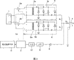
Fig. 2 shows an example according to the amended circuit diagram of electricity removal apparatus of this embodiment;
Fig. 3 shows the sketch map that is used for loading when electricity is eliminated pattern at electricity removal apparatus the example of high-tension method, and wherein electric elimination pattern and park mode can optionally be provided with;
Fig. 4 shows the sketch map that is used for loading when electricity is eliminated pattern at electricity removal apparatus another example of high-tension method, and wherein electric elimination pattern and park mode can optionally be provided with;
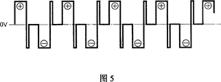
Fig. 5 shows the sketch map that is used for loading when electricity is eliminated pattern at electricity removal apparatus another example of high-tension method, and wherein electric elimination pattern and park mode can optionally be provided with;
Fig. 6 A and 6B show the example of the control model in the park mode, and wherein park mode comprises that pause period and ion produce the cycle; Fig. 6 A shows and in the pause period of park mode, on electrode needle, has loaded the example that does not produce the low level voltage of ion; Fig. 6 B shows in the pause period of park mode not the example to the electrode needle on-load voltage;
Fig. 7 A and 7B show the example of the control model in the park mode, and wherein park mode only comprises pause period and do not comprise that ion produces the cycle; Fig. 7 A shows on the inherent electrode needle of park mode (pause period) and has loaded the example that does not produce the low level voltage of ion; Fig. 7 B shows in park mode (pause period) not the example to the electrode needle on-load voltage;
Fig. 8 show be in park mode when charged main body the internal circuit of electricity removal apparatus with mode identical when being in electric elimination pattern detected the time; Control is eliminated the example of operating through carrying out electricity on loading high voltage to the electrode needle, and shows the example of utilizing threshold value to start and stopping electricity elimination operation;
Fig. 9 shows another example of execution electricity elimination operation when charged main body occurring in the pause period at park mode, and shows the example of utilizing timer to start and stopping electricity elimination operation;
Figure 10 shows and when occurring charged main body in the pause period at park mode, carries out another example that electricity is eliminated operation, and shows and be used for stopping timer that electricity eliminates operation by the example of control changeably;
Figure 11 shows and when occurring charged main body in the pause period at park mode, carries out another example that electricity is eliminated operation, and shows and be used for stopping timer that electricity eliminates operation by another example of control changeably;
Figure 12 shows in the control of when charged main body occurring, carrying out electricity elimination operation, in pause period, on electrode needle, continues the example that loading does not produce the low level voltage of ion;
Figure 13 A and 13B show be in the ion generation cycle stop after or electricity eliminate operation and be carried in the example that the voltage on the electrode needle reduces gradually in transitional period phase I before the pause period after stopping; Figure 13 A shows the example that in pause period, does not have on-load voltage on the electrode needle; Figure 13 B shows and in pause period, on electrode needle, has loaded the example that does not produce the low-voltage of ion;
Figure 14 A and 14B show and are in the second stage that ion after the pause period produces before the cycle or electricity is eliminated before the operation and are carried in the example that the voltage on the electrode needle increases gradually in the transitional period; Figure 14 A shows the example that in pause period, does not have on-load voltage on the electrode needle; Figure 14 B shows and in pause period, on electrode needle, has loaded the example that does not produce the low-voltage of ion;
Figure 15 A and 15B show be in the ion generation cycle stop after or electricity eliminate operation stop after before the pause period transitional period phase I and be in ion after the pause period and produce before the cycle or electricity is eliminated the transitional example of second stage before the operation; Figure 15 A shows the example that in pause period, does not have on-load voltage on the electrode needle; Figure 15 B shows and in pause period, on electrode needle, has loaded the example that does not produce the low-voltage of ion;
Figure 16 shows the electricity removal apparatus among the embodiment; It disposes at the controlled valve or the opening control valve that are used between the external pipe of compressed gas supplying, and this electricity removal apparatus is through providing one to be controlled providing to the Compressed Gas of electricity removal apparatus by the external signal that internal signal produced that is used to control electricity removal apparatus for controlled valve or opening control valve;
Figure 17 shows the diagram that is used to explain an example, in this example, perhaps stops electric elimination operation in order in pause period, when charged main body occurs, to start, and synchronously produces internal signal in electricity removal apparatus inside with startup and termination;
Figure 18 shows the flow chart in the control example shown in Fig. 8; Wherein in the pause period of park mode; When the internal circuitry senses entry of electricity removal apparatus during, carry out electricity and eliminate operation, and electricity is eliminated operation and utilized a threshold value and start or stop to charged main body;
Figure 19 shows the flow chart in the control example shown in Fig. 9; Wherein in the pause period of park mode; When the internal circuitry senses entry of electricity removal apparatus during, carry out electricity and eliminate operation, and electricity is eliminated operation and utilized a threshold value and start and utilize a timer and stop to charged main body;
Figure 20 shows the flow chart in the control example shown in Figure 10; Wherein in the pause period of park mode; When the internal circuitry senses entry of electricity removal apparatus arrives charged main body; Carry out electricity and eliminate operation, and electricity is eliminated operation and utilized a threshold value and start and utilize a timer and stop and the timer time is conditioned;
Figure 21 shows the flow chart in the control example shown in Figure 11; Wherein in the pause period of park mode; When the internal circuitry senses entry of electricity removal apparatus arrives charged main body; Carry out electricity and eliminate operation, and electricity is eliminated operation and utilized a threshold value and start and utilize a timer and stop and the timer time is conditioned;
Figure 22 A and 22B show the diagram that is used to explain an ad hoc approach, and this method is used for controlling the interior ionic equilibrium of electricity removal apparatus of embodiment; Figure 22 A shows the control example when ionic equilibrium is partial to positive side, and Figure 22 B shows the control example when ionic equilibrium deflection minus side;
Figure 23 shows the diagram of the ad hoc approach of the ionic equilibrium in a kind of electricity removal apparatus that is used for controlling embodiment of explanation, and changes the control example of the high-tension mean value of plus or minus through the numerical value corresponding to the ionic equilibrium skew;
Figure 24 shows a flow chart, and this flow chart shows a kind of control example, wherein, in electricity removal apparatus is carried out the pause period of the park mode that comprises ion generation cycle and pause period, stops being carried in the sampling of the magnitude of voltage on the electrode needle; With
Figure 25 shows width of cloth diagram, has explained wherein that when the data of sampling in the ion generation cycle in Figure 24 are stored to memory the transmission that in pause period, is passed to memory can be cancelled by digital processing.
Embodiment
Described according to a preferred embodiment of the invention below with reference to accompanying drawing.
Fig. 1 is the circuit diagram according to the electricity removal apparatus of an embodiment.In Fig. 1, numeral 1 has been represented DC power supply, and it is made up of the external dc power such as storage battery.Numeral 2a and digital 2b have represented first switch and the second switch that is arranged in DC power supply 1 outlet side respectively.The open and close of the first switch 2a and second switch 2b is that the control signal Sa and the Sb of origin Self Control unit 3 controls.Certainly, can be used as the first switch 2a and second switch 2b such as transistorized electronic switch.
The positive pole of DC power supply 1 is connected with first high voltage generation circuit 5 with positive polarity through the first switch 2a, and wherein first high voltage generation circuit 5 comprises transformer 5a and multiple rectifier circuit 5b.On the other hand, the negative pole of DC power supply 1 is connected with second high voltage generation circuit 6 with negative polarity through second switch 2b, and wherein second high voltage generation circuit 6 comprises transformer 6a and multiple rectifier circuit 6b.
High voltage generation circuit 5 and 6 is connected respectively to electrode needle 4 through two resistance R 1 with R1, and wherein the resistance of two resistance R 1 and R1 equates and all as current-limiting impedance.Subsequently, electrode needle 4 is through second resistance R, 2 ground connection.
Come alternately open and close first switch 2a and second switch 2b through utilizing from the control signal Sa and the Sb of control unit 3 outputs, the negative or positive high voltage of impulse form alternately is loaded on the electrode needle 4 with predetermined frequencies from first high voltage generation circuit 5 and second high voltage generation circuit 6.So the plus or minus ion is alternately generated on electrode needle 4.
Control to electricity removal apparatus comprises electric elimination pattern and park mode.In electricity elimination pattern, through on electrode needle 4, loading high voltage to produce ion, promptly on electrode needle 4, load can animating electrode pin 4 ambient airs voltage so that charged main body with electricity fully eliminated.In park mode; Thereby the loading high voltage no longer produces ion on electrode needle 4 through suspending; That is, through on electrode needle 4 not on-load voltage or load one alone the voltage of animating electrode pin 4 ambient airs make electrode needle 4 roughly get into halted state.Electricity elimination pattern and park mode can optionally be set up through a mode selection switch 11 (Fig. 1) of user-operable.
Meanwhile, when in park mode, moving, in the time of before the charged main body that has an electrical potential difference with electrode needle 4 that can self discharge appears at electrode needle 4, the electric charge that has with charged main body opposite polarity is induced at the tip of electrode needle 4.So generation self-discharge phenomenon.Can know the generation of self-discharge phenomenon through the signal that in the internal circuit of electricity removal apparatus, produces.Specifically; There is so a kind of method; The electric current of the electrode needle 4 of flowing through when directly or indirectly detecting self discharge; Between electrode needle 4 and the ground or high voltage generation circuit 5 and 6 with electrode needle 4 between arrange a resistance, and the flow through value of electric current of resistance of detection so just can confirm that self discharge has taken place if the value of electric current is equal to, or greater than a threshold value.Specifically, example comprises that (1) detect electric current in order to detect the self discharge of flowing through between high-voltage power supply and the ground, has inserted a resistance, thereby and the current value that detects the resistance of flowing through indirectly self discharge is detected; (2) for the self discharge that detects between opposite electrode of flowing through (opposite electrode) and the ground detects electric current, inserted a resistance, thereby and the current value that detects the resistance of flowing through directly self discharge is detected; (3) combine (1) and (2), that is, detect electric current in order to detect the self discharge of flowing through between high-voltage power supply and the ground; Inserted a resistance; And detect electric current in order to detect the self discharge of flowing through between opposite electrode and the ground, insert resistance R 2, and detected self discharge thus (Fig. 1); And (4) resistance R 2 is disposed between electrode needle and the high-voltage power supply, thereby and the self discharge that detects the resistance of flowing through detect current value and directly detect self discharge (Fig. 2).
When having adopted above-mentioned self discharge detecting unit (1) to arrive in (3); Promptly; When the self discharge testing circuit of electric current on ground is flowed through in detection, can utilize this circuit in electricity elimination pattern, to eliminate the detecting unit that detects ionic equilibrium at electricity at least so equally as being used for.Specifically; Value for the electric current of each resistance of flowing through; And the value of the total current of these resistance of in this cycle, flowing through; If it is suitable eliminating based on the electricity of the duty ratio between the negative, positive of Set For Current, can think that so this duty ratio is suitable and in next cycle, adopts similar duty ratio.On the other hand; If it is inappropriate eliminating based on the electricity of the duty ratio between the negative, positive of Set For Current; Then should flow through in the cycle value deflection plus or minus of total current of resistance has adopted one recently to carry out electricity more rightly and eliminate through proofreading and correct duty that current duty ratio obtains based on this numerical value in next cycle so.Therefore, electricity removal apparatus is controlled to make the circuit shown in Fig. 1 according to eliminating the data of the current value that use in pattern and the park mode provides by resistance R 2 from the signal of mode selection switch 3 at electricity.Certainly, in park mode, be loaded into 4 last times of electrode needle to high voltage when the purpose of eliminating from electricity and can utilize the current value of the resistance R 2 of flowing through to carry out ionic equilibrium control.
As depicted in figs. 1 and 2, the self discharge of the circuit relevant with self discharge of flowing through detects electric current and is provided to control unit 3 through amplifier 8, low pass filter (LPF) 9 and analog to digital converter (A/D).
As shown in Figure 3, in electricity elimination pattern, the high voltage with impulse form of opposed polarity alternately and constantly is loaded on the electrode needle 4.Fig. 4 and Fig. 5 show the example of the modification that in electricity elimination pattern, moves.As shown in Figure 4, can not load the high-tension time period inserting between high-tension positive side and the ensuing minus side and between minus side and the ensuing positive side, so just prolonged the useful life of electrode needle 4.Also can make another kind of the modification, as shown in Figure 5, wherein produce cation through loading high voltage in positive side; Subsequently, the high voltage of minus side is loaded on the electrode needle 4 and continues a bit of time, subsequently; After a time, produce anion through loading high voltage at minus side in the same way, subsequently; The high voltage of opposite polarity (positive side) is loaded on the electrode needle 4 and continues a bit of time; Subsequently, after after a while, produced cation through loading high voltage in positive side.In the example of another modification, load high-tension method according to shown in Figure 5, can neutralize and remain in the positive voltage in the high voltage load path that leads to electrode needle 4 through producing cation and loading voltage to electrode needle 4 subsequently and continue a bit of times with reversed polarity.In addition, can also reduce extent of corrosion through on electrode needle 4, loading the voltage that is used to neutralize for electrode needle 4.
Certainly; In order to control owing to cation that produces at loading high voltage on the electrode needle 4 and the balance between the anion; For example; When ionic equilibrium during, control and correspondingly increase positive high-tension pulse duration through carrying out duty, thereby can keep the ionic equilibrium of electrode needle 4 surrounding airs at minus side.For example, the open No.2003-86393 of japanese unexamined patent has described ionic equilibrium control in detail, and said disclosed content is incorporated this paper into.In this embodiment, in electricity elimination pattern, be based on one or more duty ratio of the performed mistake in front and confirm duty ratio wherein on electrode needle 4, recently to load high voltage with positive polarity and high voltage with negative polarity according to duty.
In park mode, there is not on-load voltage on the electrode needle 4 fully.Subsequently, during the self discharge that in the current value of second resistance R 2 according to the electricity removal apparatus internal circuit of flowing through detects the pause period of on-load voltage not, taken place, start electricity and eliminate operation.Subsequently, after the electricity that the elapsed time section is perhaps carried out charged main body was later on eliminated completion, operation got into pause period.That is, voltage in park mode on the electrode needle 4 loads and is suspended basically, and has only when detecting charged main body and appear at electricity and eliminate in the zone, and the electricity elimination is operated and just is performed.Subsequently, the elimination of charged main body entering electricity is regional is detected by the internal circuit of electricity removal apparatus.
Below described electric elimination pattern in detail.Fig. 6 and Fig. 7 show the example of the control in the park mode.Fig. 6 A shows as the park mode of first example (1), and Fig. 6 B shows the park mode (2) as second example, and Fig. 7 A shows as the park mode of the 3rd example (3), and Fig. 7 B shows as the park mode of the 4th example (4).
Except not producing ion and being the pause period in predetermined cycle; Control model in park mode (1) shown in Fig. 6 A and Fig. 6 B and (2) also comprises and being in before the pause period and the predetermined afterwards cycle, and produces the cycle through on electrode needle 4, loading the ion that high voltage produces ion.As a kind of method that is used to set those predetermined periods relevant with pause period, some cycles to electricity removal apparatus can be set, perhaps the user can be according to a plurality of pulses or time and optionally is provided with.To producing the method that relevant predetermined period of cycle is set with ion can be set some cycles that are directed to electricity removal apparatus as a kind of being used for, perhaps the user can optionally be provided with according to a plurality of pulses or time.
Control model in park mode (3) shown in Fig. 7 A and Fig. 7 B and (4) only comprises pause period.Therefore, the pause period in the control model in park mode (3) and (4) does not comprise the cycle that those are predetermined, and pause period continues always, up to owing to detect to be recharged and start electricity to the charged main body that surpasses a predetermined value and eliminate and operate.In addition; Referring to Fig. 6 and Fig. 7, in pause period, as long as be recharged to the charged main body that surpasses predetermined value appearance in electricity is eliminated the zone; Just can on electrode needle 4, load the voltage (park mode among Fig. 6 A (1) that does not produce ion; And the park mode among Fig. 7 A (3)), perhaps on electrode needle 4, do not load any voltage (time-out on-load voltage) (park mode among Fig. 6 B (2), and the park mode among Fig. 7 B (4)).
When having adopted the park mode (1) shown in Fig. 6 A and Fig. 7 A and (3); In pause period; On electrode 4, load a voltage that is lower than voltage when discharging beginning and can reduce the electrical potential difference between electrode needle 4 and the charged main body, therefore improved sensitivity slight charged charged main body.
In the park mode (2) shown in Fig. 6 B and Fig. 7 B and (4), in pause period, suspend on electrode needle 4 in the on-load voltage; For example; Suppose and to make that through on electrode needle 4, loading high voltage the magnitude of voltage of electrode needle 4 ambient air ionization is 3kV; Self discharge takes place when surpassing threshold value (for example 3kV) in the electrical potential difference between electrode needle 4 and charged main body on electrode needle 4 in pause period so; And self discharge to (current value of second resistance of flowing through), is eliminated operation so start electricity by the electric circuit inspection in the electricity removal apparatus.For example, eliminating the magnitude of voltage that is carried on the electrode needle 4 in the operation at this electricity is 5.3kV.
In the park mode (1) shown in Fig. 6 A and Fig. 7 A and (3), in pause period, suspend in the voltage that on electrode needle 4, loads one low relatively (for example 2kV); Self discharge takes place when surpassing threshold value (for example 1kV) in the electrical potential difference between electrode needle 4 and charged main body on electrode needle 4 in pause period so; And the current value through second resistance R 2 of flowing through detects self discharge, thereby the high voltage (for example 5.3KV) of ability animating electrode pin 4 surrounding airs is carried in (starting the electricity elimination operates) on the electrode needle 4.It is just the same with the operation described in electricity elimination pattern that this electricity is eliminated operation.According to this mode, in pause period, load a relatively low high voltage and help to increase the sensitivity that charged main body is detected.So, not needing external sensor to detect charged main body and whether get into electricity elimination zone (appearance of charged main body), electricity is eliminated operation and can only in charged main body appearance, utilized the electricity removal apparatus internal circuit to carry out.In other words, owing to can keep absent variable the time forbidding utilizing electrode needle 4 to produce the state of ions when charged main body, the wearing and tearing of electrode 4 have been suppressed like this and to its subsidiary corrosion.
Obviously; Above-mentioned is not a value that is stored in " threshold value " in the memory or similarly knows in advance based on " threshold value " in the control of Fig. 6 and Fig. 7; But in according to the pause period in Fig. 6 and the park mode shown in Figure 7, be carried in the voltage on the electrode needle 4 or do not have the electrical potential difference between the ground and electrode needle 4 in the state that voltage loads and definite, also can be according to the electrical potential difference of ability animating electrode pin 4 ambient airs and definite.Yet, there is not voltage to be carried in 4 last times of electrode needle in the pause period in park mode, threshold value can be equal to, or greater than 3KV, and not necessarily must be 3KV.Similarly, in the pause period in park mode, when having loaded a low relatively high voltage, if the magnitude of voltage that is about to be loaded on the electrode needle 4 is 2KV, threshold value can be equal to or greater than 1KV so, not necessarily must be 1KV.So; According to above-mentioned logic; Said " threshold value " can be fixed value in park mode for electricity removal apparatus; Perhaps through automatically be provided with minimum value as " threshold value " and with maximum as the magnitude of voltage that will in electricity elimination pattern, load, the user can be provided with any one its see fit be in the numerical value conduct " threshold value " between minimum value and the maximum.
As stated; In park mode, can switch to stop pause period and to start electricity eliminating operation, also can carry out switching and eliminate operation and restart pause period to stop electricity according to the value (being exaggerated the absolute value that device 7 amplifies) of the current i of second resistance R 2 (Fig. 1 and Fig. 2) of flowing through according to " threshold value ".Fig. 8 shows the example of control, wherein in the pause period of park mode, detects charged main body and carries out electricity and eliminate operation, and stop electricity and eliminate operation and restart pause period.Referring to Fig. 8, when self discharge detects the absolute value of electric current | when i| surpassed first threshold (for example corresponding to 3KV current value), pause period was terminated and electricity is eliminated the operation beginning.Subsequently, eliminate when the electricity of charged main body and to proceed and self discharge detects the absolute value of electric current | when i| was lower than second threshold value (for example corresponding to the current value that is lower than 1KV), electricity eliminated that operation is terminated and pause period is restarted.In other words, the example of control shown in Figure 8 is such example, and wherein electricity is eliminated the startup of operation and stopped all utilizing threshold value to accomplish in park mode.
Eliminate control as a kind of specific electricity of in park mode, carrying out, its can adopt with the various voltage loading methods that in electricity elimination pattern, carry out that carry out specified otherwise referring to figs. 3 to Fig. 5 in an identical voltage loading method.Certainly, the voltage loading method that is different from the voltage loading method that in electricity elimination pattern, adopts also can adopt in the electricity elimination operation in park mode.
In park mode, after electricity is eliminated operation start utilizing said " threshold value " to make pause period stop, can utilize timer to stop electricity and eliminate operation.Fig. 9 to Figure 11 shows a particular example of this timer.The time t that Fig. 9 shows timer is the example of fixed value, and said time t can be also can being provided with arbitrarily by the user of being provided with when dispatching from the factory.
In the example shown in Figure 10, timer time t can adjust according to the peak value that self discharge detects the absolute value of electric current.In the example shown in Figure 11, the timer time, t can adjust according to slope of a curve, and wherein on behalf of self discharge, this slope detect reducing of current values.
In the adjustment that basis shown in figure 10 " peak value " comes timer time t is carried out, preferably, when " peak value " is big, that is, when charged main body with quantity of electric charge when big, t is provided with longlyer with the timer time; And work as " peak value " hour, that is, and when charged main body with the quantity of electric charge hour, t is provided with shortlyer with the timer time.
In the adjustment that basis shown in figure 11 " slope " comes timer time t is carried out, preferably, when " slope " hour, that is, when charged main body with the quantity of electric charge when slowly reducing, t is provided with longlyer with the timer time; And work as " slope " when big, that is, and when charged main body with the quantity of electric charge when reducing rapidly, t is provided with shortlyer with the timer time.
In Figure 11, show such example at Fig. 8, wherein do not load any voltage (park mode among Fig. 7 (4)) on the electrode needle 4 as park mode.It should be understood, however, that the control model that can adopt other park mode that is suitable for park mode (1), park mode (3) and will describes subsequently equally.Figure 12 shows such example; Wherein " threshold value " is used to start electric the elimination through detection electrified body in the park mode (3) shown in the park mode shown in Fig. 6 A (1) or Fig. 7 A (in these two patterns, a low relatively voltage is loaded on the electrode needle 4 in pause period) and operates and stop electric elimination operation in control.It should be understood, however, that to be similar to Fig. 9, can adopt timer to control the termination that electricity is eliminated operation equally to example shown in Figure 11.
As stated, eliminate operation, loaded high voltage in the operation on the electrode needle 4 and produce ion thereby wherein eliminate at electricity when in pause period, carrying out electricity during to charged main body by the internal circuitry senses entry of electricity removal apparatus.In addition, shown in Fig. 6 A and Fig. 7 A, produce the cycle (high voltage intermittently and periodically is carried on the electrode needle 4) therebetween, can guarantee the electricity that slight charged charged main body is carried out is eliminated through in park mode, comprising ion.At this, in the control model in the park mode (1) shown in Fig. 6 A and Fig. 7 A and (3), ion produces the length in cycle and the length of pause period can at random be provided with.In addition, producing the ratio of time span and the single intermediate ion generation cycle in cycle and the pause period in the single cycle that cycle and pause period subsequently form by ion also can be by setting at random.Time span with the single cycle is an example; For example; If for the transmitting device (transfer conveyer) that carries workpiece (with electricity with the main body that is eliminated) provides electricity removal apparatus, it can be arranged to meet the time span of workpiece transfer beat (transfer tact) so.
When having arranged in the park mode that ion produces the cycle or in park mode, carrying out electricity and eliminating operation, preferably after ion produces cycle (having loaded high voltage on the electrode needle 4 therebetween) or electricity to eliminate EO and increase a transitional period between the pause period.Specifically; When just producing the cycle (or electricity is eliminated operation) when switching to pause period from ion; Arrive before the last moment in ion generation cycle just in next-door neighbour's pause period; Being carried in high-tension polarity on the electrode needle 4 has influenced ionic equilibrium early stage in the pause period in electricity is eliminated the zone, so make ionic equilibrium become uneven.In addition, produce the cycle residual charge that accumulates in (or electricity is eliminated operation) inherent circuit at ion and be loaded on the electrode needle 4, so ion produces and possibly also continue in pause period in pause period.In order to address this problem; Shown in figure 13, preferably be carried on the electrode needle 4 at the voltage that inserted for first transient period before from the ion generation cycle (or electricity elimination operation) to the switching of pause period and then in first transient period, an absolute value is reduced gradually.Figure 13 A shows the example of the control model in the park mode, wherein in pause period, does not have voltage to load on the electrode needle 4 fully.Figure 13 B shows the example of the control model in the park mode, wherein in pause period, on electrode needle 4, has loaded a low level voltage.
Similarly, preferably between the conversion that from the pause period to the ion, produces cycle or electricity elimination operation, increase a transient period.Specifically, when just switching to ion when producing the cycle (or electricity is eliminated operation) from pause period, the main body that needs to eliminate electric charge is exposed to suddenly in the ion, makes the main body that needs to eliminate electric charge be recharged.The result is exactly, and for example, the main body of eliminating electric charge if desired is a semiconductor, then can cause the damage of not expecting to the main body that needs are eliminated electric charge, so will cause in the memory content to be deleted to the rapid charging of main body.In order to address this problem, shown in figure 14, need before the switching that from the pause period to the ion, produces the cycle (or electricity is eliminated operation), insert for second transient period, and the voltage that an absolute value increases gradually is carried on the electrode needle 4.Figure 14 A shows the example of the control model in the park mode, wherein in pause period, does not have voltage to load on the electrode needle 4 fully.Figure 14 B shows the example of the control model in the park mode, wherein in pause period, has loaded a low level voltage on the electrode needle 4.
Figure 15 shows the preferred control example when in park mode, providing ion to produce the cycle; Wherein produce the cycle (or electricity is eliminated operation) from ion and before the switching of pause period, inserted for first transient period, and the switching that from the pause period to the ion, produces the cycle (or electricity is eliminated operation) the next-door neighbour was inserted for second transient period before the next-door neighbour.Figure 15 A shows the example of the control model in the park mode, wherein in pause period, does not have voltage to load on the electrode needle 4 fully.Figure 15 B shows the example of the control model in the park mode, wherein in pause period, has loaded a low level voltage on the electrode needle 4.
In order to be sent to the main body (charged main body) that needs to eliminate electric charge through the ion that loading high voltage on electrode needle 4 produces effectively, generally blow ion to electricity removal apparatus in the practice.Figure 16 shows a kind of electricity removal apparatus 100.Electricity removal apparatus 100 has a plurality of electrode units 12 that comprise above-mentioned electrode needle 4, and electrode unit 12 is with certain spacing arrangement, and filters Compressed Gas and be provided for electricity removal apparatus 100 such as the inert gas of nitrogen through external pipe 13.The filtration Compressed Gas and the inert gas that get into electricity removal apparatus 100 discharge through each electrode unit 12.
External pipe 13 has betwixt electromagnetic switch valve or the electric opening control valve 14 that inserts, and controlled valve or opening control valve 14 are controlled by the output signal Sc from electricity removal apparatus 100.Example to the control of controlled valve or opening control valve 14 can be through making an explanation with reference to Figure 17.In example shown in Figure 17, can clearly find out in the accompanying drawings, stop at on-load voltage on the electrode needle 4 in pause period.When the absolute value of self discharge detection current i became greater than first threshold, operation being activated by the high voltage that is switched to electricity elimination operation and be carried on the electrode needle 4.When the absolute value of self discharge detection current i became greater than first threshold, electricity removal apparatus 100 output signal output Sc were to open electromagnetic switch valve 14.So, switching to when electricity eliminates operation, started the Compressed Gas that electricity removal apparatus 100 is carried out or the supply of inert gas.On the other hand; When the absolute value of self discharge detection current i becomes less than second threshold value; Electricity eliminates that operation stops and pause period is restarted, and simultaneously closed electromagnetic controlled valve 14 with the Compressed Gas that stops electricity removal apparatus 100 is carried out or the supply of inert gas.
As stated; Absolute value or the control signal according to triggering signal through detect current i according to self discharge are exported the triggering signal that a switching that is used between ion generation cycle or electricity elimination operation and the pause period is controlled; For example; Sc controls the gas flow that is provided to electricity removal apparatus 100 according to the output signal, can be so that the consumption of Compressed Gas or inert gas becomes reasonable.If in pause period, loaded a low level voltage on the electrode needle 4; So when transitting to pause period, preferably make that through output signal Sc the opening of opening control valve 14 is littler thereby be fed to the Compressed Gas of electricity removal apparatus 100 or the total amount of inert gas lowers.
In addition; As shown in Figure 6ly comprise that at park mode ion produces under the situation of cycle and pause period; In order to switch to pause period from the ion generation cycle; And switch to ion from pause period and produce the cycle, the signal that electricity removal apparatus 100 in, produces or can be used as according to the control signal that this signal obtains and to export signal Sc and be provided to controlled valve or opening control valve 14 from electricity removal apparatus 100.Under this situation, shown in Fig. 6 B and Fig. 7 B, when not having voltage to load on the electrode needle in the pause period 4 fully, thereby preferably close switch valve 14 stops electricity removal apparatus 100 compressed gas supplying or inert gas.Shown in Fig. 6 A, when having loaded a low level voltage on the electrode needle in the pause period 4, the signal that preferably provides an opening that makes controlled valve 14 to become littler from electricity removal apparatus 100.Can be used to show the current operation status of electricity removal apparatus 100 from the output signal Sc of electricity removal apparatus 100.Specifically; When producing cycle or pause period or its when being in the operation of electric elimination pattern by being configured near the current ion of carrying out of indicating device (not shown) indication electricity removal apparatus 100 on the electricity removal apparatus 100 or it, turning on light and turning off the light of indicating device can be controlled by the output signal Sc that obtains based on the internal signal of control electricity removal apparatus 100.
Through being described to the flow chart of Figure 21 example to some special control with reference to Figure 18.Figure 18 is about eliminating the flow chart that operation is controlled according to " threshold value " among Fig. 8 to electricity in park mode.According to flow chart shown in Figure 180, in step S1, confirm whether park mode is set up, and if answer is yes (park mode is set up), thus then operation entering step S2 measures self discharge detection current i.Whether the absolute value that the self discharge of subsequently, confirming to measure detects current i surpasses first threshold (step S3).If answer is yes,, operation starts electricity elimination operation thereby getting into step S4.Next, in step S5, self discharge is detected current i and detect, and the absolute value that electricity elimination operation lasts till self discharge detection current i always is less than second threshold value.When the absolute value of self discharge detection current i became less than second threshold value, electricity was eliminated and is operated in step S6 termination.So electricity removal apparatus gets into the pause period of park mode again, and be the monitoring of proceeding of self discharge, and electricity is eliminated to operate in and is in SBR in the halted state to the appearance of charged main body.
Flow chart among Figure 19 is wherein eliminated operation through using timer to stop electricity corresponding to control shown in Figure 9.According to flow chart shown in Figure 19, in step S10, confirm whether park mode is set up, and if answer is yes (park mode is set up), and then measure self discharge and detect current i at step S11; And whether the absolute value that the self discharge of confirming to measure detects current i surpasses first threshold (step S12).If answer is yes, thereby then operation gets into step S13 startup electricity elimination operation.Next, timer is activated in step S14, and when the time of timer t arrived scheduled time t0, operation got into step S15 and stops electricity elimination operation.So electricity removal apparatus is back to the pause period of park mode.So electricity removal apparatus gets into the pause period of park mode again, and be the monitoring of proceeding of self discharge to the appearance of charged main body.
Flow chart among Figure 20 is corresponding to control shown in Figure 10, and wherein the timer time is variable.According to flow chart shown in Figure 20, in step S20, confirm whether park mode is set up, and if answer is yes (park mode is set up), and then measure self discharge and detect current i at step S21; And whether the absolute value that the self discharge of confirming to measure detects current i surpasses first threshold (step S22).If answer is yes,, operation starts electricity elimination operation thereby getting into step S23.Subsequently, detect current i in step 24 pair self discharge and measure, detect the peak value (step 25) that current i is measured earth current according to self discharge, and from a data form, obtain timer time t0 (step 26) corresponding to peak value.Next, the timer time is configured to time t0 and timer is activated (step 27), and when the time of timer t arrived the scheduled time t0 (step 28) that is set up, electricity was eliminated operation and is terminated (step 29).So electricity removal apparatus is back to the pause period of park mode.So electricity removal apparatus gets into the pause period of park mode again, and be the monitoring of proceeding of self discharge to the appearance of charged main body.
Flow chart among Figure 21 is corresponding to control shown in Figure 11.According to flow chart shown in Figure 21, in step S30, confirm whether park mode is set up, and if answer is yes (park mode is set up), and then measure self discharge and detect current i at step S31; And whether the absolute value that the self discharge of confirming to measure detects current i surpasses first threshold (step S32).If answer is yes,, operation starts electricity elimination operation thereby getting into step S33.Subsequently, detect current i in step 34 pair self discharge and measure, detect the peak value (step 35) that current i is measured earth current according to self discharge.After having detected peak value, operation gets into step S36 and detects current i to measure self discharge, and from the derivative value of self discharge detection current i, obtains a slope (step 37).Subsequently, from a data form, obtain timer time t0 (step 38) corresponding to the gained slope.Next, the timer time is configured to time t0 and timer is activated (step 39), and when the time of timer t arrived the scheduled time t0 (step 40) that is set up, electricity was eliminated operation and is terminated (step 41).So electricity removal apparatus is back to the pause period of park mode.So electricity removal apparatus gets into the pause period of park mode again, and be the monitoring of proceeding of self discharge to the appearance of charged main body.
In above-mentioned electricity removal apparatus 100, when the ionic equilibrium in electricity is eliminated the zone in the operating period of park mode skew takes place, preferably, can suitably carry out such as Figure 22 and control shown in Figure 23 with the maintenance ionic equilibrium.Ionic equilibrium control shown in Figure 22 is the control (duty ratio control) that has changed the high-tension pulse duration of pulse type that is carried on the electrode needle 4.Figure 22 A shows the example of the control when near the ionic equilibrium the electrode needle 4 is partial to positive side.Under this situation, control and make that the positive high-tension pulse duration of loading is less.Figure 22 B shows the example of the control when near the deflection of the ionic equilibrium the electrode needle 4 minus side.Under this situation, control and make that the positive high-tension pulse duration of loading is bigger.
The example of control shown in Figure 22 is to come suitably to keep the example of ionic equilibrium through changing high-tension pulse duration, but the high-tension value positive or that bear that is carried on the electrode needle 4 also can be changed.In addition, shown in figure 23, voltage can be controlled to the degree of positive or negative high-tension mean value corresponding to the ionic equilibrium skew that make.Certainly, this value can be digitized ground on average.When in park mode, carrying out such ionic equilibrium control, need carry out suitable sampling to the high voltage positive or that bear that is carried on the electrode needle 4.In addition, preferably utilize a suitable averaging to come to carry out rightly ionic equilibrium control.
Give detailed explanation with regard to this point at present.Thereby ionic equilibrium control be want positive side high voltage and the minus side high voltage of control loaded on electrode needle 4 make the balance of electrode needle 4 cation and anion on every side can neutralize rightly charged main body with.In this ionic equilibrium control; Recently carry out under the situation of ionic equilibrium control utilizing duty between positive voltage and the negative voltage; For example ought be with the main body of positive electricity when having got into electric elimination zone, the to be detected and high voltage that is adjusted to the duty ratio that has increased minus side of this state of charge is loaded on the electrode needle 4.In order to carry out control rightly, the current at least duty ratio that is used to carry out control and as the state that current control result's electricity is eliminated ionic equilibrium in the zone preferably migrate (reflect) in control next time, be carried in the confirming of high-tension duty ratio on the electrode needle 4.
As stated, park mode comprises pause period, in pause period, does not produce ion around the electrode needle 4.When being converted to ion from pause period and producing the cycle, perhaps when pause period is converted to electricity and eliminates operation, the current duty ratio that is used to carry out control is not existing basically.So, be right after be converted to ion produce cycle or electricity eliminate operation after and in pause period duty ratio migrate possibly be easy to become in the ionic equilibrium control and cause being right after being converted to that ion produces the cycle or electricity is eliminated the operation inappropriate reason of ionic equilibrium afterwards.
In addition; When having adopted such method; Wherein there is not to load the high voltage that is used for ionization in the pause period in park mode on the electrode needle 4; At this moment in order to optimize the data that are used for ionic equilibrium control that comprise pause period, the proper one or more legacy data that will store before this exactly is average.Yet, the data that comprise the data in the pause period averaged to be easy to become cause the inappropriate reason of ionic equilibrium when being converted to ion and producing cycle or electricity and eliminate operation.Specifically, generally for electricity removal apparatus, the positive polarity high voltage and the duty ratio between the negative high-voltage that are carried on the electrode needle 4 are confirmed according to used one or more duty ratios before being close to this time.Yet, in the time of in using the park mode that is comprising pause period, want to be provided with a suitable duty ratio and very maybe not.For fear of this problem, shown in the flow chart among Figure 24, preferably stop the sampling in the pause period, and last data that the electricity of the ion generation cycle of employing front or front is eliminated in the operation are controlled to the loading of voltage on the electrode needle 4.In addition, in order to optimize the ionic equilibrium control in the high voltage loading, preferably that the data of front are average.
Figure 24 produces the park mode (1) in cycle and the execution flow process of park mode (2) according to comprise pause period and the ion shown in Fig. 6 A and the 6B.At first, be opened, subsequently, determine whether it is that ion produces the cycle at step S51 at step S50 high voltage appearance power supply.If answer is yes, that is, produced ion through on electrode needle 4, loading high voltage, then operation gets into step S52.For example positive side and the high-tension duty ratio of minus side to being carried on the electrode needle 4 are sampled, and shown in figure 25 being stored in the memory.Subsequently,, calculate a mean value, and mean value is stored in the memory and according to mean value carries out ionic equilibrium control according to the sampled data piece of predetermined number at step S53.
When switching to pause period from the ion generation cycle, operation gets into step S54 to close high-voltage power supply from step S51.Subsequently, at step S55, the numerical value that is carried in the voltage on the electrode needle 4 or its duty ratio of using in confirming to carry out according to the numerical value of being stored in the memory next time, and with determined storage in memory.After pause period finishes, be loaded on the electrode needle 4 from high-voltage power supply according to the high voltage of determined numerical value in pause period or duty ratio.Specifically, for example in pause period, the sampling of duty ratio is not performed.Figure 25 shows the example of digital processing, and forbidden data transfers to memory in pause period.
For control is optimized to ionic equilibrium after the generation cycle and then be converted to ion from pause period; The ionic equilibrium of electricity in the pause period being eliminated the zone detects and it is stored in the memory; And these will be brought in constant renewal in pause period; And the data of the ionic equilibrium in pause period interpolation in latter stage electricity elimination zone; And proofread and correct in determined high-tension data of pause period or duty ratio above-mentioned, therefore can load and control high voltage subsequently.
So, can confirm and then to be converted to ion is suitable for ionic equilibrium control after the generation cycle duty ratio or high-voltage level from pause period.In not comprising the ion park mode in generation cycle (Fig. 7 A and Fig. 7 B); Preferably; Eliminate in the operation at electricity nearest duty ratio or nearest high-voltage value as the result of ionic equilibrium control are carried out continuous sampling to store; And just before the beginning electricity is eliminated operation, the data of eliminating storage in the operation at nearest electricity are averaged to confirm to be carried in value or its duty ratio of the voltage on the electrode needle 4.So, can avoid averaging in the pause period that loads no-voltage.In addition; Can detect in the pause period electricity eliminates the ionic equilibrium in zone and it is stored in the memory; And these will be brought in constant renewal in pause period; Be converted to the data that obtain before the electricity elimination operation according to being close to, the data that are determined can be corrected into high-tension value or its duty ratio of soon carrying out on the above-mentioned electrode needle 4 that be carried in.
The ionic equilibrium control that ion produced in the cycle can be such; For example be converted to the commitment of ion after the generation cycle; At first; According to the high-tension value of in pause period, confirming or its duty recently with a positive or negative voltage as estimating control loaded on electrode needle 4, and in ionic equilibrium control subsequently, can carry out with electric elimination pattern in identical ionic equilibrium control; That is the high-tension value of plus or minus or its duty ratio, confirming to be carried on the electrode needle 4 through the electric current of the internal circuit of flowing through also and then based on the performed ionic equilibrium of FEEDBACK CONTROL are controlled to carry out FEEDBACK CONTROL.Specifically, produce the commitment in cycle, carry out as the ionic equilibrium control of estimating control, and switch to FEEDBACK CONTROL in ionic equilibrium control intermediate ion Balance Control subsequently according to established data in pause period at ion.In addition; Example as a modification; Preferably, produce the commitment in cycle, carry out as the ionic equilibrium control of estimating control according to established data in pause period at ion; And subsequently, carrying out ionic equilibrium according to the electric current of the internal circuit of flowing through controls and according to established data in pause period data is proofreaied and correct simultaneously.
In not comprising the ion park mode in generation cycle (Fig. 7 A and Fig. 7 B); Preferably; The ionic equilibrium storage of value and the sense of current of electric current of eliminating the relevant internal circuit of flowing through of ionization equilibrium in the operation with the electricity of pause period in memory; For example, be utilized in an electricity and eliminate and on electrode needle 4, to load the ionic equilibrium control that ionic equilibrium data that high voltage obtained are carried out commitment in the operation, carry out next electricity and eliminate operation; And ionic equilibrium control can be switched to FEEDBACK CONTROL as above, carries out according to this.Equally preferably; Be utilized in electricity and eliminate the data of storage in the operation; Eliminate the operation commitment at next electricity and carry out, thereby and proofread and correct according to the electric current of the internal circuit of flowing through subsequently and carry out ionic equilibrium control (for example duty ratio control) as the ionic equilibrium control of estimating control.
As stated, be utilized on the public electrode pin 4 and load the example that opposite polarity voltage comes alternately to produce negative ions embodiment is illustrated.Yet; It should be understood that; The present invention can also be applied in the following electricity removal apparatus, thus wherein the pair of electrodes pin be loaded positive high voltage and negative high-voltage respectively as described in the Figure 16 of the open No.2000-58290 of japanese unexamined patent and embodiment shown in Figure 17 ground produce cation and anion.Specifically, the self discharge testing circuit can be disposed in respectively between positive and negative electrode pin and the ground, and when detecting self discharge on any one electrode needle, can be loaded on the electrode needle to carry out electricity elimination operation with high voltage same in electricity elimination pattern.In addition, it should be understood that in the pause period of park mode, can on electrode needle, load a voltage that does not produce ion, that is, can improve the voltage (for example 2kV) of the sensitivity that charged main body is detected.
Claims (16)
1. electricity removal apparatus, said electricity removal apparatus is through producing the ion charged main body that neutralizes, and said electricity removal apparatus comprises:
Electrode is used for producing ion;
Potential circuit, it is connected to said electrode, is used for producing positive voltage and negative voltage and comes for said electrode electric energy to be provided;
The self discharge testing circuit is used to detect the self discharge of said electrode; And
Control unit is used to control the positive voltage and the negative voltage that are produced by said potential circuit, makes it be in said electrode and does not initiatively produce in first state of ion and second state that said electrode initiatively produces ion; Be used for when said self discharge testing circuit detects self discharge, will convert electrode voltage to corresponding to the electrode voltage of first state corresponding to second state; And be used for when satisfying the condition that stops, will converting electrode voltage to corresponding to the electrode voltage of second state corresponding to first state.
2. electricity removal apparatus as claimed in claim 1, wherein
The circuit that the value that is used for being arranged in flowing through the electric current of the resistance between said electrode and the said potential circuit of comprising said self discharge testing circuit detects.
3. electricity removal apparatus as claimed in claim 1, wherein
The circuit that the value that is used for being arranged in flowing through the electric current of the resistance between said electrode and the ground of comprising said self discharge testing circuit detects.
4. electricity removal apparatus as claimed in claim 2, wherein
Said self discharge testing circuit comprises and is used to detect the part of electric current absolute value of resistance of flowing through, and when said absolute value surpasses first threshold, then thinks to detect self discharge.
5. electricity removal apparatus as claimed in claim 2, wherein
Said control unit confirm the to flow through absolute value of electric current of resistance is then thought when said absolute value is lower than second threshold value and is satisfied end condition.
6. electricity removal apparatus as claimed in claim 1, wherein
Control unit is confirmed as process predetermined amount of time after switching to corresponding to the electrode voltage of second state from the electrode voltage corresponding to first state and is satisfied end condition.
7. electricity removal apparatus as claimed in claim 2 also comprises:
Peak detection unit, its peak value to the electric current of the said resistance of flowing through detects, wherein
Said control unit is confirmed as process predetermined amount of time after switching to corresponding to the electrode voltage of second state from the electrode voltage corresponding to first state and is satisfied end condition; And
According to regulating the preset time section by the order of magnitude of the detected peak value of said peak detection unit; So; When said absolute value is big, be compared to said absolute value situation hour and prolong the preset time section, and hour be compared to the situation shortening preset time section of said absolute value when big when said absolute value.
8. electricity removal apparatus as claimed in claim 2 also comprises:
Peak detection unit, its peak value to the electric current of the said resistance of flowing through detects, and
Electric current reduces speed detection unit, and it is used for when the absolute value of the current peak of the said resistance of flowing through diminishes gradually, and the speed that absolute value is reduced detects, wherein
Said control unit is confirmed as process predetermined amount of time after switching to corresponding to the electrode voltage of second state from the electrode voltage corresponding to first state and is satisfied end condition; And
Regulate the preset time section according to reduce speed detection unit detected speed that reduces when the absolute value of peak value reduces by said electric current; So; When the said speed that reduces hour is compared to the said situation said preset time section of speed when big that reduce and is extended, and be compared to the said speed said preset time section of situation hour that reduces when big and be shortened when the said speed that reduces.
9. electricity removal apparatus as claimed in claim 1, wherein
Corresponding to the electrode voltage of first state is to be in potential circuit to electrode the electrode voltage under the state of any voltage not to be provided.
10. electricity removal apparatus as claimed in claim 1, wherein
Electrode voltage corresponding to first state is to be in the electrode voltage of potential circuit under the state that loads the voltage that does not produce ion on the electrode.
11. electricity removal apparatus as claimed in claim 1, wherein
When satisfying end condition, control unit will be reduced to the electrode voltage corresponding to first state corresponding to the electrode voltage of second state gradually.
12. electricity removal apparatus as claimed in claim 1, wherein
When the self discharge testing circuit detects self discharge, control unit will increase to the electrode voltage corresponding to second state gradually corresponding to the electrode voltage of first state.
13. electricity removal apparatus as claimed in claim 1 also comprises
Mode selector; Be used for manually selecting from the group that comprises first pattern and second pattern; Wherein in said first pattern, even control unit will be kept the electrode voltage corresponding to second state when satisfying end condition, and in second pattern; When satisfying end condition, control unit will switch to the electrode voltage corresponding to first state corresponding to the electrode voltage of second state.
14. electricity removal apparatus as claimed in claim 1 also comprises
First output unit, it is used for when the self discharge testing circuit detects self discharge, producing first signal and exports first signal to external devices.
15. electricity removal apparatus as claimed in claim 1 also comprises
Second output unit, it is used for when satisfying end condition, producing secondary signal and exports secondary signal to external devices.
16. electricity removal apparatus as claimed in claim 1 also comprises
The ionic equilibrium controller, its be used for regulating with the corresponding electrode voltage of second state with the control ionic equilibrium;
Memory, it is used to store the electrode voltage corresponding to second state by after the adjusting of ionic equilibrium controller; And
Confirm the unit, it is used for confirming the positive voltage and the negative voltage that will provide for electrode according to the electrode voltage corresponding to second state that is stored in memory;
Wherein, when the self discharge testing circuit detects self discharge, potential circuit is controlled will confirm that determined positive voltage in unit and negative voltage offer electrode.
Applications Claiming Priority (3)
| Application Number | Priority Date | Filing Date | Title |
|---|---|---|---|
| JP2006343067A JP4919794B2 (en) | 2006-12-20 | 2006-12-20 | Static eliminator |
| JP2006343067 | 2006-12-20 | ||
| JP2006-343067 | 2006-12-20 |
Publications (2)
| Publication Number | Publication Date |
|---|---|
| CN101207964A CN101207964A (en) | 2008-06-25 |
| CN101207964B true CN101207964B (en) | 2012-08-29 |
Family
ID=39567736
Family Applications (1)
| Application Number | Title | Priority Date | Filing Date |
|---|---|---|---|
| CN2007103022178A Expired - Fee Related CN101207964B (en) | 2006-12-20 | 2007-12-20 | Electricity removal apparatus |
Country Status (4)
| Country | Link |
|---|---|
| JP (1) | JP4919794B2 (en) |
| KR (1) | KR101162400B1 (en) |
| CN (1) | CN101207964B (en) |
| TW (1) | TWI442834B (en) |
Families Citing this family (13)
| Publication number | Priority date | Publication date | Assignee | Title |
|---|---|---|---|---|
| US8885317B2 (en) * | 2011-02-08 | 2014-11-11 | Illinois Tool Works Inc. | Micropulse bipolar corona ionizer and method |
| US9380689B2 (en) | 2008-06-18 | 2016-06-28 | Illinois Tool Works Inc. | Silicon based charge neutralization systems |
| CN102106051B (en) * | 2008-08-01 | 2015-03-25 | 夏普株式会社 | Lighting device |
| JP2010146844A (en) * | 2008-12-18 | 2010-07-01 | Midori Anzen Co Ltd | Static eliminator |
| JP4770953B2 (en) * | 2009-03-13 | 2011-09-14 | オムロン株式会社 | Static eliminator |
| USD743017S1 (en) | 2012-02-06 | 2015-11-10 | Illinois Tool Works Inc. | Linear ionizing bar |
| US9125284B2 (en) | 2012-02-06 | 2015-09-01 | Illinois Tool Works Inc. | Automatically balanced micro-pulsed ionizing blower |
| US9918374B2 (en) | 2012-02-06 | 2018-03-13 | Illinois Tool Works Inc. | Control system of a balanced micro-pulsed ionizer blower |
| JP5734924B2 (en) * | 2012-07-11 | 2015-06-17 | シシド静電気株式会社 | Ion generator and discharge electrode mounting state monitoring method |
| JP5945970B2 (en) * | 2013-10-23 | 2016-07-05 | Smc株式会社 | Ionizer and control method thereof |
| CN103716976B (en) * | 2013-12-31 | 2016-06-15 | 上海安平静电科技有限公司 | A kind of realize the eliminostatic device that single pin alternately exports positive and negative high direct voltage |
| JP6399402B2 (en) * | 2015-02-20 | 2018-10-03 | Smc株式会社 | Ionizer |
| JP6778762B2 (en) * | 2017-01-10 | 2020-11-04 | 株式会社Fuji | Work machine |
Citations (5)
| Publication number | Priority date | Publication date | Assignee | Title |
|---|---|---|---|---|
| US4901194A (en) * | 1988-07-20 | 1990-02-13 | Ion Systems, Inc. | Method and apparatus for regulating air ionization |
| CN1578582A (en) * | 2003-07-22 | 2005-02-09 | 株式会社Trinc | Static eliminator |
| CN1592535A (en) * | 2003-07-29 | 2005-03-09 | 东丽株式会社 | Static eliminator and a static eliminating method for an insulating sheet, a method for producing an insulating sheet, and an insulating sheet |
| CN1649467A (en) * | 2004-01-19 | 2005-08-03 | 株式会社其恩斯 | Static eliminator |
| CN101031178A (en) * | 2006-03-02 | 2007-09-05 | 株式会社Trinc | Plasma discharged static eliminator |
Family Cites Families (6)
| Publication number | Priority date | Publication date | Assignee | Title |
|---|---|---|---|---|
| JP2003068497A (en) | 2001-08-29 | 2003-03-07 | Kasuga Electric Works Ltd | Control method and control device of direct current antistatic device |
| JP2004207150A (en) | 2002-12-26 | 2004-07-22 | Sunx Ltd | Destaticizing device |
| JP2006007012A (en) * | 2004-06-22 | 2006-01-12 | Koganei Corp | Charge removal/dedusting apparatus |
| JP2006315770A (en) * | 2005-05-10 | 2006-11-24 | Murata Mach Ltd | Doffing device for automatic winder |
| JP4111348B2 (en) | 2006-11-29 | 2008-07-02 | ヒューグルエレクトロニクス株式会社 | Static eliminator |
| JP4770953B2 (en) | 2009-03-13 | 2011-09-14 | オムロン株式会社 | Static eliminator |
-
2006
- 2006-12-20 JP JP2006343067A patent/JP4919794B2/en not_active Expired - Fee Related
-
2007
- 2007-12-12 TW TW096147420A patent/TWI442834B/en not_active IP Right Cessation
- 2007-12-13 KR KR1020070129768A patent/KR101162400B1/en not_active IP Right Cessation
- 2007-12-20 CN CN2007103022178A patent/CN101207964B/en not_active Expired - Fee Related
Patent Citations (5)
| Publication number | Priority date | Publication date | Assignee | Title |
|---|---|---|---|---|
| US4901194A (en) * | 1988-07-20 | 1990-02-13 | Ion Systems, Inc. | Method and apparatus for regulating air ionization |
| CN1578582A (en) * | 2003-07-22 | 2005-02-09 | 株式会社Trinc | Static eliminator |
| CN1592535A (en) * | 2003-07-29 | 2005-03-09 | 东丽株式会社 | Static eliminator and a static eliminating method for an insulating sheet, a method for producing an insulating sheet, and an insulating sheet |
| CN1649467A (en) * | 2004-01-19 | 2005-08-03 | 株式会社其恩斯 | Static eliminator |
| CN101031178A (en) * | 2006-03-02 | 2007-09-05 | 株式会社Trinc | Plasma discharged static eliminator |
Also Published As
| Publication number | Publication date |
|---|---|
| CN101207964A (en) | 2008-06-25 |
| JP4919794B2 (en) | 2012-04-18 |
| JP2008159272A (en) | 2008-07-10 |
| KR20080058187A (en) | 2008-06-25 |
| KR101162400B1 (en) | 2012-07-05 |
| TWI442834B (en) | 2014-06-21 |
| TW200843563A (en) | 2008-11-01 |
Similar Documents
| Publication | Publication Date | Title |
|---|---|---|
| CN101207964B (en) | Electricity removal apparatus | |
| US8228042B2 (en) | Battery pack charging method | |
| US8098053B2 (en) | Charger for lithium ion secondary battery, and method of charging the same | |
| CN100364206C (en) | Constant-current battery charger | |
| US7649728B2 (en) | Electricity removal apparatus | |
| CN102082458B (en) | Inverter intelligent charging control method | |
| JP2005534276A (en) | Battery charger | |
| CN103151815B (en) | Method for controlling equalizing charge of elementary cell of battery pack | |
| CN104770884A (en) | Electronic cigarette control chip and electronic cigarette | |
| JPS6125650A (en) | Method for controlling electrical charge of electrical dust precipitator | |
| TW370733B (en) | Method and apparatus for charging secondary battery | |
| US20080185998A1 (en) | Method of charging double electric layer electrochemical capacitors | |
| CN203278327U (en) | Backup power supply charging and discharging control circuit | |
| JP2008159273A (en) | Static eliminator | |
| CN204426703U (en) | Electronic cigarette control chip and electronic cigarette | |
| US11342776B2 (en) | Battery charger and method for charging a battery | |
| CN102281686B (en) | Compensation control device for LED (Light Emitting Diode) lamp during rapid falling of input voltage and method thereof | |
| CN103424715A (en) | Lamp testing circuit and device | |
| CN101172313A (en) | No power consumption safe standby energy-saving control device of electric welding machine | |
| JPH10174305A (en) | Battery charger | |
| JPH01123647A (en) | Controlling method for reverse ionization of electrostatic precipitator | |
| KR100950588B1 (en) | Apparatus for recharging a module of electric double layer capacitors | |
| CN202094861U (en) | Automatic energy-saving control switch | |
| JPH08317574A (en) | Quick charger circuit | |
| JP2008159271A (en) | Static eliminator |
Legal Events
| Date | Code | Title | Description |
|---|---|---|---|
| C06 | Publication | ||
| PB01 | Publication | ||
| C10 | Entry into substantive examination | ||
| SE01 | Entry into force of request for substantive examination | ||
| C14 | Grant of patent or utility model | ||
| GR01 | Patent grant | ||
| CF01 | Termination of patent right due to non-payment of annual fee |
Granted publication date: 20120829 Termination date: 20141220 |
|
| EXPY | Termination of patent right or utility model |