CN101201023B - Throttle valve controller for internal combustion engine - Google Patents
Throttle valve controller for internal combustion engine Download PDFInfo
- Publication number
- CN101201023B CN101201023B CN2007101620834A CN200710162083A CN101201023B CN 101201023 B CN101201023 B CN 101201023B CN 2007101620834 A CN2007101620834 A CN 2007101620834A CN 200710162083 A CN200710162083 A CN 200710162083A CN 101201023 B CN101201023 B CN 101201023B
- Authority
- CN
- China
- Prior art keywords
- lower limit
- throttle valve
- amplitude limit
- limit value
- combustion engine
- Prior art date
- Legal status (The legal status is an assumption and is not a legal conclusion. Google has not performed a legal analysis and makes no representation as to the accuracy of the status listed.)
- Active
Links
Images


Classifications
-
- F—MECHANICAL ENGINEERING; LIGHTING; HEATING; WEAPONS; BLASTING
- F02—COMBUSTION ENGINES; HOT-GAS OR COMBUSTION-PRODUCT ENGINE PLANTS
- F02D—CONTROLLING COMBUSTION ENGINES
- F02D11/00—Arrangements for, or adaptations to, non-automatic engine control initiation means, e.g. operator initiated
- F02D11/06—Arrangements for, or adaptations to, non-automatic engine control initiation means, e.g. operator initiated characterised by non-mechanical control linkages, e.g. fluid control linkages or by control linkages with power drive or assistance
- F02D11/10—Arrangements for, or adaptations to, non-automatic engine control initiation means, e.g. operator initiated characterised by non-mechanical control linkages, e.g. fluid control linkages or by control linkages with power drive or assistance of the electric type
- F02D11/105—Arrangements for, or adaptations to, non-automatic engine control initiation means, e.g. operator initiated characterised by non-mechanical control linkages, e.g. fluid control linkages or by control linkages with power drive or assistance of the electric type characterised by the function converting demand to actuation, e.g. a map indicating relations between an accelerator pedal position and throttle valve opening or target engine torque
-
- F—MECHANICAL ENGINEERING; LIGHTING; HEATING; WEAPONS; BLASTING
- F02—COMBUSTION ENGINES; HOT-GAS OR COMBUSTION-PRODUCT ENGINE PLANTS
- F02D—CONTROLLING COMBUSTION ENGINES
- F02D11/00—Arrangements for, or adaptations to, non-automatic engine control initiation means, e.g. operator initiated
- F02D11/06—Arrangements for, or adaptations to, non-automatic engine control initiation means, e.g. operator initiated characterised by non-mechanical control linkages, e.g. fluid control linkages or by control linkages with power drive or assistance
- F02D11/10—Arrangements for, or adaptations to, non-automatic engine control initiation means, e.g. operator initiated characterised by non-mechanical control linkages, e.g. fluid control linkages or by control linkages with power drive or assistance of the electric type
- F02D11/107—Safety-related aspects
-
- F—MECHANICAL ENGINEERING; LIGHTING; HEATING; WEAPONS; BLASTING
- F02—COMBUSTION ENGINES; HOT-GAS OR COMBUSTION-PRODUCT ENGINE PLANTS
- F02D—CONTROLLING COMBUSTION ENGINES
- F02D41/00—Electrical control of supply of combustible mixture or its constituents
- F02D41/20—Output circuits, e.g. for controlling currents in command coils
- F02D2041/202—Output circuits, e.g. for controlling currents in command coils characterised by the control of the circuit
- F02D2041/2048—Output circuits, e.g. for controlling currents in command coils characterised by the control of the circuit said control involving a limitation, e.g. applying current or voltage limits
-
- F—MECHANICAL ENGINEERING; LIGHTING; HEATING; WEAPONS; BLASTING
- F02—COMBUSTION ENGINES; HOT-GAS OR COMBUSTION-PRODUCT ENGINE PLANTS
- F02D—CONTROLLING COMBUSTION ENGINES
- F02D2250/00—Engine control related to specific problems or objectives
- F02D2250/16—End position calibration, i.e. calculation or measurement of actuator end positions, e.g. for throttle or its driving actuator
-
- F—MECHANICAL ENGINEERING; LIGHTING; HEATING; WEAPONS; BLASTING
- F02—COMBUSTION ENGINES; HOT-GAS OR COMBUSTION-PRODUCT ENGINE PLANTS
- F02D—CONTROLLING COMBUSTION ENGINES
- F02D41/00—Electrical control of supply of combustible mixture or its constituents
- F02D41/24—Electrical control of supply of combustible mixture or its constituents characterised by the use of digital means
- F02D41/2406—Electrical control of supply of combustible mixture or its constituents characterised by the use of digital means using essentially read only memories
- F02D41/2425—Particular ways of programming the data
- F02D41/2429—Methods of calibrating or learning
- F02D41/2451—Methods of calibrating or learning characterised by what is learned or calibrated
- F02D41/2464—Characteristics of actuators
Landscapes
- Engineering & Computer Science (AREA)
- Chemical & Material Sciences (AREA)
- Combustion & Propulsion (AREA)
- Mechanical Engineering (AREA)
- General Engineering & Computer Science (AREA)
- Electrical Control Of Air Or Fuel Supplied To Internal-Combustion Engine (AREA)
- Control Of Throttle Valves Provided In The Intake System Or In The Exhaust System (AREA)
- Control Of Vehicle Engines Or Engines For Specific Uses (AREA)
Abstract
If a throttle valve is moved toward the mechanical full close position at high speed, the throttle valve may overshoot and collide against the full close position. This may damage and deform the throttle valve. It is an object of the present invention to set a lower limiter to the throttle valve so as to secure a margin to prevent such collision while attaining lowered fuel consumption or improved fuel efficiency. The above-mentioned object is attained by a throttle valve controller for an internal combustion engine, which comprises: a throttle valve which is driven by a motor; means for determining the target opening of the throttle valve based on the operating state of the vehicle or internal combustion engine; a first lower limit which is determined beforehand as the minimum target opening; and means for setting a second lower limit which is smaller than the first lower limit if the determined target opening is smaller than a predetermined opening and/or if the rotation speed of the internal combustion engine is lower than a predetermined speed.
Description
Technical field
The present invention relates to the airflow control of internal-combustion engine.
Background technique
In patent documentation 1, describe following technology is arranged: lower limit amplitude limit (limiter) is made as 2 grades, when the actual aperture of throttle valve from opening state when full-shut position moves, drop to be set at the amplitude limit of slightly opening after, with certain speed, drop to the technology that is set at the lower limit amplitude limit value of slightly closing.
Patent documentation 1: Japanese kokai publication hei 8-74639 communique
If make the full close position high-speed motion of throttle valve to machinery, owing to produce very big impact force when down hitting full close position in a state of excitement, faults such as apt to cause breakage, distortion.For fear of above-mentioned breakage, distortion etc.,, set flexible target aperture lower limit amplitude limit in the position of fully guaranteeing the excess room that throttle valve is opened of the mechanical full close position of distance.On the other hand, at the wide vehicle of the output control range of motor, particularly in the low oil consumption car that comprises HEV car, CVT employing car etc., in order to seek further to improve fuel efficiency, rotating speed than lowland when idle running control etc. is arranged, promptly reduce required air quantity, reduce the requirement of lower limit amplitude limit.
Summary of the invention
The objective of the invention is to, realize simultaneously guaranteeing to avoid above-mentioned throttle valve, and seek above-mentioned low oil consumption, high fuel efficiency in the breakage at full close position place, the excess room of distortion.
The following solution of above-mentioned problem provides a kind of airflow control of internal-combustion engine, it is characterized in that having: by electric motor driven throttle valve; Obtain the device of the target aperture of described throttle valve according to the operating condition of vehicle or internal-combustion engine; And setting device, it has as the first lower limit amplitude limit value lower limit of described target aperture, predefined, and in described target aperture of trying to achieve or internal-combustion engine rotational speed any is less than preset value at least the time, set second amplitude limit value less than the described first lower limit amplitude limit value.
In addition, the following solution of above-mentioned problem provides a kind of airflow control of internal-combustion engine, it is characterized in that having: by electric motor driven throttle valve; Obtain the device of the target aperture and the target aperture pace of change of described throttle valve according to the operating condition of vehicle or internal-combustion engine; And setting device, it has as the first lower limit amplitude limit value lower limit of described target aperture, predefined, and when described target aperture pace of change of trying to achieve is lower than preset value, sets second amplitude limit value less than the described first lower limit amplitude limit value.
The invention effect
The present invention uses throttle valve in the past, promptly, do not raise the cost because of appending part, processing etc., even the lower limit amplitude limit value of target aperture can be set at down towards the excess room that also can guarantee not impact, the throttle valve opening of idle running etc. the aperture of the limit can be set to, minimum control flow rate can be reduced.Thus, can improve the runnability that the wide low fuel vehicle of the output control range of motor, HEV car, CVT adopt car.
Description of drawings
Fig. 1 is the formation of engine control system;
Fig. 2 is a control unit;
Fig. 3 is the racing speed feed back control systems;
Fig. 4 is the rotating speed of target setting device;
Fig. 5 is an ISC control reduction value computing device;
Fig. 6 is that ISC closes decision maker;
Fig. 7 is the flow chart of throttle valve control;
Fig. 8 is the detail flowchart that the target throttle aperture is calculated;
Fig. 9 is the detail flowchart of target aperture lower limit amplitude limiting processing;
Figure 10 is the detail flowchart of the condition criterion of lower limit amplitude limiting processing;
Figure 11 is the detail flowchart that the lower limit amplitude limit value is calculated;
Figure 12 is second method of the condition criterion of lower limit amplitude limiting processing;
Figure 13 is third party's method of the condition criterion of lower limit amplitude limiting processing;
Figure 14 is the cubic method of the condition criterion of lower limit amplitude limiting processing;
Figure 15 is a method of not setting the second lower limit amplitude limit value for;
Figure 16 is through allowing the method for the selection of the second lower limit amplitude limit after the stipulated time;
Figure 17 is the method that calculates the second lower limit amplitude limit value according to coolant water temperature;
Figure 18 is the relation of lower limit amplitude limit, coolant water temperature and inhalation temperature;
Figure 19 is the flow chart that calculates the second lower limit amplitude limit according to coolant water temperature and inhalation temperature;
Among the figure,
1-throttle valve sensor (throttle sensor); The 2-pneumatic sensor; The 3-cooling-water temperature sensor; The 7-crank angle sensor; The 14-accelerator open degree sensor; The 17-neutral switch; The 18-air-conditioning switch; 19-auxiliary load switch; The 23-injection syringe; The 30-power transistor; 42-throttle valve drive motor
Embodiment
By Fig. 1~Figure 11, embodiments of the invention 1 are described.
As an embodiment shown in Figure 1, the series connection four-cylinder internal-combustion engine of so-called MPI (injection of multi cylinder fuel) mode is described.Be sucked into the air of internal-combustion engine 65,, be imported into hot-wire pneumatic sensor 2 by air cleaner 60.This hot-wire pneumatic sensor 2 uses hot-wire airflow sensor.Be equivalent to suck the signal of air quantity from these hot-wire pneumatic sensor 2 outputs, and export inhalation temperature signal by the inhalation temperature sensor measurement that uses thermistor.Then, suck air, enter trap 62 by pipeline 61 that connects and the throttle valve 40 of controlling air mass flow.Also have, described throttle valve drives by the throttle valve drive motor 42 that is driven by ECU71.The air that enters described trap 62 is assigned to and direct-connected each sucking pipe of motor, is sucked in the clutch release slave cylinder.Valve drives possesses valve changeable mechanism constantly in the system, carry out feedback control to angle on target.In addition, from the crank angle sensor 7 that is installed on the clutch release slave cylinder seat, every the crankangle output pulse of regulation, these outputs are imported into control unit 71.
Fuel is attracted, pressurizes by petrolift 20 from fuel tank 21, is adjusted into certain pressure by pressure regulator (pressureregulator) 22, sprays in described sucking pipe from the injection syringe 23 of being located at sucking pipe.
At throttle valve 40 throttle valve sensor 1 that detects throttle valve opening is installed, this sensor signal is imported into control unit 71, carries out the feedback control of the aperture of throttle valve 40, the detection of full close position and the detection of acceleration etc.And, the target aperture of feedback, be the driver that obtains according to accelerator open degree sensor 14 throttle amount of entering into and racing speed control, be that the ISC controlled quentity controlled variable is tried to achieve.
The cooling-water temperature sensor 3 that is used to detect coolant water temperature is installed at internal-combustion engine 65, this sensor signal is imported into control unit 71, detect the warm-up mode of internal-combustion engine 65, carry out the correction constantly of the increment of fuel injection amount or fire point and the setting of the rotating speed of target the when ON/OFF of radiator fan 75 or idle running.In addition, rotating speed of target or load reduction value when dallying in order to calculate are equipped with the air-conditioning switch 18 that monitors the air conditioning clutch state and monitor that driving is the neutral switch that is built in speed change gear 17 of state.
Air-fuel ratio sensor 8 is installed on waste pipe, and output is corresponding to the signal of oxygen concentration of exhaust gases.This signal is imported into control unit 71, adjusts fuel injection pulse width, becomes the target air-fuel ratio of obtaining corresponding to operational situation.
Describe the ISC control processing in detail according to Fig. 3 below.In step 90,, calculate the rotating speed of target NSET that is asked based on according to the result, neutral switch, the auxiliary load checkout value that from property list shown in Figure 4, retrieve rotating speed of target by cooling-water temperature sensor 6 detected engine water temperatures.In step 91, poor according to rotating speed of target NSET and engine speed N calculates engine speed deviation Δ N.In step 92, from property list shown in Figure 5, retrieve feedback quantity ISCI by Δ N.In step 93, calculate the corresponding load reduction value of testing result ISCLOD with air-conditioning load switch, electrical load switch.In step 94, obtain ISCI and ISCLOD and, be ISC controlled quentity controlled variable target aperture.
ISC control is the control of carrying out when idle running, carries out ISC control permission based on the flow process of Fig. 6 and judges.In step 80, when the aperture of throttle position switch is full cut-off, judge idle running switch ON, idle running switch ON condition is set up.Next judge in step 81 whether the speed of a motor vehicle is below the specified value, judge in step 82 whether engine speed is low, when all set up step 80~82, ISCCLOSED controlled conditions was set up, and carried out ISC control.
Fig. 7 is the flow chart that is suitable for throttle valve control of the present invention.Among the figure, read the voltage (step 100) of accelerator open degree sensor 14, read the voltage (step 101) of throttle valve sensor 1, carry out the calculating (step 102) of accelerator open degree, carry out the calculating (step 103) of throttle valve opening.Then carry out the calculating (step 104) of target throttle aperture, judge whether throttle valve control is License Status (step 105).If be "Yes", then determine the constant (step 106) that feedback control is used, carry out throttle valve feedback control (step 107).Carry out the motoring command value and calculate (step 108), carry out motoring output (step 109), finish.If be "No", make motoring be output as 0 (step 110), finish.
Fig. 8 is that the target throttle aperture of Fig. 7 is calculated the detail flowchart of (step 104).
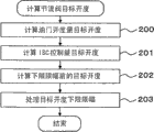
The target aperture (step 200) of calculation of throttle aperture amount then utilizes the processing of Fig. 3 to calculate racing speed controlled quentity controlled variable target apertures (step 201) in the drawings.Calculate the preceding target aperture (step 202) of lower limit amplitude limiting processing then.This calculating can be by realizing at the Calais accelerator open degree amount target aperture with racing speed controlled quentity controlled variable target aperture simply mutually.Then, carry out the lower limit amplitude limiting processing (step 203) of relevant target aperture of the present invention, finish.
Fig. 9 is the detail flowchart of the target aperture lower limit amplitude limiting processing (step 203) of Fig. 8.
Implement the condition criterion (step 300) of lower limit amplitude limiting processing in the drawings, then calculate the value (step 301) of lower limit amplitude limit.Target aperture and the lower limit amplitude limit value (step 302) before the lower limit amplitude limit relatively then, the target aperture before the lower limit amplitude limit be during greater than the lower limit amplitude limit value (when be "Yes"), with the target aperture (step 303) of the target aperture behind the amplitude limit before as amplitude limit, end.Target aperture before the lower limit amplitude limit as lower limit amplitude limit value (step 304), finishes the target aperture behind the amplitude limit during less than the lower limit amplitude limit value (when being "No").
Then the detail flowchart to the condition criterion (step 300) of the lower limit amplitude limiting processing of Fig. 9 is that Figure 10 describes.Calculate the variation (step 400) of target aperture, the then variation of comparison object aperture, with the pass of throttle valve opening be the predefined fixedly lower limit amplitude limit switching determination value of the relation of not dashing down, whether the variation of judging the target aperture less than the lower limit amplitude limit switching determination value (step 401) of fixing.During less than lower limit amplitude limit switching determination value, (when being "Yes") is provided with the mark (step 403) that the second lower limit amplitude limit is selected in permission, finishes in the variation of target aperture.Be worth when above (for "No" time) in the variation of target aperture in lower limit amplitude limit switching determination, remove the mark (step 402) that the second lower limit amplitude limit is selected in permission, finish.
Then the flow process that the lower limit amplitude limit value of Fig. 9 is calculated (step 301) is that Figure 11 describes.
In the drawings, judge and whether be provided with the permission mark (step 501) of selecting the second lower limit amplitude limit, be provided with the mark admissible of selecting the second lower limit amplitude limit clock (for "Yes" time), with the lower limit amplitude limit value as the second lower limit amplitude limit value (step 503) that is redefined for less than the first lower limit amplitude limit value, end process.
Clock (for "No" time) in that the mark admissible of selecting the second lower limit amplitude limit is not set, with the lower limit amplitude limit value as the first lower limit amplitude limit value (step 502) that is redefined for greater than the second lower limit amplitude limit value, end process.
By above processing, change under the little condition of not dashing down in the target throttle aperture, the lower limit amplitude limit value is made as little value, thereby can impact in mechanical full close position, can enlarge the control range of full close position side.
The following describes embodiments of the invention 2.
Judge condition that throttle valve opening can not dash down, be whether ISC closing control condition sets up (step 410).When setting up (when being "Yes"), the mark (step 412) that the second lower limit amplitude limit is selected in permission is set, finish.(when being "No") removes the mark (step 411) that the second lower limit amplitude limit is selected in permission when being false, and finishes.
The following describes embodiments of the invention 3.
Target aperture and the throttle valve opening predefined regulation aperture for the scope of dashing under the not meeting is compared, judge that whether the target aperture is less than regulation aperture (step 420).During aperture (when be "Yes"), the mark (step 422) that the second lower limit amplitude limit is selected in permission is set less than regulation in the target aperture, end.When the regulation aperture is above (when being "No"), remove the mark (step 421) that the second lower limit amplitude limit is selected in permission in the target aperture, finish.
The following describes embodiments of the invention 4.
Embodiment 4 relates to condition criterion (step 300) method of lower limit amplitude limiting processing of Fig. 8 of embodiment 1.According to Figure 14 its flow process is described.
Engine speed and the throttle valve opening predefined regulation rotating speed for the scope of dashing under the not meeting is compared, judge that whether engine speed is less than regulation rotating speed (step 430).During rotating speed (when be "Yes"), the mark (step 432) that the second lower limit amplitude limit is selected in permission is set less than regulation in engine speed, end.When the regulation rotating speed is above (when being "No"), remove the mark (step 431) that the second lower limit amplitude limit is selected in permission in engine speed, finish.
Engine loading height in the lower limit amplitude limiting processing condition criterion in above embodiment 1~4 is when illustrating beyond the speed change lever that there is no need throttle valve opening is diminished is N or P zone by Figure 15, with the method for lower limit amplitude limit as the first lower limit amplitude limit value.
Judge whether ISC closing control condition sets up (step 440).(when being "No") removes the mark (step 441) that the second lower limit amplitude limit is selected in permission when being false, and finishes.
When ISC closing control condition is set up (when being "Yes"), judge whether the state representation N of speed change lever or the neutral switch 17 beyond the P close (step 443), (when being "Yes") removes the mark (step 441) that the second lower limit amplitude limit is selected in permission when closing, and finishes.
If for opening (when being "No"), the mark (step 442) that the second lower limit amplitude limit is selected in permission is set, finishes.
As above-mentioned such engine loading height, there is no need condition that throttle valve opening is diminished, replace neutral switch 17 to close, also can be when air-conditioning switch 18 be opened or auxiliary load be that specified value is judged when above.
And,, do not judge when can finish or when detecting airflow control unusual in the study of the mechanical position limitation position of throttle valve 40 as the condition that there is no need throttle valve opening is diminished yet.
Above-mentioned having enumerated by removing permission selects the mark of the second lower limit amplitude limit to reach the example of the first lower limit amplitude limit value, but replaces the first lower limit amplitude limit value, also can use the 3rd lower limit amplitude limit value (not shown) greater than the first lower limit amplitude limit value.
The 3rd lower limit amplitude limit value is considered: the deviation that (a) detects the sensor of throttle valve; (b) deviation of the installation of throttle valve; (c) degree more than needed of the installation deviation of throttle valve; (d) at least one in the default location of throttle valve by being made as predefined value, can avoid comprising the conflict of the throttle valve of machine error, deviation.
In addition, in embodiment 1~4, when lower limit amplitude limiting processing condition repeats at short notice to set up and is false, do not carry out rapid variation, utilize Figure 16 to illustrate in situation through the permission second lower limit amplitude limit after the stipulated time in order to make the second lower limit amplitude limit value.
Judge whether ISC closing control condition sets up (step 450).(when being "No") removes the mark (step 451) that the second lower limit amplitude limit is selected in permission when being false, and finishes.
When ISC closing control condition is set up (when being "Yes"), judge whether passed through the stipulated time (step 453), if be "No", remove the mark (step 451) that the second lower limit amplitude limit is selected in permission, finish, if be "Yes", the mark (step 452) that the second lower limit amplitude limit is selected in permission is set, finish.
Replace above-mentionedly judging whether passed through the stipulated time like that, the second lower limit amplitude limit value is descended with the decrement of regulation, prevent the rapid change of the second lower limit amplitude limit value.
Below, utilize Figure 17 to illustrate that employing calculates the result's of the second lower limit amplitude limit method according to coolant water temperature.
Computational methods as the lower limit amplitude limit value, judge and whether be provided with the mark (step 521) that the second lower limit amplitude limit is selected in permission, be provided with the mark admissible of selecting the second lower limit amplitude limit clock (for "Yes" time), read coolant water temperature (step 523), determine the second lower limit amplitude limit value corresponding to water temperature with reference to the predefined second lower limit amplitude limit water-thermometer, make it when the load height of motor and coolant water temperature are low, become big, diminish when low and coolant water temperature is high at engine loading (step 524).Then the lower limit amplitude limit value is set at the second lower limit amplitude limit value (step 525), end process.
Clock (when being "No") at the mark admissible that the selection second lower limit amplitude limit is not set, the lower limit amplitude limit value is set at the first lower limit amplitude limit value (step 522), end process.
Below, utilize Figure 18,19 explanations to calculate the method for the second lower limit amplitude limit according to coolant water temperature and inhalation temperature.
The relation of lower limit amplitude limit, coolant water temperature and inhalation temperature at first, is described by Figure 18.Because the constituent part of throttle valve 40 is linear expansion coeffcient poor of valve 1000 and main body 1001, when low temperature and during high temperature, gap each other changes.The aperture that this means throttle valve till interfering changes, and in illustrated example, high temperature side can reduce the aperture of lower limit amplitude limit, can strengthen the aperture of lower limit amplitude limit during low temperature.Also have, the temperature of valve 1000 exists with ... the temperature of air flue, and the temperature of main body 1001 exists with ... the peripheral temperature of throttle valve 40 significantly.Herein, the peripheral temperature of throttle valve is owing to join with engine cooling water, and therefore relevant with coolant water temperature, the temperature of air flue is relevant with inhalation temperature.
As known from the above, than temperature when low, the lower limit amplitude limit value of coolant water temperature when high can be reduced, than the motor inhalation temperature when high, the lower limit amplitude limit value of motor inhalation temperature when low can be further reduced.
Below according to Figure 19, the calculation process that calculates the second lower limit amplitude limit according to coolant water temperature and inhalation temperature is described.
Computational methods as the lower limit amplitude limit value, judge that whether being provided with the second lower limit amplitude limit selects permission mark (step 531), if be provided with the permission mark (when being "Yes") of selecting the second lower limit amplitude limit, read coolant water temperature (step 533), read inhalation temperature (step 534), corresponding to coolant water temperature, inhalation temperature, coolant water temperature with reference to the predefined second lower limit amplitude limit, inhalation temperature figure, set the second lower limit amplitude limit value, make it when coolant water temperature is low, become big, when coolant water temperature is high, diminish, and when inhalation temperature is low, diminish, when air-breathing temperature is high, become big (step 536).But, because the influence of inhalation temperature also exists with ... the suction air quantity, so also can add the correction that sucks air quantity.Then the lower limit amplitude limit value is set at the second lower limit amplitude limit value (step 525), end process.
Clock (when being "No") at the mark admissible that the selection second lower limit amplitude limit is not set, the lower limit amplitude limit value is set at the first lower limit amplitude limit value (step 532), end process.
As mentioned above, according to the present invention, the following condition of dashing under being not easy to take place, for example when the throttle valve slow motion, during idling conditions, when throttle valve is not almost opened, when engine speed is low, by reducing the lower limit amplitude limit of target aperture, can avoid dashing down cause conflict in, throttle valve opening is not subjected to the restriction of lower limit amplitude limit and realizes control.
Also have, when the load of motor is in the state that is not easy to descend, for example, in the zone of speed change lever be beyond the P that applies of the load of torque control or the N time, when opening air-conditioning, when auxiliary load such as electrical load is arranged, because the necessity that improves motor output is arranged, so, can realize avoiding down dashing the control of the conflict that causes by not reducing the lower limit amplitude limit of target aperture.
Also have, arrive at throttle valve before the study of full close position, or when airflow control unusual, because throttle valve has the possibility of conflicting in full close position, so, can realize avoiding the control of the conflict that throttle valve control causes by not reducing or improve the lower limit amplitude limit.
For said apparatus, through after the stipulated time, reduce the lower limit amplitude limit of the target aperture of throttle valve after further setting up by the beginning condition of said apparatus, can replenish the retardation of actual aperture according to the target throttle valve opening.
In addition, the computational methods of the amplitude limit value when reducing the lower limit amplitude limit can be by calculating corresponding to coolant water temperature, inhalation temperature, revises the poor of full close position that the throttle valve thermal expansion causes.
Claims (10)
1. the airflow control of an internal-combustion engine is characterized in that, possesses:
By electric motor driven throttle valve;
Obtain the device of the target aperture and the target aperture pace of change of described throttle valve according to the operating condition of vehicle or internal-combustion engine; And
Setting device, it has as the first lower limit amplitude limit value lower limit of described target aperture, predefined, and when described target aperture pace of change of trying to achieve is lower than predefined value, sets second amplitude limit value less than the described first lower limit amplitude limit value.
2. the airflow control of internal-combustion engine as claimed in claim 1 is characterized in that,
Have described target aperture of trying to achieve and the described first lower limit amplitude limit value compares and in described target aperture during greater than the described first lower limit amplitude limit value, the device that described target aperture is set as the final objective aperture.
3. the airflow control of internal-combustion engine as claimed in claim 1 is characterized in that,
Have described target aperture of trying to achieve and the described first lower limit amplitude limit value compares and in described target aperture during less than the described first lower limit amplitude limit value, the device that described lower limit amplitude limit value is set as the final objective aperture.
4. the airflow control of internal-combustion engine as claimed in claim 2 is characterized in that,
Throttle valve opening and the consistent device of described final objective aperture that sensor with the aperture that detects described throttle valve and feedback control go out to the controlled quentity controlled variable of described motor so that by described sensor.
5. the airflow control of internal-combustion engine as claimed in claim 1 is characterized in that,
Be provided with when ISC closing control condition is set up, described lower limit amplitude limit be set at the device of the second lower limit amplitude limit value that is lower than the first lower limit amplitude limit value.
6. the airflow control of internal-combustion engine as claimed in claim 1 is characterized in that,
Have spacing position learning device, it is lower than the study of mechanical position limitation position of second amplitude limit of described throttle valve,
When the study of described spacing position learning device does not finish,, also set the described first lower limit amplitude limit value or greater than the 3rd lower limit amplitude limit of the described first lower limit amplitude limit value even setting under the condition of the described second lower limit amplitude limit value.
7. the airflow control of internal-combustion engine as claimed in claim 1 is characterized in that,
Has the unusual abnormal detecting device that detects airflow control, detecting when unusual by described abnormal detecting device or detecting when unusual, even setting under the condition of the described second lower limit amplitude limit value, also set the described first lower limit amplitude limit value or greater than the 3rd lower limit amplitude limit of the described first lower limit amplitude limit value.
8. the airflow control of internal-combustion engine as claimed in claim 1 is characterized in that,
Than coolant water temperature or inhalation temperature when high, when coolant water temperature or inhalation temperature are low, reduce the described second lower limit amplitude limit value.
9. the airflow control of internal-combustion engine as claimed in claim 1 is characterized in that,
Than throttle valve opening when big, hour determine described predefined value at throttle valve opening biglyyer.
10. the airflow control of internal-combustion engine as claimed in claim 1 is characterized in that,
Than throttle valve opening hour, when throttle valve opening is big, determine the described predefined stipulated time more longways.
Applications Claiming Priority (3)
| Application Number | Priority Date | Filing Date | Title |
|---|---|---|---|
| JP2006335229A JP4315192B2 (en) | 2006-12-13 | 2006-12-13 | Throttle valve control device for internal combustion engine |
| JP2006335229 | 2006-12-13 | ||
| JP2006-335229 | 2006-12-13 |
Publications (2)
| Publication Number | Publication Date |
|---|---|
| CN101201023A CN101201023A (en) | 2008-06-18 |
| CN101201023B true CN101201023B (en) | 2010-06-09 |
Family
ID=39084745
Family Applications (1)
| Application Number | Title | Priority Date | Filing Date |
|---|---|---|---|
| CN2007101620834A Active CN101201023B (en) | 2006-12-13 | 2007-12-04 | Throttle valve controller for internal combustion engine |
Country Status (4)
| Country | Link |
|---|---|
| US (2) | US8033266B2 (en) |
| EP (1) | EP1933019B1 (en) |
| JP (1) | JP4315192B2 (en) |
| CN (1) | CN101201023B (en) |
Families Citing this family (8)
| Publication number | Priority date | Publication date | Assignee | Title |
|---|---|---|---|---|
| DE102007053085A1 (en) * | 2007-11-07 | 2009-05-14 | Robert Bosch Gmbh | Method for stabilizing a regulator and corresponding regulator device |
| US8869523B2 (en) * | 2011-04-14 | 2014-10-28 | Caterpillar Inc. | Control system having variable-speed engine-drive fan |
| CN104234841B (en) * | 2013-06-17 | 2017-01-25 | 广州汽车集团股份有限公司 | Automotive electronic throttle valve control method and device |
| JP5583258B1 (en) * | 2013-09-26 | 2014-09-03 | 三菱電機株式会社 | Throttle learning control device |
| JP6183304B2 (en) * | 2014-07-01 | 2017-08-23 | トヨタ自動車株式会社 | Vehicle control device |
| JP6299566B2 (en) * | 2014-11-20 | 2018-03-28 | 株式会社デンソー | Valve device |
| JP6328201B2 (en) * | 2016-10-05 | 2018-05-23 | 三菱電機株式会社 | Control device for internal combustion engine |
| CN109854396B (en) * | 2019-01-31 | 2022-03-25 | 一汽解放汽车有限公司 | Soft seating control method of electronic control throttle valve |
Citations (1)
| Publication number | Priority date | Publication date | Assignee | Title |
|---|---|---|---|---|
| DE3328277A1 (en) * | 1983-08-05 | 1985-02-21 | Peter Dipl.-Phys. 7906 Blaustein Heumüller | Automatic choke with electronic idling speed control for a spark ignition engine carburettor with main throttle and choke valve |
Family Cites Families (21)
| Publication number | Priority date | Publication date | Assignee | Title |
|---|---|---|---|---|
| JPS5862334A (en) * | 1981-10-09 | 1983-04-13 | Mazda Motor Corp | Control device of idling revolution in engine |
| JP2606824B2 (en) * | 1986-06-06 | 1997-05-07 | 本田技研工業株式会社 | Throttle valve control system for vehicle internal combustion engine |
| US4791902A (en) * | 1986-07-16 | 1988-12-20 | Honda Giken Kogyo Kabushiki Kaisha | Throttle valve control system for an internal combustion engine |
| US4781162A (en) * | 1986-08-04 | 1988-11-01 | Honda Giken Kogyo Kabushiki Kaisha | Throttle valve control system for an internal combustion engine |
| US4787353A (en) * | 1986-09-24 | 1988-11-29 | Honda Giken Kogyo Kabushiki Kaisha | Throttle valve control apparatus for an internal combustion engine mounted on a vehicle |
| JP2519960B2 (en) * | 1987-12-28 | 1996-07-31 | いすゞ自動車株式会社 | Vehicle traction control method |
| JPH0625545B2 (en) * | 1987-12-28 | 1994-04-06 | 株式会社日立製作所 | Electronic throttle control device for internal combustion engine |
| DE3924582C2 (en) * | 1988-07-25 | 1995-02-09 | Nissan Motor | Throttle valve control device for wheel slip suppression in motor vehicles |
| JP3218373B2 (en) * | 1991-11-07 | 2001-10-15 | 株式会社ユニシアジェックス | Shift control device of automatic transmission for automobile |
| DE69325044T2 (en) * | 1992-02-19 | 1999-09-30 | Honda Motor Co Ltd | Machine cooling system |
| JP3531224B2 (en) | 1994-09-05 | 2004-05-24 | 日産自動車株式会社 | Engine throttle control |
| DE69834766T2 (en) * | 1997-05-26 | 2006-10-19 | Nissan Motor Co., Ltd., Yokohama | Idle speed controller for internal combustion engine |
| JP3579398B2 (en) * | 2002-01-25 | 2004-10-20 | 三菱電機株式会社 | Positioning control device |
| JP3872743B2 (en) * | 2002-03-28 | 2007-01-24 | 株式会社日立製作所 | Throttle valve opening / closing device |
| JP4110910B2 (en) * | 2002-10-03 | 2008-07-02 | トヨタ自動車株式会社 | Throttle opening control device for internal combustion engine |
| JP4268839B2 (en) * | 2003-06-26 | 2009-05-27 | 株式会社日立製作所 | Variable valve controller for internal combustion engine |
| US7150263B2 (en) * | 2003-12-26 | 2006-12-19 | Yamaha Hatsudoki Kabushiki Kaisha | Engine speed control apparatus; engine system, vehicle and engine generator each having the engine speed control apparatus; and engine speed control method |
| JP4391275B2 (en) * | 2004-03-09 | 2009-12-24 | 三菱電機株式会社 | Multi-cylinder engine operation control device |
| JP4020899B2 (en) * | 2004-08-31 | 2007-12-12 | 三菱電機株式会社 | Electronic throttle control device |
| JP4703170B2 (en) * | 2004-11-16 | 2011-06-15 | トヨタ自動車株式会社 | Control device for internal combustion engine |
| WO2006076407A1 (en) * | 2005-01-11 | 2006-07-20 | Berman Adam R | Control system combining a continuously variable transmission or an infinitely variable transmission and an electronic throttle control |
-
2006
- 2006-12-13 JP JP2006335229A patent/JP4315192B2/en active Active
-
2007
- 2007-11-27 US US11/945,657 patent/US8033266B2/en active Active
- 2007-12-04 EP EP07023452.1A patent/EP1933019B1/en active Active
- 2007-12-04 CN CN2007101620834A patent/CN101201023B/en active Active
-
2011
- 2011-08-31 US US13/222,051 patent/US8181628B2/en active Active
Patent Citations (1)
| Publication number | Priority date | Publication date | Assignee | Title |
|---|---|---|---|---|
| DE3328277A1 (en) * | 1983-08-05 | 1985-02-21 | Peter Dipl.-Phys. 7906 Blaustein Heumüller | Automatic choke with electronic idling speed control for a spark ignition engine carburettor with main throttle and choke valve |
Also Published As
| Publication number | Publication date |
|---|---|
| EP1933019A2 (en) | 2008-06-18 |
| US20110308496A1 (en) | 2011-12-22 |
| CN101201023A (en) | 2008-06-18 |
| JP4315192B2 (en) | 2009-08-19 |
| US20080141976A1 (en) | 2008-06-19 |
| JP2008144719A (en) | 2008-06-26 |
| US8033266B2 (en) | 2011-10-11 |
| EP1933019B1 (en) | 2017-03-08 |
| US8181628B2 (en) | 2012-05-22 |
| EP1933019A3 (en) | 2014-12-03 |
Similar Documents
| Publication | Publication Date | Title |
|---|---|---|
| CN101201023B (en) | Throttle valve controller for internal combustion engine | |
| KR940010730B1 (en) | Fail-safe system for vehicle engine | |
| CN108463620B (en) | Control method and control device for exhaust gas bypass valve | |
| JPH05222990A (en) | Idling control device for engine with suction and exhaust valve stop mechanism | |
| CN104420982A (en) | Determination of waste gate valve position | |
| JP2006194143A (en) | Control device for engine | |
| CN108223169B (en) | Vehicle control device | |
| JP4117472B2 (en) | EGR device | |
| JP2008297946A (en) | Control device for internal combustion engine | |
| CN109838323B (en) | Valve control method, valve control device and vehicle | |
| JP2008190430A (en) | Vehicle speed sensor failure diagnosis device for vehicle and cooling fan motor failure diagnosis device | |
| JP2002250252A (en) | Egr valve control device | |
| CN105569852A (en) | Method and apparatus for monitoring a coolant system for an exhaust gas recirculation system | |
| JP2014225142A (en) | Fault diagnosis apparatus | |
| KR101672040B1 (en) | Apparatus and method for controlling required torgue of vehicle | |
| JP4671716B2 (en) | Operation control method for internal combustion engine | |
| US20190383227A1 (en) | Method and device for controlling an internal combustion engine supercharged by an exhaust-gas turbocharger | |
| JP2004124798A (en) | Control device for internal combustion engine | |
| KR0166617B1 (en) | Intake air flow control method in idle of internal combustion engine | |
| KR100337340B1 (en) | Method for engine controlling of vehicle | |
| JP2018009512A (en) | On-vehicle control device | |
| JP2000179363A (en) | Fuel injection control device for electronically controlled throttle valve in abnormal state | |
| JP6243760B2 (en) | Throttle valve control device for internal combustion engine | |
| JP2008286055A (en) | Control device for actuator | |
| JP2009156218A (en) | Intake system malfunction detecting device |
Legal Events
| Date | Code | Title | Description |
|---|---|---|---|
| C06 | Publication | ||
| PB01 | Publication | ||
| C10 | Entry into substantive examination | ||
| SE01 | Entry into force of request for substantive examination | ||
| C14 | Grant of patent or utility model | ||
| GR01 | Patent grant | ||
| CP01 | Change in the name or title of a patent holder |
Address after: Hitachinaka County, Japan Patentee after: Hitachi astemo Co.,Ltd. Address before: Hitachinaka County, Japan Patentee before: HITACHI AUTOMOTIVE SYSTEMS, Ltd. |
|
| CP01 | Change in the name or title of a patent holder | ||
| TR01 | Transfer of patent right |
Effective date of registration: 20211130 Address after: Hitachinaka County, Japan Patentee after: HITACHI AUTOMOTIVE SYSTEMS, Ltd. Address before: Tokyo, Japan Patentee before: Hitachi, Ltd. |
|
| TR01 | Transfer of patent right |