CN101183048A - Digital control lathes error automatic sizing device - Google Patents
Digital control lathes error automatic sizing device Download PDFInfo
- Publication number
- CN101183048A CN101183048A CNA2007101687232A CN200710168723A CN101183048A CN 101183048 A CN101183048 A CN 101183048A CN A2007101687232 A CNA2007101687232 A CN A2007101687232A CN 200710168723 A CN200710168723 A CN 200710168723A CN 101183048 A CN101183048 A CN 101183048A
- Authority
- CN
- China
- Prior art keywords
- error
- module
- digital control
- error information
- data
- Prior art date
- Legal status (The legal status is an assumption and is not a legal conclusion. Google has not performed a legal analysis and makes no representation as to the accuracy of the status listed.)
- Granted
Links
Images


Landscapes
- Length Measuring Devices With Unspecified Measuring Means (AREA)
- Automatic Control Of Machine Tools (AREA)
Abstract
The invention provides an automatic error measuring device for a digital controlled lathe and comprises a lever-type inductance position finder, a step gauge, a clamp, a clamping mechanism as well as a data collection and process device. The measuring joint of the lever-type inductance position finder is contacted with the measuring datum plane of the step gauge; the clamping end of the lever-type inductance position finder is connected with the clamping end of the clamping mechanism; the lever-type inductance position finder is connected with the data collection and process device to transmit a displacement signal to the data collection and process device; the step gauge is arranged on the clamp. The invention improves the error measuring efficiency of the digital controlled lathe and reduces the complexity of error measuring operation and the error measuring cost.
Description
Technical field
The present invention relates to the monitoring field of logarithm car controlling bed operating state, especially relate to numerically controlled lathe error measure, evaluation and compensation field.
Technical background
Numerically controlled lathe is widely used in machine-building as machine-tool of new generation, and developing rapidly of precision processing technology and improving constantly of part processing precision are also had higher requirement to the precision of numerically controlled lathe.Bearing accuracy is an important indicator of numerically-controlled machine, and numerically controlled lathe manufacturer all needs its positional precision is demarcated when lathe dispatches from the factory; Simultaneously, the user often also very values the bearing accuracy, particularly bearing accuracy of each and repetitive positioning accuracy of lathe when choosing numerically-controlled machine.Statistical data shows: the new machine more than 65.7% does not all meet its technical indicator during installation; Numerically-controlled machine in 90% use is in the misalignment duty.Therefore, machine tool accuracy is carried out routine test be very important,, improve part processing precision so that in time find and deal with problems.
At present, existing commercial numerically-controlled machine all has the The compensation of pitch error function.Usually when numerically-controlled machine dispatches from the factory, need proofread and correct installation fully to it, manual input The compensation of pitch error data, this mode is easily made mistakes.The lathe user in use for some time, precision can continuous cracking, is necessary lathe is proofreaied and correct again.Current, error-detecting, evaluation and compensation are rings important in the dynamo-electric uniting and adjustment work, and it is one of reason of restriction lathe production in enormous quantities.Therefore, seek a kind of error calibration device simply, fast and cheaply, particularly necessary, particularly in a large amount of production and consumptions, low-grade low-cost type CNC lathe, have important practical significance.
And existing numerically-controlled machine error measurement method mainly contains the laser interferometer method, step gage and clock gauge combined method and grating chi method, there is certain limitation in these methods, wherein laser interferometer method complicated operation, efficient is low, cost is high and environment for use requires high; Step gage and clock gauge combined method, important problem wherein, most of need of work people's participation needs the people to read and handles as data, improves the possibility of makeing mistakes so greatly, and efficient is very low; The grating chi is installed inconvenience, and existing similar measuring system is not considered error compensation, as Heidenhain (Heidenhain) linear grating error measuring system.At present, laser interferometer is mainly adopted in the lathe error measure, and there is the cost height in laser interferometer, efficiency of measurement is low and shortcoming such as inconvenient operation.From having patent now: application number is 200510035936, the technical scheme that invention and created name is announced for the patent application document of " three-dimensional error compensation system and method " is: utilize the contour precision measure instrument of laser interferometer to measure the error of three-dimensional lathe, set up error model, utilize independently error module, coordinate figure according to input, by the error model error of calculation, the actual coordinate value after the output compensation.Because need manual input coordinate value, so its compensation is inconvenient.Application number is 200410093428.1, invention and created name is that the compensator that the patent application document of " based on the numerically-controlled machine real time error compensator of lathe exterior coordinate system biasing " is announced need be connected with the bottom hardware of digital control system when compensation, simultaneously when output offset error in real time, need be synchronous with the motion control of digital control system, therefore use inconvenient.Application number is 92204762.6, and the error cubing that invention and created name is announced for the patent application document of " T type machine tool error cubing " is very complicated in the process of installing and measuring, and also is not easy to use on the car machine.
Summary of the invention
The objective of the invention is to improve the efficient of numerically controlled lathe error measure, reduce the error measure cost.
A kind of digital control lathes error automatic sizing device comprises lever inductance direction finder, step gage, anchor clamps, clamping device and data acquisition and processor; The gauge head of lever inductance direction finder contacts with the measuring basis face of step gage, and the bare terminal end of lever inductance direction finder is connected with the bare terminal end of clamping device; Lever inductance direction finder is connected with processor with data acquisition, is used for to data acquisition and processor transmission displacement signal; Step gage is placed on the anchor clamps.
Described anchor clamps have a bottom surface and intersect vertically with the bottom surface and exceed the front of bottom surface, and respectively there is a side that exceeds the bottom surface at the two ends, bottom surface, and each is connected the outside of two sides with a pole, and the axis of two poles is parallel with the intersecting lens in front with the bottom surface.Described bottom surface upper ends has magnet.
Described anchor clamps have a bottom surface and intersect vertically with the bottom surface and exceed the front of bottom surface, one side of lower end, bottom surface has the surface level that is used for the inclined-plane that joins with the machine tool guideway inclined-plane and is used for joining with machine tool guideway, and the intersecting lens of this inclined-plane and surface level is vertical with positive intersecting lens with the bottom surface.The inclined-plane and the surface level of upper end, described bottom surface, lower end, described bottom surface one side all are placed with magnet.
Described data acquisition and processor (4) comprising:
Parameter is provided with module and is used to be provided with supplemental characteristic;
The G code generation module is used to receive autoregressive parameter that the supplemental characteristic of module is set, and generates the numerically-controlled machine movement instruction.
The measurement mechanism correction module is used to receive autoregressive parameter that supplemental characteristic, the displacement signal from lever inductance direction finder, the actual displacement of the manual lever inductance direction finder of importing and the actual pitch between the step gage point position of module are set, calculate the measurement mechanism error information, send it to error measure module;
The error measure module be used to receive autoregressive parameter the supplemental characteristic of module is set, from the displacement signal of lever inductance direction finder with from the measurement mechanism error information of measurement mechanism correction module, obtain displacement data according to displacement signal, judge lathe fortune, stop state, utilize measurement mechanism error information correction displacement data, revised displacement data is handled the formation error information, send error information to the data splicing module;
The data splicing module is used to receive autoregressive parameter that the supplemental characteristic of module is set and from the error information of error measure module, generates the error information of whole machine tool motion stroke.
Described data acquisition and processor also comprise the error compensation module, and it is used to receive autoregressive parameter that the supplemental characteristic of module is set and from the error information of data splicing module, error information are handled generating corresponding error compensation data.
Described data acquisition and processor also comprise the precision evaluation module, and it is used to receive autoregressive parameter that the supplemental characteristic of module and the error information of error concatenation module are set, and according to predetermined evaluation criterion error information is analyzed and is handled, and obtains evaluation result.
Described clamping device is the magnetic force gauge stand.
The anchor clamps of the present invention's design utilize locating surface to locate, guarantee the position relation of measurement mechanism and measured axis, improve efficiency of measurement greatly, in anchor clamps, inlayed simultaneously magnet, make step gage closely contact with anchor clamps, do not need other clamping structure, simplified installation process, reduced the non-cutting time of measuring; There are foozle and the non-linear error that causes at measurement mechanism itself, after using simultaneously, the cracking of precision may appear, designed the measurement mechanism correction module, the error input system at diverse location of relevant apparatus, in the measuring process afterwards, system can revise automatically because the error that the measurement mechanism error causes improves measuring accuracy; The present invention can be used to measure the error of big stroke lathe, and promptly the step gage of shorter length also can be measured the lathe of big stroke, has reduced the cost of measurement mechanism like this.Data acquisition and processor generate G code automatically and handle measurement data automatically and generate the compensation file, send it to CNC, realize error compensation fast, by processing, can obtain required precision index of user and error profile fast simultaneously error information.
Description of drawings
Fig. 1 is a structural drawing of the present invention;
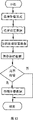
Fig. 2 is data acquisition of the present invention and processor structure figure;
Fig. 3 is relay measuring principle figure of the present invention;
Fig. 4 is step gage and the anchor clamps synoptic diagram of the present invention when measuring lathe Z axle;
Step gage and anchor clamps synoptic diagram when Fig. 5 is a measured X axle of the present invention;
Fig. 6 is that parameter of the present invention is provided with process flow diagram;
Fig. 7 is G code product process figure of the present invention;
Fig. 8 is measurement mechanism correcting process figure of the present invention;
Fig. 9 is an error measure process flow diagram of the present invention;
Figure 10 is a data splicing process flow diagram of the present invention;
Figure 11 is a precision evaluation process flow diagram of the present invention;
Figure 12 is an error compensation process flow diagram of the present invention.
Embodiment
The present invention is mainly used on the lathe.Fig. 1 is a structural drawing of the present invention, and this system comprises step gage 5, anchor clamps 9, lever inductance direction finder 3, clamping device 8 and data acquisition and processor 4.Wherein, the bare terminal end of lever inductance direction finder 3 is connected with the bare terminal end of clamping device 8, and the gauge head of lever inductance direction finder 3 contacts with the measuring basis face of step gage 5.Lever inductance direction finder 3 is connected with processor 4 with data acquisition, is used for to data acquisition and processor 4 transmission displacement signals.The error compensation data that data acquisition and processor 4 generate the G code file and obtain according to displacement signal automatically, and send CNC1 to.Step gage 5 is adsorbed on anchor clamps 9 tops, and clamping device 8 is adsorbed on the lathe saddle 6 away from an other end of bare terminal end.
The present invention adopts the combination of traditional step gage 5 and lever inductance direction finder 3 as measurement mechanism, and its measuring principle is the same with the measuring principle of step gage 5 and dial gauge combination.The material of high precision step gage is a marble now, and it has the precision height, and thermal expansivity is little, so the precision height.Lever inductance direction finder 3 selects range little, as 200um, its precision up to 1um about, and mechanical clock gauge precision reaches about 6um.The present invention adopts lever inductance type direction finder 3, is convenient to realize robotization, improves the convenience of efficiency of measurement and data processing.Clamping device 8 among the present invention adopts the magnetic force gauge stand.
When measuring lathe Z axle, anchor clamps 9 one ends are clipped on the chuck 2, and the other end is withstood by top 7 of lathe; When measuring the lathe X-axis, anchor clamps 9 are adsorbed on the Z axis rail 10 of lathe, by the locating surface location of guide rail.
As shown in Figure 2, data acquisition and processor 4 comprise seven modules: parameter is provided with module 41, G code generation module 42, measurement mechanism correction module 43, error measure module 44, data splicing module 45, precision evaluation module 46 and error compensation module 47.
Parameter is provided with module 41 and mainly finishes measuring the parameter setting relevant with compensation, comprise parameters such as digital control system type, measure dot number, spacing, measurement axis, time zero direction, generate supplemental characteristic, and provide supplemental characteristic to G code generation module 42, measurement mechanism correction module 43, error measure module 44, data splicing module 45, precision evaluation module 46 and error compensation module 47.
G code generation module 42 receives autoregressive parameter that the supplemental characteristic of module 41 is set, and parameters such as the measure dot number in the extracting parameter data, spacing, measurement axis, time zero direction, time out generate the numerically-controlled machine movement instruction, i.e. G code.
Measurement mechanism correction module 43 is used to calculate the measurement mechanism error information, sends it to error measure module 44.The measurement mechanism error information comprises lever inductance direction finder 3 directional error data and step gage 5 directional error data.The method of obtaining lever inductance direction finder 3 directional error data is: measurement mechanism correction module 43 is gathered the displacement signal of lever inductance direction finder 3, according to displacement signal picked up signal shift value; Manually import the actual displacement value of lever inductance direction finder 3 to measurement mechanism correction module 43, actual displacement value is corresponding with the signal shift value, actual displacement value is measured by high precision instruments such as laser interferometer, the scope of demarcating will cover whole measurement range, and this process preferably cooperates with lathe to be finished; Measurement mechanism correction module 43 calculates lever inductance direction finder 3 directional error data according to signal shift value and actual displacement value.The method of obtaining step gage 5 directional error data is: to the manual actual pitch values between the input step gage point positions of measurement mechanism correction module 43, the actual pitch value utilizes high precision instrumental calibration such as laser interferometer to obtain; Measurement mechanism correction module 43 according to the step gage in actual pitch and the supplemental characteristic count, spacing parameter calculates step gage 5 directional error data.
Error measure module 44 receives autoregressive parameter that the supplemental characteristic of module 41 is set, in the lathe operation, gather the displacement signal of lever inductance direction finder 3, obtain displacement data according to displacement signal, and according to displacement data judge lathe fortune, stop state, employing is from the directional error data correction displacement data of measurement mechanism correction module 43, revised displacement number is handled the formation error information, send error information to data splicing module 45.
Data splicing module 45 receives autoregressive parameter that the supplemental characteristic of module 41 is set; Processing is from the error information of error measure module 44, generates the error information of whole machine tool motion stroke according to the relay measuring principle, sends error information to precision evaluation module 46 and error compensation module 47.
Precision evaluation module 46, receive autoregressive parameter that the parameter of module 41 and the error information of error concatenation module 45 are set, according to predetermined evaluation criterion error information is analyzed and handled, obtain and export evaluation result, be backlass, bearing accuracy, repetitive positioning accuracy and error profile curve, for further analytical error source provides the basis.
Error compensation module 47, receive autoregressive parameter that the supplemental characteristic of module 41 is set and from the error information of data splicing module 45, according to digital control system type parameter in the supplemental characteristic and the two-way or unidirectional error compensation mode of employing error information is handled, generate corresponding error compensation data, send this to CNC1, cover error compensation data among the digital control system CNC1, realize error compensation.
The application that Fig. 3 measures for relay of the present invention is measured the error of putting in the range ability when measuring step gage all in the I position, and promptly machine tool position point B, C, D, E and F are with respect to the error of location point A, and then, mobile step gage 5 arrives II position, location point F point F
1Overlap (consider the machine tool error continuity, do not need strict the coincidence, promptly in certain error range, can satisfy measurement requirement), measure wherein machine tool position point G, H, I, J, K with respect to a F
1Error, the error of machine tool position point F when then putting G, H, I, J, K and adding in the I position respectively with respect to the error of the error of the A machine tool position point that to be step gage measure when the II position.
Fig. 4 is step gage and the anchor clamps synoptic diagram of the present invention when measuring lathe Z axle.When measuring the Z axis error,, anchor clamps 9 have been designed because step gage 5 can not clamping and is subjected to bigger power.Anchor clamps 9 have a bottom surface and intersect vertically with the bottom surface and exceed the front of bottom surface, and respectively there is a side that exceeds the bottom surface at the two ends, bottom surface, and each is connected the two sides outside surface with a pole that is used for clamping.The axis that guarantees two poles is parallel with positive intersecting lens with the bottom surface, makes the front become the locating surface of anchor clamps 9.One of them pole is by chuck 2 clampings, and another pole is withstood by top 7 of lathe tail end.Step gage 5 places on the anchor clamps 9, places magnet on the bottom surface, makes step gage 5 closely contact with anchor clamps 9.Certainly, because when measuring the Z axle, step gage 5 X to deflection little to measuring accuracy influence, as on the step gage 5 of 600mm, and its reference field and Z axle are not parallel, reference field near the position, rear and front end be in X to relative position during at 40um, and Z to measuring error have only 0.0013um, and the position relation that guarantees step gage 5 and Z axle in front the error range internal ratio of hypothesis be easier to.
Anchor clamps and step gage synoptic diagram when Fig. 5 is a measured X axle of the present invention, step gage 5 are adsorbed on the top, bottom surface of edge anchor clamps 9.Anchor clamps 9 have a bottom surface and intersect vertically with the bottom surface and exceed the front of bottom surface, and the lower end of bottom surface is useful on inclined-plane that contacts with machine tool guideway 10 inclined-plane faces and the surface level that is used for contacting with machine tool guideway upper surface face.The intersecting lens that guarantees this inclined-plane and surface level is vertical with positive intersecting lens with the bottom surface, makes the front become the locating surface of anchor clamps 9.The inclined-plane and the horizontal plane itself of its upper end, bottom surface, lower end, bottom surface one side are all placed magnet.The base of anchor clamps 9 contacts with 10 of lathe Z axis rails, because the base of anchor clamps 9 is magnetic, so the base of anchor clamps 9 closely contacts with guide rail, do not need clamping just can guarantee that the relative pose of anchor clamps 9 and lathe concerns in measuring process.In order to guarantee the position orientation relation of step gage 5 and X axis, in the time of on being installed in guide rail, the bottom surface of anchor clamps 9 is parallel with X axis with positive intersection.By the design of these anchor clamps 9, in measuring process, do not need measuring appliance is adjusted, directly can measure, reached the purpose that improves efficiency of measurement.
Fig. 6 is that parameter of the present invention is provided with process flow diagram, spacing, measurement axis, time parameters such as zero direction, cycle index and time out between digital control system type (selectable system comprises Central China numerical control, Guangzhou numerical control, Siemens, method clarke and Mazak etc.), measure dot number, the measurement point are set, wherein if need not generate G code, zero direction, cycle index and time out parameter need be set back, preserve supplemental characteristic, for other module provides supplemental characteristic.
Fig. 7 is that the present invention generates the G code process flow diagram automatically, receive autoregressive parameter that the supplemental characteristic that module 41 generates is set, extract wherein measure dot number, measurement spacing, time zero direction, parameters such as measurement cycle index, time out and measurement axis, automatically generate the G code file, cooperate with serial ports or the network communication program of CNC1, can directly be transferred to optional position among the CNC1 to this file.
Fig. 8 is measurement mechanism correcting process figure of the present invention.When demarcating step gage 5, parameter such as extract the spacing of step gage 5 and count, manual mode is imported the actual value by high precision instrumental calibrations such as laser interferometer of these corresponding step gage 5 positions, and system calculates step gage 5 directional error data when this position automatically; When demarcating lever inductance direction finder 3, system gathers the displacement signal of lever inductance direction finder automatically, obtain its signal shift value, use high precision instrument (as laser interferometer) to measure actual displacement value simultaneously, this is worth the Data Input Interface of manual input measurement device correction module 43.System calculates lever inductance direction finder 3 directional error data according to signal shift value and actual displacement value.
As shown in Figure 9, error measure process flow diagram of the present invention.In order to make software systems can be fit to the different measuring mode, software systems provide error information manual input interface, can accept from the machine tool error data that measure to obtain under other metering systems (as laser interferometer, grating chi) condition, for precision evaluation module 46 and error compensation module 47 provide error information.When metering system is step gage 5 modes, data acquisition and lathe need keep coordinating, promptly the error information and instruction position of Ce Lianging is corresponding, and do not have communication between error measure module 44 and the lathe, and to coordinate in order to realize data acquisition and lathe, system is by gathering the displacement signal of lever inductance direction finder 3, according to its variation, automatically judge the static or motion state of lathe, when machine tool motion arrived impact point, system write down the displacement data of lever inductance direction finder 3 automatically.Repeat this collection and deterministic process, when counting of collection reaches counting of parameter setting, employing is handled the generated error data from the directional error data correction displacement data of measurement mechanism correction module 43 to revised displacement data, and preserves error information.
Figure 10 is a data splicing process flow diagram of the present invention, the error information that selection is generated by error measure module 44, when measuring by relay, successively choose error information according to machine tool position, when splicing, also to splice in proper order, revise measure dot number and spacing parameter in the parameter, according to the principle deal with data of relay measurement by this, the final error information that obtains whole stroke is for modules 47 such as the precision evaluation 46 of back, error compensation provide data.
Figure 11 is a precision evaluation process flow diagram of the present invention, selected evaluation criterion, and evaluation criterion has iso standard, European standard, Nippon Standard and national standard, the standard difference, the algorithm of the processing of evaluation is also different.Then, the error information that Select Error concatenation module 45 obtains is handled error information according to selected standard, the output evaluation result, and the evaluation index of output has backlass, bearing accuracy and repetitive positioning accuracy.In addition, in order to understand error profile and error source better, export the repeated curve of backlass curve, graph of errors and error simultaneously.
Shown in Figure 12, error compensation process flow diagram of the present invention, the mode of Select Error compensation at first, the mode of error compensation has unidirectional and two-way.Choose the error information that data splicing module 45 generates then, according to parameter the supplemental characteristic that module 41 generates is set, error information is handled, generate the error compensation data of corresponding digital control system, cooperate with serial ports or the network communication program of CNC1, these data directly are transferred among the CNC1, cover the error compensation data in the digital control system, can realize error compensation fast.
Claims (9)
1. a digital control lathes error automatic sizing device comprises lever inductance direction finder (3), step gage (5), anchor clamps (9), clamping device (8) and data acquisition and processor (4); The gauge head of lever inductance direction finder (3) contacts with the measuring basis face of step gage (5), and the bare terminal end of lever inductance direction finder (3) is connected with the bare terminal end of clamping device (8); Lever inductance direction finder (3) is connected with processor (4) with data acquisition, is used for to data acquisition and processor (4) transmission displacement signal; Step gage (5) is placed on the anchor clamps (9).
2. digital control lathes error automatic sizing device according to claim 1, it is characterized in that, described anchor clamps (9) have a bottom surface and intersect vertically with the bottom surface and exceed the front of bottom surface, respectively there is a side that exceeds the bottom surface at the two ends, bottom surface, each is connected the outside of two sides with a pole, and the axis of two poles is parallel with positive intersecting lens with the bottom surface.
3. digital control lathes error automatic sizing device according to claim 2 is characterized in that, described bottom surface upper ends has magnet.
4. digital control lathes error automatic sizing device according to claim 1, it is characterized in that, described anchor clamps (9) have a bottom surface and intersect vertically with the bottom surface and exceed the front of bottom surface, one side of lower end, bottom surface has the surface level that is used for the inclined-plane that joins with the machine tool guideway inclined-plane and is used for joining with machine tool guideway, and the intersecting lens of this inclined-plane and surface level is vertical with positive intersecting lens with the bottom surface.
5. digital control lathes error automatic sizing device according to claim 4 is characterized in that, all is placed with magnet on the inclined-plane of upper end, described bottom surface, lower end, described bottom surface one side and the surface level.
6. digital control lathes error automatic sizing device according to claim 1 is characterized in that, described data acquisition and processor (4) comprising:
Parameter is provided with module (41) and is used to be provided with supplemental characteristic;
G code generation module (42) is used for receiving autoregressive parameter that the supplemental characteristic of module (41) is set, and generates the numerically-controlled machine movement instruction;
Measurement mechanism correction module (43) is used for receiving autoregressive parameter that supplemental characteristic, the displacement signal from lever inductance direction finder (3), the actual displacement of the manual lever inductance direction finder of importing (3) and the actual pitch between step gage (5) the some position of module (41) are set, calculate the measurement mechanism error information, send it to error measure module (44);
The supplemental characteristic that error measure module (44) is used for receiving autoregressive parameter that module (41) are set, from the displacement signal of lever inductance direction finder (3) with from the measurement mechanism error information of measurement mechanism correction module (43), obtain displacement data according to displacement signal, judge lathe fortune, stop state, utilize measurement mechanism error information correction displacement data, revised displacement data is handled the formation error information, send error information to data splicing module (45);
The supplemental characteristic that data splicing module (45) is used for receiving autoregressive parameter that module (41) is set and from the error information of error measure module (44) generates the error information of whole machine tool motion stroke.
7. digital control lathes error automatic sizing device according to claim 6, it is characterized in that, described data acquisition and processor (4) also comprise error compensation module (47), the supplemental characteristic that it is used for receiving autoregressive parameter that module (41) is set and from the error information of data splicing module (45) handles to generate corresponding error compensation data to error information.
8. according to claim 6 or 7 described digital control lathes error automatic sizing devices, it is characterized in that, described data acquisition and processor (4) also comprise precision evaluation module (46), it is used for receiving autoregressive parameter that the supplemental characteristic of module (41) and the error information of error concatenation module (45) are set, according to predetermined evaluation criterion error information is analyzed and handled, obtain evaluation result.
9. according to claim 6 or 7 described digital control lathes error automatic sizing devices, it is characterized in that described clamping device (8) is the magnetic force gauge stand.
Priority Applications (1)
| Application Number | Priority Date | Filing Date | Title |
|---|---|---|---|
| CN2007101687232A CN101183048B (en) | 2007-12-10 | 2007-12-10 | Digital control lathes error automatic measuring device |
Applications Claiming Priority (1)
| Application Number | Priority Date | Filing Date | Title |
|---|---|---|---|
| CN2007101687232A CN101183048B (en) | 2007-12-10 | 2007-12-10 | Digital control lathes error automatic measuring device |
Publications (2)
| Publication Number | Publication Date |
|---|---|
| CN101183048A true CN101183048A (en) | 2008-05-21 |
| CN101183048B CN101183048B (en) | 2010-06-30 |
Family
ID=39448400
Family Applications (1)
| Application Number | Title | Priority Date | Filing Date |
|---|---|---|---|
| CN2007101687232A Expired - Fee Related CN101183048B (en) | 2007-12-10 | 2007-12-10 | Digital control lathes error automatic measuring device |
Country Status (1)
| Country | Link |
|---|---|
| CN (1) | CN101183048B (en) |
Cited By (3)
| Publication number | Priority date | Publication date | Assignee | Title |
|---|---|---|---|---|
| CN103047959A (en) * | 2013-01-18 | 2013-04-17 | 北京理工大学 | Plane shape error evaluating method aiming at precise assembling and based on entropy theory |
| CN104483891A (en) * | 2014-10-29 | 2015-04-01 | 北京工研精机股份有限公司 | Method for improving machine tool space movement precision |
| CN112506131A (en) * | 2020-11-09 | 2021-03-16 | 襄阳华中科技大学先进制造工程研究院 | Method for selecting measuring point of numerical control machine tool |
Family Cites Families (1)
| Publication number | Priority date | Publication date | Assignee | Title |
|---|---|---|---|---|
| CN100462677C (en) * | 2005-07-08 | 2009-02-18 | 鸿富锦精密工业(深圳)有限公司 | Three-coordinate measuring machine-tool error compensation system and method |
-
2007
- 2007-12-10 CN CN2007101687232A patent/CN101183048B/en not_active Expired - Fee Related
Cited By (5)
| Publication number | Priority date | Publication date | Assignee | Title |
|---|---|---|---|---|
| CN103047959A (en) * | 2013-01-18 | 2013-04-17 | 北京理工大学 | Plane shape error evaluating method aiming at precise assembling and based on entropy theory |
| CN103047959B (en) * | 2013-01-18 | 2015-09-30 | 北京理工大学 | A kind of flat form error detection method based on entropy theory towards Fine Boring |
| CN104483891A (en) * | 2014-10-29 | 2015-04-01 | 北京工研精机股份有限公司 | Method for improving machine tool space movement precision |
| CN112506131A (en) * | 2020-11-09 | 2021-03-16 | 襄阳华中科技大学先进制造工程研究院 | Method for selecting measuring point of numerical control machine tool |
| CN112506131B (en) * | 2020-11-09 | 2023-02-28 | 襄阳华中科技大学先进制造工程研究院 | Method for selecting measuring point of numerical control machine tool |
Also Published As
| Publication number | Publication date |
|---|---|
| CN101183048B (en) | 2010-06-30 |
Similar Documents
| Publication | Publication Date | Title |
|---|---|---|
| CN101342664B (en) | On-machine quality detecting system for complex space type surface | |
| CN110530296A (en) | A kind of line laser fix error angle determines method | |
| CN101183048B (en) | Digital control lathes error automatic measuring device | |
| CN105698670A (en) | Machine tool guide rail installation plane parallelism quick measurement device and method | |
| CN112361957B (en) | Method for measuring and adjusting spatial position relationship of multiple positioners | |
| CN101183049B (en) | Nc milling machine error automatic sizing device | |
| CN104166373A (en) | Online detecting method and system for numerical control machine tool machining error | |
| CN202204481U (en) | Gear chamfering laser gauge | |
| CN102658503B (en) | Modal testing method of numerical control machine tool feed system based on built-in sensors | |
| CN101893457B (en) | High-precision full-parameter detection method for continuous motion | |
| CN102814707A (en) | Device and method for determining trigger stroke of trigger sensor | |
| CN102478824A (en) | Real-time error compensator for numerical control machine tool | |
| CN110057392A (en) | Calibration system for current vortex sensor | |
| CN102322819A (en) | Gear chamfer laser measuring instrument | |
| CN201149548Y (en) | Device for automatically measuring error of digital control lathes | |
| CN103273382A (en) | Reading device of grating ruler | |
| CN110977612B (en) | CNC (computer numerical control) machining online measurement error correction method and system | |
| CN205552535U (en) | Industrial robot laser orbit detection device | |
| CN201166611Y (en) | Apparatus for automatically measuring numerical control milling machine error | |
| CN210070852U (en) | Grating ruler service life tester | |
| CN103438816A (en) | High-precision measuring device for measuring joint type equipment member bar deformation | |
| CN101660895B (en) | Computer system and method for accurately positioning element to be measured | |
| CN105571482A (en) | Locking device of measuring guide rail linearity, and measuring device and method thereof | |
| CN100574088C (en) | The control method of mechanical absolute zero position in the stepper motor transmission system | |
| CN109483549A (en) | A kind of origin calibration system and method |
Legal Events
| Date | Code | Title | Description |
|---|---|---|---|
| C06 | Publication | ||
| PB01 | Publication | ||
| C10 | Entry into substantive examination | ||
| SE01 | Entry into force of request for substantive examination | ||
| C14 | Grant of patent or utility model | ||
| GR01 | Patent grant | ||
| C17 | Cessation of patent right | ||
| CF01 | Termination of patent right due to non-payment of annual fee |
Granted publication date: 20100630 Termination date: 20101210 |