Method and device for transmitting fiber channel service
Technical Field
The present invention relates to the field of optical communications, and in particular, to a method and an apparatus for transmitting fibre channel services.
Background
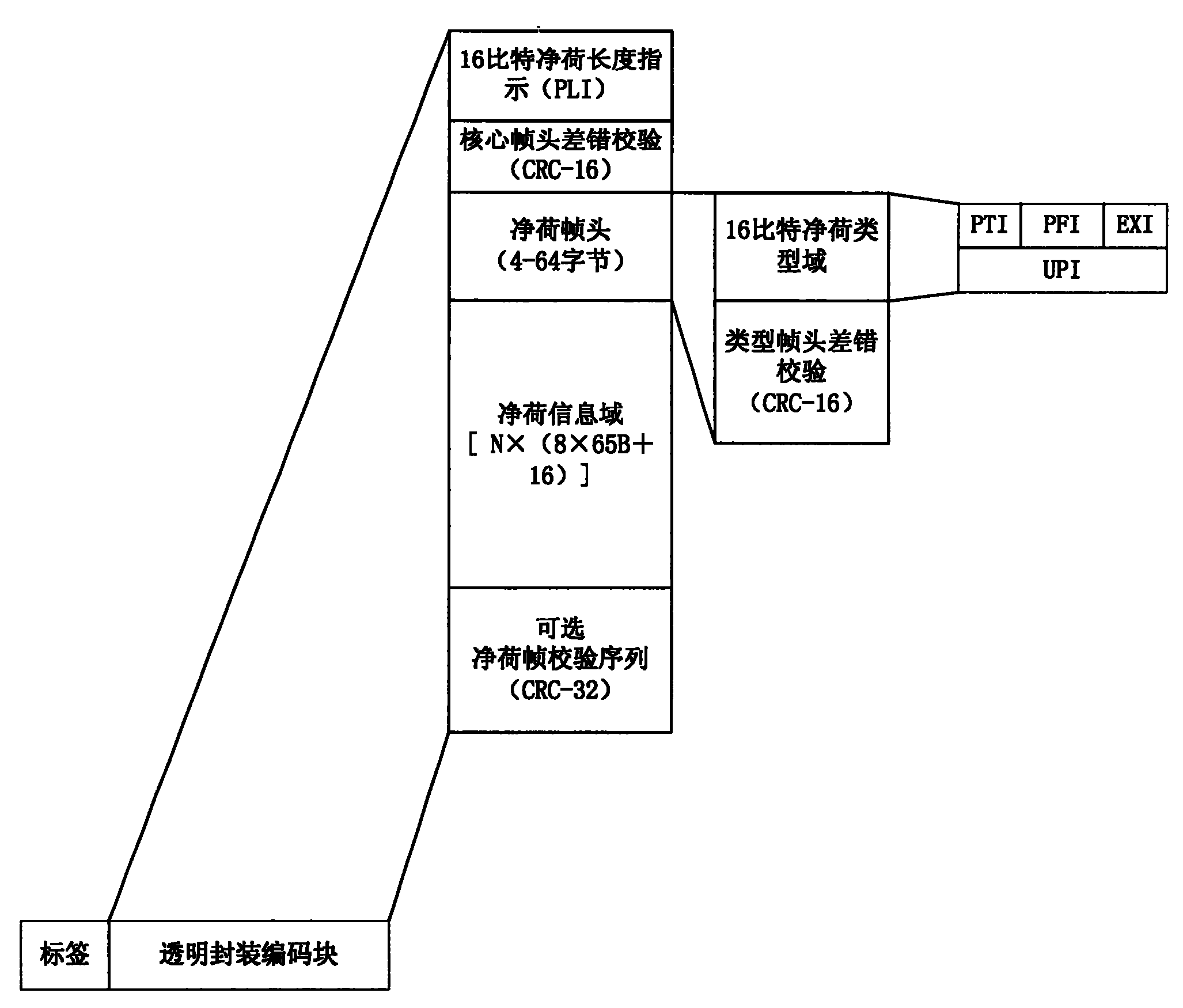
GFP (Generic Framing Procedure-Generic Framing Procedure) is an encapsulation adaptation technology that can encapsulate various data services, such as ethernet, MPLS (Multiple Protocol Label Switch), IP (Internet Protocol-Internet Protocol), FC (Fibre Channel-Fibre Channel), etc. The encapsulated GFP frame is mapped to a virtual container of SDH/OTN (Synchronous Digital Hierarchy/Optical transport network-Optical transport network), thereby realizing data service transport. There are two ways of encapsulating GFP: GFP-F (GFPFraming-GFP frame mode) and GFP-T (GFP delivery-GFP Transparent mode). For the GFP transparent transmission mode, the method can be suitable for 8B/10B coded two-layer data services, such as GE (Gigabit Ethernet-Gigabit Ethernet), FC (fiber channel) and the like, and can provide low-delay encapsulation based on byte encapsulation of physical coding. As shown in fig. 1, which is a structure diagram of a GFP frame, a GFP core frame header has 4 bytes, and includes a 16-bit Payload Length Indication (PLI) and a 16-bit core frame header error check; the GFP payload domain includes all bytes except GFP core frame head, and is used for transmitting high-level customer information, this area can be 4-65535 bytes lengthened, GFP payload domain has payload frame head and payload information field two parts, in addition, there is a payload frame check sequence of the optional domain, the header of the payload frame is the area that 4-64 bytes lengthen, finish the Data link management function correlated to customer signal, the payload information field can bear the PDU (Protocol Data Unit-Protocol Data Unit) adopting framing mapping or customer signal character adopting transparent mapping.
The FC interface is a standard interface for SAN (Storage Area Network). A SAN is a dedicated, high-speed data storage network that interconnects multiple independent storage systems with multiple servers using fibre channel switches and other switching devices. With the increase of data security requirements and data sharing requirements, a plurality of geographically separated SAN networks need to be connected to implement disaster recovery backup and data integration of data, so that an FC service interface needs to be accessed to a transport network to implement transparent transport. Although Transport networks have transitioned from the past SDH Platform that supports voice Transport to the multi-Service Transport MSTP (Multiple Service Transport Platform) -Platform due to the growth of data traffic, current MSTP is mainly based on an SDH processing Platform, as shown in fig. 2.
As shown in fig. 3, FC-BB-3_ GFPT over SDH implements GFP encapsulation of FC traffic and transport of FC traffic over SDH or OTN network. FC service accessed from FC equipment is processed by FC-0/FC-1 interface processing and FC-BB-3_ GFPT processing module on FC interface equipment, the two steps of processing mainly complete FC control protocol and GFP encapsulation, the FC control protocol comprises interface negotiation, far-end flow control processing and the like, FC-BB-3_ GFPT protocol state machine realizes FC interface connection initialization and connection establishment, FC protocol control frames such as ELP, FLOGI, PLOGI, SW _ ACC and LS _ ACC are monitored, and parameters meeting the requirement of entering a wide area network to transmit control frames are modified, so that the effective flow control capability of the FC service transmitted in the wide area network is realized. And after the FC-BB-3_ GFPT protocol state machine processing is finished, encapsulating the physical coding frame of the FC service into a GFP frame. At the GFPT processing unit, the FC physical coding frame, including data words and control words, is first encapsulated in every 8 bytes (64 bits total) according to the 64B/65B coding format. 8 65B modules are added with 16-bit FCS (Frame Check Sequence-Frame Check Sequence) Check to form a SuperBlock. N superblocks are packed into GFP frames as payload information fields to form GFPT packages, where the value of N depends on the base rate of the client signal and the capacity of the transmission channel. And finally, the GFP frame is mapped into an SDH virtual container, and the virtual cascade connection or cascade connection mode is adopted to realize the large-bandwidth service transmission. In the mapping to the SDH virtual container, the rate adaptation needs to be realized through a GFP idle frame, and the consistency of the rates of the GFP service frame and the SDH virtual container is met. The technology multiplexes the FC service to the SDH, and since the FC service is a data service with large bandwidth, the multiplexing to the SDH virtual container needs to adopt a complex virtual cascade technology, which will increase the difficulty of implementation. With the further development of service IP, the next generation of transport platform will be a multi-service transport platform based on packet technology, such as PBT (provider backbone transport), MPLS, etc., and with the development of packet transport network, the transport technology of SDH platform will gradually die.
As shown in fig. 4, FC over PWE3(Pseudo Wire Emulation Edge-to-Edge-end-to-end pseudowire Emulation) is transmitted over a packet network by PW encapsulating FC traffic. First, the accessed FC service is processed by an NSP (natural service Processing-local service Processing) module, for example, FC connection registration, FC near-end flow control response, FC far-end flow control Processing, and the like. Then, PW encapsulation is added to the FC-2 frame obtained after processing to form a PW service, the PW service is multiplexed to a transmission tunnel, and finally the PW service enters a Packet-Switched Network (PSN). According to the scheme, the FC service is subjected to PW encapsulation, FC physical layer control information consists of 8B/10B coded special characters, the PW encapsulation is completed to transparently transmit the FC-2 frame, but the FC physical coding information is terminated, so that the control information of the FC physical layer cannot be transparently transmitted. If the control information of the FC physical layer is to be transmitted transparently, the NSP module is required to perform special transcoding and identification on the control information, which greatly increases the complexity of the NSP processing module. In addition, the FC-2 frame is added with a PW label and an MPLS transport label so as to be multiplexed into the Ethernet frame for transmission. The frame length of FC-2 is 2148 bytes at most, because Ethernet proposes to transmit the maximum frame length of 1518 bytes, the PW packet for encapsulating FC service can not meet the requirement, and fragmentation operation is needed, i.e. the FC-2 frame is divided into two packets for transmission, thus further increasing the complexity of PW encapsulation processing.
Disclosure of Invention
In order to solve the problems that the optical fiber channel service is not suitable for being transmitted on an SDH network and the PW-encapsulated optical fiber channel service cannot realize transparent transmission on a packet switching network, the invention provides a method for adding a transmission channel label to a GFP frame and multiplexing the GFP frame to a packet physical interface to realize the transmission of the optical fiber channel service on the packet switching network.
The method comprises the following steps:
step A: the FC service sending end maps the service code to the transparent encapsulation code block;
and B: adding a transmission channel label to the transparent encapsulation coding block, multiplexing the transparent encapsulation coding block to an Ethernet payload and transmitting the Ethernet payload on a packet transmission network;
the method specifically comprises the following steps:
step A1: the FC service sending end carries out 64B/65B coding on the service to form a 64B/65B coding block;
step B1: performing GFP (generic framing procedure) encapsulation on the 64B/65B coding blocks serving as payload information fields to form GFP frames, and mapping the GFP frames to transparent encapsulation coding blocks;
step C1: adding MPLS labels to the transparent packaging coding blocks to form MPLS frames;
step D1: multiplexing the MPLS frame into an Ethernet payload, and sending the MPLS frame to an MPLS network for transmission;
or, the method specifically comprises:
step a 1': the FC service sending end carries out 64B/65B coding on the service to form a 64B/65B coding block;
step B1': mapping the 64B/65B coding block to a transparent packaging coding block;
step C1': adding MPLS labels to the transparent packaging coding blocks, and inserting stack bottom marks to form MPLS frames;
step D1': and multiplexing the MPLS frame into an Ethernet payload, and sending the Ethernet payload to an MPLS network for transmission.
The method further comprises the following steps: a step of inserting a generic interconnect indication field after adding an MPLS label to the transparent encapsulated coded block and before inserting an end-of-stack flag.
The packet transport network is an MPLS network or a provider backbone transport network.
The invention also provides a method for transmitting the fiber channel service, which comprises the following steps:
step A: the FC service receiving end receives the Ethernet payload and removes the transmission channel label from the Ethernet payload to obtain a transparent encapsulation coding block;
and B: demapping and decoding the transparent encapsulation coding block to obtain an FC service;
the method specifically comprises the following steps:
step A1: extracting MPLS frames in Ethernet payloads by an FC service receiving end;
step B1: removing the MPLS label of the MPLS frame to obtain a transparent encapsulation coding block;
step C1: demapping the transparent encapsulation coding blocks to form GFP frames, and decapsulating the GFP frames to form 64B/65B coding blocks;
step D1: decoding the 64B/65B coding block to obtain an FC service signal;
or, the method specifically comprises:
step a 1': extracting MPLS frames in Ethernet payloads by an FC service receiving end;
step B1': extracting a stack bottom mark of the MPLS frame, and removing an MPLS label of the MPLS frame to obtain a transparent encapsulation coding block;
step C1': demapping the transparent packaging coding block to form a 64B/65B coding block;
step D1': and decoding the 64B/65B coding block to obtain an FC service signal.
The method further comprises the following steps: after extracting the bottom of stack mark of the MPLS frame and before removing the MPLS label of the MPLS frame, extracting a universal interconnection indication field and a processing sequence number.
The invention also provides a transmission device of the fiber channel service, which comprises an FC service sending module, a mapping module, a label adding module, an FC service receiving module, a label removing module and a de-mapping module;
the FC service sending module is used for sending FC services to the mapping module;
the mapping module is used for mapping the received FC service code to a transparent encapsulation coding block and sending the transparent encapsulation coding block to the label adding module;
the label adding module is used for adding a transmission channel label to the received transparent encapsulation coding block and multiplexing the transmission channel label to an Ethernet payload to transmit the Ethernet payload on a packet transmission network;
the FC service receiving module is used for receiving the Ethernet payload transmitted on the packet transmission network and sending the received Ethernet payload to the label removing module;
the label removing module is used for removing the label of the transmission channel from the received Ethernet payload to obtain a transparent encapsulation coding block and sending the transparent encapsulation coding block to the demapping module;
the de-mapping module is used for de-mapping and de-coding the received transparent encapsulation coding block to obtain an FC service;
wherein,
the FC service sending module is used for carrying out 64B/65B coding on the service to form a 64B/65B coding block;
the mapping module is used for performing GFP (generic framing procedure) encapsulation on the 64B/65B coding blocks serving as payload information fields to form GFP frames, and mapping the GFP frames to the transparent encapsulation coding blocks;
the label adding module is used for adding MPLS labels to the transparent encapsulation coding blocks to form MPLS frames, multiplexing the MPLS frames into Ethernet payloads and sending the Ethernet payloads to an MPLS network for transmission;
the FC service receiving module is used for extracting the MPLS frame in the Ethernet payload;
the label removing module is used for removing the MPLS label of the MPLS frame to obtain a transparent encapsulation coding block;
the demapping module is configured to demap the transparent encapsulation coding block to form a GFP frame, decapsulate the GFP frame to form a 64B/65B coding block, and decode the 64B/65B coding block to obtain an FC service signal.
The invention also provides a transmission device of the fiber channel service, which comprises an FC service sending module, a mapping module, a label adding module, an FC service receiving module, a label removing module and a de-mapping module;
the FC service sending module is used for sending FC services to the mapping module;
the mapping module is used for mapping the received FC service code to a transparent encapsulation coding block and sending the transparent encapsulation coding block to the label adding module;
the label adding module is used for adding a transmission channel label to the received transparent encapsulation coding block and multiplexing the transmission channel label to an Ethernet payload to transmit the Ethernet payload on a packet transmission network;
the FC service receiving module is used for receiving the Ethernet payload transmitted on the packet transmission network and sending the received Ethernet payload to the label removing module;
the label removing module is used for removing the label of the transmission channel from the received Ethernet payload to obtain a transparent encapsulation coding block and sending the transparent encapsulation coding block to the demapping module;
the de-mapping module is used for de-mapping and de-coding the received transparent encapsulation coding block to obtain an FC service;
wherein,
the FC service sending module is used for carrying out 64B/65B coding on the service to form a 64B/65B coding block;
the mapping module is used for mapping the 64B/65B coding block to a transparent packaging coding block;
the label adding module is used for adding MPLS labels to the transparent encapsulation coding blocks, inserting stack bottom marks to form MPLS frames, multiplexing the MPLS frames into Ethernet payloads and sending the MPLS frames to an MPLS network for transmission;
the FC service receiving module is used for extracting the MPLS frame in the Ethernet payload;
the label removing module is used for extracting a stack bottom mark of the MPLS frame and removing an MPLS label of the MPLS frame to obtain a transparent encapsulation coding block;
the de-mapping module is used for de-mapping the transparent encapsulation coding block to form a 64B/65B coding block, and de-coding the 64B/65B coding block to obtain an FC service signal.
The method and the device for transmitting the fiber channel service have the advantages that:
1. the FC service is added with a transmission channel label and multiplexed to a packet physical interface, so that the FC service can be transparently transmitted on a packet switching network.
2. Since the FC traffic is mapped into the ethernet payload, there is no need to generate GFP idle frame adaptation ethernet payload, thereby simplifying the process flow.
3. Due to GFP encapsulation of FC service, effective flow control processing and low-delay transmission of FC service transmission are realized.
Drawings
FIG. 1 is a diagram of a prior art GFP frame;
fig. 2 is a schematic diagram of FC traffic transport over an SDH or OTN network in the prior art;
fig. 3 is a schematic diagram illustrating a process of GFP encapsulation and transport of FC traffic to SDH or OTN network in the prior art;
fig. 4 is a schematic diagram of a PW encapsulation and transmission process of FC traffic to an SDH or OTN network in the prior art;
FIG. 5 is a schematic diagram of the present invention process for multiplexing FC traffic to a packet transport network;
fig. 6 is a diagram of GFP frame mapping to transparent encapsulated coded blocks in accordance with the present invention;
FIG. 7 is a flowchart of embodiment 1 of the present invention;
FIG. 8 is a schematic diagram of the mapping of FC physical layer signals to transparent encapsulated coded blocks in accordance with the present invention;
FIG. 9 is a flowchart of embodiment 2 of the present invention;
FIG. 10 is a flowchart of embodiment 3 of the present invention;
fig. 11 is a configuration diagram of a transmission device of the fibre channel service.
Detailed Description
The invention is further described with reference to the following figures and specific examples, which are not intended to be limiting.
Referring to fig. 5, the present invention proposes a method for transparently transmitting FC traffic in a packet transport network, which adds a transport channel label to a GFP frame and multiplexes the GFP frame to a packet physical interface to implement a method for transmitting fibre channel traffic in a packet switched network. The following describes an embodiment of the present invention by taking a packet switching network as an MPLS network as an example.
Example 1
Referring to fig. 5, fig. 6 and fig. 7, the specific steps of the FC traffic being transported in the packet transport network MPLS are as follows:
step 101: and the FC service sending end sends the FC service to the corresponding FC physical interface.
Step 102: the FC physical interface receives the FC service, and performs interface negotiation and remote flow control processing on the FC service.
Step 103: and carrying out 64B/65B coding processing on the processed FC service to form a 64B/65B coding block, carrying out GFP (generic Framing procedure) encapsulation on the 64B/65B coding block to form a GFP frame, and mapping the GFP frame to the transparent encapsulation coding block.
Step 104: and adding MPLS labels to the transparent packaging coding blocks to form MPLS frames.
Since transport is over MPLS packet networks, which use label switched paths to identify a path of packet transport, MPLS labels are added to the transparently encapsulated coded blocks.
Step 105: and multiplexing the MPLS frame into the Ethernet payload, and sending the Ethernet payload to the MPLS network for transmission.
Because the GFP frame is mapped into the Ethernet payload frame by frame, and the Ethernet payload can provide the rate adaptation function when being transmitted, when the GFP frame is added with a label and mapped into the Ethernet payload, a GFP idle frame does not need to be generated to adapt to the Ethernet payload, thereby simplifying the adaptation and mapping functions.
Step 106: and a physical interface of the FC service receiving end receives the Ethernet payload and extracts the MPLS frame from the Ethernet payload.
Step 107: the label of the MPLS frame is removed to obtain a 64B/65B coded block.
Step 108: and demapping the 64B/65B coding block to obtain an FC service signal, and sending the FC service signal to a corresponding FC service receiving end.
As the GFP frame is labeled frame by frame, the GFP frame is recovered from the Ethernet payload at the wide area receiving end, and frame header delimitation does not need to be carried out on the GFP frame. Therefore, when the FC service receiving end receives the GFP frame, the error check of the core head can be simplified, and the framing processing is not needed.
Step 109: and the FC service receiving end receives the FC service sent by the FC service sending end.
Example 2
Referring to fig. 8 and fig. 9, GFP frames of the FC traffic are mapped into the ethernet payload frame by frame, so that 64B/65B encoded blocks can be directly mapped into the ethernet payload without processing the core frame header and the payload frame header, and thus the specific steps of MPLS transmission of the FC traffic in the packet transport network are as follows:
step 201: and the FC service sending end sends the FC service to the corresponding FC physical interface.
Step 202: the FC physical interface receives the FC service, and performs interface negotiation and remote flow control processing on the FC service.
Step 203: and carrying out 64B/65B coding processing on the processed FC physical layer signal to form a 64B/65B coding block, and mapping the 64B/65B coding block to the transparent encapsulation coding block.
Step 204: and adding MPLS labels to the transparent packaging coding blocks to form MPLS frames.
Step 205: according to the MPLS protocol, a 1bit stack bottom flag is inserted and its value is set to 1.
The bottom stack flag is 1, indicating that the customer signal is not MPLS.
Step 206: and multiplexing the MPLS frame into the Ethernet payload, and sending the Ethernet payload to the MPLS network for transmission.
Step 207: and a physical interface of the FC service receiving end receives the Ethernet payload, extracts the MPLS frame from the Ethernet payload and extracts the processing stack bottom mark.
Step 208: and removing the label of the MPLS frame to obtain a 64B/65B coding block, and demapping the 64B/65B coding block to obtain an FC physical layer signal.
Step 209: and sending the FC physical layer signal to a corresponding FC service receiving end.
Step 210: and the FC service receiving end receives the FC service sent by the FC service sending end.
In this embodiment, a step of inserting a common interconnection indicator CII field may be added between step 204 and step 205, so as to prevent packet forwarding from being out of order, and correspondingly, a step of extracting the common interconnection indicator CII field and processing a sequence number field is added between step 207 and step 208.
Example 3
Referring to fig. 5 and 10, the method of the present invention is equally applicable to multiplexing of multiple FC traffic to MPLS channels. When multiple FC services are mapped to a transmission channel together for transmission in a packet network, each FC service needs to be identified in order to ensure that each service is effectively isolated during transmission. When GFP encapsulation is carried out on FC service, channel identification of multi-channel FC service can be realized through rich overhead in GFP format. Specifically, the following two methods can be adopted:
1. the extended field EXI in the header of the payload frame is set to 001, i.e. EXI is 001. The format of the GFP frame payload header is shown in table 1 below.
TABLE 1
2. The PLI field is indicated by the payload length.
Because the GFP frame is mapped to the MPLS transport channel by adding a label frame by frame, when the GFP frame is extracted, the framing function is already implemented on the packet physical interface, and the GFP frame does not need to be re-framed. In the PLI field of the core frame header, it can be used for channel identification. The format of the core header of the GFP frame is shown in table 2 below.
TABLE 2
The specific steps for realizing the multi-path FC service transmission in the packet transport network MPLS by adopting the two modes are as follows:
step 301: and each FC service sending end sends the FC service to the corresponding FC physical interface.
Step 302: and each FC physical interface receives the FC service, and performs interface negotiation and remote flow control processing on the FC service.
Step 303: and carrying out 64B/65B coding processing on the processed FC service signal to form a 64B/65B coding block, carrying out GFP (generic Framing procedure) encapsulation on the 64B/65B coding block to form a GFP frame, and mapping the GFP frame to the transparent encapsulation coding block.
Step 304: and adding the same MPLS label to each transparent encapsulation module to form the same MPLS frame.
Since transport is over MPLS packet networks, which use label switched paths to identify a path of packet transport, MPLS labels are added to the transparently encapsulated coded blocks. Adding the same MPLS label to each transparent encapsulated coded block may save a limited number of MPLS labels.
Step 305: multiplexing each MPLS frame into the same Ethernet payload, and sending the Ethernet payload to the MPLS network for transmission.
Because the GFP frame is mapped into the Ethernet payload frame by frame, and the Ethernet payload can provide the rate adaptation function when being transmitted, when the GFP frame is added with a label and mapped into the Ethernet payload, a GFP idle frame does not need to be generated to adapt to the Ethernet payload, thereby simplifying the adaptation and mapping functions.
Step 306: and a physical interface of the FC service receiving end receives the Ethernet payload and extracts each MPLS frame from the Ethernet payload.
Step 307: the label of each MPLS frame is removed to yield a 64B/65B encoded block.
Step 308: and demapping the 64B/65B coding block to obtain each path of FC service signal, and sending each path of FC service signal to a corresponding FC service receiving end.
As the GFP frame is labeled frame by frame, the GFP frame is recovered from the Ethernet payload at the wide area receiving end, and frame header delimitation does not need to be carried out on the GFP frame. Therefore, when the FC service receiving end receives the GFP frame, the error check of the core head can be simplified, and the framing processing is not needed.
Step 309: and the FC service receiving end receives the FC service sent by the FC service sending end.
In addition to the possibility of GFP frame delivery over MPLS networks, PBT will be another choice for future packet delivery as packet transport network technology evolves. And B-MAC + B-VLAN is adopted in the PBT network to realize the identification of the transmission path. When FC service transmission is realized, GFP frames are added with B-MAC and B-VLAN transmission identifications of Ethernet and then added into a type domain of PBT, so that the GFP frames can be transmitted on the PBT network. Since the transmission process is similar to that of GFP frames transmitted over MPLS network, except that the added transmission path identifier is different, the transmission process will not be described here.
Referring to fig. 11, the present invention further provides a device for transmitting a fiber channel service, where the device includes an FC service sending module, a mapping module, a tag adding module, an FC service receiving module, a tag removing module, and a demapping module;
the FC service sending module is used for sending the FC service to the mapping module;
the mapping module is used for mapping the received FC service to the transparent encapsulation coding block and sending the transparent encapsulation coding block to the label adding module;
the label adding module is used for adding a transmission channel label to the received transparent encapsulation coding block and multiplexing the transmission channel label to the Ethernet payload to transmit the Ethernet payload on the packet transmission network;
the FC service receiving module is used for receiving the Ethernet payload transmitted on the packet transmission network and sending the received Ethernet payload to the label removing module;
the label removing module is used for removing labels from the received Ethernet payload and sending the Ethernet payload to the demapping module;
the demapping module is configured to demap the received ethernet payload to obtain an FC service.
The above-described embodiment is only one of the preferred embodiments of the present invention, and general changes and substitutions by those skilled in the art within the technical scope of the present invention are included in the protection scope of the present invention.