CN1011332B - Hood for pipe bending - Google Patents
Hood for pipe bendingInfo
- Publication number
- CN1011332B CN1011332B CN88100321A CN88100321A CN1011332B CN 1011332 B CN1011332 B CN 1011332B CN 88100321 A CN88100321 A CN 88100321A CN 88100321 A CN88100321 A CN 88100321A CN 1011332 B CN1011332 B CN 1011332B
- Authority
- CN
- China
- Prior art keywords
- tongue
- curved pipe
- pipe casing
- meshing
- forms
- Prior art date
- Legal status (The legal status is an assumption and is not a legal conclusion. Google has not performed a legal analysis and makes no representation as to the accuracy of the status listed.)
- Expired
Links
Images

Classifications
-
- F—MECHANICAL ENGINEERING; LIGHTING; HEATING; WEAPONS; BLASTING
- F16—ENGINEERING ELEMENTS AND UNITS; GENERAL MEASURES FOR PRODUCING AND MAINTAINING EFFECTIVE FUNCTIONING OF MACHINES OR INSTALLATIONS; THERMAL INSULATION IN GENERAL
- F16L—PIPES; JOINTS OR FITTINGS FOR PIPES; SUPPORTS FOR PIPES, CABLES OR PROTECTIVE TUBING; MEANS FOR THERMAL INSULATION IN GENERAL
- F16L59/00—Thermal insulation in general
- F16L59/10—Bandages or covers for the protection of the insulation, e.g. against the influence of the environment or against mechanical damage
- F16L59/11—Rigid covers for elbows
-
- F—MECHANICAL ENGINEERING; LIGHTING; HEATING; WEAPONS; BLASTING
- F16—ENGINEERING ELEMENTS AND UNITS; GENERAL MEASURES FOR PRODUCING AND MAINTAINING EFFECTIVE FUNCTIONING OF MACHINES OR INSTALLATIONS; THERMAL INSULATION IN GENERAL
- F16L—PIPES; JOINTS OR FITTINGS FOR PIPES; SUPPORTS FOR PIPES, CABLES OR PROTECTIVE TUBING; MEANS FOR THERMAL INSULATION IN GENERAL
- F16L11/00—Hoses, i.e. flexible pipes
- F16L11/04—Hoses, i.e. flexible pipes made of rubber or flexible plastics
- F16L11/12—Hoses, i.e. flexible pipes made of rubber or flexible plastics with arrangements for particular purposes, e.g. specially profiled, with protecting layer, heated, electrically conducting
-
- Y—GENERAL TAGGING OF NEW TECHNOLOGICAL DEVELOPMENTS; GENERAL TAGGING OF CROSS-SECTIONAL TECHNOLOGIES SPANNING OVER SEVERAL SECTIONS OF THE IPC; TECHNICAL SUBJECTS COVERED BY FORMER USPC CROSS-REFERENCE ART COLLECTIONS [XRACs] AND DIGESTS
- Y10—TECHNICAL SUBJECTS COVERED BY FORMER USPC
- Y10T—TECHNICAL SUBJECTS COVERED BY FORMER US CLASSIFICATION
- Y10T137/00—Fluid handling
- Y10T137/6851—With casing, support, protector or static constructional installations
- Y10T137/7036—Jacketed
Landscapes
- Engineering & Computer Science (AREA)
- General Engineering & Computer Science (AREA)
- Mechanical Engineering (AREA)
- Protection Of Pipes Against Damage, Friction, And Corrosion (AREA)
- Thermal Insulation (AREA)
- Branch Pipes, Bends, And The Like (AREA)
- Shaping Of Tube Ends By Bending Or Straightening (AREA)
Abstract
To obtain a coating composition capable of forming a cured thin film containing uniformly dispersed fine particles and useful for magnetic recording, by treating a reactive resin, fine particles and a solvent with an emulsifying apparatus generating shock wave by the action of a reciprocating pump and a fine groove channel plug. The objective composition can be produced by emulsifying (A) a reactive resin (e.g. epoxy acrylate resin), (B) a reaction initiator, (C) fine particles (e.g. synthetic amorphous silica having an average particle diameter of <=0.2mum) and (D) a solvent with an emulsifying apparatus generating shock wave by the action of a reciprocating pump and a fine groove channel plug.
Description
The present invention relates to a kind of curved pipe casing, particularly a kind of curved pipe casing that adds the pillar road that is used for air conditioning or temperature control usefulness, this curved pipe casing is not to use the sheet metal manufacturing, but makes with plastics by mold for plastics.
Such as thermal insulation, in the various pipelines of cold insulation and so on air conditioning and temperature control usefulness, the method for the jacket pipeline that is widely known by the people is, the suitable insulation that is wrapped on pipeline material is then installed tube with the plastic board moulding and covered to add to the insulating material outside and protect.
The tube cover is applicable to and is installed on the straight pipe section.But it can not be used for adding to the bight section of pipeline or bend pipe and protect.Because above-mentioned reason is necessary on the bend sections of pipeline plastic bending tube cover to be installed.
Fig. 8 in the accompanying drawing and Fig. 9 represent for this purpose a kind of and widely used on record plastic bending tube cover.It is to be made by the plastic board that a kind of for example thickness is about the vinyl chloride sheet and so on of 0.5mm, is processed into a kind of shape simultaneously, such as being the sort of shape that obtains by the method along the interior lateral incision of the right angle pipe piece of representing with reference letter A ' usually among Fig. 7.
As shown in Figure 9, so the conventional plastic bending tube cover A ' of structure is installed on the bend pipe of pipeline 1.This is to finish by insulating material 3 outsides on the bend sections 2 that tube cover 4 or its analog is assemblied in pipeline 1.The opposed edges 5 of cutting the inboard of curved pipe casing A ' and forming is separated from each other, forms a space betwixt so that curved pipe casing is assembled on the bend pipe, closure edge then, make its mutually near or overlap.After this, by belt 7 curved pipe casing A ' is fixed on the pipeline 1, belt 7 is such as being plastics binding tape, metallic thin film band, belt or analog.
Therefore, the operation of using conventional curved pipe casing A ' assembling type to add pillar road 1 also requires to use belt 7 except that curved pipe casing A '.Simultaneously, curved pipe casing A ' is installed in requires the operator belt 7 to be wrapped on two ends 6 on the pipeline 1 with a hand, and with the another hand curved pipe casing A ' is firmly held on the bend pipe of pipeline 1 guaranteeing that edge 5 overlaps mutually securely, because insulating material is owing to being to have elasticity with what the elastic-like material of felt was made.This causes very trouble of operation, and needs many strength of cost and time, also requires the operator to be skilled in technique.
Conventional WU plate and so on sheet metal curved pipe casing then is fixed on the cover body both sides with fan-shaped sheet metal and makes by many arch sheet metals being welded together to form one 1/4th sphere cover body.Therefore, from material, manufacturing process and structure, it is very different that the sheet metal curved pipe casing is compared with plastic bending tube cover.Simultaneously, these two kinds of modification are applicable to various objectives.More particularly, the sheet metal curved pipe casing is assembled on a kind of like this bend pipe usually, and this bend pipe is to make by tube cover or sheet metal are placed on the insulating material that is wound on the tube bends section.
The present invention is used for overcoming the above-mentioned shortcoming of prior art.
An object of the present invention is to provide a kind of plastic bending tube cover that can in the bend pipe fitting operation, not use any belt.
Another object of the present invention provide a kind of can be reliable and be fixedly mounted in plastic bending tube cover on the bend sections of pipeline in simple mode.
Another purpose of the present invention provides a kind of plastic bending tube cover that can show good polished appearance.
According to the present invention, bend pipe or curved section to bend provide a kind of curved pipe casing, it comprises: a cover part, this cover part forms two openings when operation or closed state, two openings are connect mutually by a bending or angled hole, cover part is correspondingly crooked, thereby form radially outskirt or one inner region radially, when cover part is in not operation or open mode this radially inner region be breach from an opening to another opening, this cover part has the pair of joint sheet, each tab is positioned at each limit of breach, two tabs comprise intermeshing mechanism, thereby two tabs can intermesh, and therefore two tabs can make the breach closure when cover part is in closed state.Curved pipe casing is preferably made of plastic.
Best two tabs and cover part are extension parts one and that form cover part.Best two tabs are made of two sector part, and first sector part comprises first tongue that forms one first meshing zone on its free end, and second sector part comprises second tongue that forms one second meshing zone on its free end.
Preferably, second meshing zone comprises the hole of first tongue that is used for packing into.Preferably, first meshing zone is included in the protuberance that forms on first upper tongue surface.Engaging hole can be formed by the bridge on second tongue.
Second meshing zone can be included in the protuberance that forms on the bridge internal surface, to mesh the protuberance on first tongue.The another kind of way that substitutes is that second meshing zone can comprise an Elastic Meshing part that is arranged on the bridge internal surface, to mesh first tongue.Preferably, under this kind situation, the Elastic Meshing part forms engagement projections on its lower surface, and an end of Elastic Meshing part is fixed on the internal surface of bridge and its other end is freely.
The present invention also expands to a kind of utilization and suppress the method for curved pipe casing as described in the present invention in mold for plastics.
According to another aspect of the present invention, the invention provides a kind of plastic bending tube cover, it comprises curved pipe casing part and two fan-shaped parts, two sector part branches be arranged on curved pipe casing partly both sides and stretch out from this.A fan-shaped part is provided with a tongue that forms engaging member on its top zone.Another fan-shaped part is provided with a tongue on its top zone, this tongue forms an engaging hole that comprises engaging member.The tongue of a fan-shaped part inserts in the engaging hole of tongue of another fan-shaped part securely, throws off from another fan-shaped part to stop a fan-shaped part.
In conjunction with the accompanying drawings with reference to following explanation, can understand better and be easy to estimate other purpose of the present invention and many attendant advantages, wherein:
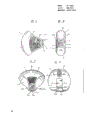
Fig. 1 is a kind of embodiment's of a plastic bending tube cover of the present invention side view, and wherein two tongues are engaged on together;
Fig. 2 is the end elevation of plastic bending tube cover shown in Figure 1;
Fig. 3 is the perspective view of plastic bending tube cover shown in Figure 2;
Fig. 4 is another perspective view of plastic bending tube cover shown in Figure 2, but two tongues are thrown off among the figure;
Fig. 5 is that plastic bending tube cover shown in Figure 2 is installed in the partial cross section side view on the logical bend sections of pipe;
Fig. 6 is the part enlarged view along X-X line intercepting among Fig. 5;
Fig. 7 is the another kind of embodiment's of the expression plastic bending tube cover of the present invention view that is similar to Fig. 5;
Fig. 8 is the perspective view of conventional curved pipe casing;
Fig. 9 is that conventional curved pipe casing shown in Figure 8 is installed in the partial cross section side view on the tube bends section.
The present invention can put into practice in a different manner, below with reference to Fig. 1 to Fig. 7 of accompanying drawing some embodiment is described.
Fig. 1 to Fig. 6 illustrates a kind of embodiment of plastic bending tube cover of the present invention.Curved pipe casing A comprises one substantially as the curved pipe casing portion 8 of 1/4th spherical shapes.Curved pipe casing A also comprises sector part 9 and 10, and they extend internally from the both sides of curved pipe casing portion 8.The end of sector part 9 is provided with tongue 9a, forms a meshing zone 9b on it.The end of sector part 10 also is provided with tongue 10a, forms an engaging hole 10c who comprises meshing zone 10b on it.
When tongue 9a inserted among the engaging hole 10c of tongue 10a, meshing zone 9b and 10b intermeshed, thereby stoped tongue 9a to throw off from engaging hole 10c or mobile.
In illustrational embodiment, the meshing zone 9b of tongue 9a comprises on the upper surface that is arranged on tongue 9a and forms the engagement projections or the spine of tooth bar and so on suitable shape.
As Fig. 3 and shown in Figure 6, the meshing zone 10b of tongue 10a is included in engagement projections or the spine that forms on the bridge plate internal surface of bridge 10d.Bridge 10d is arranged on the upper surface of tongue 10a, to form the engaging hole 10c that cooperates with tongue 10a, because can mesh the meshing zone 9b of tongue 9a.
Fig. 7 represents the another kind of embodiment of plastic bending tube cover of the present invention, it is to construct like this, make the meshing zone 10b of tongue 10a on the bridge plate internal surface of bridge 10d, comprise an Elastic Meshing part, bridge 10d is arranged on the tongue 10a, 10a cooperates with tongue, forms engaging hole 10c.The Elastic Meshing part has engagement projections on its lower surface, it meshes the meshing zone 9b of tongue 9a.The Elastic Meshing part is fixed on the end of internal surface of engaging hole 10c or bridge plate, and its other end is movable, makes it play spring sheet.
But the engagement of 9b and 10b is not limited to above-mentioned structure, and can take any form, and just they can stop tongue 9a to throw off from the engaging hole 10c of tongue 10a.
Plastic bending tube cover of the present invention is suitable for utilizing mold for plastics to make moulding.The plastic bending tube cover of moulding can have little of 0.5 to 1.0mm thickness like this.
Structure of the present invention plastic bending tube cover as above, use in such a way, make curved pipe casing portion 8 be installed on the bend sections of pipeline, then sector part 9 and 10 is centered around on the bend sections, so that tongue 9a is inserted among the engaging hole 10c of tongue 10a, thereby firmly fixes two tongue 9a and 10a.This causes meshing zone 9b and 10b to intermesh securely, thereby prevents that meshing zone 9b from throwing off from engaging hole 10c.
Therefore, plastic bending tube cover of the present invention is reliably, and they are fixedly mounted on the bent portion of pipeline in very simple mode.
As above finding is because only need an engagement operations basically, so plastic bending tube cover of the present invention is easy to and can be installed to effectively on the bend sections of pipeline between the meshing zone of two tongues.Simultaneously, the invention provides a kind of attractive polished appearance.Secondly, the present invention has avoided the tape wrap operation of needed trouble in prior art, causes the improvement of operating efficiency.
In addition, curved pipe casing of the present invention is made of plastics, so it can come to make fast accurately by one-step shaping, and is suitable for producing in batches, causes manufacture cost to reduce.
Obviously, can obtain a lot of kind remodeling of the present invention and modification according to top explanation.Therefore be appreciated that in claims scope, except top special narration, the also available embodied in other of the present invention.
Claims (9)
1, the curved pipe casing that a kind of bend pipe of pipeline or curved section are used, it comprises: a cover part that is 1/4th sphere shapes substantially, this cover part forms two openings crooked by one or angled hole is interconnected when operation or closed state, cover part is correspondingly crooked, thereby form the radially outskirt of a shaping and the radially inner region of a shaping, when cover part is in not operation or open mode, the radially inner region of this shaping is the breach from an opening to another opening, this cover part has the pair of joint sheet, each tab is positioned at each limit of breach, two tabs comprise intermeshing mechanism, thereby two tabs can be meshing with each other, therefore when cover part is in closed state, two tabs are meshing with each other and make the breach closure, it is characterized in that two tabs have first and second sector part, first sector part comprises first tongue that forms one first meshing zone on its free end, second sector part comprises second tongue that forms one second meshing zone on its free end, and look from the outside, first and second sector part have first and second ends of complete substantially spill respectively, and first and second sector part all have a series of arc reinforcement strengthening rib that form at its outer surface and have the radius of curvature that strengthens gradually.
2, curved pipe casing as claimed in claim 1 is characterized in that being made of plastics.
3, curved pipe casing as claimed in claim 1 is characterized in that described two tabs and cover part are extension parts one and that form cover part.
4, curved pipe casing as claimed in claim 1 is characterized in that described second meshing zone comprises the hole of first tongue that is used for packing into.
5, curved pipe casing as claimed in claim 4 is characterized in that described first meshing zone has the protuberance that forms on first upper tongue surface.
6, curved pipe casing as claimed in claim 5 is characterized in that described engaging hole is to be formed by the bridge on second tongue.
7, curved pipe casing as claimed in claim 6 is characterized in that described second meshing zone has the protuberance that forms on the internal surface of described bridge, to mesh the protuberance on first tongue.
8, curved pipe casing as claimed in claim 6 is characterized in that described second meshing zone has an Elastic Meshing part that is arranged on the described bridge internal surface, to mesh first tongue.
9, curved pipe casing as claimed in claim 8 is characterized in that described Elastic Meshing part forms engagement projections on its lower surface, and an end of Elastic Meshing part is fixed on the internal surface of described bridge, and its other end is freely.
Applications Claiming Priority (2)
| Application Number | Priority Date | Filing Date | Title |
|---|---|---|---|
| JP6612/87 | 1987-01-20 | ||
| JP1987006612U JPS63115990U (en) | 1987-01-20 | 1987-01-20 |
Publications (2)
| Publication Number | Publication Date |
|---|---|
| CN88100321A CN88100321A (en) | 1988-08-03 |
| CN1011332B true CN1011332B (en) | 1991-01-23 |
Family
ID=11643183
Family Applications (1)
| Application Number | Title | Priority Date | Filing Date |
|---|---|---|---|
| CN88100321A Expired CN1011332B (en) | 1987-01-20 | 1988-01-20 | Hood for pipe bending |
Country Status (10)
| Country | Link |
|---|---|
| US (1) | US4838318A (en) |
| JP (1) | JPS63115990U (en) |
| KR (1) | KR920006813B1 (en) |
| CN (1) | CN1011332B (en) |
| AU (1) | AU606373B2 (en) |
| DE (1) | DE3801377C2 (en) |
| ES (1) | ES2006271A6 (en) |
| FR (1) | FR2609775B1 (en) |
| GB (1) | GB2200181B (en) |
| HU (1) | HU199962B (en) |
Families Citing this family (22)
| Publication number | Priority date | Publication date | Assignee | Title |
|---|---|---|---|---|
| US5024249A (en) * | 1989-05-17 | 1991-06-18 | Carol Botsolas | Specialized one-piece pipefitting cover for insulated strainer and lateral 45 degree -Y |
| JPH05280686A (en) * | 1991-03-01 | 1993-10-26 | Fuji Heavy Ind Ltd | Method for repairing piping by shape memory alloy and member for repairing piping |
| US5318076A (en) * | 1992-11-13 | 1994-06-07 | Bloom Engineering Company, Inc. | Protective refractory locking mechanism |
| BR9207176A (en) * | 1992-11-17 | 1995-12-19 | Proprietary Technology Inc | Self-locking slotted corrugated tubing |
| JPH08505456A (en) * | 1992-11-17 | 1996-06-11 | プロプライアタリー・テクノロジー・インコーポレーテッド | Corrugated tubing with self-locking slit |
| US5901739A (en) * | 1993-10-29 | 1999-05-11 | Helmsderfer; John A. | Cover assembly with integral securing apparatus for covering undersink piping |
| US5685328A (en) * | 1993-10-29 | 1997-11-11 | Helmsderfer; John A. | Cover assembly and method for covering undersink piping |
| US5586568A (en) * | 1993-10-29 | 1996-12-24 | Helmsderfer; John A. | Cover assembly and method for covering undersink piping |
| US5915413A (en) * | 1993-10-29 | 1999-06-29 | Helmsderfer; John A. | Cover assembly with integral measurement indicia for covering undersink piping |
| US5795623A (en) * | 1993-10-29 | 1998-08-18 | Mcguire Manufacturing Co., Inc. | Cover assembly and method for covering undersink piping |
| US5701929A (en) * | 1993-10-29 | 1997-12-30 | Helmsderfer; John A. | Cover assembly having rapid installation features for covering undersink piping |
| DE9316978U1 (en) * | 1993-11-06 | 1995-03-02 | Leifeld Heinrich | Insulating jacket for pipe bends in water pipes |
| US5921283A (en) * | 1996-06-24 | 1999-07-13 | Alvern-Norway A/S | Protective cover for a fuel pump filler gun and method for protecting same |
| US6012480A (en) * | 1997-11-03 | 2000-01-11 | Helmsderfer; John A. | Cover assembly for covering undersink piping utilizing sliding cover pieces |
| US6182706B1 (en) | 1999-10-06 | 2001-02-06 | A. J. Gerrard & Company | Piping jacket |
| JP2002181282A (en) * | 2000-12-13 | 2002-06-26 | Takayuki Sawada | Elbow protective cover and its manufacturing method |
| JP2011247402A (en) * | 2010-05-26 | 2011-12-08 | Yamato Kogyo Kk | Elbow cover for piping |
| CN102494213A (en) * | 2011-12-08 | 2012-06-13 | 芜湖泰和管业有限公司 | Out-wall joint and assembly method thereof for embedded metal hose |
| CN102563215B (en) * | 2011-12-26 | 2015-07-29 | 汪仕斌 | Combustion gas is with going out silk crossover sub within the walls by buried corrugated stainless steel tubing |
| CN102644827A (en) * | 2012-04-28 | 2012-08-22 | 南京威尔化工有限公司 | Safe protective cover for chemical pipeline elbow |
| JP6989961B2 (en) * | 2019-02-15 | 2022-01-12 | 有限会社宮尻製作所 | Plumbing cover |
| US20210396345A1 (en) * | 2020-06-23 | 2021-12-23 | Distribution International, Inc. | Preformed insualtion fitting |
Family Cites Families (6)
| Publication number | Priority date | Publication date | Assignee | Title |
|---|---|---|---|---|
| US1261221A (en) * | 1917-03-20 | 1918-04-02 | Lewis B Dutcher | Hose-patch. |
| US3495629A (en) * | 1966-01-27 | 1970-02-17 | Chris J Botsolas | Method and device for covering pipefittings |
| US3578026A (en) * | 1969-02-24 | 1971-05-11 | Ford Motor Co | Jacket for flexible hose |
| US3960181A (en) * | 1971-05-14 | 1976-06-01 | Baur Charles B | Article for covering various pipefittings |
| US4426108A (en) * | 1981-06-17 | 1984-01-17 | Kesselman David A | Tamper indicator |
| US4669509A (en) * | 1986-05-30 | 1987-06-02 | Carol Botsolas | Pipe insulation fitting cover and fastening means and methods of using the same |
-
1987
- 1987-01-20 JP JP1987006612U patent/JPS63115990U/ja active Pending
-
1988
- 1988-01-12 US US07/142,952 patent/US4838318A/en not_active Expired - Fee Related
- 1988-01-19 AU AU10386/88A patent/AU606373B2/en not_active Ceased
- 1988-01-19 GB GB8801121A patent/GB2200181B/en not_active Expired - Fee Related
- 1988-01-19 DE DE3801377A patent/DE3801377C2/en not_active Expired - Fee Related
- 1988-01-19 KR KR1019880000423A patent/KR920006813B1/en not_active IP Right Cessation
- 1988-01-20 CN CN88100321A patent/CN1011332B/en not_active Expired
- 1988-01-20 FR FR888800601A patent/FR2609775B1/en not_active Expired
- 1988-01-20 ES ES888800128A patent/ES2006271A6/en not_active Expired
- 1988-01-20 HU HU88219A patent/HU199962B/en not_active IP Right Cessation
Also Published As
| Publication number | Publication date |
|---|---|
| AU606373B2 (en) | 1991-02-07 |
| DE3801377A1 (en) | 1988-07-28 |
| ES2006271A6 (en) | 1989-04-16 |
| JPS63115990U (en) | 1988-07-26 |
| DE3801377C2 (en) | 1996-04-04 |
| AU1038688A (en) | 1988-07-21 |
| KR920006813B1 (en) | 1992-08-20 |
| FR2609775B1 (en) | 1989-11-03 |
| HUT45761A (en) | 1988-08-29 |
| GB8801121D0 (en) | 1988-02-17 |
| HU199962B (en) | 1990-03-28 |
| GB2200181B (en) | 1991-01-23 |
| CN88100321A (en) | 1988-08-03 |
| FR2609775A1 (en) | 1988-07-22 |
| KR890012116A (en) | 1989-08-24 |
| US4838318A (en) | 1989-06-13 |
| GB2200181A (en) | 1988-07-27 |
Similar Documents
| Publication | Publication Date | Title |
|---|---|---|
| CN1011332B (en) | Hood for pipe bending | |
| CA1116658A (en) | Corner for decorative and protective molding strip | |
| US4310164A (en) | Composite reinforced sealing strip | |
| US4260655A (en) | Protective and decorative molding construction | |
| US6278060B1 (en) | Multi-part grommet | |
| CN1124695A (en) | Mechanism for ring bookbinding machine | |
| CN1135124A (en) | Housing latch system utilizing elastomeric interlocking band | |
| JPH07504757A (en) | fiber optic sheath | |
| EP0326938A3 (en) | Impact-modified polycarbonate | |
| US6659567B2 (en) | Wheel balance weight and process for manufacturing the same | |
| DE69515246D1 (en) | Process for the production of a polymer material with improved mechanical properties | |
| WO1990014543A3 (en) | Flexible pipe containing a composite material with an aluminium alloy matrix, and process for the manufacture of said material | |
| CA2183756A1 (en) | Hinge | |
| US4114240A (en) | Round back spring binder | |
| CN1106889A (en) | Vehicle door latch | |
| CN1203800C (en) | Vacuum cleaner hose | |
| DE69527572D1 (en) | Actuator in a vehicle with two continuously variable transmissions | |
| EP0411376A1 (en) | Panel, in particular for vehicle doors and relative method of manufacture | |
| DE19950447B4 (en) | Lighting unit and process for its manufacture | |
| GB2247487A (en) | Sealing strip carrier | |
| DE20306130U1 (en) | Ring binder file, has retainer for pivoting bracket formed by plastic component mounted on end of actuator lever | |
| ATE319956T1 (en) | CORRUGATED HOSE WITH AT LEAST ONE METAL REINFORCEMENT RING AND METHOD FOR PRODUCING SAME. | |
| GB1594911A (en) | Protective and decorative moulding construction | |
| EP0302258B1 (en) | Signalling horn | |
| KR820001807B1 (en) | Method of forming a corner for decorative and protective molding strip |
Legal Events
| Date | Code | Title | Description |
|---|---|---|---|
| C06 | Publication | ||
| PB01 | Publication | ||
| C10 | Entry into substantive examination | ||
| SE01 | Entry into force of request for substantive examination | ||
| C13 | Decision | ||
| GR02 | Examined patent application | ||
| C14 | Grant of patent or utility model | ||
| GR01 | Patent grant | ||
| C19 | Lapse of patent right due to non-payment of the annual fee | ||
| CF01 | Termination of patent right due to non-payment of annual fee |