CN101032807A - Omnipotent potent clamp tool and spanner - Google Patents
Omnipotent potent clamp tool and spanner Download PDFInfo
- Publication number
- CN101032807A CN101032807A CN 200610054124 CN200610054124A CN101032807A CN 101032807 A CN101032807 A CN 101032807A CN 200610054124 CN200610054124 CN 200610054124 CN 200610054124 A CN200610054124 A CN 200610054124A CN 101032807 A CN101032807 A CN 101032807A
- Authority
- CN
- China
- Prior art keywords
- caliper
- main
- adjustable
- jaw
- moving caliper
- Prior art date
- Legal status (The legal status is an assumption and is not a legal conclusion. Google has not performed a legal analysis and makes no representation as to the accuracy of the status listed.)
- Pending
Links
Images


Abstract
The present invention relates to clamping tool, and is especially universal powerful pliers and spanner. The universal powerful pliers feature that the fixed plier body has no screw pair and small body while the movable pliers body has several screw pairs and small plier bodies, including a left outer movable plier body, a left movable plier body, a main movable plier body, a right movable plier body and a right outer movable plier body, in the total length equal the length of the fixed plier body. The present invention has the advantages of universal clamping, powerful clamping force, high use efficiency, fast locating, simple structure and low cost.
Description
Technical background
The invention belongs to clamping class field of tool, be specifically related to flat mouthful cutting pliers, flat mouthful electricians' plier, locking pliers, water pump pliers, slip-joint pliers, fork spanner, double offset ring spanner, combination wrenches, multifunctional wrench, box spanner, inner hexagon spanner, monkey wrench, ratchet spanner, F shape tap wrench, speeder wrench.Bench vice, bench vice, machine vise, hand vice, pipe vice, G word folder, C word folder, F word folder, monkey wrench, telescopic tyre wrench, the quick binding clasp of plastics garden steel, the quick carpenters' clamp of plastics band steel, bench vise for wood working, gantry vice and the clamping utensil that hand is used or machine is used that utilizes the screw pair principle
Technical background
The clamping appliances of prior art has the three major types type: first type is according to the screw pair principle: screw mandrel promotes a moving caliper (the moving palm) with the relative rotary motion of nut and does to move relative to straight line to a fixed caliper (the fixed palm), thereby the jaw that constitutes pair of parallel carries out clamping work, as milling machine, drilling machine, planer, the various machine vises that use on grinding machine or other lathe, the bench vice that hand is used, bench vice, hand vice, pipe vice, gantry vice, G word folder, C word folder, F word folder, monkey wrench, telescopic tyre wrench, the quick binding clasp of plastics garden steel, the quick carpenters' clamp of plastics band steel, tongers such as bench vise for wood working; Second type is to constitute parallel jaw according to lever principle, as flat mouthful cutting pliers, flat mouthful electricians' plier, locking pliers, water pump pliers, slip-joint pliers, F shape tap wrench; Also having one type is the parallel jaw fixed, as fork spanner, double offset ring spanner, combination wrenches, multifunctional wrench, box spanner, inner hexagon spanner, ratchet spanner, speeder wrench etc.This clamping work of three types has a common ground: be exactly to have only the parallel jaw can only the clamping equilateral or the workpiece or the nut of corner angle comparison rule, screw rod, if clamping abnormity as non-positive equilateral, bool, other edges or the irregular workpiece of corner angle heavy wear, nut and screw rod or tubing string, its chucking power weakens relatively even is entirely ineffective, if a parallel jaw is wanted clamping abnormity object such as non-positive equilateral in practical operation, bool or other edges are irregular or the object of corner angle heavy wear must rely on special frock of making or anchor clamps just can carry out clamping with auxiliary jaw; Besides in processing practice for the workpiece of the batch machining of same kind, same specification, because of well-known tolerance reason, its each workpiece certainly leads to difference in size, so each parallel jaw can only workpiece of clamping, want with jaw directly side by side two or more workpiece of clamping be impossible to improve tonger efficient.For a long time, for efficient and its chucking power of enhancing that improves tonger, just must produce the frock or the auxiliary clamp that can mate jaw and workpiece fully earlier, this certainly will cause time-consuming, bothersome, the effort of making frock or auxiliary clamp again, take material or the like weak point.
Summary of the invention
The present invention is directed to above-mentioned deficiency, provide the jaw direct convenience fast, do not rely on frock or anchor clamps just can be simultaneously two or more workpiece of clamping side by side, or the directly tonger and the spanner of the various special-shaped workpieces of clamping.
Technical scheme of the present invention is:
A. on vice base (28) or on main fixed caliper (3) axis at rotatable pincers seat (4), be embedded in the mother nut (5) on the main moving caliper (24) with driving screw (2), main screw pair, and promoting main moving caliper (24) along moving to main fixed caliper (3) on the main guide rail plane, main fixed caliper (3) then constitutes main jaw with main moving caliper (26); On the left lateral sides of main fixed caliper (3), establish protruding rail (35), protruding rail (35) then is embedded in the groove (37) on the side, right side of left adjustable fixed caliper (34), left solid nut (33) edge is enclosed within on the solid screw rod (36) in a left side and becomes the left-hand screw pair, does the opposing parallel slip to promote left adjustable fixed caliper (34) along the guide pass on main fixed caliper (3) right side; On the side, right side of main fixed caliper (3), establish protruding rail (30), protruding rail (30) then is embedded in the groove (38) on the side, right side of right adjustable fixed caliper (32), right solid nut (31) edge is enclosed within and becomes right solid screw pair on the solid screw rod (29) in the right side, does the opposing parallel slip to promote right adjustable fixed caliper (32) along the guide pass in main fixed caliper (3) left side; On the left lateral sides of main moving caliper (24), establish protruding rail (14), protruding rail (14) then is embedded in the groove (39) on the side, right side of left adjustable moving caliper (17), left side nut alive (19) is inlayed and is enclosed within to become on the left side screw rod alive (13) left side screw pair alive, does the opposing parallel slip to promote left adjustable moving caliper (17) along the guide pass on main moving caliper (24) right side; On the side, right side of main moving caliper (24), establish protruding rail (11), protruding rail (11) then is embedded in the groove (40) on the left lateral sides of right adjustable moving caliper (26), right nut (6) edge of living is enclosed within and becomes the right screw pair of living on the right side screw rod alive (12), does the opposing parallel slip to promote right adjustable moving caliper (26) along the guide pass in main moving caliper (24) left side; The adjustable fixed caliper in a left side (34) constitutes left jaw with left adjustable moving caliper (17), right adjustable fixed caliper (32) constitutes right jaw with right adjustable moving caliper (26), when rotation driving screw (2), main moving caliper (24) then drives left adjustable moving caliper (17) and right adjustable moving caliper (26) simultaneously to main fixed caliper (3), a left side adjustable fixed caliper (34), right adjustable fixed caliper (32) direction is made same moved further, so the present invention possesses the not only interdependence of being made up of five screw pairs but also can transpose mutually and relatively independent main jaw, left side jaw, right jaw is totally three jaws, just three workpieces with different sizes of energy clamping, or clamping shaped piece, irregular workpiece in edge or even spherical parts.
B. establish the mechanism that a plurality of screw pairs are formed a plurality of minutes jaws according to the described jaw of A part both sides, with tongers such as the hand vice of first kind of screw pair principle type, pipe vice, gantry vice, G word folder, C word folder, F word folder, monkey wrench, telescopic tyre wrench, the quick binding clasp of plastics garden steel, the quick carpenters' clamp of plastics band steel, benchs vise for wood working; Flat mouthful of cutting pliers of second kind of lever principle type, flat mouthful electricians' plier, locking pliers, water pump pliers, slip-joint pliers, F shape tap wrench; The jaw both sides of the fork spanner of the third type parallel jaw fixed type, double offset ring spanner, combination wrenches, multifunctional wrench, box spanner, inner hexagon spanner, ratchet spanner, speeder wrench are provided with screw pair and divide jaw.
C. establish the mechanism that a plurality of screw pairs are formed a plurality of minutes jaws according to the described jaw of A part both sides, the screw pair branch is listed in flat mouthful cutting pliers, flat mouthful electricians' plier, locking pliers, water pump pliers, slip-joint pliers, fork spanner, double offset ring spanner, combination wrenches, multifunctional wrench, box spanner, inner hexagon spanner, monkey wrench, ratchet spanner, F shape tap wrench, speeder wrench, hand vice, pipe vice, G word folder, C word folder, F word folder, monkey wrench, telescopic tyre wrench, the quick binding clasp of plastics garden steel, the quick carpenters' clamp of plastics band steel, radial bore or drill through the hole and tapping on each limit of the jaw of gantry vice or the polygon wall body, the screw rod that is mated promptly is that a plurality of adjustabilitys are divided jaw.
The present invention has following advantage:
1, powerful clamping reinforcement several times: the present invention can constitute main jaw by a plurality of screw pairs, left side jaw, a plurality of jaws and a plurality of pincers palms such as right jaw, with traditional vice and hand with a screw pair of clamping constitute a jaw totally two pincers palms compare, the backward technology that actual stressed bite when thoroughly having changed the rectangular or bar in clamping of prior art vice is three to four, increase to nine to 12 of the stressed bites of actual face, its clamping force advantage is conspicuous, has especially strengthened balanced application of force clamping or the segmentation clamping of whole jaws of tonger and spanner to workpiece.
2, clamping apparatus is eliminated in omnipotent clamping: the opening width of left jaw of the present invention and right jaw is not subjected to the restriction of main jaw, also can do to regulate arbitrarily on the contrary according to the opening width of main jaw, this has just satisfied the clamping special-shaped workpiece must the clamping condition of mating special-shaped impetus, so, no matter be trapezoidal workpiece, garden shape workpiece, ellipse garden shape and spherical work-piece, or the various special-shaped workpieces such as workpiece of edge irregular or corner angle heavy wear, the present invention all can not need frock or auxiliary clamp, just directly clamping, compare with spanner with clamping with traditional vice and hand, omitted the program of making frock or auxiliary clamp, had when saving in pincers worker or the machined practice, save trouble, laborsaving, material-saving or the like significant advantage.
3, efficient clamping one pincers are when counting pincers: the present invention has parallel three jaws arranged side by side at least, three workpiece of the parallel clamping arranged side by side of energy, if again the left lateral sides of the adjustable fixed caliper in a left side (34) establish the outer fixedly screw pair in a left side and connection left outside adjustable fixed caliper, adjustable moving caliper outside an activity screw pair and the connection left side outside the left lateral sides of the adjustable moving caliper in a left side (17) is established a left side, thus constitute the outer jaw in a left side; Adjustable fixed caliper outside the right outer fixedly screw pair and the connection right side are established in the side, right side of the adjustable fixed caliper in the right side (32) again, adjustable moving caliper outside the activity screw pair and the connection right side outside the right side is established in the side, right side of the adjustable moving caliper in the right side (26), thus constitute the outer jaw in the right side.The present invention just can have five jaws arranged side by side that nine screw pairs are formed, and reaches the purpose of five workpiece of parallel clamping arranged side by side.Put off by this mechanism, the present invention still can constitute more jaw in the intensity allowed band of main screw pair.
4, self-align efficient and convenient by force: left and right jaw of the present invention is to be driven in moving of main jaw and to move, therefore in case regulate the suitable location of definite good left and right jaw to required holding workpiece, only need to rotate driving screw, its left and right jaw or in addition will be with main jaw with the automatic clamping of moved further and locate it and answer processing work, this is to have improved efficiency greatly for batch machining.
5. simple in structure, the present invention with low cost compares with traditional tonger and spanner, and more more several screw rods, nut and change manufacture craft are so production cost is very low.
Description of drawings
Fig. 1 is the schematic side view of the invention process at bench vice.
Fig. 2 is that Fig. 1 is the schematic top plan view of the invention process at bench vice;
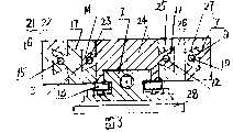
Fig. 3 is the positive cross-sectional schematic of reduced form five jaw vices of the embodiment of the invention;
Fig. 4 is that Fig. 3 is the reduced form five jaw vice schematic top plan view of present embodiment;
Specific embodiments
Be described further below in conjunction with drawings and Examples:
Embodiment 2: certainly the present invention can simplify, and Fig. 3 and Fig. 4 promptly are reduced form machines with five jaw vices.Parallel many jaws arranged side by side of the present invention not only are confined to three jaws or below three jaws, but should obtain bigger application on this theory of mechanics basis, are made into the many jaws vice greater than three jaws.The left fixed caliper (34) that the side, both sides is gone up main fixed caliper (3) in concrete making exactly all omits with right fixed caliper (32) and corresponding screw pair, still keep the left moving caliper (17) on main moving caliper (24) side, both sides, right moving caliper (26) and corresponding screw pair, on the left lateral sides of the adjustable moving caliper in a left side (17), establish dove-tail form protruding rail (21) again, left side outer nut (20) is embedded in the dove-tail form groove (22) on the side, right side of the outer adjustable moving caliper (16) in a left side, and and left external screw rod (15) constitute left external spiral pair, move as the plane to promote the outer dove-tail form guide pass of adjustable moving caliper (16) on the adjustable moving caliper in a left side (17) in a left side, thereby constitute the outer jaw in a left side; On the side, right side of the adjustable moving caliper in the right side (26), establish dove-tail form protruding rail (9), right outer nut (8) is embedded in the dove-tail form groove (27) on right outer adjustable moving caliper (7) left lateral sides, and and right external screw rod (10) constitute right external spiral pair, move as the plane along right adjustable moving caliper (26) dove-tail form guide pass to promote right outer adjustable moving caliper (7), thereby constitute right outer jaw.Vice is just formed parallel five jaws arranged side by side with five screw pairs, reaches the special-shaped workpiece that five workpiece of parallel clamping arranged side by side or clamping resemble crank, bent axle and so on.Certainly, this just requires the driving screw holding capacity bigger, can support the chucking power sum of a plurality of minutes jaws of the present invention fully.
In brief, first feature of the omnipotent powerful vice of reduced form of the present invention is: the side, both sides of (3) does not have any screw pair and divides caliper on the fixed caliper, and there are one or more screw pairs the side, both sides on the main moving caliper (24) and divide caliper, second feature is: a left side outer moving caliper (16), left moving caliper (17), main moving caliper (24), the right outer moving caliper (7) of right moving caliper (26), the length sum arranged side by side of a plurality of moving calipers should equal the length of fixed caliper (3) in other words.Reduced form will be poorer slightly than the adjustability characteristic of reduced form not.
Embodiment 3: the advantage of the omnipotent powerful vice of reduced form shows in (3) on the fixed caliper and is arranged on centre position on main guide rail (1) plane, and the two ends on main guide rail (1) plane all are provided with the main moving calipers of being made of a plurality of adjustable movable branch calipers a plurality of screw pairs, draw close when driving screw (2) two main moving calipers of promotion (3) on the fixed caliper in centre position just to have constituted the omnipotent powerful vice of double row.The Lower Half level of rotatable pincers seat is dissectd, its cutting plane all is made into the sliding contact surface of the garden arc that can mate mutually again and engraves radian, the present invention constitutes the omnipotent powerful vice of universal type again; The bottom that should be noted that main moving caliper of the present invention (24) is fastening with lower platen (18) and screw, makes its main moving caliper (24) can be along sliding on main guide rail (1) plane; Described protruding rail and groove are to mate mutually, and can make is T type or dove-tail form, garden shape or other shape, but are the best with the dove-tail form, and the residing position of protruding rail and groove is to exchange.
Embodiment 4: form a plurality of minutes jaw principles according to a plurality of screw pairs of the present invention, with tongers such as the hand vice of first kind of screw pair principle type, pipe vice, gantry vice, G word folder, C word folder, F word folder, monkey wrench, telescopic tyre wrench, the quick binding clasp of plastics garden steel, the quick carpenters' clamp of plastics band steel, benchs vise for wood working; Flat mouthful of cutting pliers of second kind of lever principle type, flat mouthful electricians' plier, locking pliers, water pump pliers, slip-joint pliers, F shape tap wrench; The fork spanner of the third type parallel jaw fixed type, double offset ring spanner, combination wrenches, multifunctional wrench, box spanner, inner hexagon spanner, ratchet spanner, the parallel jaw both sides of speeder wrench are provided with screw pair and divide jaw, thereby constitute omnipotent powerful hand vice respectively, omnipotent powerful pipe vice, omnipotent powerful C word folder, omnipotent powerful G word pincers, omnipotent powerful F word folder, omnipotent powerful monkey wrench, the telescopic tyre wrench of omnipotent brute force, the quick binding clasp of omnipotent strong plastic garden steel, the quick carpenters' clamp of omnipotent strong plastic band steel, omnipotent powerful bench vise for wood working, omnipotent powerful gantry vice, the flat mouthful cutting pliers of omnipotent brute force, flat mouthful of electrician's cutting pliers of omnipotent brute force, omnipotent powerful locking pliers, omnipotent powerful water pump pliers, omnipotent powerful slip-joint pliers, omnipotent powerful F shape tap wrench, omnipotent powerful fork spanner, omnipotent powerful double offset ring spanner, omnipotent powerful combination wrenches, omnipotent powerful multifunctional wrench, omnipotent powerful box spanner, omnipotent powerful inner hexagon spanner, omnipotent powerful ratchet spanner, omnipotent powerful speeder wrench.
Embodiment 5: the mechanism of forming a plurality of minutes jaws according to a plurality of screw pairs of the present invention, another kind of distortion of the present invention is that the screw pair branch is listed in flat mouthful cutting pliers, flat mouthful electricians' plier, locking pliers, water pump pliers, slip-joint pliers, fork spanner, double offset ring spanner, combination wrenches, multifunctional wrench, box spanner, inner hexagon spanner, monkey wrench, ratchet spanner, F shape tap wrench, speeder wrench, hand vice, pipe vice, G word folder, C word folder, F word folder, monkey wrench, telescopic tyre wrench, the quick binding clasp of plastics garden steel, the quick carpenters' clamp of plastics band steel, radial bore or drill through the hole and tapping on each limit of the jaw of gantry vice or the polygon wall body, the screw rod that is mated promptly is that a plurality of adjustabilitys are divided jaw, reaches the effect of omnipotent powerful clamping.The screw pair of this distortion and the design of branch jaw, especially very important to the small sized product in above-mentioned tonger and the spanner, then be omnipotent powerful clamping design necessary condition to special shape products such as double offset ring spanner, box spanner, inner hexagon spanner, ratchet spanneres.
Claims (4)
1. omnipotent potent clamp tool and spanner is characterized in that:
A. on vice base (28) or on main fixed caliper (3) axis at rotatable pincers seat (4), be embedded in the mother nut (5) on the main moving caliper (24) with driving screw (2), main screw pair, and promoting main moving caliper (24) along moving to main fixed caliper (3) on the main guide rail plane, main fixed caliper (3) then constitutes main jaw with main moving caliper (26); On the left lateral sides of main fixed caliper (3), establish protruding rail (35), protruding rail (35) then is embedded in the groove (37) on the side, right side of left adjustable fixed caliper (34), left solid nut (33) edge is enclosed within on the solid screw rod (36) in a left side and becomes the left-hand screw pair, does the opposing parallel slip to promote left adjustable fixed caliper (34) along the guide pass on main fixed caliper (3) right side; On the side, right side of main fixed caliper (3), establish protruding rail (30), protruding rail (30) then is embedded in the groove (38) on the side, right side of right adjustable fixed caliper (32), right solid nut (31) edge is enclosed within and becomes right solid screw pair on the solid screw rod (29) in the right side, does the opposing parallel slip to promote right adjustable fixed caliper (32) along the guide pass in main fixed caliper (3) left side; On the left lateral sides of main moving caliper (24), establish protruding rail (14), protruding rail (14) then is embedded in the groove (39) on the side, right side of left adjustable moving caliper (17), left side nut alive (19) is inlayed and is enclosed within to become on the left side screw rod alive (13) left side screw pair alive, does the opposing parallel slip to promote left adjustable moving caliper (17) along the guide pass on main moving caliper (24) right side; On the side, right side of main moving caliper (24), establish protruding rail (11), protruding rail (11) then is embedded in the groove (40) on the left lateral sides of right adjustable moving caliper (26), right nut (6) edge of living is enclosed within and becomes the right screw pair of living on the right side screw rod alive (12), does the opposing parallel slip to promote right adjustable moving caliper (26) along the guide pass in main moving caliper (24) left side; The adjustable fixed caliper in a left side (34) constitutes left jaw with left adjustable moving caliper (17), right adjustable fixed caliper (32) constitutes right jaw with right adjustable moving caliper (26), when rotation driving screw (2), main moving caliper (24) then drives left adjustable moving caliper (17) and right adjustable moving caliper (26) simultaneously to main fixed caliper (3), a left side adjustable fixed caliper (34), right adjustable fixed caliper (32) direction is made same moved further, so possess the not only interdependence of being made up of five screw pairs but also can transpose also relatively independent main jaw mutually, left side jaw, right jaw is totally three branch jaws.
B. establish the mechanism that a plurality of screw pairs are formed a plurality of minutes jaws according to the described jaw of A part both sides, the jaw both sides of hand vice, pipe vice, gantry vice, G word folder, C word folder, F word folder, monkey wrench, telescopic tyre wrench, the quick binding clasp of plastics garden steel, the quick carpenters' clamp of plastics band steel, bench vise for wood working, flat mouthful cutting pliers, a flat mouth electricians' plier, locking pliers, water pump pliers, slip-joint pliers, F shape tap wrench, double offset ring spanner, combination wrenches, multifunctional wrench, speeder wrench are provided with screw pair and branch jaw.
C. the mechanism of forming a plurality of minutes jaws according to the described a plurality of screw pairs of A part, the screw pair branch is listed in flat mouthful cutting pliers, flat mouthful electricians' plier, locking pliers, water pump pliers, slip-joint pliers, fork spanner, double offset ring spanner, combination wrenches, multifunctional wrench, box spanner, inner hexagon spanner, monkey wrench, ratchet spanner, F shape tap wrench, speeder wrench, hand vice, pipe vice, G word folder, C word folder, F word folder, monkey wrench, telescopic tyre wrench, the quick binding clasp of plastics garden steel, the quick carpenters' clamp of plastics band steel, radial bore or drill through the hole and tapping on each limit of the jaw of gantry vice or the polygon wall body, the coupling screw rod promptly is that adjustability is divided jaw.
2. according to described omnipotent potent clamp tool of the A of claim 1 and spanner, it is characterized in that: again the left lateral sides of the adjustable fixed caliper in a left side (34) establish the outer fixedly screw pair in a left side and connection left outside adjustable fixed caliper, adjustable moving caliper outside an activity screw pair and the connection left side outside the left lateral sides of the adjustable moving caliper in a left side (17) is established a left side, thus constitute the outer jaw in a left side; Adjustable fixed caliper outside the right outer fixedly screw pair and the connection right side are established in the side, right side of the adjustable fixed caliper in the right side (32) again, adjustable moving caliper outside the activity screw pair and the connection right side outside the right side is established in the side, right side of the adjustable moving caliper in the right side (26), thus constitute the outer jaw in the right side.This tonger just can divide jaw side by side by five that nine screw pairs are formed, reaches the purpose of five workpiece of parallel clamping arranged side by side.Put off by this mechanism, in the intensity allowed band of main screw pair, still can constitute more jaw.
3. according to the A and the right 2 described omnipotent potent clamp tool and the spanners of claim 1, it is characterized in that: be that the left fixed caliper (34) that main fixed caliper (3) is gone up the side, both sides is all omitted with right fixed caliper (32) and corresponding screw pair, still keep the left moving caliper (17) on main moving caliper (24) side, both sides, right moving caliper (26) and corresponding screw pair, on the left lateral sides of the adjustable moving caliper in a left side (17), establish protruding rail (21) and left outer nut (20) again and connects left outside groove (22) and left external screw rod (15) on the side, right side of adjustable moving caliper (16), then constitute left external spiral pair and move as the plane, thereby constitute the outer jaw in a left side with the guide pass that promotes on the outer adjustable left moving caliper of adjustable moving caliper (16) (17) in a left side; On the side, right side of the adjustable moving caliper in the right side (26), establish protruding rail (9) and right outer nut (8), and groove (27) and right external screw rod (10) on the left lateral sides of the right outer adjustable moving caliper (7) of connection, then constitute right external spiral pair, move as the plane along the guide pass of right adjustable moving caliper (26) to promote right outer adjustable moving caliper (7), thereby constitute right outer jaw.The side, both sides that is (3) on the fixed caliper does not have any screw pair and divides caliper, and there are one or more screw pairs the side, both sides on the main moving caliper (24) and divide caliper; A left side outer moving caliper (16), left moving caliper (17), main moving caliper (24), the right outer moving caliper (7) of right moving caliper (26), the length sum arranged side by side of a plurality of moving calipers should equal the length of fixed caliper (3) in other words conj.or perhaps.
4. according to the A of claim 1 part and described omnipotent potent clamp tool of claim 2 and spanner, it is characterized in that: the centre position on main guide rail (1) plane is provided with (3) on the fixed caliper, and the two ends on main guide rail (1) plane all are provided with by a plurality of screw pairs and form a plurality of adjustable movable main moving calipers that divide calipers, and (3) have then constituted the omnipotent powerful vice of double row on two main moving calipers and the fixed caliper.The Lower Half level of rotatable pincers seat is dissectd, again its cutting plane all is made into the sliding contact surface of the garden arc that can mate mutually and engraves radian, then constitute the omnipotent powerful vice of universal type; Main moving caliper (24) is through lower platen (18), makes its main moving caliper (24) can be along sliding on main guide rail (1) plane; Described protruding rail and groove are that T type, dove-tail form, garden type or other shape match each other, and its position is can exchange mutually.
Priority Applications (1)
| Application Number | Priority Date | Filing Date | Title |
|---|---|---|---|
| CN 200610054124 CN101032807A (en) | 2006-03-10 | 2006-03-10 | Omnipotent potent clamp tool and spanner |
Applications Claiming Priority (1)
| Application Number | Priority Date | Filing Date | Title |
|---|---|---|---|
| CN 200610054124 CN101032807A (en) | 2006-03-10 | 2006-03-10 | Omnipotent potent clamp tool and spanner |
Publications (1)
| Publication Number | Publication Date |
|---|---|
| CN101032807A true CN101032807A (en) | 2007-09-12 |
Family
ID=38729647
Family Applications (1)
| Application Number | Title | Priority Date | Filing Date |
|---|---|---|---|
| CN 200610054124 Pending CN101032807A (en) | 2006-03-10 | 2006-03-10 | Omnipotent potent clamp tool and spanner |
Country Status (1)
| Country | Link |
|---|---|
| CN (1) | CN101032807A (en) |
Cited By (5)
| Publication number | Priority date | Publication date | Assignee | Title |
|---|---|---|---|---|
| CN106335013A (en) * | 2016-10-19 | 2017-01-18 | 中航飞机股份有限公司西安飞机分公司 | Flexible vice clamp |
| CN107538364A (en) * | 2016-06-24 | 2018-01-05 | 万象设计江苏有限责任公司 | Self-priming jaw harden structure |
| CN108039519A (en) * | 2018-01-10 | 2018-05-15 | 香河昆仑化学制品有限公司 | A kind of simple soft-package battery hot pressing battery formation clamp |
| CN109128902A (en) * | 2018-09-05 | 2019-01-04 | 中国航发动力股份有限公司 | A kind of die forging rotor blade processing tool |
| CN109732498A (en) * | 2019-03-25 | 2019-05-10 | 无锡易通精密机械股份有限公司 | A kind of Bidirectional flat-nose pliers |
-
2006
- 2006-03-10 CN CN 200610054124 patent/CN101032807A/en active Pending
Cited By (6)
| Publication number | Priority date | Publication date | Assignee | Title |
|---|---|---|---|---|
| CN107538364A (en) * | 2016-06-24 | 2018-01-05 | 万象设计江苏有限责任公司 | Self-priming jaw harden structure |
| CN106335013A (en) * | 2016-10-19 | 2017-01-18 | 中航飞机股份有限公司西安飞机分公司 | Flexible vice clamp |
| CN108039519A (en) * | 2018-01-10 | 2018-05-15 | 香河昆仑化学制品有限公司 | A kind of simple soft-package battery hot pressing battery formation clamp |
| CN108039519B (en) * | 2018-01-10 | 2023-10-13 | 宜宾昆仑新能源有限公司 | Simple soft-package battery hot-pressing formation clamp |
| CN109128902A (en) * | 2018-09-05 | 2019-01-04 | 中国航发动力股份有限公司 | A kind of die forging rotor blade processing tool |
| CN109732498A (en) * | 2019-03-25 | 2019-05-10 | 无锡易通精密机械股份有限公司 | A kind of Bidirectional flat-nose pliers |
Similar Documents
| Publication | Publication Date | Title |
|---|---|---|
| CN102990433B (en) | The auxiliary locator of machine vice | |
| CN202106218U (en) | Replaceable flat tongs for clamping multiple barstocks | |
| CN203636663U (en) | Multifunctional precise flat-nose pliers | |
| CN108202242B (en) | Clamping tool | |
| CN203875648U (en) | Self-adaptive flat tongs | |
| CN101032807A (en) | Omnipotent potent clamp tool and spanner | |
| CN101121256A (en) | Multifunctional quick replaceable double-acting clamp paw bench vice | |
| CN202292184U (en) | Automatic centering flat tongs for machine | |
| CN105014421A (en) | Self-adaptive flat tongs | |
| CN200984712Y (en) | Universal strong clamp and spanner | |
| CN103056691A (en) | Multifunctional combination vise for machine | |
| CN112692611A (en) | Quick adjustment formula flat-nose pliers | |
| CN209774353U (en) | Angle-adjustable plane grinding clamping device | |
| CN202592059U (en) | Flat tongs for machines | |
| CN211332227U (en) | Quick clamping bench vice | |
| CN2657852Y (en) | Multifunction open pliers | |
| CN202278410U (en) | Multipurpose precision gad tongs without lead screw | |
| CN202239858U (en) | Adjustable combined clamp special for milling machine | |
| CN213730580U (en) | Detachable multifunctional bench vice | |
| CN207189485U (en) | Quick-clamping bench vice | |
| CN218461914U (en) | Quick-change multifunctional flat tongs | |
| CN211102882U (en) | Hydraulic machine tool vice with 4 jaws | |
| CN218017972U (en) | Vice capable of clamping parts with irregular shapes | |
| CN220218240U (en) | Positioning open spanner | |
| CN213439354U (en) | Multifunctional locking pliers |
Legal Events
| Date | Code | Title | Description |
|---|---|---|---|
| C06 | Publication | ||
| PB01 | Publication | ||
| C57 | Notification of unclear or unknown address | ||
| DD01 | Delivery of document by public notice |
Addressee: Zheng Hengchun Document name: Notice of publication of application for patent for invention |
|
| C57 | Notification of unclear or unknown address | ||
| DD01 | Delivery of document by public notice |
Addressee: Zheng Hengchun Document name: Notification before expiration of term |
|
| C10 | Entry into substantive examination | ||
| SE01 | Entry into force of request for substantive examination | ||
| DD01 | Delivery of document by public notice |
Addressee: Zheng Hengchun Document name: Notification that Application Deemed to be Withdrawn |
|
| C02 | Deemed withdrawal of patent application after publication (patent law 2001) | ||
| WD01 | Invention patent application deemed withdrawn after publication |
Open date: 20070912 |