CN1010150B - Lightning conductor - Google Patents
Lightning conductorInfo
- Publication number
- CN1010150B CN1010150B CN86108676.7A CN86108676A CN1010150B CN 1010150 B CN1010150 B CN 1010150B CN 86108676 A CN86108676 A CN 86108676A CN 1010150 B CN1010150 B CN 1010150B
- Authority
- CN
- China
- Prior art keywords
- surface element
- earth
- brace
- lightning
- air gap
- Prior art date
- Legal status (The legal status is an assumption and is not a legal conclusion. Google has not performed a legal analysis and makes no representation as to the accuracy of the status listed.)
- Expired
Links
- 239000004020 conductor Substances 0.000 title abstract description 5
- 238000010891 electric arc Methods 0.000 claims description 10
- 230000015572 biosynthetic process Effects 0.000 abstract description 7
- 230000003068 static effect Effects 0.000 abstract description 2
- 230000005684 electric field Effects 0.000 description 13
- 238000009413 insulation Methods 0.000 description 6
- 238000007599 discharging Methods 0.000 description 3
- 230000000694 effects Effects 0.000 description 3
- 239000000700 radioactive tracer Substances 0.000 description 3
- 238000013459 approach Methods 0.000 description 2
- 230000005686 electrostatic field Effects 0.000 description 2
- 230000006872 improvement Effects 0.000 description 2
- 230000004044 response Effects 0.000 description 2
- 241001122767 Theaceae Species 0.000 description 1
- 230000009471 action Effects 0.000 description 1
- 230000008901 benefit Effects 0.000 description 1
- 230000005540 biological transmission Effects 0.000 description 1
- 230000008859 change Effects 0.000 description 1
- 230000008094 contradictory effect Effects 0.000 description 1
- 238000010586 diagram Methods 0.000 description 1
- 230000005611 electricity Effects 0.000 description 1
- 230000005669 field effect Effects 0.000 description 1
- 230000000977 initiatory effect Effects 0.000 description 1
- 239000002184 metal Substances 0.000 description 1
- 238000000034 method Methods 0.000 description 1
- 235000012771 pancakes Nutrition 0.000 description 1
- 239000002245 particle Substances 0.000 description 1
- 230000002085 persistent effect Effects 0.000 description 1
- 230000005855 radiation Effects 0.000 description 1
- 230000000630 rising effect Effects 0.000 description 1
- 238000005728 strengthening Methods 0.000 description 1
Images


Classifications
-
- H—ELECTRICITY
- H02—GENERATION; CONVERSION OR DISTRIBUTION OF ELECTRIC POWER
- H02G—INSTALLATION OF ELECTRIC CABLES OR LINES, OR OF COMBINED OPTICAL AND ELECTRIC CABLES OR LINES
- H02G13/00—Installations of lightning conductors; Fastening thereof to supporting structure
-
- H—ELECTRICITY
- H02—GENERATION; CONVERSION OR DISTRIBUTION OF ELECTRIC POWER
- H02G—INSTALLATION OF ELECTRIC CABLES OR LINES, OR OF COMBINED OPTICAL AND ELECTRIC CABLES OR LINES
- H02G13/00—Installations of lightning conductors; Fastening thereof to supporting structure
- H02G13/80—Discharge by conduction or dissipation, e.g. rods, arresters, spark gaps
Abstract
A lightning conductor (10) having a surface element (14) insulated from an earth rod (12). The surface element (14) is substantially continuous, but has an aperture (17) defining an air gap (18). The tip (13) of the earth rod (12) is located in the vicinity of said aperture (17). In atmospheric conditions existing before lightning discharges, arcing occurs between the surface element (14) and the earth rod (12). This creates plasma about the tip (13) of the earth rod, leading to upward leader formation. A high impedance static drain (20) may be connected between the surface element (14) and the earth rod (12).
Description
The present invention relates to the improvement of lightning arrester.
The general general lightning arrester of all thinking the invention of Benjamin Franklin.As far back as 1752, Franklin and three friends just demonstrated by experiment, can attract with sharp-pointed metalwork.Just write out a detailed description about lightning rod Franklin in 1753, since at that time rising, the lightning arrester of similar pointed bar is installed in the top of building, so just can absorb thunder discharge, has been known as franklin rod.
First proposes the notion of his lightning protection from the Franklin, the improvement of existing a lot of appreciable relevant franklin rod till now, and they can return row as follows:
1. from single pole fan-out multi-stylus end.
2. radial emitter is arranged to strengthen the air transmitted rate around the tip.
3. be that the spark generator of power supply is to produce ionization with the sun or battery.
4. spark generator obtains energy from natural electric field, and this electric field is present in thunderstorm and the thunder and lightning formerly.
At U.S. Pat-A-4, in 540844, narrated a kind of single-ended franklin rod, it produces a high-voltage by a generator and makes it remain on maximum corona discharge state.The ion that produces by corona discharge forms the cylinder of an ionized gas on the end of bar, the conductivity by the increase atmosphere makes that the appearance of thunder and lightning is more easy.
United States Patent (USP) A-4,518,816 have announced a lightning arrester, this device uses a piezo-electric device to produce corona effect and air ionization.
In British patent GB-A-2146851A, announced a kind of single-ended bar that is connected to an accelerator, this accelerator comprises some radially the metal guide plate and some being positioned on the dielectric sheet of device, the pin that aligns with hole on the above-mentioned metallic plate.Above-mentioned bar and plate are positively charged, and pin is electronegative, thereby cause electric field to produce ionization.
Although should think that the various ionization bars of prior art have its logicality, more more effective configuration still needs, wherein as making dynamic response to the appearance of thunder and lightning guide discharge.
Therefore, the purpose of this invention is to provide an improved lightning arrester, wherein, surface element and earth element be edge mutually, surface element is connected to earth element by a high impedance electrostatic releaser, and a discontinuous segment on the surface element is limiting an air gap between surface element and the last branch of earth element, wherein between surface element and earth element, to produce electric arc under given conditions, this electric arc causes isoionic generation and the head-on formation of discharge.
The invention provides a device that is used to absorb thunder and lightning, described device comprises the surface element that at least one and earth element insulate, this surface element is connected on this earth element by a high impedance electrostatic releaser, a discontinuous segment on the surface element is limiting an air gap between surface element and the last branch of earth element, like this can be between said surface element or one of them, under specific atmospheric conditions electric arc takes place, this electric arc causes the generation of plasma and the head-on formation of discharge.
Most preferred embodiment of the present invention will be described in detail with reference to accompanying drawing hereinafter.
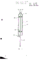
Fig. 1 is the longitudinal sectional drawing of first embodiment of the invention;
Fig. 2 is the longitudinal sectional drawing of second embodiment of the invention;
Fig. 3 is under the electrostatic interference condition, the distribution of relevant Fig. 1 embodiment electric field;
Fig. 4 is the schematic diagram of type lightning arrester shown in Figure 1;
The distribution of the highfield of relevant Fig. 1 embodiment when Fig. 5 approaches for lightning guide discharge;
Fig. 6 is under conditions of similarity, with the similar Electric Field Distribution that shows relevant franklin rod of figure;
Fig. 7 is the longitudinal sectional drawing of third embodiment of the invention;
Fig. 8 is the longitudinal sectional drawing of fourth embodiment of the invention.
Before beginning to be described in detail the embodiment of the invention, referring again to U.S. Pat-A-4 once, 518,816, first hurdle wherein particularly, the 14th row is to the 26th row.In this part of this patent specification, narrated the cutting edge of a knife or a sword edge of guide's discharge, this part is made up of charge particle, directly towards the earth.It is generally acknowledged near the strong electric field of generations the earth that approaches of this guide discharge, instead say it, it can produce head-on discharge or head on tracer or forward position part.This and the head-on discharge at first of meeting that causes discharging earlier can make " circuit " closure, and causes thunder discharge.Therefore, the benefit of its maximum is can closed circuit and absorb thunder discharge in one preferably on the position.
Fig. 1 shows a kind of concrete device 10 of lightning absorbing device of the present invention.Device 10 comprises an earth brace 12, it have 13, one conducting elements spherical in shape substantially 14 in an end by the supporter 16 of insulation attached on the above-mentioned earth brace.At the top of ball type device one looping pit 17 is arranged, be positioned at " arctic " position, between the end 13 of the edge in hole 17 and earth brace 12, form an air gap 18.One high impedance electrostatic releaser 20 is connected between element 14 and the bar 12.Although the end 13 of shown earth brace 12 is positioned on the surface continuity position of ball type device 14, it also can exceed this position and extend, near the position among perhaps being in the hole 17.
In Fig. 2, this concrete device 22 of lightning absorbing device comprises that also an earth brace 24, one annular conductive members 26 are connected on the earth brace 24 by insulation stent 28.Element 26 has the curvilinear surface of a complexity, and it is a bit as having the radially dish shape hemisphere of curved edge.Device 22 also has a common looping pit 29, between the end 25 of the edge in hole 29 and bar 24 air gap 32 is arranged.There is a high impedance electrostatic releaser 30 to be connected between element 26 and the bar 24.
Between embodiment that the present invention as can be seen narrated and the prior art franklin rod tangible difference is arranged, what promptly presented in the present invention is a level and smooth annular surface, rather than single or a plurality of end points.And, for the end 13,25 of bar 12,24, can be pointed, pancake, dish, hemisphere, convex, concave shape or other Any shape.
In addition, this system normally electrostatic and be designed to eliminate the corona radiation, this corona discharge is to produce under the condition of the highfield that this paper preface part is addressed, the thrust narrated of this and prior art is contradictory certainly.
Whether to studies show that of general lightning conductor system, for pointed end points, no matter have additional ion to produce in recent years, all may cause corona, it can form a space charge immediately on above-mentioned end points.This space charge has the polarity that can reduce described end electric field.
Laboratory and work place study shows, the intensity of electric field is critical parameters to the formation condition that the electron stream that is suitable for head-on discharging generates.The electron stream that developing into head-on discharge or tracer is very important and constituted the electric channel of connecting between cloud layer and the earth to stoping guide's discharge.
As mentioned above, space charge can weaken around the electric field that exposes end points.And fixed existing on the value of they is variable, and depends on the various factors as wind speed etc. to a great extent.The existence of space charge is proposition fails to hit franklin rod about thunder and lightning the repeatedly foundation of report.
According to the present invention, when the situation that does not have thunder and lightning to produce, this device is electrostatic.As mentioned above, surface 14 or 26 is to insulate mutually with its support bar 12 or 24, but is connected with it by a high-impedance network 20 or 30.Under common electrostatic field condition, above-mentioned surface and bar be ground connection effectively.The shape of whole assembly has been eliminated the generation of corona discharge, and this corona discharge can cause the formation of space charge.Fig. 3 shows under the electrostatic field condition electric field around Fig. 1 spherical.
Yet, thunder and lightning guide discharge near the time, this device is correspondingly made dynamic response by strengthening electric field and forming electric arc, with at the end of element conductive surface formation plasma.This plasma will produce the ideal conditions that forms electron stream with relevant field effect, and this electron stream promptly is converted into head-on discharge, and it can stop the guide to discharge.The present invention had before thunder and lightning is near near target other, the ability of flow of emitted electrons, thus have the desirable ability that absorbs thunder and lightning.
Fig. 4 illustrates two equivalent capacity C1 and C2, and when guide discharge approached, they were present between surface 14 and the bar 12, and is present in surface 14 and the guide discharges between 34, and its typical delivered charge is the 0.5-20 enclosed pasture in the time of 105/ millisecond.Owing to there is a high impedance 20 between bar 12 and the surface element 14, this element will make voltage rise.High impedance electrostatic releaser 20 has limited the flow at high speed of discharging current.
Between the end of ground connection support bar 12 and annular surface element 14, exist little air gap 18.When the part voltage of this outside insulation raises, in the air gap, form electric field.The geometry of this system has produced plasma or blockage effect (see figure 5) and formed a highfield immediately on the ground connection support bar.This is than stronger around the electric field strength of general franklin rod 36, and the situation of described Franklin 36 is shown in Figure 6.
If guide discharge is along 34 approaching sufficiently tight, and enough electric charges are arranged, will produce electric arc.The isoionic formation of electricity just triggers an electron stream that head-on discharges, and this electron stream has bigger transmission opportunity, and this is the space charge that disturbs in the above owing to not.
Lightning absorbing device of the present invention as can be seen probably produces initiating electron stream, head-on discharge or tracer, so thunder and lightning may be subjected to relative control action, thereby just towards this device, rather than towards the building that will protect.
Here very clear, if not for the reason of improving with respect to guide's discharge channel electric capacity, described conductive surface can adopt many difformities, as ellipse, and serve the tea holder shape or other adoptable shapes.The actual fixed electric capacity that provides between conductive surface element and earth brace also can be provided, can change the energy that is held in spark repetition rate and each spark.
Also spheroid can be cut apart in flakes similar some oranges.Cut apart every with earth brace and adjoin insulation mutually between each sheet.Each cutting plate all has the air gap of different size in this case.This method can produce electric arc and play fluctuation effect around bar.Therefore, the guide discharge near during, electric arc certainly will be persistent state.
In the conductor 38 in the drawings, there is support (ground connection) bar 40 and to be generally columniform conductive surface 42.A truncated cone end 44 is contained on this surface, between the edge of the end hole 45 44 and the end 41 of bar 40 air gap 46 is arranged.Insulation stent 48 is with insulation between insulating surface 42 and the bar 40.
Wherein also be provided with a static release device 50, be similar to the high impedance electrostatic releaser 30 in the applicable cases of earlier figures 2, in fact this device 50 can be positioned among the circular column 42 alternately.
Fig. 8 has illustrated the similar embodiment with Fig. 1, and except that label 13, all labels among Fig. 1 all indicate the same section among Fig. 8.
In Fig. 8, the end 52 of earth brace 12 is placed in the outside of spherical surface element 14, and its distance that is positioned at spherical surface 14 and bar 12 cross sections equals 25% of sphere diameter.Said as mentioned this end can be in any position between the distance shown in Fig. 1 and 8.Note also that in the end 52 have half spherical convex cross section.
Claims (9)
1, a kind of lightning absorbing device (10) comprises a continuous substantially surface element (14) and an earth element (12), it is characterized in that with insulate the mutually said surface element (14) of (16) of said earth element (12) be to be connected with said earth element (12) by a high impedance electrostatic releaser (20), define a air gap (18) between described surface element (14) and the last branch of described earth element (12) in one discontinuous section (17) on the said surface element (14), wherein between described surface element and described earth element, can produce electric arc under given conditions, this electric arc will cause isoionic generation and form head-on discharge
2,, it is characterized in that described surface element (14) is actually a sphere according to the device of claim 1.
3,, it is characterized in that described surface element (38) is actually one cylindrical according to the device of claim 1.
4,, it is characterized in that described surface element (26) is the radially butterfly hemisphere that has curved edge according to the device of claim 1.
5,, it is characterized in that described surface element (14) is partly to be made of several surface elements, and between every part surface element and described earth brace, have an air gap according to the device of claim 1.
6,, it is characterized in that described earth element (12) is an earth brace according to the device of claim 1.
7,, it is characterized in that described or each air gap (18) are present between the end (13) of described surface element (14) or each described surface element part and described earth brace according to claim 6 device.
8, according to the device of claim 1, it is characterized in that described earth element (12) is an earth brace, said part is the end (13) of earth brace, said end (13) are positioned near described discontinuous section (17).
9, according to the device of claim 1, it is characterized in that described earth element (12) is an earth brace, described part is the end (52) of earth brace, it is spherical that said surface element (14) is actually, hemisphere or cylindrical, said end (52) is to be positioned on such segment distance, promptly is 25% of described element diameter from the described discontinuous section distance to this end.
Applications Claiming Priority (5)
| Application Number | Priority Date | Filing Date | Title |
|---|---|---|---|
| AUPH398285 | 1985-12-19 | ||
| AUPH3982 | 1985-12-19 | ||
| AUPH752886 | 1986-08-15 | ||
| AUPH7528 | 1986-08-15 | ||
| AU66551/86A AU580698B2 (en) | 1985-12-19 | 1986-12-12 | Lightning conductor |
Publications (2)
| Publication Number | Publication Date |
|---|---|
| CN86108676A CN86108676A (en) | 1987-08-26 |
| CN1010150B true CN1010150B (en) | 1990-10-24 |
Family
ID=27155666
Family Applications (1)
| Application Number | Title | Priority Date | Filing Date |
|---|---|---|---|
| CN86108676.7A Expired CN1010150B (en) | 1985-12-19 | 1986-12-19 | Lightning conductor |
Country Status (6)
| Country | Link |
|---|---|
| EP (1) | EP0228984B1 (en) |
| CN (1) | CN1010150B (en) |
| AT (1) | ATE87141T1 (en) |
| DE (1) | DE3688056T2 (en) |
| ES (1) | ES2040703T3 (en) |
| IN (1) | IN168099B (en) |
Families Citing this family (14)
| Publication number | Priority date | Publication date | Assignee | Title |
|---|---|---|---|---|
| FR2697379B1 (en) * | 1992-10-28 | 1995-01-13 | Helita Sa | Lightning rod with electric discharge initiator sliding along a dielectric. |
| AU753280B2 (en) * | 1998-07-27 | 2002-10-17 | Erico International Corporation | Lightning air terminals and method of design and application |
| CN2456342Y (en) | 2000-12-28 | 2001-10-24 | 张世锭 | Device for amplifying and slow releasing electric charges in plasma lightning arresting technology |
| KR100653792B1 (en) | 2006-07-28 | 2006-12-05 | (주) 나라기술단 | Electric dipole streamer discharge type lightning rod |
| EP2084946A4 (en) * | 2006-10-24 | 2016-11-09 | Farouk A M Rizk | Lightning protection device: wet/dry field sensitive air terminal |
| FR2953337B1 (en) * | 2009-11-30 | 2012-01-06 | France Paratonnerres | CONTROLLED OPERATING PARATONNERRE |
| EP2712038A1 (en) * | 2012-09-25 | 2014-03-26 | Siemens Aktiengesellschaft | Guard electrode and line arrester with such a safety electrode |
| ES2537275B1 (en) | 2015-03-24 | 2016-02-12 | Dinnteco International, S.L. | Balancing device for variable electric fields |
| US10992111B2 (en) | 2016-10-21 | 2021-04-27 | Lightning Supression Systems Co., Ltd. | Lightning strike suppression type lightning protection device and lightning arrestor |
| CN106848845A (en) * | 2017-03-22 | 2017-06-13 | 宁夏顺和电工有限公司 | A kind of passive plasma drives thunder device |
| CN106848848A (en) * | 2017-03-22 | 2017-06-13 | 宁夏顺和电工有限公司 | A kind of integrated active and passive one plasma drive thunder device |
| CN108281006B (en) * | 2018-03-28 | 2020-11-06 | 浙江南自建设集团股份有限公司 | Visual vehicle tracking system based on license plate identification |
| CN108832584B (en) * | 2018-09-12 | 2019-12-06 | 安徽仁信电子工程有限公司 | Lightning protection device for shore-based radar |
| DE102019101577A1 (en) * | 2019-01-23 | 2020-07-23 | OBO Bettermann Hungary Kft. | Lightning current arrester |
Family Cites Families (4)
| Publication number | Priority date | Publication date | Assignee | Title |
|---|---|---|---|---|
| FR1203579A (en) * | 1958-03-17 | 1960-01-20 | Training in lightning rods | |
| FR1478526A (en) * | 1966-03-11 | 1967-04-28 | Gen Prot Establishment | Lightning rod with high ionizing power |
| US4480146A (en) * | 1982-06-03 | 1984-10-30 | Energie Froide International Sa | Lightning protector assembly |
| ES526264A0 (en) * | 1983-09-19 | 1984-07-01 | Illa Arnau Angel | IMPROVEMENTS IN THE CONSTRUCTION OF LIGHTNING RODS |
-
1986
- 1986-12-11 AT AT86630187T patent/ATE87141T1/en not_active IP Right Cessation
- 1986-12-11 EP EP86630187A patent/EP0228984B1/en not_active Expired - Lifetime
- 1986-12-11 DE DE8686630187T patent/DE3688056T2/en not_active Expired - Lifetime
- 1986-12-11 ES ES198686630187T patent/ES2040703T3/en not_active Expired - Lifetime
- 1986-12-18 IN IN989/MAS/86A patent/IN168099B/en unknown
- 1986-12-19 CN CN86108676.7A patent/CN1010150B/en not_active Expired
Also Published As
| Publication number | Publication date |
|---|---|
| CN86108676A (en) | 1987-08-26 |
| ATE87141T1 (en) | 1993-04-15 |
| EP0228984B1 (en) | 1993-03-17 |
| EP0228984A2 (en) | 1987-07-15 |
| DE3688056T2 (en) | 1993-07-15 |
| IN168099B (en) | 1991-02-02 |
| DE3688056D1 (en) | 1993-04-22 |
| EP0228984A3 (en) | 1988-11-09 |
| ES2040703T3 (en) | 1993-11-01 |
Similar Documents
| Publication | Publication Date | Title |
|---|---|---|
| AU2020200901B2 (en) | Passive compound strong-ionization discharging plasma lightning rejection device | |
| CN1010150B (en) | Lightning conductor | |
| CN101611655B (en) | Lightning protection device: wet/dry field sensitive air terminal | |
| US6320119B1 (en) | Lightning air terminals and method of design and application | |
| US4760213A (en) | Lightning conductor | |
| JP2886062B2 (en) | lightning rod | |
| CN211238810U (en) | Coulomb force traction recoil intermittent interruption arc lightning rod | |
| US6069314A (en) | Emitter of ions for a lightning rod with a parabolic reflector | |
| US4565900A (en) | Lightning rod construction | |
| CN108963767A (en) | A kind of corona field drives thunder device and its drives thunder method | |
| CN106593787B (en) | Lightning protection device for movable or fixed object | |
| CA1191913A (en) | Vertically aligned gas-insulated transmission line having particle traps at the inner conductor | |
| Watson et al. | Impulse flashover trajectory in air in nonuniform fields | |
| Safıyev et al. | Analysis of the application of active lightning rods in lightning protection objects | |
| EP0150855A2 (en) | Ionizing lightning conductor | |
| JP3433004B2 (en) | DC gas insulated busbar | |
| JPS5956399A (en) | Arrester for ionizing by corona action | |
| WO2023248333A1 (en) | Lightning conduction device | |
| CN110570999A (en) | single-recoil arc-extinguishing device and method | |
| Qiu et al. | Lightning strike protection performance research of early streamer emission terminal based on contrastive discharge test | |
| AU670360B2 (en) | Improvements in lightning protection | |
| US4085376A (en) | Device for electrical deceleration of flow of charged particles | |
| RU2336617C2 (en) | Lightning-arrester with accelerated air ionisation | |
| CN212114295U (en) | Direct-lightning-strike prevention device for radar | |
| CA1071770A (en) | Device for electrical deceleration of flow of charged particles |
Legal Events
| Date | Code | Title | Description |
|---|---|---|---|
| C06 | Publication | ||
| PB01 | Publication | ||
| C10 | Entry into substantive examination | ||
| SE01 | Entry into force of request for substantive examination | ||
| C13 | Decision | ||
| GR02 | Examined patent application | ||
| C14 | Grant of patent or utility model | ||
| GR01 | Patent grant | ||
| C53 | Correction of patent of invention or patent application | ||
| COR | Change of bibliographic data |
Free format text: CORRECT: PATENTEE; FROM: JOHN RICHARD GANGLI TO: PERSEUS PROTEOMICS CO., LTD. Free format text: CORRECT: PATENTEE; FROM: PERSEUS PROTEOMICS CO., LTD. TO: AIRIK LIGHTNING PROTECTION TECHNOLOGY PRIVATE CO., LTD. |
|
| CP01 | Change in the name or title of a patent holder |
Patentee after: ERICO Lightning Protection Technology Co.,Ltd. Patentee before: Global lightning protection Technology Pte. Ltd. Patentee after: Global lightning protection Technology Pte. Ltd. Patentee before: John Richard Guli |
|
| C15 | Extension of patent right duration from 15 to 20 years for appl. with date before 31.12.1992 and still valid on 11.12.2001 (patent law change 1993) | ||
| OR01 | Other related matters | ||
| C17 | Cessation of patent right | ||
| CX01 | Expiry of patent term |