CN1009748B - Ratio valve to control unloading of modulating relief valve - Google Patents
Ratio valve to control unloading of modulating relief valveInfo
- Publication number
- CN1009748B CN1009748B CN87106712A CN87106712A CN1009748B CN 1009748 B CN1009748 B CN 1009748B CN 87106712 A CN87106712 A CN 87106712A CN 87106712 A CN87106712 A CN 87106712A CN 1009748 B CN1009748 B CN 1009748B
- Authority
- CN
- China
- Prior art keywords
- valve
- pressure
- hole
- communicated
- clutch
- Prior art date
- Legal status (The legal status is an assumption and is not a legal conclusion. Google has not performed a legal analysis and makes no representation as to the accuracy of the status listed.)
- Expired
Links
Images

Classifications
-
- F—MECHANICAL ENGINEERING; LIGHTING; HEATING; WEAPONS; BLASTING
- F16—ENGINEERING ELEMENTS AND UNITS; GENERAL MEASURES FOR PRODUCING AND MAINTAINING EFFECTIVE FUNCTIONING OF MACHINES OR INSTALLATIONS; THERMAL INSULATION IN GENERAL
- F16D—COUPLINGS FOR TRANSMITTING ROTATION; CLUTCHES; BRAKES
- F16D48/00—External control of clutches
- F16D48/02—Control by fluid pressure
- F16D48/0206—Control by fluid pressure in a system with a plurality of fluid-actuated clutches
-
- F—MECHANICAL ENGINEERING; LIGHTING; HEATING; WEAPONS; BLASTING
- F02—COMBUSTION ENGINES; HOT-GAS OR COMBUSTION-PRODUCT ENGINE PLANTS
- F02M—SUPPLYING COMBUSTION ENGINES IN GENERAL WITH COMBUSTIBLE MIXTURES OR CONSTITUENTS THEREOF
- F02M61/00—Fuel-injectors not provided for in groups F02M39/00 - F02M57/00 or F02M67/00
- F02M61/16—Details not provided for in, or of interest apart from, the apparatus of groups F02M61/02 - F02M61/14
- F02M61/166—Selection of particular materials
-
- F—MECHANICAL ENGINEERING; LIGHTING; HEATING; WEAPONS; BLASTING
- F02—COMBUSTION ENGINES; HOT-GAS OR COMBUSTION-PRODUCT ENGINE PLANTS
- F02M—SUPPLYING COMBUSTION ENGINES IN GENERAL WITH COMBUSTIBLE MIXTURES OR CONSTITUENTS THEREOF
- F02M61/00—Fuel-injectors not provided for in groups F02M39/00 - F02M57/00 or F02M67/00
- F02M61/16—Details not provided for in, or of interest apart from, the apparatus of groups F02M61/02 - F02M61/14
- F02M61/168—Assembling; Disassembling; Manufacturing; Adjusting
-
- F—MECHANICAL ENGINEERING; LIGHTING; HEATING; WEAPONS; BLASTING
- F02—COMBUSTION ENGINES; HOT-GAS OR COMBUSTION-PRODUCT ENGINE PLANTS
- F02M—SUPPLYING COMBUSTION ENGINES IN GENERAL WITH COMBUSTIBLE MIXTURES OR CONSTITUENTS THEREOF
- F02M61/00—Fuel-injectors not provided for in groups F02M39/00 - F02M57/00 or F02M67/00
- F02M61/16—Details not provided for in, or of interest apart from, the apparatus of groups F02M61/02 - F02M61/14
- F02M61/18—Injection nozzles, e.g. having valve seats; Details of valve member seated ends, not otherwise provided for
-
- F—MECHANICAL ENGINEERING; LIGHTING; HEATING; WEAPONS; BLASTING
- F16—ENGINEERING ELEMENTS AND UNITS; GENERAL MEASURES FOR PRODUCING AND MAINTAINING EFFECTIVE FUNCTIONING OF MACHINES OR INSTALLATIONS; THERMAL INSULATION IN GENERAL
- F16D—COUPLINGS FOR TRANSMITTING ROTATION; CLUTCHES; BRAKES
- F16D48/00—External control of clutches
- F16D48/02—Control by fluid pressure
- F16D48/04—Control by fluid pressure providing power assistance
-
- F—MECHANICAL ENGINEERING; LIGHTING; HEATING; WEAPONS; BLASTING
- F16—ENGINEERING ELEMENTS AND UNITS; GENERAL MEASURES FOR PRODUCING AND MAINTAINING EFFECTIVE FUNCTIONING OF MACHINES OR INSTALLATIONS; THERMAL INSULATION IN GENERAL
- F16D—COUPLINGS FOR TRANSMITTING ROTATION; CLUTCHES; BRAKES
- F16D48/00—External control of clutches
- F16D48/02—Control by fluid pressure
- F16D2048/0224—Details of conduits, connectors or the adaptors therefor specially adapted for clutch control
-
- F—MECHANICAL ENGINEERING; LIGHTING; HEATING; WEAPONS; BLASTING
- F16—ENGINEERING ELEMENTS AND UNITS; GENERAL MEASURES FOR PRODUCING AND MAINTAINING EFFECTIVE FUNCTIONING OF MACHINES OR INSTALLATIONS; THERMAL INSULATION IN GENERAL
- F16D—COUPLINGS FOR TRANSMITTING ROTATION; CLUTCHES; BRAKES
- F16D48/00—External control of clutches
- F16D48/02—Control by fluid pressure
- F16D2048/0227—Source of pressure producing the clutch engagement or disengagement action within a circuit; Means for initiating command action in power assisted devices
- F16D2048/0233—Source of pressure producing the clutch engagement or disengagement action within a circuit; Means for initiating command action in power assisted devices by rotary pump actuation
- F16D2048/0251—Electric motor driving a piston, e.g. for actuating the master cylinder
-
- F—MECHANICAL ENGINEERING; LIGHTING; HEATING; WEAPONS; BLASTING
- F16—ENGINEERING ELEMENTS AND UNITS; GENERAL MEASURES FOR PRODUCING AND MAINTAINING EFFECTIVE FUNCTIONING OF MACHINES OR INSTALLATIONS; THERMAL INSULATION IN GENERAL
- F16D—COUPLINGS FOR TRANSMITTING ROTATION; CLUTCHES; BRAKES
- F16D48/00—External control of clutches
- F16D48/02—Control by fluid pressure
- F16D2048/0257—Hydraulic circuit layouts, i.e. details of hydraulic circuit elements or the arrangement thereof
- F16D2048/0272—Two valves, where one valve is supplying fluid to the cylinder and the other valve is for draining fluid to the sump
-
- Y—GENERAL TAGGING OF NEW TECHNOLOGICAL DEVELOPMENTS; GENERAL TAGGING OF CROSS-SECTIONAL TECHNOLOGIES SPANNING OVER SEVERAL SECTIONS OF THE IPC; TECHNICAL SUBJECTS COVERED BY FORMER USPC CROSS-REFERENCE ART COLLECTIONS [XRACs] AND DIGESTS
- Y10—TECHNICAL SUBJECTS COVERED BY FORMER USPC
- Y10T—TECHNICAL SUBJECTS COVERED BY FORMER US CLASSIFICATION
- Y10T29/00—Metal working
- Y10T29/49—Method of mechanical manufacture
- Y10T29/49229—Prime mover or fluid pump making
- Y10T29/49298—Poppet or I.C. engine valve or valve seat making
- Y10T29/49306—Valve seat making
-
- Y—GENERAL TAGGING OF NEW TECHNOLOGICAL DEVELOPMENTS; GENERAL TAGGING OF CROSS-SECTIONAL TECHNOLOGIES SPANNING OVER SEVERAL SECTIONS OF THE IPC; TECHNICAL SUBJECTS COVERED BY FORMER USPC CROSS-REFERENCE ART COLLECTIONS [XRACs] AND DIGESTS
- Y10—TECHNICAL SUBJECTS COVERED BY FORMER USPC
- Y10T—TECHNICAL SUBJECTS COVERED BY FORMER US CLASSIFICATION
- Y10T29/00—Metal working
- Y10T29/49—Method of mechanical manufacture
- Y10T29/49428—Gas and water specific plumbing component making
- Y10T29/49432—Nozzle making
Abstract
A modulating pressure relief valve for aiding the clutch in smooth clutch engagement, wherein, a ratio valve mechanism is located within the valve spool of the modulating pressure relief valve thus providing a simple and compact valve mechanism which reduces the total system size and further eliminates additional conduits and/or lines. In this arrangement, in order to ensure that the load piston is fully reset, a mechanism is provided which establishes a ratio between the pressure of the fluid being directed to the clutch and the pressure of the fluid acting on the load piston of the modulating pressure relief valve so that the pressurized fluid acting on the load piston during the filling of the clutch is vented to the reservoir to reset the load piston even though the pressure of the fluid available to the clutch is still at a higher pressure level.
Description
The present invention is broadly directed to a kind of fluid system with adjustable relief valve, and this adjustable relief valve can be used to control the speed that the pressure of hydraulic actuator raises.The present invention be more particularly directed to a kind of Proportional valve that is used for controlling the adjustable relief valve off-load, so that the load piston of adjustable relief valve is resetted fully before to the hydraulic actuator pressurization.
In fluid system, for example have in the transmission device of clutch of hydraulic actuating and exist a problem, that is exactly to manage to guarantee that the load piston in the adjustable relief valve resets before relevant clutch begins to engage fully.This problem relates generally to such fact, and system pressure does not have time enough to descend before each clutch is begun once more by application of load and clutch.Therefore when load piston did not also reset fully, the higher pressure in the system can produce the rapid joint of clutch, and this life-span for other relevant parts of clutch and transmission device is harmful to.
Therefore the system that provides a kind of energy proof load piston to reset fully is useful.In addition, in order to control overall cost, this system structurally should be simple.
The various transmission devices of Shi Yonging are also thought to address the above problem as much as possible in the past.A kind of such transmission device is published in U. S. Patent 3,566, and on 716, this patent right is presented to P.K. on March 2nd, 1971 and looks into Trajet.This patent has been said a kind of control system, and this control system is used to have the transmission device of direction and speed clutch.In this transmission device, the direction clutch is soon by application of load and pressurization, and speed clutch is then thereafter more slowly by application of load and pressurization.The load piston in this transmission device during at direction clutch application of load and the pressure source of system isolate, and when the speed clutch application of load, open system's supply pressure.When clutch breaks away from and another clutch when engaging then, load piston moves, and tends to zero load situation.In this device, this moving is by controlling in the size of damping hole on the load piston, between load piston pressure chamber and system's fuel tank.If damping hole is too big, the speed that pressure raises will be very slow, if the speed that the less pilot pressure preferably of damping hole raises, but load piston can not reset rapidly.This system need properly solve the speed that pressure raises and can make relation between the speed that load piston resets.
The U. S. Patent 3,799,308 that was presented to the E.R. Erisman on March 26th, 1974 has been said a kind of control system that is used to have the transmission device of direction and speed clutch.This system comprises that one has the adjusting reduction valve of a load piston, and this load piston can be controlled the speed that the pressure in the clutch actuator raises when each clutch.In this device, load piston has only when clutch actuator pressure and drops to a low pressure, resets as 30 pounds of/square inch (Psi) Shi Caihui.Because load piston is direct and the pressure communication of clutch actuator, just need make two pressure reduce to low pressure soon.But the pressure in clutch actuator tends to descend with slower speed, because this decline directly is proportional to the speed that clutch loads.This has just stoped, and load piston reaches the ability that resets fully before clutch loads and engages beginning.The result causes clutch to engage sharp.
4,046,160 the U. S. Patent of being numbered on September 6th, 1977 promulgation, Alfred Jochim Huo Siqi has been said a kind of control system that is used to have the transmission device of direction and speed clutch.This system also comprises a load piston that is used for pilot pressure rising speed when relevant clutch.This device also comprises a separator piston, this piston in transmission device direction and can respond the opening of the quick exhaust duct of pressure control in direction clutch and the speed clutch during rapid change so that load piston is resetted fast.Separator piston in this device plays differential valve, so that set up than at the higher application of load pressure in the direction clutch of the application of load pressure in the speed clutch.For load piston is resetted fast, the pressure in the system must be reduced to the pressure rating of direction clutch application of load pressure.Therefore, clutch may be by application of load before system pressure drops to the level that needs, and the result is that load piston can not reset before clutch begins to engage fully.This just causes rapid or jiggly clutch usually.
On January 2nd, 1979 promulgation, P.K. look into Trajet, be numbered 4,132,302 U. S. Patent and said a kind of control system that is used to have the transmission device of direction and speed clutch.This system comprises that one is controlled at the load piston of the speed of the pressure rising in each clutch actuator.This device also comprises another piston, and this piston can automatically make the load piston pressure chamber communicate with floss hole, so that the pressure in the response clutch actuator resets load piston fast.In this device, the pressure in the clutch actuator must drop to and the identical level of clutch application of load pressure, so that another piston responds soon and load piston is resetted.Like this, if before system pressure reduces to desired pressure application of load, load piston just can not reset fully, thereby with top the same, also can cause the rapid joint of clutch.
The present invention is in order to solve problem recited above.
The purpose of this invention is to provide a kind of valve member that comprises the Proportional valve that is used for controlling the adjustable relief valve off-load, the load piston of adjustable relief valve is resetted before to the hydraulic actuator pressurization fully, thereby avoid the violent joint of clutch.
For realizing this purpose, valve member of the present invention comprises in the housing a single hole, an import, and control mouth and many floss holes, these floss holes laterally pass through single hole respectively with the relation of axially spaced-apart.Load piston is slidably mounted in the single hole of housing; And a valve part also is slidably mounted in the single hole, and contiguous load piston, and this valve part can move between the primary importance and the second place, and in primary importance, the path between in import and the many floss holes is plugged; Above-mentioned one in second place import and many floss holes is communicated with.One end of valve part has a blind hole, and its periphery has an annular groove.One passage is arranged on the valve part, and it makes blind hole and annular groove on the valve part, and the another one floss hole of many floss holes is communicated with.Valve part also has in addition a passage, and this passage makes the blind hole on the valve part be communicated with control mouth on the housing; And in single hole, between load piston and valve part, form a pressure chamber.One Proportional valve parts are slidingly mounted in the blind hole of valve part, and can move between the primary importance and the second place.In primary importance, between passage in the valve part, that at first mention and pressure chamber, be plugged, in the second place, the passage of at first mentioning is communicated with the pressure chamber.One that be communicated with the pressure chamber, predetermined water cross section is arranged on the Proportional valve parts, also have one by another passage on the valve part, a continuation and control mouthful less water cross section that is communicated with.
Valve member of the present invention is applicable to a kind of fluid system of transmission device, this system has a fluid pressure source, one fuel tank, one is used for accepting the power transmission device of the fluid from described fluid pressure source, an and selector valve that is connected between fluid pressure source and the power transmission device, during the action of this selector valve, carry the fluid that comes from fluid pressure source to remove filling and plus-pressure conveying means selectively, or be discharged in the fuel tank from power transmission device and go.Adjustable relief valve has a valve part and a load piston that can move between an essentially no load position and a load position, this adjustable relief valve is connected on fluid pressure source and the power transmission device.Adjustable relief valve is used for controlling the speed of the pressure rising that is transported to the fluid that goes in the power transmission device.Also have parts to be used at the pressure of the fluid that flows to power transmission device and to act between the pressure of the fluid on the load piston of adjustable relief valve set up proportionate relationship, like this when the power transmission device application of load, acting on pressurized stream physical efficiency on the load piston is discharged in the fuel tank and goes, so that load piston resets to uncharge basically position, even the pressure of the fluid in the power transmission device temporarily still is on the high-pressure horizontal.
When valve member of the present invention is used for the fluid system of transmission device, provide a kind of control, made load piston can be secured at when in the transmission device direction and velocity variations taking place and reset fully load piston.The Proportional valve parts are at the hydrodynamic pressure that is fed to power transmission device or clutch and act between the hydrodynamic pressure on the load piston ratio is provided.Like this, even the pressure in power transmission device temporarily still is in higher stress level, the pressure flow physical efficiency that acts on the load piston is discharged in the fuel tank, so that load piston is resetted fully.This device allows load piston not resetted fully when system pressure is reduced to the pressure that acts on load piston as yet, and in the system in prior art, the pressure that acts on the load piston is the same with pressure in the system.Because the pressure that acts on the piston is discharged, main overflow guiding valve opens wide with releasing system pressure, has just no longer included any hydrodynamic pressure like this in the load piston chamber.
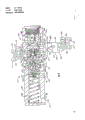
Fig. 1 is a local simple diagram that comprises the fluid system of one embodiment of the invention;
Fig. 2 is the local simple diagram of fluid system in a kind of operating condition shown in Figure 1;
Fig. 3 is the running pressure of expression fluid means shown in Figure 1 and the plotted curve of the relation between the time.
Referring now to accompanying drawing,, especially referring to Fig. 1 and Fig. 2, shown fluid system 10 is used for the vehicle (not shown), be used for controlling selectively many power transmission devices, for example speed clutch 12,14 and direction clutch 16,18 joint and disengaging, and the speed of control pressure rising wherein.
Fluid system comprises a fluid pressure source, as pump 20, is used for aspirating by the fluid of pipeline 24 from fuel tank 22.Speed and directional selecting valve 26,28 are communicated with pump 20 by flow pipeline 30,32,34. Pipeline 36,38 makes speed clutch 12 and 14 be communicated with speed selection valve 26 respectively, and pipeline 40,42 makes direction clutch 16 and 18 be communicated with directional selecting valve 28 respectively.Selector valve 26 and 28 is communicated with fuel tank 22 by pipeline 44 and 46 respectively.
One valve part is slidably mounted in 58 li of the single holes of housing 56 as guiding valve 80.Valve part 80 forms a blind hole 82, the first and second passages 84 and 86 at the one end connects blind hole 82 and single hole 58.The mutual axially spaced-apart of first and second passages.Annular groove 88 is formed on the periphery of guiding valve 80, and first passage 84 communicates with annular groove 88.Another blind hole 90 is positioned at the other end of guiding valve 80.Second annular groove 92 is positioned on the periphery of guiding valve 80, and has a passage 94, passage 94 that blind hole 90 and annular groove 92 are connected on guiding valve 80 in addition.First annular groove 88 also is communicated with floss hole 72, and second annular groove 92 also is communicated with import 60, and is communicated with floss hole 68 selectively.Fuse 96 is slidably mounted in 90 li of second blind holes, and forms a pressure chamber 98 between an end of the bottom of blind hole 90 and fuse 96.Load piston 100 is slidably mounted on 58 li of single holes, and contiguous guiding valve 80, forms a pressure chamber 102 thus between the load piston 100 of 58 li of single holes and guiding valve 80.Spring 104 is positioned at 58 li of single holes, it and load piston dorsad a side contacts of pressure chamber 102, and bias voltage load piston 100 towards primary importance.Load piston 100 can move to the second place when 102 li pressure increased when the pressure chamber, and biasing spring 104 conversely.
Relief valve 108 is installed in 100 li of load piston, and its effect is the pressure maximum of placing restrictions on 102 li of pressure chambers.Relief valve 108 comprises valve seat 110, and the steel ball 112 that contacts with valve seat 110, an and bias voltage steel ball usually is to the spring 114 of closed position.
It is in order to flow to power transmission device 12,14 that parts 120 are provided, the pressure of 16,18 fluid and act between the pressure of fluid of load piston 100 of 50 li of adjustable relief valves and form a ratio.Parts 120 are slidingly mounted at 82 li of blind holes, and by latch 122 it are stayed wherein.Parts 120 comprise the Proportional valve parts 124 that can move between the primary importance and the second place.Proportional valve parts 124 comprise that one is slidably mounted on the valve parts 126 of 82 li of the blind holes of guiding valve 80, and valve parts 126 has a first end 128, one the second ends 130 and an intermediate portion 132.Hole 134 is positioned at 126 li of valve partses, and annular groove 136 is positioned at its periphery, and communicates with hole 134 by passage 138.Throttling passage is positioned at the second end 130 of valve parts 126 as damping hole 140, and is close to pressure chamber 102.Fuse 142 is slidably mounted on 134 li in the hole of first end 128, and the hole between damping hole 140 and fuse 142 forms a pressure chamber 144 for 134 li.The second end 130 of contiguous pressure chamber 102 has a predetermined cross section, and the cross section of the fuse 142 of 144 li of pressure chambers is less.
Fig. 3 has represented a typical pressure diagram, this curve representation clutch load and and then the pressure of the inside increase and when making direction and/or rapid change each stress level and time relation in speed and the direction clutch.Pressure in the solid line 146 expression speed clutch is from a bit (fluid in this clutch is by dump, filling), and stress level is increased to peaked situation by the climbing speed of control then.Dotted line 148 is illustrated in fluid in the direction clutch equally by the pressure in dump, when filling and the pressure that controllably increases then.
Should be realized that under the situation that does not break away from essence of the present invention, fluid system 10 can have different shape.For example, ratio determines that parts 120 can be positioned at one and separate in the housing.In addition, flow pipeline 34 does not need the housing 56 through adjustable relief valve 50.Flow pipeline 34 parts in damping hole 54 downstreams can directly be communicated with selector valve 28, and another pipeline can make control mouthfuls 62 be communicated with flow pipeline 34, has saved like this and has exported 64.In relative assembly, have integer ratio and determine that the adjustable relief valve of parts forms an adjustable relief valve assembly.
Say that below it is in industrial Applicable scope:
When fluid system is in as shown in Figure 1 neutral gear situation, be sent to 26 li on speed selection valve from the pressure fluid of pump 20 by pipeline 30 and 32, be sent to directional selecting valve 28 by flow pipeline 34 and the damping hole 52,54 on it simultaneously.Flow pipeline 34 also flows to pressure fluid the import 60 of adjustable relief valve 50.Because fluid system 10 is in the neutral gear situation, adjustable relief valve 50 remains on its maximum pressure levels system pressure at import 60 places.Any liquid stream that surpasses controllably is sent to floss hole 68 shuntings by moving of guiding valve 80.Guiding valve 80 can move between the primary importance and the second place, and in primary importance, guiding valve 80 is blocked the connection of fluid between import 60 and floss hole 68; In the second place, import 60 is communicated with floss hole 68 by annular groove 92.Constantly communicate by annular groove 92 and passage 94 from the pressure fluid of pump 20 with pressure chamber 98.Act on fuse 96 and blind hole 90 bottoms, 98 li of pressure chambers are in the second place of pressure fluid biased spool valve 80 towards it, thereby the fluid of 60 li of imports is communicated with floss hole 68.
Simultaneously, be sent to control mouthfuls 62 by flow pipeline 34 and the damping hole 54 on it from the pressure fluid of pump 20, then by passage 86, annular groove 136, passage 138, pressure chamber 144 and damping hole 140 are sent to pressure chamber 102.Act on guiding valve 80 1 ends 102 li of pressure chambers hydrodynamic pressure with the opposite direction biased spool valve 80 of power of the pressure fluid of 98 li of pressure chambers.In addition, the pressure fluid that the pressure chamber is 102 li acts on an end of load piston 100, makes load piston shift to the second place of shown in Figure 1 it from its primary importance, with the bias voltage of antagonism spring 104.When load piston 100 arrival position shown in Figure 1,102 pressure fluid controllably is diverted to 22 li of fuel tanks by floss hole 74 from the pressure chamber, so that keep-up pressure the 102 li predetermined maximum pressure levels in chamber.In the system of a standard, the stress level that the pressure chamber the is 98 li almost pressure of 102 li of specific pressure chambers is big 4 times.Because pressure balance, guiding valve 80 is in position as shown in Figure 1 basically, on this position, controllably is diverted to 22 li of fuel tanks from the pressure fluid of pump 20 by floss hole 68, so that system pressure is remained on the highest level.
The valve parts 126 of Proportional valve parts 124 can move between as shown in Figure 1 the primary importance and the second place, and is in primary importance, blocked between pressure chamber 102 and the floss hole 72; In the second place, pressure chamber 102 is communicated with floss hole 72 by passage 84 and annular groove 88.Valve parts 126 response of Proportional valve parts 124 acts on the pressure fluid of 144 li of pressure chambers on the fuse 142 and biased towards primary importance, and 102 li of response pressure chambers are at pressure fluid and biased towards the second place.When 102 li hydrodynamic pressure surpassed predetermined value of pressure with respect to 144 li of pressure chambers when the pressure chamber, valve parts 126 was shifted to the second place.In relative assembly, the stress level of the fluid that the pressure chamber the is 144 li almost stress level of 102 li of specific pressure chambers is big 3 times, so that valve parts 126 is remained on its primary importance.
Fig. 2 has represented the running of fluid system 10 when directional selecting valve 28 and speed selection valve 26 are in a kind of drive manner.Because to direction clutch 16 and speed clutch 12 application of loads, be in illustrated running state, drop to a very low level at the hydrodynamic pressure of 30,32,34 li in flow pipeline, know as the curve of Fig. 3 bottom and represent.
In order to limit the rapid joint of clutch, need to reduce the stress level of the fluid in the clutch that is in disengaged position, and reduce soon and act on hydrodynamic pressure on the load piston 100,102 li of pressure chambers, like this, load piston can just reset fully by application of load with before beginning to engage.In relative assembly, owing to the hydrodynamic pressure reduction of 144 li of pressure chambers, the stress level that the pressure chamber is 102 li reduces with a slower ratio, because it is initially located in lower stress level, so throttling passage 140 has stoped the possibility of the very fast reduction of stress level.Ratio when the pressure chamber between the stress level of 102 li of 144 li stress level and pressure chambers drops to 3: 1 when following, and valve parts 126 moves to the right side shown in the figure, and pressure chamber 102 is communicated with floss hole 72.At this moment, the pressure fluid that the pressure chamber is 102 li drops to low-down level very soon, thereby allows load piston 100 to reset to position shown in Figure 2 fully.Even above-mentioned resetting still also can take place in the stress level that the pressure chamber is 144 li on higher stress level.Simultaneously, valve part 80 is moved to the left, and as shown in Figure 2, allows to be communicated with between import 60 and the floss hole 68, so that reduce system pressure soon.Valve part 80 be moved to the left be because the power of 98 li formation in the pressure chamber now greater than the resistivity of 102 li of pressure chambers.So load piston 100, or is just resetted by application of load with when beginning to engage before this fully at each clutch.
Behind the clutch application of load, being increased like that shown in the solid line of Fig. 3 and dotted line of the stress level in relevant speed and the direction clutch.The hydrodynamic pressure of speed clutch 12 is increased to a low pressure of setting up very soon from low load pressure in safety valve, and the stress level of 16 li on direction clutch still maintains on the lower load pressure level.This mainly is owing to the flow resistance of passing damping hole 52 is caused to the living pressure difference of liquid miscarriage.This pressure difference between speed clutch and the direction clutch is directly proportional with the size of damping hole 52.Solid line 146 is a flat part in the back that pressure increases fast, and its expression was finished the needed time of direction clutch 16 application of loads.The dotted line 148 corresponding flat parts that are parallel to above-mentioned solid line 146 are illustrated in the last application of load of any increase generation the place ahead of pressure to clutch.Solid line to vertical transformation represents direction clutch be coupled with load suddenly with dotted line from flat.Stress level increases to a bit fast then, and at this point, guiding valve 80 is in fluid branch stream mode, and load piston 100 begins to move so that the level of the bias voltage of antagonism spring 104 and the stress level of 102 li of pressure chambers is in.At this point, the speed that pressure raises is controlled by the mobile of bias voltage of load piston 100 antagonism springs 104, and is represented as the slope of a curve on Fig. 3.And not being both between the represented pressure of two curves on Fig. 3 controlled by the size of damping hole 52, the angle that tilts is the power by spring 104, and the relation between the active area of the fuse 96 of the active area of an end of the safe guiding valve 80 of contiguous pressure chamber 102 and contiguous pressure chamber 98 is controlled.
When load piston 100 arrives position shown in Figure 1, each clutch reaches maximum stress level, and is keeping therein, as Fig. 3 shown in the flat part.This stress level is maintained in relevant speed and the direction clutch, and unnecessary unwanted fluid is discharged in the fuel tank from floss hole 68 and goes then by opening 60 and be diverted to annular groove 92.
Above-mentioned fluid system and ratio determine that parts combine and form a device, can the proof load piston when the clutch application of load, also can reset fully even the stress level in the fluid system descends with lower speed.This device has been eliminated the possibility that clutch begins to engage on higher stress level, and this joint can produce strong impact to the parts of system.In addition, this relation provides a kind of small and exquisite device, and this device structurally is simple, and only need utilize easy production technology.
On the other hand, objects and advantages of the present invention can obtain from the analysis and research to accompanying drawing, explanation and attached claim.
Claims (3)
1, a kind of valve member that is used for fluid system comprises:
One housing has a single hole, an import, a control mouth and many drain opening that connects single hole on axially-spaced locations;
One is slidably mounted on the load piston in the single hole;
One is slidably mounted on the valve part in the single hole of contiguous load piston, this valve part can move between the primary importance and the second place, in primary importance, be plugged between one in import and the many floss holes, in the second place, be communicated with between import and this floss hole, an end of described valve part has a blind hole, also has a passage that the blind hole on the valve part is communicated with control mouth on the housing on the valve part;
The other end of described valve part one second blind hole arranged with a fuse that is positioned at slidably among second blind hole, in the bottom of second blind hole in the valve part with place between the fuse of this blind hole and form a pressure chamber, described pressure chamber can accept the pressure fluid from fluid pressure source, and bias valve door part antagonism spring.
One be formed in the single hole, the pressure chamber between load piston and the valve part;
It is characterized in that:
The periphery of valve part has an annular groove, have on the valve part one make on the valve part blind hole with its on annular groove and another passage of being communicated with of the another one in many floss holes.
One places the Proportional valve parts in the blind hole of valve part slidably, and it can move between the primary importance and the second place.In primary importance, being communicated with between the pressure chamber in described another passage in the valve part and the single hole is plugged; In the second place, the passage of at first mentioning is communicated with pressure chamber in the single hole.Described Proportional valve parts have that be communicated with pressure chamber in the single hole, a predetermined water cross section and by a passage of at first mentioning in the valve part and the control mouthful less water cross section that maintenance is communicated with.
2, valve member according to claim 1 is characterized in that, the Proportional valve parts comprise a valve parts and a fuse.Described valve parts has a first end and a second end, at first end one hole is arranged, and described fuse is slidably mounted in this hole.One throttling passage that the hole in the valve parts is communicated with the second end is arranged in the valve parts, form described predetermined water cross section by the second end of valve parts, and form less water cross section by the end of the fuse in the hole that places valve parts.
3, valve member according to claim 2 is characterized in that, the periphery of valve parts also has an annular groove, and a passage that the hole of the valve parts of contiguous throttling passage is communicated with annular groove is arranged in the valve parts.
Applications Claiming Priority (2)
| Application Number | Priority Date | Filing Date | Title |
|---|---|---|---|
| US914,974 | 1986-10-03 | ||
| US06/914,974 US4751866A (en) | 1986-10-03 | 1986-10-03 | Ratio valve to control unloading of modulating relief valve |
Publications (2)
| Publication Number | Publication Date |
|---|---|
| CN87106712A CN87106712A (en) | 1988-09-14 |
| CN1009748B true CN1009748B (en) | 1990-09-26 |
Family
ID=25435029
Family Applications (1)
| Application Number | Title | Priority Date | Filing Date |
|---|---|---|---|
| CN87106712A Expired CN1009748B (en) | 1986-10-03 | 1987-09-30 | Ratio valve to control unloading of modulating relief valve |
Country Status (11)
| Country | Link |
|---|---|
| US (1) | US4751866A (en) |
| EP (1) | EP0287573B1 (en) |
| JP (1) | JP2776505B2 (en) |
| CN (1) | CN1009748B (en) |
| BR (1) | BR8607212A (en) |
| CA (2) | CA1269913A1 (en) |
| DE (1) | DE3684481D1 (en) |
| HK (1) | HK24394A (en) |
| SG (1) | SG13694G (en) |
| WO (1) | WO1988002449A1 (en) |
| ZA (1) | ZA876964B (en) |
Families Citing this family (16)
| Publication number | Priority date | Publication date | Assignee | Title |
|---|---|---|---|---|
| JPH085394Y2 (en) * | 1988-05-11 | 1996-02-14 | 株式会社小松製作所 | Clutch hydraulic control device |
| US4920861A (en) * | 1989-03-21 | 1990-05-01 | Caterpillar Inc. | Load piston reset control mechanism |
| DE19813982C2 (en) * | 1998-03-28 | 2002-06-20 | Bosch Gmbh Robert | clutch control |
| DE19915557A1 (en) * | 1999-04-07 | 2000-10-12 | Zahnradfabrik Friedrichshafen | Clutch system in a transmission |
| US6227238B1 (en) | 1999-06-21 | 2001-05-08 | Caterpillar Inc. | Valve providing pressure differential proportional to downstream pressure |
| DE10253492A1 (en) * | 2002-11-16 | 2004-05-27 | Zf Friedrichshafen Ag | Car clutch hydraulic actuator operational readiness preparation unit, has hydraulic pistons with valve controlled fluid link impedance and flow |
| US8826680B2 (en) * | 2005-12-28 | 2014-09-09 | Johnson Controls Technology Company | Pressure ratio unload logic for a compressor |
| DE102006003517A1 (en) * | 2006-01-24 | 2007-07-26 | Borgwarner Inc., Auburn Hills | Hydraulic control device for triggering a double clutch, especially in an automatic double-clutch gearbox or in a hybrid drive system has actuators, a proportional valve and distributing valves |
| CN103925252B (en) * | 2014-03-10 | 2017-01-18 | 杭州前进齿轮箱集团股份有限公司 | Electrically-controlled inching valve |
| SE542286C2 (en) * | 2016-01-25 | 2020-04-07 | Kongsberg Automotive As | Clutch Actuator for reducing Vibrations in a Clutch by a force-reducing gap |
| DE102017203988A1 (en) * | 2017-03-10 | 2018-09-13 | Robert Bosch Gmbh | Overflow valve for pressure control in a low-pressure circuit of a fuel injection system, fuel injection system |
| FR3080660B1 (en) * | 2018-04-30 | 2020-03-27 | Poclain Hydraulics Industrie | < P > PROGRESSIVE ENGAGEMENT AND DISENGAGEMENT OF A CLUTCH DEVICE FOR VEHICLE < / P > |
| JP7014071B2 (en) * | 2018-07-12 | 2022-02-01 | トヨタ自動車株式会社 | Clutch disconnection device |
| CN109058319B (en) * | 2018-09-14 | 2023-12-22 | 中国船舶重工集团公司第七0三研究所 | Ladder oil pressure adjusting device |
| DE102019110710B3 (en) | 2019-04-25 | 2020-08-13 | Schaeffler Technologies AG & Co. KG | Control method for a hydraulic system with a pump and several valves; as well as hydraulic system |
| DE102019110711A1 (en) | 2019-04-25 | 2020-10-29 | Schaeffler Technologies AG & Co. KG | Control method for a hydraulic system with a pump and valves for supplying several consumers and a cooling and / or lubricating device; and hydraulic system |
Family Cites Families (8)
| Publication number | Priority date | Publication date | Assignee | Title |
|---|---|---|---|---|
| US3566716A (en) * | 1969-07-22 | 1971-03-02 | Int Harvester Co | Clutch cylinder circuit and charging valve therefor |
| US3799308A (en) * | 1972-10-20 | 1974-03-26 | Int Harvester Co | Transmission clutches with feedback controlled pressure modulator |
| US4046160A (en) * | 1976-02-02 | 1977-09-06 | International Harvester Company | Transmission clutches with sequence valve and piston-controlled pressure modulator |
| US4132302A (en) * | 1976-06-07 | 1979-01-02 | International Harvester Company | Transmission clutches with fully-resetting modulator-load-piston |
| IT1084155B (en) * | 1977-08-16 | 1985-05-25 | Trensfluid S R L | HYDRAULIC DEVICE FOR MODULATED OPERATION OF CLUTCH COUPLINGS |
| US4583624A (en) * | 1984-12-10 | 1986-04-22 | Caterpillar Tractor Co. | Fluid system with selective differential pressure control |
| US4676348A (en) * | 1986-03-06 | 1987-06-30 | Caterpillar Inc. | Fluid pressure control system having a timed pressure cutback device |
| US4676349A (en) * | 1986-03-06 | 1987-06-30 | Caterpillar Inc. | Fluid pressure control system having a pressure cutback device |
-
1986
- 1986-10-03 US US06/914,974 patent/US4751866A/en not_active Expired - Lifetime
- 1986-12-16 DE DE8787904483T patent/DE3684481D1/en not_active Expired - Fee Related
- 1986-12-16 WO PCT/US1986/002701 patent/WO1988002449A1/en active IP Right Grant
- 1986-12-16 BR BR8607212A patent/BR8607212A/en not_active IP Right Cessation
- 1986-12-16 EP EP87904483A patent/EP0287573B1/en not_active Expired - Lifetime
- 1986-12-16 JP JP62502117A patent/JP2776505B2/en not_active Expired - Lifetime
-
1987
- 1987-09-16 ZA ZA876964A patent/ZA876964B/en unknown
- 1987-09-30 CN CN87106712A patent/CN1009748B/en not_active Expired
- 1987-09-30 CA CA000548265A patent/CA1269913A1/en active Granted
-
1989
- 1989-09-25 CA CA000612870A patent/CA1272663A/en not_active Expired - Fee Related
-
1994
- 1994-01-26 SG SG13694A patent/SG13694G/en unknown
- 1994-03-17 HK HK243/94A patent/HK24394A/en unknown
Also Published As
| Publication number | Publication date |
|---|---|
| JP2776505B2 (en) | 1998-07-16 |
| US4751866A (en) | 1988-06-21 |
| EP0287573A1 (en) | 1988-10-26 |
| CA1269913A1 (en) | 1990-06-05 |
| HK24394A (en) | 1994-03-25 |
| DE3684481D1 (en) | 1992-04-23 |
| CA1272663C (en) | 1990-08-14 |
| ZA876964B (en) | 1988-03-21 |
| EP0287573B1 (en) | 1992-03-18 |
| JPH01501651A (en) | 1989-06-08 |
| CN87106712A (en) | 1988-09-14 |
| CA1272663A (en) | 1990-08-14 |
| SG13694G (en) | 1994-06-10 |
| BR8607212A (en) | 1988-11-01 |
| WO1988002449A1 (en) | 1988-04-07 |
Similar Documents
| Publication | Publication Date | Title |
|---|---|---|
| CN1009748B (en) | Ratio valve to control unloading of modulating relief valve | |
| US4475442A (en) | Power transmission | |
| KR100234605B1 (en) | Hydraulic control system having poppet and spool type valves | |
| KR0173834B1 (en) | Hydraulic circuit system for hydraulic excavator | |
| CN100514241C (en) | Valve | |
| US5568759A (en) | Hydraulic circuit having dual electrohydraulic control valves | |
| KR100436278B1 (en) | The gear ratio selector mechanism | |
| EP0735298B1 (en) | Traveling control system for hydraulically driven vehicle | |
| US6691510B2 (en) | Pipe breakage control valve device | |
| US6220027B1 (en) | Stacker control | |
| JPH081202B2 (en) | Operating circuit of single-acting hydraulic cylinder | |
| JPH0243063B2 (en) | ||
| JP2618396B2 (en) | Hydraulic control system | |
| US5220862A (en) | Fluid regeneration circuit | |
| CN1936343A (en) | Guide proportion directional throttle valve | |
| CN102691683B (en) | Hydraulic control valve device | |
| US4611527A (en) | Power transmission | |
| KR0162786B1 (en) | Hydraulic control device for 4-shifts a/t | |
| JPS5997304A (en) | Gearing | |
| CN1008198B (en) | System for controlling hydraulic pressure | |
| EP0207075A1 (en) | A fluid system with selective differential pressure control | |
| KR19980017171A (en) | Hydraulic Control System for Automatic Transmission | |
| CN102359586B (en) | Proportional voltage regulation control system for automatic gearbox of forklift truck | |
| CA1089326A (en) | Underspeed actuator for a hydrostatic transmission having a shunt valve | |
| US4112822A (en) | Pressure responsive sequencing device |
Legal Events
| Date | Code | Title | Description |
|---|---|---|---|
| C06 | Publication | ||
| PB01 | Publication | ||
| C10 | Entry into substantive examination | ||
| SE01 | Entry into force of request for substantive examination | ||
| C13 | Decision | ||
| GR02 | Examined patent application | ||
| C14 | Grant of patent or utility model | ||
| GR01 | Patent grant | ||
| C19 | Lapse of patent right due to non-payment of the annual fee | ||
| CF01 | Termination of patent right due to non-payment of annual fee |