CN100593076C - Internal combustion engine and method for operating the same - Google Patents
Internal combustion engine and method for operating the same Download PDFInfo
- Publication number
- CN100593076C CN100593076C CN03807174A CN03807174A CN100593076C CN 100593076 C CN100593076 C CN 100593076C CN 03807174 A CN03807174 A CN 03807174A CN 03807174 A CN03807174 A CN 03807174A CN 100593076 C CN100593076 C CN 100593076C
- Authority
- CN
- China
- Prior art keywords
- rotor
- bent axle
- piston
- output shaft
- cylinder
- Prior art date
- Legal status (The legal status is an assumption and is not a legal conclusion. Google has not performed a legal analysis and makes no representation as to the accuracy of the status listed.)
- Expired - Fee Related
Links
Images


Classifications
-
- F—MECHANICAL ENGINEERING; LIGHTING; HEATING; WEAPONS; BLASTING
- F02—COMBUSTION ENGINES; HOT-GAS OR COMBUSTION-PRODUCT ENGINE PLANTS
- F02B—INTERNAL-COMBUSTION PISTON ENGINES; COMBUSTION ENGINES IN GENERAL
- F02B53/00—Internal-combustion aspects of rotary-piston or oscillating-piston engines
- F02B53/02—Methods of operating
-
- F—MECHANICAL ENGINEERING; LIGHTING; HEATING; WEAPONS; BLASTING
- F01—MACHINES OR ENGINES IN GENERAL; ENGINE PLANTS IN GENERAL; STEAM ENGINES
- F01C—ROTARY-PISTON OR OSCILLATING-PISTON MACHINES OR ENGINES
- F01C1/00—Rotary-piston machines or engines
- F01C1/02—Rotary-piston machines or engines of arcuate-engagement type, i.e. with circular translatory movement of co-operating members, each member having the same number of teeth or tooth-equivalents
- F01C1/063—Rotary-piston machines or engines of arcuate-engagement type, i.e. with circular translatory movement of co-operating members, each member having the same number of teeth or tooth-equivalents with coaxially-mounted members having continuously-changing circumferential spacing between them
- F01C1/07—Rotary-piston machines or engines of arcuate-engagement type, i.e. with circular translatory movement of co-operating members, each member having the same number of teeth or tooth-equivalents with coaxially-mounted members having continuously-changing circumferential spacing between them having crankshaft-and-connecting-rod type drive
-
- F—MECHANICAL ENGINEERING; LIGHTING; HEATING; WEAPONS; BLASTING
- F02—COMBUSTION ENGINES; HOT-GAS OR COMBUSTION-PRODUCT ENGINE PLANTS
- F02B—INTERNAL-COMBUSTION PISTON ENGINES; COMBUSTION ENGINES IN GENERAL
- F02B53/00—Internal-combustion aspects of rotary-piston or oscillating-piston engines
- F02B2053/005—Wankel engines
-
- F—MECHANICAL ENGINEERING; LIGHTING; HEATING; WEAPONS; BLASTING
- F02—COMBUSTION ENGINES; HOT-GAS OR COMBUSTION-PRODUCT ENGINE PLANTS
- F02B—INTERNAL-COMBUSTION PISTON ENGINES; COMBUSTION ENGINES IN GENERAL
- F02B53/00—Internal-combustion aspects of rotary-piston or oscillating-piston engines
-
- Y—GENERAL TAGGING OF NEW TECHNOLOGICAL DEVELOPMENTS; GENERAL TAGGING OF CROSS-SECTIONAL TECHNOLOGIES SPANNING OVER SEVERAL SECTIONS OF THE IPC; TECHNICAL SUBJECTS COVERED BY FORMER USPC CROSS-REFERENCE ART COLLECTIONS [XRACs] AND DIGESTS
- Y02—TECHNOLOGIES OR APPLICATIONS FOR MITIGATION OR ADAPTATION AGAINST CLIMATE CHANGE
- Y02T—CLIMATE CHANGE MITIGATION TECHNOLOGIES RELATED TO TRANSPORTATION
- Y02T10/00—Road transport of goods or passengers
- Y02T10/10—Internal combustion engine [ICE] based vehicles
- Y02T10/12—Improving ICE efficiencies
Landscapes
- Engineering & Computer Science (AREA)
- Mechanical Engineering (AREA)
- General Engineering & Computer Science (AREA)
- Chemical & Material Sciences (AREA)
- Combustion & Propulsion (AREA)
- Transmission Devices (AREA)
Abstract
Internal combustion engine and method in which pistons on different rotors move relative to each other to form chambers of variable volume in a toroidal cylinder. The pistons move in stepwise fashion,with the pistons on one rotor travelling a predetermined distance while the pistons on the other rotor remain substantially stationary. Fuel is drawn into a chamber as one of the pistons defining thechamber moves away from the other, and then compressed as the second piston moves toward the first. Combustion of the fuel drives the first piston away from the second, and the spent gases are then expelled from the chamber by the second piston moving again toward the first. An output shaft is connected to the rotors in such manner that the shaft rotates continuously while the rotors and pistonsmove in their stepwise fashion.
Description
Technical field
The present invention relates generally to machine, for example motor, pump or the like relate more specifically to a kind of variable capacity internal-combustion engine (a positive displacement internal combustion engine) and method.
Surpassed since the century, internal-combustion engine is leaned in various application always is main power source, for those motors, the most widely used is reciprocating-piston engine, at the means of transportation of automobile and other form and in various industry and user use use is arranged all.According to the power demand of application-specific, this function of starting is constructed with various sizes, scope from single cylinder to 32 cylinders or more.For example the internal-combustion engine of other type such as rotary engine and internal combustion turbine also uses in extensive application, but not extensive as reciprocating-piston engine.
Less internal-combustion engine provides power by gasoline, and they are included in the internal-combustion engine that uses in most of automobiles.Yet diesel engine also uses in some automobiles, though they are more common in large-scale application, for example on locomotive and ship.
All these motors all have some restriction and shortcoming.In reciprocating-piston engine, in 4 two-stroke engines, piston must stop and inverted orientation four times in the revolution of each output shaft, and in 2 two-stroke engines, piston must stop and twice of inverted orientation in the revolution of each output shaft.In order to obtain fuel mixture and gas to be entered and discharges the firing chamber in the correct time, those motors also need quite complicated valve system.
Rotary engine for example Wankel engine (U.S. Pat 2988065) has avoided piston to stop and reverse problem, and can provide a power stroke for each revolution of rotor and axle in addition, and the reciprocating-piston engine of 4 strokes only there is a power stroke for the revolution of per two axles.Although have those advantages, owing to the fuel economy of difference, the operating life of weak point and dirty exhaust, rotary engine only obtains limited use.
A target substantially of the present invention provides a kind of new and method improved internal-combustion engine and this internal-combustion engine of operation.
Another target of the present invention provides a kind of method of internal-combustion engine and this internal-combustion engine of operation of above-mentioned characteristic, and it overcomes the narrow limitation and the shortcoming of prior art.
Another target of the present invention provides a kind of method of internal-combustion engine and this internal-combustion engine of operation of above-mentioned characteristic, compares with rotary engine with the reciprocating-piston engine that provides so far, and it provides more power stroke significantly in each rotation.
Another target of the present invention provides a kind of method of internal-combustion engine and this internal-combustion engine of operation of above-mentioned characteristic, and it provides big discharge capacity in little space.
According to the present invention, realize these and other target by the method that a kind of internal-combustion engine and this internal-combustion engine of operation are provided, wherein the piston on the different rotor moves relative to each other in annular cylinder to form the chamber of variable volume, described piston moves with step-by-step system, when an epitrochanterian piston moves an intended distance, basically keep static at another epitrochanterian piston, when one of piston of determining a chamber moves away from another, fuel is inhaled into this chamber, when the described second piston towards first piston moved, fuel was compressed then.The combustion driven first piston of fuel is away from second piston, and waste gas is discharged from this chamber by second piston that moves towards first piston once more then.
Rotor is connected to an output shaft by this way so that when piston and rotor rotate with their step-by-step system, and the rotation continuously of described axle is to provide steady, continuous power.In the mode of execution that discloses, to this carriage, and the connecting rod by being connected to crank rotates around their axle a pair of crankshaft installed continuously at joints (affixed to), and crank rotates with rotor.When the gear on the bent axle moved around a sun gear with the output shaft coaxial arrangement, the gear on bent axle should rotate continuously and be delivered to carriage and axle.
At four pistons on each rotor with under 4: 1 the situation of velocity ratio between sun gear and the crankshaft gear, eight chambeies are formed between the piston, and in each of these chambeies, for each revolution of output shaft two power strokes are arranged all.In two axle revolutions, 32 power strokes are arranged, this equals to have 32 cylinders in 4 traditional two-stroke engines.
Fig. 1 is the centerline sectional view according to a mode of execution of positive-displacement engine of the present invention;
Fig. 2 is the cross-sectional view that obtains along the line 2-2 among Fig. 1;
Fig. 3 is the amplification cross-sectional view that obtains along the line 3-3 among Fig. 1;
Fig. 4 A-4E is illustrated in the mode of execution of Fig. 1-3, the stepping of rotor and piston move and the continuous rotation of output shaft between the figure of relation;
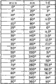
Fig. 5 is a table, is illustrated in the prototype engine similar to the mode of execution of Fig. 1, and piston moves and the relation of output shaft between rotating;
Fig. 6 A-6I is illustrated in the mode of execution of Fig. 1-3, the figure of the stroke that piston carries out during a revolution of output shaft;
Fig. 7 is a table, is illustrated in during the output shaft rotation of 360 degree, and in the mode of execution of Fig. 1-3, the stroke that in all chambeies, takes place;
Fig. 8 is an isometric view that cuts away according to the part of another mode of execution of positive-displacement engine of the present invention;
Fig. 9 is in different working positions, the incomplete isometric view of the crankcase components of the mode of execution of Fig. 8;
Figure 10 is the isometric view of the shell in the mode of execution of Fig. 8, and one of end cap is shown in an open position;
Figure 11 is an incomplete isometric view roughly similar to FIG. 10, and end cap is in the original position;
Figure 12 is the isometric view of one of rotor in the mode of execution of Fig. 8, and piston is in the annular cylinder;
Figure 13 is the isometric view of the output shaft in the mode of execution of Fig. 8;
Figure 14 is the incomplete cross-sectional view of the rotor in the mode of execution of Fig. 8;
Figure 15 is the cross-sectional view of the crankweb in the mode of execution of Fig. 8;
Figure 16 A-16I is the figure similar to Fig. 6 A-6I, and expression is configured as the work of the motor of a pump;
Figure 17 is a table, and expression occurs in the stroke in all chambeies when motor during as a pump work.
As shown in Fig. 1-3, motor has a pair of rotor 21,22 that has piston 23,24, and piston 23,24 separates on the circumferencial direction of rotor and is arranged in an annular chamber or the cylinder 26.Each piston of a rotor is put between each piston of another rotor in the described a pair of rotor, and chamber 27 is formed on two rotors between in succession the piston.As more expounding adequately hereinafter, two rotors are with the step-by-step system alternate rotation, when an epitrochanterian piston keeps static basically, and another epitrochanterian piston-advance.When piston-advance, chamber 27 changes on volume, and the chamber volume on the rear side of mobile piston increases, and the chamber volume on the front side reduces.By the alternating motion of rotor, the chamber that increases at volume during the stepping will reduce by volume during next stepping.
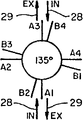
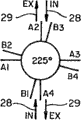
Fuel is introduced in the chamber by suction port 28, and waste gas is discharged by relief opening 29, and these mouthfuls are in couples around cylinder arrangement, and in illustrated embodiment, two counterparts are directly placed relative to one another.These mouthfuls are open also directly to be communicated with cylinder.
Carriage or support 37 join output shaft to by spline, and a pair of bent axle 38,39 is installed on the carriage rotatably, equate from the axial line distance of output shaft.Planetary pinion 41 is arranged on the end of bent axle, and they and 42 engagements of sun gear, and sun gear 42 is co-axially mounted in the fixed position with output shaft.Sun gear is preferably identical with each epitrochanterian number of pistons with planetary velocity ratio, i.e. n: 1, and wherein n is each epitrochanterian number of pistons.In the mode of execution of Fig. 1, four pistons are arranged on each rotor, gear ratio is 4: 1.Under the situation of this velocity ratio, the stepping that piston carries out approximately is each 90 degree, and for each revolution of output shaft, each piston carries out four this steppings.
Certainly, can use the piston of varying number and different gear ratios, but the number of pistons of each rotor preferably should be identical with gear ratio, promptly each rotor n piston and gear ratio are n: 1.Under the situation of the velocity ratio of more piston and Geng Gao, piston steps reduces dimensionally and quantitatively increases, and under the situation of less piston and lower gear ratio, stepping increases dimensionally and quantitatively reduces.Thereby for example, under the situation of the gear ratio of eight pistons of each rotor and 8: 1, for each revolution of output shaft, each piston will carry out eight steppings, each 22.5 degree.Under the situation of the velocity ratio of two pistons of each rotor and 2: 1, piston will only carry out twice stepping, each 180 degree.In other words, n: 1 gear ratio provides n stepping in each revolution, and each stepping is 360 °/n.
Crankweb and bent axle have crank pin 43,44, and they link together by connecting rod 46,47, and the throw of eccentric of bent axle (throw) is less than the throw of eccentric of crankweb, and this makes bent axle to rotate continuously, even piston and rotor can not be done like this.
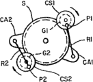
The stepping of in Fig. 4 A-4E, further having illustrated rotor and piston move and the continuous rotation of output shaft between relation, in these figure, the symbol below having used:
Sun gear S
Bent axle CS1, CS2
Crank pin P1, P2
Planetary pinion G1, G2
Crankweb CA1, CA2
Connecting rod R1, R2
Suppose that gear ratio is 4: 1, bent axle CS1 begins in top dead center (TDC) position, and bent axle CS2 begins in lower dead center (BDC).In those positions, the crank pin on bent axle and the crankweb aligns on the straight line by crankshaft center line.In tdc position, crank pin is between crankweb and crankshaft center line, and crankweb is in its most advanced, promptly from crankshaft center line position farthest.In the BDC position, crank pin is positioned at outside the crankshaft center line, and crankweb is in it near in the minimum advancement position of crankshaft center line.
Bent axle and planetary pinion are installed on the carriage, and this carriage joins output shaft to, and bent axle and planetary pinion as one man rotate around the axis and the output shaft of output shaft.Because planetary pinion moves around sun gear, so they make the axle continuously rotation of bent axle around them, moving 90 degree of output shaft revolution, bent axle and planetary pinion just carry out a revolution.
After output shaft rotates 22.5 degree, bent axle and planetary pinion will rotate to the position shown in Fig. 4 B.At this point, except moving 22.5 degree around sun gear, bent axle and planetary pinion have also rotated 90 degree around their axle itself, the summation of crank pin P1, the clean stroke of the P2 stroke that to be them caused by these two rotations.
Because be on the identical direction around the mobile of sun gear with planetary pinion G1 around the moving of the caused crank pin of axle rotation of itself by planetary pinion G1, crankweb CA1 moved towards its progressive position so these two mobile components add together.
Yet, during this part of circuit, rotate the mobile opposite around the direction that sun gear moves of caused crank pin P2, result around the axle of itself with planetary pinion by planetary pinion G2, these two mobile components cancel each other out, and it is static that crankweb CA2 keeps in its home position basically.
During the axle rotation of next 22.5 degree, bent axle and planetary pinion move another 22.5 degree and rotate another 90 degree around their axles own around sun gear, arrive the position shown in Fig. 4 C, make bent axle CS1, CS2 arrive their TDC and BDC position respectively.During this part of circuit, the crank pin P1 that causes by bent axle and planetary rotation mobile keep with around the mobile phase of sun gear with direction on, and crankweb CA1 advances to its most advanced.Crank pin CP2 moves still mobile opposite with around sun gear around the rotation of crankshaft center line, and these two components continue to cancel each other out, and it is static that crankweb CA2 keeps basically.
In case bent axle CS1 arrives TDC, crank pin P2 around the rotation of crankshaft center line move just be in around the mobile phase of sun gear with direction on, so two components add together, crankweb CA2 begins to advance.Yet now, crank pin CA1 moves opposite with mobile direction around sun gear around the rotation of its crankshaft center line, and these two mobile components cancel each other out, and it is static that crankweb CA1 keeps basically.After the axle rotation of 22.5 degree, gear will arrive the position shown in Fig. 4 D.
During the axle rotation of next 22.5 degree, bent axle and planetary pinion will move another 22.5 degree, the position shown in arrival Fig. 4 E around their another 90 degree of axle rotation own and around sun gear.In this part of circuit, the rotation of crank pin CP2 move still be in its around the mobile phase of sun gear with direction on, and two components continue stack and crankweb CA2 are advanced.The rotation of crank pin P1 is moved and is continued and its mobile opposite around sun gear, and these two components continue to cancel each other out, and it is static that crankweb CA1 keeps basically.
At this point, bent axle and planetary pinion have rotated 360 complete degree around their axle itself, and they have moved 90 degree around sun gear, and output shaft has rotated 90 degree around its axle.Crankweb 90 degree that also advanced, but be mode with stepping are the same with rotor on being connected to piston as piston.For each revolution of output shaft, this circulation repeats four times.
Because output shaft and rotor link together by connecting rod, so they rotate together with identical Sum velocity, for each revolution of output shaft, rotor all carries out a revolution completely.Yet because the effect of bent axle and crankweb, when rotor rotated with output shaft, rotor in fact also swung back and forth, and produced the stepping rotation.
Because the motion parts ground of crankweb is by the constraint of the circular movement of the crank pin on the bent axle, so the motion of crankweb and rotor is not linear.When bent axle was near TDC and BDC, it was the slowest, and circular movement is approximately perpendicular to pitman shaft, and when near the neutral position of bent axle between TDC and BDC, it is the fastest, and circular movement and pitman shaft are more in line approaching.This is non-linear in the whole endurance, cause about 9 degree keep stroke (carry), this makes two epitrochanterian pistons to stop in the substantially the same position of different time between suction port and relief opening.
Be to have represented that piston moves and the relation of output shaft between rotating more with the experiment in Fig. 5 according to ground.Data in this table are to obtain by having the measurement of carrying out on 4: 1 the model machine motor (prototypeengine) of gear ratio, in this example, circulation begins from the bent axle that is in BDC (0 °), and an epitrochanterian piston is connected to that bent axle in zero degree (0 °) reference point.
This data representation turns to 40 when spending from 10 degree when output shaft, and clean piston stroke only is 2.5 degree and moves to the time durations of 35 degree at piston from 15 degree, and it is zero that clean piston moves, and when axle moves to 30 when spending from 25 degree, in fact piston has had on a small quantity and fall back.When axle arrived the point of 40 degree, piston began to move quickly, and when axle advances to 90 when spending from 40 degree, piston advances to 90 degree from 12.5 degree.For the axle position between 50 degree and 85 degree, moving 5 degree of axle revolution, piston moves about 8 to 10 degree, and when axle arrives 85 when spending, piston slows to approximately and an identical speed once more.In whole circulation, output shaft and bent axle rotate continuously and equably, and be indicated as the interval of the rule in their motions.
When bent axle moved around their axle rotations own with around sun gear, the counteracting of bent axle was moved effectively rotor and piston is locked in their the static basically position.When the piston on a rotor and its during by locking, another rotor and the piston on it freely advance, thereby, when burning takes place, kept static basically by the rotor of locking, and drive forwards in another epitrochanterian piston all one's effort with expanding gas, the motion of that rotor drives the bent axle that is connected thereto, the rotation of bent axle impels the planetary pinion on that bent axle to move around sun gear, when it so carries out, just makes the output shaft rotation that joins carriage to.At the next power stroke that almost begins immediately, another rotor is driven, and is connected to the crank-driven output shaft of that rotor, and output shaft rotates continuously, and 16 power strokes are held in per 360 degree rotations.
Under the situation of the rotation that does not interrupt or put upside down bent axle, gear and output shaft, the step motion and the locking of rotor are implemented.This is to be better than one of conventional engines main the improvement, and in conventional engines, output shaft whenever revolves and turns around, and piston must stop and inverted orientation twice, and each power stroke, piston must stop and inverted orientation four times.
It is very close in the beginning and the end of each stroke that rotor can be set the apparent surface who makes piston for, and start function to have very high compression ratio, for example 35: 1 or higher.Thereby, start function with the diesel engine mode operation, there are not spark plug or ignition circuit and ignition timing.Yet if wish, it also can lean on gasoline or another kind to need spark so that the burnt fuel operation in this case, can be adopted suitable ignition system.
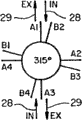
Motor operates in 4 stroke cycle, and it diagrammatizes in Fig. 6 A-6I.In these figure, rotor indicates that with A and B epitrochanterian piston is indicated with A1, B1 or the like.Begin at circuit, rotor is in the position shown in Fig. 6 A, and piston B1 and B3 form the sealing between suction port 28 and the relief opening 29.In these figure, suction port and relief opening are respectively by the arrow representative that is labeled as IN and EX.
During the axle rotation of first 45 degree, about 90 degree of the piston-advance on the rotor A arrive the position shown in Fig. 6 B, and it is static that the piston on the rotor B keeps basically.When the piston-advance on the rotor A, be formed at the aspirating stroke of chamber experience between piston A1, B1 and A3, the B3, volume increases, and by suction port 28 with fuel mixture suck they self in.
During the axle rotation of next 45 degree, about 90 degree of the piston-advance on the rotor B arrive the position shown in Fig. 6 C, and it is static that the piston on the rotor A keeps basically.When the piston-advance on the rotor B, compression stroke of chamber between piston A1, B1 and A3, B3 experience, volume reduces, and in them compressed fuel mixture.
The compression of fuel mixture makes its temperature be elevated to burning-point, and the burning that causes impels the chamber volume between piston A1, B1 and A3, the B3 to increase, and rotor B keeps static and rotor A another 90 degree that advances basically, arrives the position shown in Fig. 6 D.During this power stroke, output shaft rotates another 45 degree.
During the next 45 axle rotations of spending, about 90 degree of the piston-advance on the rotor B arrive the position shown in Fig. 6 E, and it is static that the piston on the rotor A keeps basically, and the sealing between A1 and A3 formation suction port and the relief opening.When the piston-advance on the rotor B, the chamber volume between piston A1, B1 and A3, B3 reduces, and discharges gas of combustion by relief opening 29.
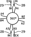
After exhaust stroke, this repetition that circulates, the chamber between piston A1, B1 and A3, B3 experiences another aspirating stroke, and the piston-advance on the rotor A is to the position shown in Fig. 6 F.During the axle rotation of next 45 degree, the piston-advance on the rotor B is to the position shown in Fig. 6 G, compressed fuel mixture in these chambeies.The burning of compressed fuel mixture is the position of the piston actuated on the rotor A shown in Fig. 6 H, output shaft another 45 degree that advances.During the axle rotation of next 45 degree, the piston-advance on the rotor B is to the position shown in Fig. 6 I, and combustion gas is also finished circulation.Now, piston and axle have been finished the rotation of 360 degree, and piston is got back in the position shown in Fig. 6 A, prepare next circulation.
Simultaneously, the chamber that is formed between piston A1, B1 and A3, the B3 is experiencing their work cycle, and similar circulation is also just occurring in the chamber that is formed between other piston.Thereby, for example, when rotor A moving between the position shown in Fig. 6 A and the 6B and chamber between piston A1, B1 and A3, B3 in when aspirating stroke taking place, compression stroke is taking place in the chamber between piston A1, B2 and A3, B4, in the chamber between piston A2, B2 and A4, B4 power stroke taking place, in the chamber between piston A2, B3 and A4, B1 exhaust stroke is taking place.
Fig. 7 is illustrated in the stroke that betides in the 360 axle rotations of spending in the chamber.From this chart, can see during each revolution of output shaft, motor all experiences two complete work cycle in each of eight chambeies, thereby, two power strokes are arranged in each chamber, in two revolutions of output shaft, 32 power strokes are altogether arranged in eight chambeies, this equals 32 Cylinder engines of traditional design.
Employing is rotated in annular cylinder and the active chamber of shared same space, and motor obtains quite high discharge capacity (displacement) in relatively little space.For example, in one embodiment, annular cylinder has 11.25 inches external diameter, and each chamber has 3.0 inches diameter and 3.75 inches stroke, has total effective discharge of 424 cubic inches in a revolution of output shaft.Use two revolutions as the axle in traditional 4 two-stroke engines, motor just has almost 850 cubic inches effective discharge.When being constructed by the material of high strength, light weight, each has about 14 inches overall diameter and length and about 200 pounds weight motor.This is the very big and important improvement that is better than the tradition 6 cylinder in line engine of reciprocity discharge capacity, and 6 traditional cylinder in line engine have about 5 feet length usually, about 2 feet width, about 4 feet height and about 2500 pounds weight.
In addition, power output is in fact greater than the power output of the conventional engines of reciprocity discharge capacity.The motor of above-mentioned 850 cubic inch displacements (C.I.D.) is considered to export 2000 horsepowers or bigger, and the common output of traditional 850C.I.D. is no more than about 400 horsepowers.
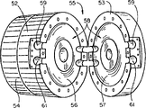
Fig. 8-15 represents current preferred implementation, and wherein motor is constructed in a cylindrical shell 51, and cylindrical shell comprises middle body 52 and end cap 53,54, and radiating fin is located on the outside of all three parts.One end of shell is as engine cylinder body 55, and the other end holds a crankcase.In cylinder block, the circular groove 56,57 of semi-circular cross-section is formed at middle body 52 and covers among 53 the apparent surface, to form the annular chamber or the cylinder 58 of piston.Radial hole 59,61 openings pass the apparent surface and in conjunction with forming air inlet and relief opening, ring bridge (not shown) is crossed over porting, to prevent damaging piston ring when piston ring moved porting.
A pair of rotor 68,69 and output shaft coaxial arrangement with the foliaceous piston 71,72 that separates on circumference, each piston of a rotor is put between each piston of another rotor in the described a pair of rotor, thereby cylinder 58 is divided into a plurality of chambeies.In this embodiment, rotor and piston form single structure, and piston has circular cross section, and have sagittal plane 73,74 on it has intercepted the opposite side of about 9 degree angles.Rotor has disc-shaped main body 68a, 69a, and disc-shaped main body has recessed crooked peripheral surface 68b, 69b, and the curvature of peripheral surface and groove 56,57 is complementary and is used as the part of cylinder wall.
Sealing between two rotors is provided by ring 76, and ring 76 is among circular groove 68c, the 69c in the internal surface of rotor disk.Sealing between rotor and the cylinder block 77 is provided by ring, and ring 77 is among circular groove 68d, the 69d in the rotor outer surface and surface housing parts 52 and end cap 53.Piston has peripheral annular groove and ring 70, and ring 70 forms sealing near cylinder wall.
If in preferred implementation, then the cross section of piston and cylinder is circular, can use traditional piston ring.Yet piston and cylinder are not must be circular, and they can have desirable any other cross-sectional profiles, comprise rectangle and trapezoidal.
Rotor is connected to crankweb 78,79 in the crankcase by hollow shaft or sleeve 81,82, hollow shaft 31,32 in the mode of execution of hollow shaft 81,82 and Fig. 1-3 is similar, these axles and output shaft 63 coaxial arrangement, interior hollow shaft 81 is installed on the output shaft rotatably, and hollow outer shaft 82 is installed on the interior hollow shaft rotatably.Interior hollow shaft is longer than hollow outer shaft slightly, and rotor 68 and crankweb 78 join end, rotor 69 and the crankweb 79 same protruding terminuss that join interior axle by spline 84 to of outer shaft to by spline 83.
Each crankweb has two roughly radially arm 78a, 78b and 79a, 79b, only in them joins hollow shaft to, another arm is installed on the output shaft rotatably to gain in strength and stability, and crank pin 78c, 79c extend between two arms of each crank.
Support or carriage 86 join output shaft 63 to by spline 87, and a pair of bent axle 88,89 is installed on the carriage on the relative position of diameter rotatably.Bent axle has planetary pinion 88a, 89a, they form bent axle integral part and with sun gear 91,92 engagement, sun gear join to shell and with axle 63 coaxial arrangement.Bent axle also has eccentric (eccentric), and it is connected to crank pin 78c, 79c on the crankweb by connecting rod 93,94.
The operation of this mode of execution and use be to aforesaid similar, and under the situation of the gear ratio of four pistons of each rotor and 4: 1, this motor is also in each revolution igniting 16 times of output shaft and igniting 32 times in two revolutions.As above mentioned, it can from size only be 14 inch diameters and 14 inchages and weight only for output about 200 pounds complete sets of equipment 2000 or more horsepower.
If wish that by one second annular cylinder being increased to the outboard end of crankcase and rotor in this cylinder and piston being attached to existing driving mechanism, a second level can be increased on the motor of Fig. 8-15.It can be realized in the following way, output shaft 63 extended through the cylinder of increase and other a pair of hollow shaft is installed in the extension of live axle, one end spline of hollow shaft is connected to free arm 78b, the 79b of crankweb, and the other end spline is connected to the rotor of increase.When this finished, single driving mechanism was two piston services in the cylinder, and the power of motor can double, and the size of motor is doubled yet.
Motor turns round very effectively and can use various replacement fuel and diesel oil and gasoline, and it also can be used as incinerator, be used for burning liquefied and with the rubbish of another fuel-bound, be rubbish wherein up to about percent 70 mixture.The application that it also can be configured to tiny engine and be used for for example charging to the battery supply group.
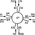
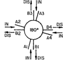
By with described salty new arrangement with drive output shaft, motor can also be configured to be used as the device of pump.For a pump, the quantity that is preferably such that mouthful equals the quantity of epitrochanterian piston, thereby for example, under the situation of four pistons of each rotor, the four pairs of air inlets and relief opening on average separate around cylinder.As shown in figure * (IN) and the * (DIS), piston advances at every turn, and it is all with in the chamber of fluid suction after it, and from the chamber before it, discharge fluid, this produces a pump, and this pump can have high volume, high flow capacity and high pressure, all in the unit of a compactness.
If wish that pump can be used the engine type classification of Fig. 8-15, a single driving mechanism is used for two-stage.
The present invention has a large amount of important feature and advantage, and it provides very compact and motor efficiently, and it can be used for big and little various application, its can burn various fuel and moving in the diesel engine pattern or move with spark ignition.In automobile was used, high combustion efficiency and big discharge capacity provided very high fuel mileage and high power, engine components seldom, its simplicity of design and grace, it can also be configured as a pump under the situation that does not change basic system.
From aforementioned content, clearly, a kind of new and method improved internal-combustion engine and this internal-combustion engine of operation are provided.Although only describe some preferred implementation in detail, for those those of ordinary skills, clearly, can carry out some change and modification in the case without departing from the scope of the present invention, scope of the present invention is limited by following claim.
Claims (35)
1. internal-combustion engine, comprise an annular cylinder, the a pair of axis rotor rotated that is fit to around annular cylinder, each epitrochanterian four piston is divided into eight chambeies with cylinder, output shaft with described cylinder coaxial arrangement, join the carriage of described output shaft to, the a pair of bent axle that is installed in rotatably on the described carriage, one timing mechanism, output shaft and bent axle are connected to each other for it so that for each revolution of output shaft, bent axle carries out four revolutions, crankweb, the throw of eccentric of described crankweb is greater than the throw of eccentric of bent axle, crankweb links to each other with rotor and some connecting rods for the motion that cooperates rotor, and it is connected to each other crankweb and bent axle, so that bent axle rotates continuously and rotor alternately rotates with step-by-step system, carries out a revolution completely for each revolution of output shaft.
2. internal-combustion engine as claimed in claim 1, wherein said timing mechanism comprises the static sun gear with described output shaft coaxial arrangement, and be connected to bent axle with the sun gear planet gear meshed, described sun gear and planetary pinion have 4: 1 velocity ratio, to a revolution of output shaft, each all carries out four revolutions described bent axle thus.
3. internal-combustion engine, comprise: an annular cylinder, output shaft with described cylinder coaxial arrangement, sun gear with described axle coaxial arrangement, join the carriage of described axle to, the a pair of bent axle that is installed in rotatably on the described carriage, gear on the described bent axle and sun gear engagement, the a pair of axle rotor rotated that is suitable for around described cylinder, each rotor comprises a plurality of pistons, make each piston of one of them rotor be put between each piston of another rotor, thereby described piston is divided into a plurality of chambeies with cylinder, a pair of crank, the crank pin that each crank all has a pair of radial arm and extends between described radial arm, crank pin is supported symmetrically by described radial arm, the throw of eccentric of described crank is greater than the throw of eccentric of bent axle, described crank links to each other with rotor for the motion that cooperates rotor, make corresponding rotor and crank be connected to each other the device that rotates with consistent, with make the interconnected connecting rod of bent axle and crank, described thus bent axle rotates continuously, rotor carries out a complete revolution with alternately rotation of step-by-step system for each revolution of output shaft.
4. internal-combustion engine as claimed in claim 3 wherein has n piston and described sun gear and crankshaft gear to have n on each rotor: 1 velocity ratio.
5. internal-combustion engine as claimed in claim 3, wherein said bent axle and the interconnected device of crank of making comprises a pair of hollow shaft, it is arranged with one heart and joins on corresponding rotor and the crank about described output shaft.
6. internal-combustion engine as claimed in claim 5, wherein one of radial arm on each crank joins in the hollow shaft on the corresponding hollow shaft, and another radial arm is installed in rotatably on the output shaft and by output shaft and supports.
7. internal-combustion engine, comprise: an annular cylinder, the a pair of axis rotor rotated that is fit to around annular cylinder, each rotor comprises four pistons, make each piston of one of them rotor be put between each piston of another rotor, thereby described piston is divided into eight chambeies with cylinder, output shaft with described cylinder coaxial arrangement, sun gear with the output shaft coaxial arrangement, join the carriage of described output shaft to, the a pair of bent axle that is installed in rotatably on the described carriage, gear on the bent axle and sun gear engagement and sun gear and crankshaft gear have 4: 1 velocity ratio, crankweb, the throw of eccentric of described crankweb are greater than the throw of eccentric of bent axle, and crankweb links to each other with rotor for the motion that cooperates rotor, with some connecting rods, it is connected to each other crankweb and bent axle, so that bent axle rotates continuously and rotor alternately rotates with step-by-step system, carries out a revolution completely for each revolution of output shaft.
8. the method for an operation of combustion engine, described internal-combustion engine has an annular cylinder, output shaft with described cylinder coaxial arrangement, the a pair of axle rotor rotated that is suitable for around described cylinder, epitrochanterian four pistons are divided into cylinder in the chamber of eight variable volumes, comprise the following steps: piston to be advanced around cylinder with step-by-step system by the burning of the fuel mixture in the described chamber, described rotor as one man rotates with step-by-step system and piston, the stepping of rotor rotation is transformed into a pair of continuous rotation that is installed in the bent axle on the carriage through crankweb and connecting rod, described carriage joins on the output shaft, with will pass to described carriage and output shaft from the continuous rotation of bent axle, each rotation for output shaft, bent axle carries out four rotations, the throw of eccentric of wherein said crankweb is greater than the throw of eccentric of bent axle, crankweb links to each other with rotor for the motion that cooperates rotor, described connecting rod connecting crank arm and bent axle.
9. method as claimed in claim 8, wherein the crank by being connected to rotor and be connected crank and bent axle between connecting rod, the stepping rotation of described rotor is transformed into the continuous rotation of bent axle, described crank has longer throw of eccentric than bent axle.
10. method as claimed in claim 8, wherein by making planetary pinion and the sun gear engagement that is connected to bent axle, described continuous rotation is passed to carriage and output shaft, and described sun gear and output shaft are arranged coaxially.
11. an internal-combustion engine comprises:
A. an annular cylinder;
B. with the output shaft of described cylinder coaxial arrangement;
C. be installed in first hollow shaft on the described output shaft rotatably;
D. be installed in second hollow shaft on described first hollow shaft rotatably;
E. pair of engaging rotor on the corresponding hollow shaft in the described hollow shaft;
F. each epitrochanterian four piston makes each piston of one of them rotor be put between each piston of another rotor, thereby cylinder is divided into eight chambeies;
G. with the sun gear of described output shaft coaxial arrangement;
H. join the carriage of described output shaft to;
I. a pair of bent axle that is installed in rotatably on the described carriage, gear on the bent axle and the engagement of described sun gear, be used for when when rotation axle of described bent axle around them, make the axis rotation of described carriage and output shaft around output shaft, gear on described sun gear and the bent axle has 4: 1 velocity ratio, for a revolution of output shaft, each in the described bent axle all carried out four revolutions thus;
J. pair of engaging crankweb on the corresponding hollow shaft in the described hollow shaft, the throw of eccentric of described crankweb is greater than the throw of eccentric of bent axle; With
K. make the interconnected connecting rod of described crankweb and bent axle, so that crankweb is with the step-by-step system alternate rotation, an epitrochanterian piston moved an intended distance around cylinder when, another epitrochanterian piston kept static and described bent axle and output shaft to rotate continuously basically.
12. an internal-combustion engine comprises:
A. cylindrical shell has cylinder block and crankcase towards its opposite end;
B. be formed at the annular cylinder in the described cylinder block;
C. at the upwardly extending output shaft of axle of described shell and the bent axle that is connected with output shaft;
D. be installed in first hollow shaft on the described output shaft rotatably;
E. be installed in second hollow shaft on described first hollow shaft rotatably;
F. a pair of rotor, it joins on the corresponding hollow shaft of the hollow shaft in the described cylinder block;
G. at each epitrochanterian a plurality of piston, make each piston of one of them rotor be put between each piston of another rotor, thereby annular cylinder is divided into a plurality of chambeies;
H. a pair of crank, its each all have first radial arm that joins on one of described hollow shaft, second radial arm that is installed in rotatably on the output shaft and supports by output shaft, and the crank pin that between described radial arm, extends, the throw of eccentric of crank is greater than the throw of eccentric of bent axle; With
I. the device that comprises connecting rod, connecting rod are connected to each other described crank and bent axle, and this device is used for the stepping rotation of piston and rotor and the continuous rotation of output shaft.
13. an internal-combustion engine comprises:
A. an annular cylinder;
B. around paired suction port and the relief opening of settling of described cylinder;
C. with the output shaft of described cylinder coaxial arrangement;
D. be installed in first hollow shaft on the described output shaft rotatably;
E. be installed in second hollow shaft on described first hollow shaft rotatably;
F. pair of engaging rotor on the corresponding hollow shaft in the described hollow shaft;
G. each epitrochanterian four piston makes each piston of one of them rotor be put between each piston of another rotor, thereby cylinder is divided into a plurality of chambeies;
H. pair of engaging crankweb on the corresponding hollow shaft in the described hollow shaft is used for as one man rotating with described rotor and piston;
I. with the sun gear of described output shaft coaxial arrangement;
J. join the carriage of described output shaft to;
K. a pair of bent axle that is installed in rotatably on the described carriage, the throw of eccentric of described crankweb is greater than the throw of eccentric of bent axle;
L. make the interconnected connecting rod of described crankweb and bent axle, so that when described crankweb during with the step-by-step system alternate rotation, described bent axle rotates continuously, when an epitrochanterian piston keeps static basically and form sealing between described suction port and relief opening, another epitrochanterian piston-advance, with in the chamber that fuel sucks with suction port is communicated with and with waste gas from chamber that relief opening is communicated with discharge; With
M. the gear on described bent axle, itself and described sun gear mesh, be used for moving and when rotation axle of described bent axle with step-by-step system around them when described piston, described carriage and output shaft are rotated continuously around the axis of output shaft, gear on described sun gear and the bent axle has 4: 1 velocity ratio, for a revolution of output shaft, each in the described bent axle all carried out four revolutions thus.
14. machine that is used for conversion between rotation and stepping are rotated continuously, comprise: an axle, sun gear with described axle coaxial arrangement, join the carriage of described axle to, one has the bent axle of eccentric crank pin, crank pin is installed in rotatably and has on the planetary carriage, planetary pinion and sun gear engagement, so that when described planetary pinion moves around sun gear, described axle and bent axle are around their axle rotation continuously, one crank of installing rotatably, it has a pair of radial arm and extend and be supported on the crank pin at radial arm two ends between described radial arm, the throw of eccentric of described crank is greater than the throw of eccentric of bent axle, crank links to each other with rotor for the motion that cooperates rotor, with a connecting rod, this connecting rod is connected to each other crank pin and the crank on the described bent axle, so that when bent axle rotates continuously, described crank rotates with step-by-step system, when the motion by the caused crank pin of rotation of bent axle is added to by planetary pinion around the motion of the mobile caused described pin of sun gear, advance and when having offset the motion of moving caused described pin, keep static basically by planetary pinion by the motion of the caused crank pin of crankshaft rotating.
15. machine that is used for conversion between rotation and stepping are rotated continuously, comprise: an axle, sun gear with described axle coaxial arrangement, join the carriage of described axle to, first and second bent axles with eccentric crank pin, crank pin is installed in rotatably and has on the planetary carriage, planetary pinion and sun gear engagement, so that when described planetary pinion moves around sun gear, described bent axle is around their axle rotation continuously, first and second cranks of installing rotatably, each crank has a pair of radial arm and extend and be supported on the crank pin at radial arm two ends between described radial arm, the throw of eccentric of described crank is greater than the throw of eccentric of bent axle, crank links to each other with rotor for the motion that cooperates rotor, and first and second connecting rod, described connecting rod is connected to each other crank pin and the crank on the described bent axle, so that when bent axle rotates continuously, described crank rotates with step-by-step system, when the motion by the caused crank pin of rotation of bent axle is added to by planetary pinion around the motion of the mobile caused described pin of sun gear, advance and when having offset the motion of moving caused described pin, keep static basically by planetary pinion by the motion of the caused crank pin of crankshaft rotating.
16. machine as claimed in claim 15, the crank pin phase place on wherein said two bent axles be separated by 180 the degree so that one of described crank keep basically static in, another advances.
17. the method for an operation of combustion engine, described internal-combustion engine has an annular cylinder, be arranged in the two pairs of air inlets and relief opening on the described cylinder opposite side, output shaft with the cylinder coaxial arrangement, the a pair of axle rotor rotated that is suitable for around described cylinder, each rotor has four pistons, each piston of one of them rotor is put between each piston of another rotor, thereby cylinder is divided into eight chambeies, its step comprises: the burning by the fuel mixture in the described chamber makes piston advance with step-by-step system around cylinder, it is static that piston on one of rotor keeps between described suction port and relief opening basically, another epitrochanterian piston-advance with fuel is sucked with chamber that suction port is communicated with in and with waste gas from chamber that relief opening is communicated with discharge, the stepping rotation of described rotor is transformed into a pair of continuous rotation that is installed in the bent axle on the carriage through crankweb and connecting rod, carriage joins described output shaft to and will pass to described carriage and output shaft from the continuous rotation of bent axle; To a revolution of output shaft, each all carries out four revolutions described bent axle, and the throw of eccentric of described crankweb is greater than the throw of eccentric of bent axle, and crankweb links to each other with rotor for the motion that cooperates rotor, and connecting rod links to each other described crankweb with described bent axle.
18. method as claimed in claim 17, wherein the crank by being connected to rotor and be connected crank and bent axle between connecting rod, the stepping rotation of described rotor is transformed into the continuous rotation of bent axle, described crank has longer throw of eccentric than bent axle.
19. method as claimed in claim 17, wherein by making a planetary pinion and a gear engagement that is connected to bent axle, described continuous rotation is passed to carriage and output shaft, and this gear and output shaft are arranged coaxially.
20. an internal-combustion engine comprises:
A. cylindrical shell has cylinder block and crankcase towards its opposite end;
B. be formed at the annular cylinder in the described cylinder block;
C. described shell the axle upwardly extending output shaft;
D. be installed in first hollow shaft on the described output shaft rotatably;
E. be installed in second hollow shaft on described first hollow shaft rotatably;
F. a pair of rotor, it joins on the corresponding hollow shaft of the hollow shaft in the described cylinder block;
G. at each epitrochanterian four piston, make each piston of one of them rotor be put between each piston of another rotor, thereby annular cylinder is divided into eight chambeies;
H. make the interconnected device of output shaft in described hollow shaft and the crankcase, it is used for the stepping rotation of piston and rotor and the continuous rotation of output shaft, described device comprises the crankweb that links to each other with hollow shaft, the bent axle that is connected with output shaft, and the connecting rod of connecting crank arm and bent axle, the throw of eccentric of described crankweb is greater than the throw of eccentric of bent axle.
21. internal-combustion engine as claimed in claim 20, wherein said hollow shaft and the interconnected device of output shaft of making comprises:
(1) a pair of crank arm, it joins in the described hollow shaft on the corresponding hollow shaft, is used for as one man rotating with described rotor;
(2) join the carriage of described output shaft to;
(3) a pair of bent axle that is installed in rotatably on the described carriage;
(4) with the sun gear of described output shaft coaxial arrangement;
(5) on bent axle and described sun gear meshed gears, be used for when when rotation axle of described bent axle around them, make the axis rotation of described carriage and output shaft around output shaft, gear on described sun gear and the bent axle has 4: 1 velocity ratio, and for a revolution of output shaft, described bent axle carries out four revolutions; With
(6) make the interconnected connecting rod of described crankweb and bent axle.
22. internal-combustion engine as claimed in claim 20 comprises two pairs of suction port and relief openings on the opposite side that is placed in described annular cylinder.
23. internal-combustion engine as claimed in claim 20 wherein has n piston on each rotor, n/2 separates and described sun gear and crankshaft gear have n: 1 velocity ratio around cylinder fifty-fifty to suction port and relief opening.
24. an internal-combustion engine comprises:
A. an annular cylinder;
B. two pairs of suction port and relief openings that are arranged on the described cylinder opposite side;
C. with the output shaft of described cylinder coaxial arrangement;
D. with the sun gear of described output shaft coaxial arrangement;
E. join the carriage of described output shaft to;
F. a pair of bent axle that is installed in rotatably on the described carriage;
G. a pair of axis rotor rotated that is suitable for around described cylinder;
H. at each epitrochanterian four piston, make each piston of one of them rotor be put between each piston of another rotor, thereby cylinder is divided into a plurality of chambeies;
I. crankweb, the throw of eccentric of described crankweb is greater than the throw of eccentric of bent axle, and crankweb links to each other with rotor for the motion that cooperates rotor; And make described crankweb and the interconnected connecting rod of bent axle, so that when rotor during with the step-by-step system alternate rotation, described bent axle rotates continuously, when an epitrochanterian piston keeps static basically and form sealing between described suction port and relief opening, another epitrochanterian piston-advance, with in the chamber that fuel sucks with suction port is communicated with and with waste gas from chamber that relief opening is communicated with discharge; With
J. the gear on described bent axle, itself and described sun gear mesh, be used for moving and when rotation axle of described bent axle with step-by-step system around them when described piston, described carriage and output shaft are rotated continuously around the axis of output shaft, described sun gear and crankshaft gear have 4: 1 velocity ratio, and for each revolution of output shaft, described bent axle carries out four revolutions.
25. internal-combustion engine as claimed in claim 24, wherein for the output shaft rotation of about 9 degree, described piston keeps static basically and form sealing between suction port and relief opening.
26. an internal-combustion engine comprises:
A. an annular cylinder;
B. with the output shaft of described cylinder coaxial arrangement;
C. be installed in first hollow shaft on the described output shaft rotatably;
D. be installed in second hollow shaft on described first hollow shaft rotatably;
E. pair of engaging rotor on the corresponding hollow shaft in the described hollow shaft;
F. at described epitrochanterian a plurality of pistons, make each piston of one of them rotor be put between each piston of another rotor, thereby cylinder is divided into a plurality of chambeies;
G. with the sun gear of described output shaft coaxial arrangement;
H. join the carriage of described output shaft to;
I. a pair of bent axle that is installed in rotatably on the described carriage, the engagement of the gear on the bent axle and described sun gear is used for when described bent axle during around their axle rotation described carriage and output shaft being rotated around the axis of output shaft;
J. a pair of crank, each crank all has first radial arm that joins in the described hollow shaft on the corresponding hollow shaft, second radial arm that is installed in rotatably on the output shaft and supports by output shaft, and the crank pin that between described radial arm, extends and support symmetrically by radial arm, the throw of eccentric of described crank is greater than the throw of eccentric of bent axle; With
K. make the interconnected connecting rod of described crank and bent axle, so that crankweb is with the step-by-step system alternate rotation, an epitrochanterian piston moved an intended distance around cylinder when, another epitrochanterian piston kept static and described bent axle and output shaft to rotate continuously basically.
27. an internal-combustion engine comprises:
A. an annular cylinder;
B. around paired suction port and the relief opening of settling of described cylinder;
C. with the output shaft of described cylinder coaxial arrangement;
D. with the sun gear of described output shaft coaxial arrangement;
E. join the carriage of described output shaft to;
F. a pair of bent axle that is installed in rotatably on the described carriage;
G. a pair of axis rotor rotated that is suitable for around described cylinder;
H. at described epitrochanterian a plurality of pistons, make each piston of one of them rotor be put between each piston of another rotor, thereby cylinder is divided into a plurality of chambeies;
I. a pair of crank, the crank pin that each crank all has a pair of radial arm and extends between described radial arm, crank pin is supported symmetrically by described radial arm, and the throw of eccentric of described crank is greater than the throw of eccentric of bent axle, and crank links to each other with rotor for the motion that cooperates rotor;
J. make corresponding rotor and crank be connected to each other the device that rotates with consistent;
K. make the interconnected connecting rod of described bent axle and crank, so that when rotor during with the step-by-step system alternate rotation, described bent axle rotates continuously, when an epitrochanterian piston keeps static basically and form sealing between described suction port and relief opening, another epitrochanterian piston-advance, with in the chamber that fuel sucks with suction port is communicated with and with waste gas from chamber that relief opening is communicated with discharge; With
L. the gear on described bent axle, itself and the engagement of described sun gear are used for moving when rotating around their axle with described bent axle with step-by-step system when described piston, and described carriage and output shaft are rotated continuously around the axis of output shaft.
28. internal-combustion engine as claimed in claim 27 wherein has four pistons on each rotor, the two pairs of suction ports and relief opening, and the velocity ratio between described sun gear and the crankshaft gear is 4: 1.
29. internal-combustion engine as claimed in claim 27, wherein said bent axle and the interconnected device of crank of making comprises a pair of hollow shaft, and it is arranged with one heart and join on corresponding rotor and the crank around described output shaft.
30. internal-combustion engine as claimed in claim 29, wherein one of radial arm on each crank joins in the hollow shaft on the corresponding hollow shaft, and another radial arm is installed in rotatably on the output shaft and by output shaft and supports.
31. a machine comprises:
A. first and second annular cylinders placed side by side;
B. with the common shaft of described cylinder coaxial arrangement;
C. overlap hollow shafts with first and second of described common shaft coaxial arrangement, every cover all comprises first hollow shaft and second hollow shaft that is installed in rotatably on described first hollow shaft that are installed in rotatably on the described common shaft;
D. first pair of rotor, it joins on the corresponding hollow shaft of the hollow shaft in first cover;
E. the described first pair of epitrochanterian a plurality of piston in described first cover make that each piston of a rotor is put between each piston of another rotor in described first pair of rotor, thereby first cylinder are divided into a plurality of chambeies;
F. second pair of rotor, it joins on the corresponding hollow shaft of the hollow shaft in second cover;
G. the described second pair of epitrochanterian a plurality of piston in described second cover make that each piston of a rotor is put between each piston of another rotor in described second pair of rotor, thereby second cylinder are divided into a plurality of chambeies;
H. with the sun gear of described common shaft coaxial arrangement;
I. join the carriage of described common shaft to;
J. a pair of bent axle that is installed in rotatably on the described carriage, the engagement of the gear on the bent axle and described sun gear is used for when described bent axle during around their axle rotation described carriage and common shaft being rotated around the axis of common shaft;
K. a pair of crankweb, it joins on the corresponding hollow shaft of the hollow shaft in described two covers, is used for as one man moving with described rotor, and the throw of eccentric of described crank is greater than the throw of eccentric of bent axle; With
L. make the interconnected connecting rod of described crankweb and bent axle, so that when described rotor during with the step-by-step system alternate rotation, described bent axle rotates continuously, piston on one of rotor in each cylinder moves around cylinder in the intended distance, keeps static basically at another epitrochanterian piston.
32. an internal-combustion engine comprises:
A. an annular cylinder;
B. around paired suction port and the relief opening of settling of described cylinder;
C. with the output shaft of described cylinder coaxial arrangement;
D. be installed in first hollow shaft on the described output shaft rotatably;
E. be installed in second hollow shaft on described first hollow shaft rotatably;
F. pair of engaging rotor on the corresponding hollow shaft in the described hollow shaft;
G. at described epitrochanterian a plurality of pistons, make each piston of one of them rotor be put between each piston of another rotor, thereby cylinder is divided into a plurality of chambeies;
H. a pair of crank, each crank all have first radial arm that joins in the described hollow shaft on the corresponding hollow shaft, second radial arm that is installed in rotatably on the output shaft and is supported by output shaft, and the crank pin that extends between described radial arm;
I. with the sun gear of described output shaft coaxial arrangement;
J. join the carriage of described output shaft to;
K. a pair of bent axle that is installed in rotatably on the described carriage, the throw of eccentric of described crank is greater than the throw of eccentric of bent axle;
L. make the interconnected connecting rod of described crankweb and bent axle, so that when described crankweb during with the step-by-step system alternate rotation, described bent axle rotates continuously, when an epitrochanterian piston keeps static basically and form sealing between described suction port and relief opening, another epitrochanterian piston-advance, with in the chamber that fuel sucks with suction port is communicated with and with waste gas from chamber that relief opening is communicated with discharge; With
M. the gear on described bent axle, itself and the engagement of described sun gear are used for moving when rotating around their axle with described bent axle with step-by-step system when described piston, and described carriage and output shaft are rotated continuously around the axis of output shaft.
33. an internal-combustion engine comprises:
A. first and second annular cylinders placed side by side;
B. around each suction port and relief openings of settling in pairs of described two cylinders;
C. with the common shaft of described two cylinder coaxial arrangement;
D. overlap hollow shafts with first and second of described common shaft coaxial arrangement, every cover all comprises first hollow shaft and second hollow shaft that is installed in rotatably on described first hollow shaft that are installed in rotatably on the described common shaft;
E. first pair of rotor, it joins on the corresponding hollow shaft of the hollow shaft in described first cover;
F. at epitrochanterian a plurality of pistons of described first centering, make that each piston of a rotor is put between each piston of another rotor in described first pair of rotor, thereby first cylinder is divided into a plurality of chambeies;
G. second pair of rotor, it joins on the corresponding hollow shaft of the hollow shaft in second cover;
H. at epitrochanterian a plurality of pistons of described second centering, make that each piston of a rotor is put between each piston of another rotor in described second pair of rotor, thereby second cylinder is divided into a plurality of chambeies;
I. with the sun gear of described common shaft coaxial arrangement;
J. join the carriage of described common shaft to;
K. a pair of bent axle that is installed in rotatably on the described carriage, the engagement of the gear on the bent axle and described sun gear is used for when described bent axle during around their axle rotation described carriage and common shaft being rotated around the axis of common shaft;
L. a pair of crankweb, it joins on the corresponding hollow shaft of the hollow shaft in described two covers, is used for as one man rotating with described rotor, and the throw of eccentric of described crankweb is greater than the throw of eccentric of bent axle; With
M. make the interconnected connecting rod of described crankweb and bent axle, so that when rotor during with the step-by-step system alternate rotation, described bent axle rotates continuously, an epitrochanterian piston in each cylinder keeps static basically and forms in the sealing between described suction port and relief opening, the epitrochanterian piston-advance of in each cylinder another, with in the chamber that fuel sucks with suction port is communicated with and with waste gas from chamber that relief opening is communicated with discharge.
34. as internal-combustion engine as described in the claim 33, wherein each crank all has first and second arms on the corresponding hollow shaft that joins in described two covers, and the crank pin that extends between described arm and supported symmetrically by described arm.
35. an internal-combustion engine comprises:
A. first and second annular cylinders placed side by side;
B. around paired suction port and the relief opening of settling of described first cylinder;
C. around paired suction port and the relief opening of settling of described second cylinder;
D. with the common shaft of described cylinder coaxial arrangement;
E. overlap hollow shafts with first and second of described common shaft coaxial arrangement, every cover all comprises first hollow shaft and second hollow shaft that is installed in rotatably on described first hollow shaft that are installed in rotatably on the described common shaft;
F. first pair of rotor, it joins on the corresponding hollow shaft of the hollow shaft in first cover;
G. at epitrochanterian a plurality of pistons of described first centering, make that each piston of a rotor is put between each piston of another rotor in described first pair of rotor, thereby first cylinder is divided into a plurality of chambeies;
H. second pair of rotor, it joins on the corresponding hollow shaft of the hollow shaft in second cover;
I. at epitrochanterian a plurality of pistons of described second centering, make that each piston of a rotor is put between each piston of another rotor in described second pair of rotor, thereby second cylinder is divided into a plurality of chambeies;
J. with the sun gear of described common shaft coaxial arrangement;
K. join the carriage of described common shaft to;
L. a pair of bent axle that is installed in rotatably on the described carriage, the engagement of the gear on the bent axle and described sun gear is used for when described bent axle during around their axle rotation described carriage and common shaft being rotated around the axis of common shaft;
M. a pair of crankweb, it joins on the corresponding hollow shaft of the hollow shaft in described two covers, is used for as one man rotating with described rotor, and the throw of eccentric of described crankweb is greater than the throw of eccentric of bent axle; With
N. make the interconnected connecting rod of described crankweb and bent axle, so that when rotor during with the step-by-step system alternate rotation, described bent axle rotates continuously,
(1) piston on one of rotor in first cylinder keeps static basically and forms in the sealing between described suction port and relief opening, the epitrochanterian piston-advance of in first cylinder another, with in the chamber that fuel sucks with suction port is communicated with and with waste gas from chamber that relief opening is communicated with discharge and
(2) piston on one of rotor in second cylinder keeps static basically and forms in the sealing between described suction port and relief opening, the epitrochanterian piston-advance of in second cylinder another, with in the chamber that fluid sucks with suction port is communicated with and with fluid from chamber that relief opening is communicated with discharge.
Applications Claiming Priority (2)
| Application Number | Priority Date | Filing Date | Title |
|---|---|---|---|
| US10/108,186 US6739307B2 (en) | 2002-03-26 | 2002-03-26 | Internal combustion engine and method |
| US10/108,186 | 2002-03-26 |
Publications (2)
| Publication Number | Publication Date |
|---|---|
| CN1643241A CN1643241A (en) | 2005-07-20 |
| CN100593076C true CN100593076C (en) | 2010-03-03 |
Family
ID=28673594
Family Applications (1)
| Application Number | Title | Priority Date | Filing Date |
|---|---|---|---|
| CN03807174A Expired - Fee Related CN100593076C (en) | 2002-03-26 | 2003-03-20 | Internal combustion engine and method for operating the same |
Country Status (9)
| Country | Link |
|---|---|
| US (3) | US6739307B2 (en) |
| EP (1) | EP1495217B1 (en) |
| JP (2) | JP2005521828A (en) |
| CN (1) | CN100593076C (en) |
| AU (1) | AU2003222044B2 (en) |
| CA (1) | CA2518418C (en) |
| EA (1) | EA006410B1 (en) |
| TW (1) | TWI296023B (en) |
| WO (1) | WO2003083276A1 (en) |
Families Citing this family (46)
| Publication number | Priority date | Publication date | Assignee | Title |
|---|---|---|---|---|
| RU2343290C2 (en) * | 2003-09-15 | 2009-01-10 | Вячеслав Иванович Коваленко | Rotor-type internal combustion engine |
| EP1748716A4 (en) * | 2004-05-03 | 2009-08-26 | Charles A Castronovo | Vacuum cleaners especially quiet vacuum cleaners, pumps, and engines |
| US20060037580A1 (en) * | 2004-08-20 | 2006-02-23 | Murawsky Ronald F | Rotary heat engine |
| US7182061B2 (en) * | 2004-10-04 | 2007-02-27 | Petrica Lucian Georgescu | Rotary internal combustion engine |
| CN1873197B (en) * | 2005-05-31 | 2013-07-03 | 庞乐钧 | Revolving internal-combustion engine |
| US7415962B2 (en) * | 2005-12-16 | 2008-08-26 | Reisser Heinz-Gustav A | Internal combustion engine |
| US8944015B2 (en) * | 2005-12-16 | 2015-02-03 | Heinz-Gustav A. Reisser | Rotary piston internal combustion engine |
| US8033265B2 (en) * | 2005-12-16 | 2011-10-11 | Reisser Heinz-Gustav A | Rotary piston internal combustion engine |
| US7721701B2 (en) * | 2006-01-17 | 2010-05-25 | Andrzej Dec | Rotary scissors action machine |
| US7461626B2 (en) * | 2006-12-21 | 2008-12-09 | Ford Global Technologies, Llc | Powertrain including a rotary IC engine and a continuously variable planetary gear unit |
| DE102007015009A1 (en) * | 2007-03-28 | 2008-10-02 | Kurowski, Waldemar, Dr. | Rotary piston machine with external rotating mechanism |
| US7730869B2 (en) * | 2007-04-13 | 2010-06-08 | Yan Li | Housing wheel engine |
| UA87229C2 (en) | 2007-12-04 | 2009-06-25 | Евгений Федорович Драчко | Rotor-piston machine with volumetric expansion |
| CN101344035B (en) * | 2008-07-21 | 2010-06-09 | 尤文峰 | Piston-rotating internal combustion engine |
| CN101852121B (en) * | 2009-05-06 | 2012-07-25 | 尚世群 | Annular cylinder rotor engine |
| CN101852131B (en) * | 2009-05-31 | 2012-07-18 | 尚世群 | Two-way elliptic gear engine |
| CN101852093B (en) * | 2009-06-08 | 2012-07-04 | 尚世群 | Mini elliptic gear engine |
| CN101852122B (en) * | 2009-06-26 | 2012-11-21 | 尚世群 | Interdigitated rotor engine |
| UA93603C2 (en) | 2009-07-20 | 2011-02-25 | Евгений Федорович Драчко | Rotary piston volumetric expansion machine |
| US8434449B2 (en) * | 2009-08-03 | 2013-05-07 | Johannes Peter Schneeberger | Rotary piston device having interwined dual linked and undulating rotating pistons |
| RU2012116634A (en) * | 2009-10-02 | 2013-11-10 | Хуго Хулио КОПЕЛОВИЧ | SYSTEM FOR CREATING COMPRESSORS AND A ROTOR ENGINE WITH DYNAMICALLY CHANGED OPERATING VOLUME AND COMPRESSION FREQUENCY |
| US9157323B2 (en) * | 2009-12-07 | 2015-10-13 | Mars Sterling Turner | Oscillatory rotary engine |
| CA2719631A1 (en) | 2010-02-04 | 2011-08-04 | Dalhousie University | Toroidal engine |
| US8919322B2 (en) * | 2010-03-30 | 2014-12-30 | Stephen Lee Cunningham | Oscillating piston engine |
| US9869272B1 (en) | 2011-04-20 | 2018-01-16 | Martin A. Stuart | Performance of a transcritical or supercritical CO2 Rankin cycle engine |
| UA101699C2 (en) * | 2011-06-03 | 2013-04-25 | Евгений Федорович Драчко | Hybrid combustion engine |
| CN104136716B (en) | 2011-11-23 | 2016-11-16 | 安东尼奥·多米特 | There is rotary-piston and the rotary engine of cylinder and operational approach |
| CA2870310C (en) | 2012-04-18 | 2021-03-30 | Martin A. Stuart | Polygon oscillating piston engine |
| US9528585B2 (en) | 2012-06-29 | 2016-12-27 | Peter Ross Taylor | Piston engine |
| TW201410961A (en) * | 2012-09-14 | 2014-03-16 | Rui-Ting Gu | Four-stroke engine without crankshafts and valves |
| DE102014001350A1 (en) * | 2014-02-01 | 2015-08-06 | Gerd E.A. Meier | Rotary piston device |
| DE102013012128A1 (en) * | 2013-07-19 | 2015-01-22 | Gerd E.A. Meier | Rotary piston device |
| IN2013MU03278A (en) * | 2013-10-18 | 2015-07-17 | Das Ajee Kamath | |
| WO2015070355A1 (en) * | 2013-11-18 | 2015-05-21 | Braden Murphy | Positive displacement turbine |
| CN103883391B (en) * | 2014-01-26 | 2016-04-27 | 王文阁 | A kind of reciprocating engine and consisting of engine device |
| US9540725B2 (en) | 2014-05-14 | 2017-01-10 | Tel Epion Inc. | Method and apparatus for beam deflection in a gas cluster ion beam system |
| US9664106B2 (en) | 2015-02-17 | 2017-05-30 | Ted Nae-Kuan Chiang | Rotary combustion engine system having toroidal compression and expansion chambers |
| CN105508041B (en) * | 2016-01-04 | 2018-09-11 | 韩照彦 | Differential rotor motor |
| US9677401B1 (en) * | 2016-10-17 | 2017-06-13 | Adel K. Alsubaih | Radial piston rotary device with compact gear drive mechanism |
| WO2019113704A1 (en) | 2017-12-13 | 2019-06-20 | Exponential Technologies, Inc. | Rotary fluid flow device |
| JP7130285B2 (en) * | 2018-11-01 | 2022-09-05 | ダブリュビー デベロップメント カンパニー エルエルシー | Air fuel system for recirculating piston engine |
| US11168683B2 (en) | 2019-03-14 | 2021-11-09 | Exponential Technologies, Inc. | Pressure balancing system for a fluid pump |
| DE102019126199A1 (en) * | 2019-09-27 | 2021-04-01 | CAM Energy GmbH | ROTARY LISTON MACHINE AND EVAPORATOR SYSTEM |
| US11428156B2 (en) | 2020-06-06 | 2022-08-30 | Anatoli Stanetsky | Rotary vane internal combustion engine |
| CN113198806B (en) * | 2021-05-12 | 2022-03-01 | 浙江启鸿机械铸造股份有限公司 | Casting forming processing technology for inner rotor of engine oil pump |
| CN117759536A (en) * | 2023-12-27 | 2024-03-26 | 山东楷晋机电科技有限公司 | Circumferential piston compressor based on differential motion |
Family Cites Families (44)
| Publication number | Priority date | Publication date | Assignee | Title |
|---|---|---|---|---|
| US1482628A (en) | 1919-02-24 | 1924-02-05 | Frank A Bullington | Rotary engine |
| US1579207A (en) | 1922-06-10 | 1926-04-06 | Bullington Motors | Rotary internal-combustion engine |
| US1729242A (en) * | 1923-03-30 | 1929-09-24 | Bregere Louis Joseph | Valveless internal-combustion engine |
| US1568051A (en) * | 1923-06-02 | 1926-01-05 | Bullington Motors | Divided-charge rotary engine |
| US1568053A (en) | 1923-06-09 | 1926-01-05 | Bullington Motors | Multicylinder rotary engine |
| US1568052A (en) | 1923-06-09 | 1926-01-05 | Bullington Motors | Internal-combustion engine |
| US1821139A (en) | 1925-08-24 | 1931-09-01 | Frank A Bullington | Internal combustion engine |
| US1778182A (en) | 1927-01-03 | 1930-10-14 | Frank A Bullington | Annular-cylinder combustion engine |
| US1829391A (en) | 1927-01-14 | 1931-10-27 | Bullington Motors | Rotary internal combustion engine |
| US1904892A (en) * | 1930-01-28 | 1933-04-18 | William L Hoge | Rotary engine compressor and the like |
| US2126795A (en) | 1937-02-01 | 1938-08-16 | Mcintyre Hugh | Rotary internal combustion engine |
| US2182269A (en) * | 1938-07-26 | 1939-12-05 | Whritenour Edward | Engine |
| US2413589A (en) * | 1943-08-05 | 1946-12-31 | Henrietta B Snyder | Rotary internal-combustion engine |
| US2988065A (en) | 1958-03-11 | 1961-06-13 | Nsu Motorenwerke Ag | Rotary internal combustion engine |
| US3359954A (en) | 1966-04-05 | 1967-12-26 | Nsu Motorenwerke Ag | Rotary internal combustion engine and method of operation thereof |
| US3396632A (en) * | 1966-04-19 | 1968-08-13 | Leblanc Michel | Volumetric maching suitable for operation as pump, engine, or motor pump |
| US3645239A (en) * | 1969-10-24 | 1972-02-29 | Arnulfo Q Cena | Rotary piston machine |
| US3592571A (en) * | 1969-12-08 | 1971-07-13 | Chauncey R Drury | Rotary volumetric machine |
| DE2019177C3 (en) | 1970-04-21 | 1978-08-31 | Audi Nsu Auto Union Ag, 7107 Neckarsulm | Rechargeable rotary piston internal combustion engine |
| US3909162A (en) * | 1970-12-03 | 1975-09-30 | Ata Nutku | Toroidal chamber rotating piston machine |
| US4026249A (en) | 1973-03-14 | 1977-05-31 | Carlos Ayesta Larrea | Rotary cycloidal continuous toroidal chamber internal combustion engine |
| US3990405A (en) * | 1975-01-16 | 1976-11-09 | Joseph Kecik | Rotary internal combustion engine |
| DE2411004A1 (en) | 1974-03-07 | 1975-09-18 | Hutzenlaub Ernst | ROTARY PISTON MACHINE WORKING WITH HOT DEPOSIT FORMING GASES OR DAMPER |
| US3937187A (en) | 1974-03-15 | 1976-02-10 | Henry Bergen | Toroidal cylinder orbiting piston engine |
| US4035111A (en) | 1975-08-06 | 1977-07-12 | Cronen Sr Peter J | Toroidal rotary engine |
| US4068985A (en) * | 1976-04-06 | 1978-01-17 | Baer John S | Rotary engine or pump construction |
| US4169697A (en) * | 1976-09-01 | 1979-10-02 | Doundoulakis George J | Angular compression expansion cylinder with radial pistons |
| DE2851989C3 (en) | 1978-12-01 | 1982-02-25 | Deutsche Forschungs- und Versuchsanstalt für Luft- und Raumfahrt e.V., 5000 Köln | Rotary piston machine as an expansion machine or compressor |
| FR2475127A1 (en) * | 1980-02-06 | 1981-08-07 | Snecma | VOLUME VARIATION GAS GENERATOR |
| CH661318A5 (en) | 1981-04-14 | 1987-07-15 | Wankel Felix | ROTARY PISTON MACHINE. |
| US5242288A (en) | 1987-09-14 | 1993-09-07 | Vincent Ogden W | Rotary engine or pump with a round toroidal cylinder and pistons |
| US5233954A (en) | 1989-08-11 | 1993-08-10 | Mechanology | Toroidal hyper-expansion rotary engine, compressor, expander, pump and method |
| JPH03202637A (en) * | 1989-12-29 | 1991-09-04 | Kazunari Kojima | Rotary type internal combustion engine |
| US5199391A (en) | 1991-11-08 | 1993-04-06 | Kovalenko Gerald E | Toroidal internal combustion engine |
| US5433179A (en) * | 1993-12-02 | 1995-07-18 | Wittry; David B. | Rotary engine with variable compression ratio |
| US5501182A (en) * | 1995-07-17 | 1996-03-26 | Kull; Leo | Peristaltic vane device for engines and pumps |
| US6132197A (en) | 1996-11-01 | 2000-10-17 | Medis El Ltd | Toroidal internal combustion engine |
| US5797366A (en) | 1996-11-01 | 1998-08-25 | New Devices Engineering A.K.O. Ltd. | Toroidal internal combustion engine |
| US6488004B1 (en) | 1996-11-01 | 2002-12-03 | Medis El Ltd. | Toroidal internal combustion engine and method for its thermo-stabilization |
| JP2001336402A (en) * | 2000-05-26 | 2001-12-07 | Shinji Okazaki | Follow up crank type (cat-and-mouse type) rotary engine |
| US6422841B2 (en) * | 2000-05-29 | 2002-07-23 | Mikio Kurisu | Cat and mouse type rotary device utilizing grooves and rods for power conveyance |
| US6446595B1 (en) * | 2001-05-07 | 2002-09-10 | Masami Sakita | Rotary piston engine |
| US6457452B1 (en) * | 2001-05-07 | 2002-10-01 | Masami Sakita | Mechanism for interconnecting first-and second-shafts of variable speed rotation to a third shaft |
| US6341590B1 (en) | 2001-12-17 | 2002-01-29 | BARRERA RENé MANUEL | Rotary engine |
-
2002
- 2002-03-26 US US10/108,186 patent/US6739307B2/en not_active Expired - Lifetime
-
2003
- 2003-03-20 EA EA200401192A patent/EA006410B1/en not_active IP Right Cessation
- 2003-03-20 WO PCT/US2003/008842 patent/WO2003083276A1/en active Application Filing
- 2003-03-20 JP JP2003580692A patent/JP2005521828A/en active Pending
- 2003-03-20 AU AU2003222044A patent/AU2003222044B2/en not_active Ceased
- 2003-03-20 EP EP03718028.8A patent/EP1495217B1/en not_active Expired - Lifetime
- 2003-03-20 CN CN03807174A patent/CN100593076C/en not_active Expired - Fee Related
- 2003-03-20 CA CA2518418A patent/CA2518418C/en not_active Expired - Fee Related
- 2003-03-24 TW TW092106518A patent/TWI296023B/en not_active IP Right Cessation
-
2004
- 2004-05-24 US US10/852,915 patent/US20040211387A1/en not_active Abandoned
-
2007
- 2007-05-03 US US11/744,175 patent/US20070199537A1/en not_active Abandoned
-
2010
- 2010-01-28 JP JP2010016999A patent/JP5094890B2/en not_active Expired - Fee Related
Also Published As
| Publication number | Publication date |
|---|---|
| EP1495217B1 (en) | 2016-12-14 |
| WO2003083276A1 (en) | 2003-10-09 |
| TW200306381A (en) | 2003-11-16 |
| US20040211387A1 (en) | 2004-10-28 |
| TWI296023B (en) | 2008-04-21 |
| JP5094890B2 (en) | 2012-12-12 |
| EA200401192A1 (en) | 2005-04-28 |
| US6739307B2 (en) | 2004-05-25 |
| EP1495217A1 (en) | 2005-01-12 |
| US20030200951A1 (en) | 2003-10-30 |
| AU2003222044A1 (en) | 2003-10-13 |
| CN1643241A (en) | 2005-07-20 |
| EA006410B1 (en) | 2005-12-29 |
| JP2005521828A (en) | 2005-07-21 |
| CA2518418C (en) | 2013-02-19 |
| US20070199537A1 (en) | 2007-08-30 |
| WO2003083276A8 (en) | 2004-02-19 |
| EP1495217A4 (en) | 2011-09-07 |
| AU2003222044B2 (en) | 2009-06-25 |
| CA2518418A1 (en) | 2003-10-09 |
| JP2010133420A (en) | 2010-06-17 |
Similar Documents
| Publication | Publication Date | Title |
|---|---|---|
| CN100593076C (en) | Internal combustion engine and method for operating the same | |
| US3855977A (en) | Rotary internal-combustion engine | |
| US6539913B1 (en) | Rotary internal combustion engine | |
| US4010719A (en) | Rotary internal combustion engine | |
| CA2108108A1 (en) | Rotary engine | |
| PT799371E (en) | AXIAL PISTON ROTARY ENGINE | |
| US8967097B2 (en) | Variable stroke mechanism for internal combustion engine | |
| CN1402812A (en) | Apparatus using oscillating rotating pistons | |
| CN201068818Y (en) | Blade wheel internal combustion engine | |
| RU2580191C1 (en) | Internal combustion engine | |
| US5016580A (en) | Cam drive diesel engine utilizing double acting pistons | |
| CN101205812A (en) | Four-piston cylinder engine | |
| CN102536447A (en) | Rotary-cylinder rotor engine | |
| JPS58160515A (en) | Screw shaft type internal-combustion engine | |
| CN2269469Y (en) | Double-head piston rotary engine | |
| CN101963093A (en) | Rotary-piston engine | |
| CN202468018U (en) | Revolving cylinder rotor engine | |
| CN102011643A (en) | Combustion engine | |
| CN2309431Y (en) | '8'-shaped rotor engine | |
| JPS5996436A (en) | Four-stroke-cycle engine to reciprocate piston by rolling ball and guide groove | |
| CN201269135Y (en) | Rotary piston type engine | |
| CN101586492A (en) | A kind of rotary engine | |
| CN101586493A (en) | Rotary piston engine | |
| CN101963094A (en) | Rotary piston-type engine | |
| WO2000014407A1 (en) | Reciprotating combustion engine |
Legal Events
| Date | Code | Title | Description |
|---|---|---|---|
| C06 | Publication | ||
| PB01 | Publication | ||
| C10 | Entry into substantive examination | ||
| SE01 | Entry into force of request for substantive examination | ||
| C14 | Grant of patent or utility model | ||
| GR01 | Patent grant | ||
| CF01 | Termination of patent right due to non-payment of annual fee | ||
| CF01 | Termination of patent right due to non-payment of annual fee |
Granted publication date: 20100303 Termination date: 20190320 |