CN100586703C - Method and device for controlling clearance between welding head of ultrasonic welding system and hammering part - Google Patents
Method and device for controlling clearance between welding head of ultrasonic welding system and hammering part Download PDFInfo
- Publication number
- CN100586703C CN100586703C CN200580045835A CN200580045835A CN100586703C CN 100586703 C CN100586703 C CN 100586703C CN 200580045835 A CN200580045835 A CN 200580045835A CN 200580045835 A CN200580045835 A CN 200580045835A CN 100586703 C CN100586703 C CN 100586703C
- Authority
- CN
- China
- Prior art keywords
- tool roll
- soldering tip
- equipment
- anvil portion
- anvil
- Prior art date
- Legal status (The legal status is an assumption and is not a legal conclusion. Google has not performed a legal analysis and makes no representation as to the accuracy of the status listed.)
- Active
Links
Images


Classifications
-
- B—PERFORMING OPERATIONS; TRANSPORTING
- B23—MACHINE TOOLS; METAL-WORKING NOT OTHERWISE PROVIDED FOR
- B23K—SOLDERING OR UNSOLDERING; WELDING; CLADDING OR PLATING BY SOLDERING OR WELDING; CUTTING BY APPLYING HEAT LOCALLY, e.g. FLAME CUTTING; WORKING BY LASER BEAM
- B23K20/00—Non-electric welding by applying impact or other pressure, with or without the application of heat, e.g. cladding or plating
- B23K20/10—Non-electric welding by applying impact or other pressure, with or without the application of heat, e.g. cladding or plating making use of vibrations, e.g. ultrasonic welding
-
- B—PERFORMING OPERATIONS; TRANSPORTING
- B06—GENERATING OR TRANSMITTING MECHANICAL VIBRATIONS IN GENERAL
- B06B—METHODS OR APPARATUS FOR GENERATING OR TRANSMITTING MECHANICAL VIBRATIONS OF INFRASONIC, SONIC, OR ULTRASONIC FREQUENCY, e.g. FOR PERFORMING MECHANICAL WORK IN GENERAL
- B06B3/00—Methods or apparatus specially adapted for transmitting mechanical vibrations of infrasonic, sonic, or ultrasonic frequency
-
- B—PERFORMING OPERATIONS; TRANSPORTING
- B23—MACHINE TOOLS; METAL-WORKING NOT OTHERWISE PROVIDED FOR
- B23K—SOLDERING OR UNSOLDERING; WELDING; CLADDING OR PLATING BY SOLDERING OR WELDING; CUTTING BY APPLYING HEAT LOCALLY, e.g. FLAME CUTTING; WORKING BY LASER BEAM
- B23K20/00—Non-electric welding by applying impact or other pressure, with or without the application of heat, e.g. cladding or plating
- B23K20/10—Non-electric welding by applying impact or other pressure, with or without the application of heat, e.g. cladding or plating making use of vibrations, e.g. ultrasonic welding
- B23K20/103—Non-electric welding by applying impact or other pressure, with or without the application of heat, e.g. cladding or plating making use of vibrations, e.g. ultrasonic welding using a roller
-
- B—PERFORMING OPERATIONS; TRANSPORTING
- B23—MACHINE TOOLS; METAL-WORKING NOT OTHERWISE PROVIDED FOR
- B23K—SOLDERING OR UNSOLDERING; WELDING; CLADDING OR PLATING BY SOLDERING OR WELDING; CUTTING BY APPLYING HEAT LOCALLY, e.g. FLAME CUTTING; WORKING BY LASER BEAM
- B23K20/00—Non-electric welding by applying impact or other pressure, with or without the application of heat, e.g. cladding or plating
- B23K20/26—Auxiliary equipment
-
- B—PERFORMING OPERATIONS; TRANSPORTING
- B29—WORKING OF PLASTICS; WORKING OF SUBSTANCES IN A PLASTIC STATE IN GENERAL
- B29C—SHAPING OR JOINING OF PLASTICS; SHAPING OF MATERIAL IN A PLASTIC STATE, NOT OTHERWISE PROVIDED FOR; AFTER-TREATMENT OF THE SHAPED PRODUCTS, e.g. REPAIRING
- B29C65/00—Joining or sealing of preformed parts, e.g. welding of plastics materials; Apparatus therefor
- B29C65/02—Joining or sealing of preformed parts, e.g. welding of plastics materials; Apparatus therefor by heating, with or without pressure
- B29C65/08—Joining or sealing of preformed parts, e.g. welding of plastics materials; Apparatus therefor by heating, with or without pressure using ultrasonic vibrations
- B29C65/083—Joining or sealing of preformed parts, e.g. welding of plastics materials; Apparatus therefor by heating, with or without pressure using ultrasonic vibrations using a rotary sonotrode or a rotary anvil
- B29C65/087—Joining or sealing of preformed parts, e.g. welding of plastics materials; Apparatus therefor by heating, with or without pressure using ultrasonic vibrations using a rotary sonotrode or a rotary anvil using both a rotary sonotrode and a rotary anvil
-
- B—PERFORMING OPERATIONS; TRANSPORTING
- B29—WORKING OF PLASTICS; WORKING OF SUBSTANCES IN A PLASTIC STATE IN GENERAL
- B29C—SHAPING OR JOINING OF PLASTICS; SHAPING OF MATERIAL IN A PLASTIC STATE, NOT OTHERWISE PROVIDED FOR; AFTER-TREATMENT OF THE SHAPED PRODUCTS, e.g. REPAIRING
- B29C65/00—Joining or sealing of preformed parts, e.g. welding of plastics materials; Apparatus therefor
- B29C65/56—Joining or sealing of preformed parts, e.g. welding of plastics materials; Apparatus therefor using mechanical means or mechanical connections, e.g. form-fits
- B29C65/64—Joining a non-plastics element to a plastics element, e.g. by force
-
- B—PERFORMING OPERATIONS; TRANSPORTING
- B29—WORKING OF PLASTICS; WORKING OF SUBSTANCES IN A PLASTIC STATE IN GENERAL
- B29C—SHAPING OR JOINING OF PLASTICS; SHAPING OF MATERIAL IN A PLASTIC STATE, NOT OTHERWISE PROVIDED FOR; AFTER-TREATMENT OF THE SHAPED PRODUCTS, e.g. REPAIRING
- B29C66/00—General aspects of processes or apparatus for joining preformed parts
- B29C66/40—General aspects of joining substantially flat articles, e.g. plates, sheets or web-like materials; Making flat seams in tubular or hollow articles; Joining single elements to substantially flat surfaces
- B29C66/41—Joining substantially flat articles ; Making flat seams in tubular or hollow articles
-
- B—PERFORMING OPERATIONS; TRANSPORTING
- B29—WORKING OF PLASTICS; WORKING OF SUBSTANCES IN A PLASTIC STATE IN GENERAL
- B29C—SHAPING OR JOINING OF PLASTICS; SHAPING OF MATERIAL IN A PLASTIC STATE, NOT OTHERWISE PROVIDED FOR; AFTER-TREATMENT OF THE SHAPED PRODUCTS, e.g. REPAIRING
- B29C66/00—General aspects of processes or apparatus for joining preformed parts
- B29C66/80—General aspects of machine operations or constructions and parts thereof
- B29C66/81—General aspects of the pressing elements, i.e. the elements applying pressure on the parts to be joined in the area to be joined, e.g. the welding jaws or clamps
- B29C66/816—General aspects of the pressing elements, i.e. the elements applying pressure on the parts to be joined in the area to be joined, e.g. the welding jaws or clamps characterised by the mounting of the pressing elements, e.g. of the welding jaws or clamps
- B29C66/8163—Self-aligning to the joining plane, e.g. mounted on a ball and socket
-
- B—PERFORMING OPERATIONS; TRANSPORTING
- B29—WORKING OF PLASTICS; WORKING OF SUBSTANCES IN A PLASTIC STATE IN GENERAL
- B29C—SHAPING OR JOINING OF PLASTICS; SHAPING OF MATERIAL IN A PLASTIC STATE, NOT OTHERWISE PROVIDED FOR; AFTER-TREATMENT OF THE SHAPED PRODUCTS, e.g. REPAIRING
- B29C66/00—General aspects of processes or apparatus for joining preformed parts
- B29C66/80—General aspects of machine operations or constructions and parts thereof
- B29C66/82—Pressure application arrangements, e.g. transmission or actuating mechanisms for joining tools or clamps
- B29C66/822—Transmission mechanisms
- B29C66/8222—Pinion or rack mechanisms
-
- B—PERFORMING OPERATIONS; TRANSPORTING
- B29—WORKING OF PLASTICS; WORKING OF SUBSTANCES IN A PLASTIC STATE IN GENERAL
- B29C—SHAPING OR JOINING OF PLASTICS; SHAPING OF MATERIAL IN A PLASTIC STATE, NOT OTHERWISE PROVIDED FOR; AFTER-TREATMENT OF THE SHAPED PRODUCTS, e.g. REPAIRING
- B29C66/00—General aspects of processes or apparatus for joining preformed parts
- B29C66/80—General aspects of machine operations or constructions and parts thereof
- B29C66/82—Pressure application arrangements, e.g. transmission or actuating mechanisms for joining tools or clamps
- B29C66/822—Transmission mechanisms
- B29C66/8226—Cam mechanisms; Wedges; Eccentric mechanisms
-
- B—PERFORMING OPERATIONS; TRANSPORTING
- B29—WORKING OF PLASTICS; WORKING OF SUBSTANCES IN A PLASTIC STATE IN GENERAL
- B29C—SHAPING OR JOINING OF PLASTICS; SHAPING OF MATERIAL IN A PLASTIC STATE, NOT OTHERWISE PROVIDED FOR; AFTER-TREATMENT OF THE SHAPED PRODUCTS, e.g. REPAIRING
- B29C66/00—General aspects of processes or apparatus for joining preformed parts
- B29C66/80—General aspects of machine operations or constructions and parts thereof
- B29C66/82—Pressure application arrangements, e.g. transmission or actuating mechanisms for joining tools or clamps
- B29C66/824—Actuating mechanisms
- B29C66/8242—Pneumatic or hydraulic drives
- B29C66/82421—Pneumatic or hydraulic drives using an inflatable element positioned between the joining tool and a backing-up part
-
- B—PERFORMING OPERATIONS; TRANSPORTING
- B29—WORKING OF PLASTICS; WORKING OF SUBSTANCES IN A PLASTIC STATE IN GENERAL
- B29C—SHAPING OR JOINING OF PLASTICS; SHAPING OF MATERIAL IN A PLASTIC STATE, NOT OTHERWISE PROVIDED FOR; AFTER-TREATMENT OF THE SHAPED PRODUCTS, e.g. REPAIRING
- B29C66/00—General aspects of processes or apparatus for joining preformed parts
- B29C66/80—General aspects of machine operations or constructions and parts thereof
- B29C66/83—General aspects of machine operations or constructions and parts thereof characterised by the movement of the joining or pressing tools
- B29C66/834—General aspects of machine operations or constructions and parts thereof characterised by the movement of the joining or pressing tools moving with the parts to be joined
- B29C66/8341—Roller, cylinder or drum types; Band or belt types; Ball types
- B29C66/83411—Roller, cylinder or drum types
- B29C66/83413—Roller, cylinder or drum types cooperating rollers, cylinders or drums
-
- B—PERFORMING OPERATIONS; TRANSPORTING
- B29—WORKING OF PLASTICS; WORKING OF SUBSTANCES IN A PLASTIC STATE IN GENERAL
- B29C—SHAPING OR JOINING OF PLASTICS; SHAPING OF MATERIAL IN A PLASTIC STATE, NOT OTHERWISE PROVIDED FOR; AFTER-TREATMENT OF THE SHAPED PRODUCTS, e.g. REPAIRING
- B29C66/00—General aspects of processes or apparatus for joining preformed parts
- B29C66/90—Measuring or controlling the joining process
- B29C66/92—Measuring or controlling the joining process by measuring or controlling the pressure, the force, the mechanical power or the displacement of the joining tools
- B29C66/924—Measuring or controlling the joining process by measuring or controlling the pressure, the force, the mechanical power or the displacement of the joining tools by controlling or regulating the pressure, the force, the mechanical power or the displacement of the joining tools
- B29C66/9241—Measuring or controlling the joining process by measuring or controlling the pressure, the force, the mechanical power or the displacement of the joining tools by controlling or regulating the pressure, the force, the mechanical power or the displacement of the joining tools by controlling or regulating the pressure, the force or the mechanical power
- B29C66/92441—Measuring or controlling the joining process by measuring or controlling the pressure, the force, the mechanical power or the displacement of the joining tools by controlling or regulating the pressure, the force, the mechanical power or the displacement of the joining tools by controlling or regulating the pressure, the force or the mechanical power the pressure, the force or the mechanical power being non-constant over time
-
- B—PERFORMING OPERATIONS; TRANSPORTING
- B29—WORKING OF PLASTICS; WORKING OF SUBSTANCES IN A PLASTIC STATE IN GENERAL
- B29C—SHAPING OR JOINING OF PLASTICS; SHAPING OF MATERIAL IN A PLASTIC STATE, NOT OTHERWISE PROVIDED FOR; AFTER-TREATMENT OF THE SHAPED PRODUCTS, e.g. REPAIRING
- B29C66/00—General aspects of processes or apparatus for joining preformed parts
- B29C66/90—Measuring or controlling the joining process
- B29C66/92—Measuring or controlling the joining process by measuring or controlling the pressure, the force, the mechanical power or the displacement of the joining tools
- B29C66/924—Measuring or controlling the joining process by measuring or controlling the pressure, the force, the mechanical power or the displacement of the joining tools by controlling or regulating the pressure, the force, the mechanical power or the displacement of the joining tools
- B29C66/9261—Measuring or controlling the joining process by measuring or controlling the pressure, the force, the mechanical power or the displacement of the joining tools by controlling or regulating the pressure, the force, the mechanical power or the displacement of the joining tools by controlling or regulating the displacement of the joining tools
- B29C66/92611—Measuring or controlling the joining process by measuring or controlling the pressure, the force, the mechanical power or the displacement of the joining tools by controlling or regulating the pressure, the force, the mechanical power or the displacement of the joining tools by controlling or regulating the displacement of the joining tools by controlling or regulating the gap between the joining tools
-
- B—PERFORMING OPERATIONS; TRANSPORTING
- B29—WORKING OF PLASTICS; WORKING OF SUBSTANCES IN A PLASTIC STATE IN GENERAL
- B29C—SHAPING OR JOINING OF PLASTICS; SHAPING OF MATERIAL IN A PLASTIC STATE, NOT OTHERWISE PROVIDED FOR; AFTER-TREATMENT OF THE SHAPED PRODUCTS, e.g. REPAIRING
- B29C66/00—General aspects of processes or apparatus for joining preformed parts
- B29C66/90—Measuring or controlling the joining process
- B29C66/92—Measuring or controlling the joining process by measuring or controlling the pressure, the force, the mechanical power or the displacement of the joining tools
- B29C66/924—Measuring or controlling the joining process by measuring or controlling the pressure, the force, the mechanical power or the displacement of the joining tools by controlling or regulating the pressure, the force, the mechanical power or the displacement of the joining tools
- B29C66/9261—Measuring or controlling the joining process by measuring or controlling the pressure, the force, the mechanical power or the displacement of the joining tools by controlling or regulating the pressure, the force, the mechanical power or the displacement of the joining tools by controlling or regulating the displacement of the joining tools
- B29C66/92651—Measuring or controlling the joining process by measuring or controlling the pressure, the force, the mechanical power or the displacement of the joining tools by controlling or regulating the pressure, the force, the mechanical power or the displacement of the joining tools by controlling or regulating the displacement of the joining tools by using stops
- B29C66/92653—Measuring or controlling the joining process by measuring or controlling the pressure, the force, the mechanical power or the displacement of the joining tools by controlling or regulating the pressure, the force, the mechanical power or the displacement of the joining tools by controlling or regulating the displacement of the joining tools by using stops said stops being adjustable
-
- B—PERFORMING OPERATIONS; TRANSPORTING
- B29—WORKING OF PLASTICS; WORKING OF SUBSTANCES IN A PLASTIC STATE IN GENERAL
- B29C—SHAPING OR JOINING OF PLASTICS; SHAPING OF MATERIAL IN A PLASTIC STATE, NOT OTHERWISE PROVIDED FOR; AFTER-TREATMENT OF THE SHAPED PRODUCTS, e.g. REPAIRING
- B29C66/00—General aspects of processes or apparatus for joining preformed parts
- B29C66/90—Measuring or controlling the joining process
- B29C66/92—Measuring or controlling the joining process by measuring or controlling the pressure, the force, the mechanical power or the displacement of the joining tools
- B29C66/924—Measuring or controlling the joining process by measuring or controlling the pressure, the force, the mechanical power or the displacement of the joining tools by controlling or regulating the pressure, the force, the mechanical power or the displacement of the joining tools
- B29C66/9261—Measuring or controlling the joining process by measuring or controlling the pressure, the force, the mechanical power or the displacement of the joining tools by controlling or regulating the pressure, the force, the mechanical power or the displacement of the joining tools by controlling or regulating the displacement of the joining tools
- B29C66/92651—Measuring or controlling the joining process by measuring or controlling the pressure, the force, the mechanical power or the displacement of the joining tools by controlling or regulating the pressure, the force, the mechanical power or the displacement of the joining tools by controlling or regulating the displacement of the joining tools by using stops
- B29C66/92655—Measuring or controlling the joining process by measuring or controlling the pressure, the force, the mechanical power or the displacement of the joining tools by controlling or regulating the pressure, the force, the mechanical power or the displacement of the joining tools by controlling or regulating the displacement of the joining tools by using stops by using several stops
-
- B—PERFORMING OPERATIONS; TRANSPORTING
- B29—WORKING OF PLASTICS; WORKING OF SUBSTANCES IN A PLASTIC STATE IN GENERAL
- B29C—SHAPING OR JOINING OF PLASTICS; SHAPING OF MATERIAL IN A PLASTIC STATE, NOT OTHERWISE PROVIDED FOR; AFTER-TREATMENT OF THE SHAPED PRODUCTS, e.g. REPAIRING
- B29C66/00—General aspects of processes or apparatus for joining preformed parts
- B29C66/90—Measuring or controlling the joining process
- B29C66/95—Measuring or controlling the joining process by measuring or controlling specific variables not covered by groups B29C66/91 - B29C66/94
- B29C66/951—Measuring or controlling the joining process by measuring or controlling specific variables not covered by groups B29C66/91 - B29C66/94 by measuring or controlling the vibration frequency and/or the vibration amplitude of vibrating joining tools, e.g. of ultrasonic welding tools
- B29C66/9511—Measuring or controlling the joining process by measuring or controlling specific variables not covered by groups B29C66/91 - B29C66/94 by measuring or controlling the vibration frequency and/or the vibration amplitude of vibrating joining tools, e.g. of ultrasonic welding tools by measuring their vibration frequency
-
- B—PERFORMING OPERATIONS; TRANSPORTING
- B23—MACHINE TOOLS; METAL-WORKING NOT OTHERWISE PROVIDED FOR
- B23K—SOLDERING OR UNSOLDERING; WELDING; CLADDING OR PLATING BY SOLDERING OR WELDING; CUTTING BY APPLYING HEAT LOCALLY, e.g. FLAME CUTTING; WORKING BY LASER BEAM
- B23K2101/00—Articles made by soldering, welding or cutting
- B23K2101/16—Bands or sheets of indefinite length
-
- B—PERFORMING OPERATIONS; TRANSPORTING
- B29—WORKING OF PLASTICS; WORKING OF SUBSTANCES IN A PLASTIC STATE IN GENERAL
- B29C—SHAPING OR JOINING OF PLASTICS; SHAPING OF MATERIAL IN A PLASTIC STATE, NOT OTHERWISE PROVIDED FOR; AFTER-TREATMENT OF THE SHAPED PRODUCTS, e.g. REPAIRING
- B29C59/00—Surface shaping of articles, e.g. embossing; Apparatus therefor
- B29C59/02—Surface shaping of articles, e.g. embossing; Apparatus therefor by mechanical means, e.g. pressing
- B29C59/04—Surface shaping of articles, e.g. embossing; Apparatus therefor by mechanical means, e.g. pressing using rollers or endless belts
-
- B—PERFORMING OPERATIONS; TRANSPORTING
- B29—WORKING OF PLASTICS; WORKING OF SUBSTANCES IN A PLASTIC STATE IN GENERAL
- B29C—SHAPING OR JOINING OF PLASTICS; SHAPING OF MATERIAL IN A PLASTIC STATE, NOT OTHERWISE PROVIDED FOR; AFTER-TREATMENT OF THE SHAPED PRODUCTS, e.g. REPAIRING
- B29C65/00—Joining or sealing of preformed parts, e.g. welding of plastics materials; Apparatus therefor
- B29C65/02—Joining or sealing of preformed parts, e.g. welding of plastics materials; Apparatus therefor by heating, with or without pressure
- B29C65/08—Joining or sealing of preformed parts, e.g. welding of plastics materials; Apparatus therefor by heating, with or without pressure using ultrasonic vibrations
- B29C65/083—Joining or sealing of preformed parts, e.g. welding of plastics materials; Apparatus therefor by heating, with or without pressure using ultrasonic vibrations using a rotary sonotrode or a rotary anvil
- B29C65/085—Joining or sealing of preformed parts, e.g. welding of plastics materials; Apparatus therefor by heating, with or without pressure using ultrasonic vibrations using a rotary sonotrode or a rotary anvil using a rotary sonotrode
-
- B—PERFORMING OPERATIONS; TRANSPORTING
- B29—WORKING OF PLASTICS; WORKING OF SUBSTANCES IN A PLASTIC STATE IN GENERAL
- B29C—SHAPING OR JOINING OF PLASTICS; SHAPING OF MATERIAL IN A PLASTIC STATE, NOT OTHERWISE PROVIDED FOR; AFTER-TREATMENT OF THE SHAPED PRODUCTS, e.g. REPAIRING
- B29C65/00—Joining or sealing of preformed parts, e.g. welding of plastics materials; Apparatus therefor
- B29C65/02—Joining or sealing of preformed parts, e.g. welding of plastics materials; Apparatus therefor by heating, with or without pressure
- B29C65/08—Joining or sealing of preformed parts, e.g. welding of plastics materials; Apparatus therefor by heating, with or without pressure using ultrasonic vibrations
- B29C65/083—Joining or sealing of preformed parts, e.g. welding of plastics materials; Apparatus therefor by heating, with or without pressure using ultrasonic vibrations using a rotary sonotrode or a rotary anvil
- B29C65/086—Joining or sealing of preformed parts, e.g. welding of plastics materials; Apparatus therefor by heating, with or without pressure using ultrasonic vibrations using a rotary sonotrode or a rotary anvil using a rotary anvil
-
- B—PERFORMING OPERATIONS; TRANSPORTING
- B29—WORKING OF PLASTICS; WORKING OF SUBSTANCES IN A PLASTIC STATE IN GENERAL
- B29C—SHAPING OR JOINING OF PLASTICS; SHAPING OF MATERIAL IN A PLASTIC STATE, NOT OTHERWISE PROVIDED FOR; AFTER-TREATMENT OF THE SHAPED PRODUCTS, e.g. REPAIRING
- B29C66/00—General aspects of processes or apparatus for joining preformed parts
- B29C66/80—General aspects of machine operations or constructions and parts thereof
- B29C66/82—Pressure application arrangements, e.g. transmission or actuating mechanisms for joining tools or clamps
- B29C66/824—Actuating mechanisms
- B29C66/8242—Pneumatic or hydraulic drives
-
- B—PERFORMING OPERATIONS; TRANSPORTING
- B29—WORKING OF PLASTICS; WORKING OF SUBSTANCES IN A PLASTIC STATE IN GENERAL
- B29C—SHAPING OR JOINING OF PLASTICS; SHAPING OF MATERIAL IN A PLASTIC STATE, NOT OTHERWISE PROVIDED FOR; AFTER-TREATMENT OF THE SHAPED PRODUCTS, e.g. REPAIRING
- B29C66/00—General aspects of processes or apparatus for joining preformed parts
- B29C66/90—Measuring or controlling the joining process
- B29C66/92—Measuring or controlling the joining process by measuring or controlling the pressure, the force, the mechanical power or the displacement of the joining tools
- B29C66/922—Measuring or controlling the joining process by measuring or controlling the pressure, the force, the mechanical power or the displacement of the joining tools by measuring the pressure, the force, the mechanical power or the displacement of the joining tools
- B29C66/9231—Measuring or controlling the joining process by measuring or controlling the pressure, the force, the mechanical power or the displacement of the joining tools by measuring the pressure, the force, the mechanical power or the displacement of the joining tools by measuring the displacement of the joining tools
- B29C66/92311—Measuring or controlling the joining process by measuring or controlling the pressure, the force, the mechanical power or the displacement of the joining tools by measuring the pressure, the force, the mechanical power or the displacement of the joining tools by measuring the displacement of the joining tools with special measurement means or methods
-
- B—PERFORMING OPERATIONS; TRANSPORTING
- B29—WORKING OF PLASTICS; WORKING OF SUBSTANCES IN A PLASTIC STATE IN GENERAL
- B29C—SHAPING OR JOINING OF PLASTICS; SHAPING OF MATERIAL IN A PLASTIC STATE, NOT OTHERWISE PROVIDED FOR; AFTER-TREATMENT OF THE SHAPED PRODUCTS, e.g. REPAIRING
- B29C66/00—General aspects of processes or apparatus for joining preformed parts
- B29C66/90—Measuring or controlling the joining process
- B29C66/96—Measuring or controlling the joining process characterised by the method for implementing the controlling of the joining process
- B29C66/961—Measuring or controlling the joining process characterised by the method for implementing the controlling of the joining process involving a feedback loop mechanism, e.g. comparison with a desired value
Abstract
An ultrasonic rotary welding apparatus and methods of using the same are disclosed. The ultrasonic welding device includes an ultrasonic horn (1900) and an anvil (1902). The ultrasonic horn is constrained by a mounting system. The mounting system permits the horn to exhibit two degrees of freedom. The first degree of freedom permits translational motion in a direct perpendicular to the longitudinal axis of the horn. The second degree of freedom permits rotation about an axis perpendicular to both the longitudinal axis of the horn and the direction of translational motion.
Description
Technical field
The present invention relates to ultrasonic bonding, more particularly, relate to system and device that the wave welding head of ultrasonic wave position is regulated in a kind of variation that is used for the response technique condition.
Background technology
In ultrasonic bonding (being sometimes referred to as " penetrating sonic soldering connects " or " sonic welded "), two parts (being generally thermoplastic component) that will be joined together are placed on and are used to provide near the instrument that is referred to as ultrasonic wave " soldering tip " of vibrational energy.These parts (or workpiece) constrain between this soldering tip and the anvil portion.Usually, soldering tip is arranged on this workpiece and the anvil portion vertically.Soldering tip is usually with 20,000Hz to 40, and the frequency vibration of 000Hz, the form transmission energy with frictional heat is given these parts under pressure usually.Because frictional heat and pressure, therefore one of them a part of deliquescing or the fusing at least of these two parts connect this two parts.
In welding process, exchange (AC) signal and supply with the soldering tip assembly, this soldering tip assembly comprises converter (conventer), booster and soldering tip.This converter (being also referred to as converter) receives the AC signal and by compressing and expand with the frequency that equals this AC signal it is responded.Therefore, sound wave is transferred to booster by this converter.Because acoustic wavefront is propagated by booster, it is exaggerated, and is received by soldering tip.At last, this wavefront is propagated by soldering tip and is passed to workpiece, thereby welds them together as previously mentioned.
The ultrasonic bonding of another kind of type is " the continuous ultrasound wave soldering connects ".Such ultrasonic bonding is generally used for connecting fabric and film, or other " width of cloth materials " (web) workpiece, and this workpiece can be supplied with in a continuous manner by this welding equipment.In continuous welding, wave welding head of ultrasonic wave is normally fixed, and soldered parts move below it.The bar shaped soldering tip that one type continuous ultrasonic bonding utilization is fixing rotatably and the anvil portion of rotation.Workpiece is placed between this bar shaped soldering tip and the anvil portion.Soldering tip axially spreads in the workpiece along soldering tip towards workpiece longitudinal extension and vibration usually.In the continuous ultrasound wave soldering of another kind of type connect, soldering tip was rotary-type, and it is columniform and rotates around the longitudinal axis.The vibration of input be along this soldering tip axially, and the vibration of output is along soldering tip radially.Soldering tip is placed near anvil portion, and this anvil portion also can rotate usually, so that soldered workpiece is passed through this cylindrical surface with linear speed, this speed is substantially equal to the tangential velocity of this cylindrical surface.Such ultra-sonic welded system is disclosed in U.S. Patent No. 5,976, and in 316, its whole contents is by with reference to being incorporated into this.
In above-mentioned every type ultra-sonic welded technology, in welding process with connected workpiece setting between soldering tip and anvil portion.Gap between soldering tip and the anvil portion forms the clamping force that keeps and push workpiece when workpiece is connected.The physical features of the product that ultrasonic welding process forms partly is the function in gap between this soldering tip and the anvil portion.Therefore, in order to make given product, wish to have specific gap.Therefore, wish that the installation system that is used for ultrasonic welding system makes soldering tip make that soldering tip can be according to the gap of hope or more near anvil portion, perhaps further from anvil portion along vector adjustable ground location.
And in the scope that the continuous ultrasound wave soldering connects, the longitudinal axis of soldering tip should be basically parallel to the longitudinal axis of anvil portion.The gap that being provided with like this guaranteed the existence between anvil portion and the soldering tip usually is constant along the length of this soldering tip basically.Therefore, wish that also installation system allows the longitudinal axis of soldering tip to be conditioned, so that be arranged essentially parallel to the longitudinal axis of anvil portion.
Also have, the physical features of the product that is formed by ultrasonic welding process partly is the function of this soldering tip and anvil portion relative position, therefore wish that installation system eliminates the free degree of soldering tip and anvil portion basically, do not need to regulate the gap between soldering tip and the anvil portion, the longitudinal axis of soldering tip is in the longitudinal axis of anvil portion becomes parallel relation.
Summary of the invention
Wishing has the available free degree of a kind of minimizing, to control the equipment in the gap between anvil portion and the soldering tip better.This equipment generally includes the rotatable tool roll with first axle.This equipment also comprises the installation system that is used to support this rotatable tool roll, so that this rotatable tool roll can and make that this rotatable tool roll only has two additional frees degree around its first axle rotation.This first additional free degree is along the translational motion perpendicular to the direction of this first axle.This second additional free degree is around this second rotatablely moves, and this second while is perpendicular to the direction of this first axle and this first additional free degree.
According to another embodiment, a kind of method of handling the width of cloth material of random length comprises the installation system that is provided for supporting rotatable tool roll, makes it and to make this rotatable tool roll have around its first rotation and only has two additional frees degree.This first additional free degree is along the translational motion perpendicular to this direction of first.This second additional free degree is around the rotatablely moving of one second axis, and this second while is perpendicular to the direction of this first axle and this first additional free degree.This method comprises that also the rotatable tool roll that will have first axle is installed in this installation system, and contacts this width of cloth material so that handle this width of cloth material with this tool roll.
Description of drawings
In each figure of accompanying drawing, same parts give same Reference numeral, and:
Fig. 1 is the preceding right perspective view according to exemplary rotary welding device of the present invention, and this equipment has a plurality of sub-components;
Figure 1A is the preceding right perspective view according to another exemplary rotary welding device of the present invention, and it is similar to the equipment of Fig. 1;
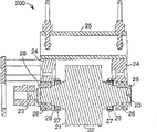
Fig. 2 is the front plan view of the anvil roller sub-component of Fig. 1 equipment;
Fig. 3 is the cutaway view along this anvil roller sub-component of the 3-3 line intercepting of Fig. 2;
Fig. 4 be from the front plan view of the anvil roller sub-component of the amplification of the same perspective view of Fig. 2;
Fig. 5 is the cutaway view along this anvil roller sub-component of the 5-5 line intercepting of Fig. 4;
Fig. 6 is the cutaway view along this anvil roller sub-component of the 6-6 line intercepting of Fig. 4;
Fig. 7 is the perspective view that the soldering tip of Fig. 1 equipment is installed sub-component;
Fig. 8 is the front plan view that the soldering tip of Fig. 7 is installed sub-component;
Fig. 9 is the cutaway view that sub-component is installed along this soldering tip of the 9-9 line intercepting of Fig. 8;
Figure 10 is the front plan view of soldering tip assembly, and its soldering tip by Fig. 7 to Fig. 9 is installed sub-component and kept;
Figure 11 is the cutaway view along this soldering tip assembly of the 11-11 line intercepting of Figure 10;
Figure 12 is the perspective view of the soldering tip-anvil portion gap adjustment sub-component of Fig. 1 equipment;
Figure 13 is the side plan view of soldering tip-anvil portion gap adjustment sub-component of Figure 12;
Figure 14 is the side plan view of the soldering tip lifting sub-component of Fig. 1 equipment;
Figure 15 is the front plan view of the soldering tip lifting sub-component of Figure 14;
Figure 16 is the cutaway view of soldering tip lifting sub-component of the 16-16 line intercepting of Figure 15;
Figure 16 A is the optional embodiment of soldering tip lifting sub-component, and it is similar to the view of Figure 16;
Figure 16 B is another optional embodiment of soldering tip lifting sub-component, and it is similar to the view of Figure 16;
Figure 17 is the front plan view of clamping (nip) sub-component of Fig. 1 equipment;
Figure 18 is the side plan view of the clamping sub-component of Figure 17;
Figure 19 illustrates the one exemplary embodiment of the simplification of soldering tip assembly.
The specific embodiment
As mentioned above, the present invention relates to the various improvement of ultrasonic bonding and method.This improvement can connect or uses with rotary-type ultrasonic bonding with the continuous ultrasound wave soldering, the anvil portion of this rotary-type ultrasonic bonding and soldering tip one of them or both rotations.Generally speaking, this improvement relate to the gap that is used for measuring better, detect and control between soldering tip and the anvil portion and motion various structures.
Various optional embodiment are described below, and this optional embodiment has the feature that can combine with other embodiment or use separately.For example, the equipment with free degree of minimizing is described with the rotary ultrasonic wave device, wherein anvil portion and soldering tip both rotations.Provide the feature of the free degree of minimizing can be included in for example soldering tip rotation equally and in the fixing equipment of anvil portion.As another example, the permanent plant that the method that is used to utilize the resonant frequency feedback monitoring and regulate the gap between anvil portion and the soldering tip utilizes soldering tip and the both of anvil portion to fix is described.Monitoring and the feature of regulating the gap are included in the slewing equally, as another example, are used for fixing the permanent plant that the method in the gap between soldering tip and the anvil portion utilizes soldering tip and the both of anvil portion to fix and are described.The feature that the gap is set can be included in the slewing equally.
The schematic diagram of simplifying
Below, Figure 19 is illustrated in the embodiment of the simplification of the installation system shown in Fig. 1-Figure 18, is described below.For the conceptual understanding to system is provided, the system of Figure 19 has saved the details that can see in Fig. 1-18.Corresponding to the purpose of the discussion of Figure 19 is to make the reader briefly understand the outstanding feature of this installation system and need not to make the reader to be absorbed in the details that is occurred in the discussion about Fig. 1-18.
As can be seen from Figure 19, this system comprises soldering tip 1900 and anvil portion 1902.The gap separates soldering tip 1900 and anvil portion 1902.This anvil portion 1902 is installed in the housing 1904 that is fixed in ground.Anvil portion 1902 rotates freely around its longitudinal axis 1906 by means of the ball bearing 1908 that is arranged between this anvil portion 1902 and the housing 1904.Owing to be installed in the structure that is fixed in ground, around the rotation of its longitudinal axis 1906, anvil portion 1902 does not have other frees degree except that aforesaid.
Soldering tip 1900 is installed in the framework 1910, and ball bearing 1912 allows soldering tip around its longitudinal axis 1914 rotations.Connector 1916 connects two and half frameworks 1910.This connector 1916 is connected in translation device (translator) 1918 by pivot 1920.Therefore, framework 1910, connector 1916 and soldering tip 1900 can wind axis (this axis extends into out the paper) rotation that is formed by this pivot 1920.
This translation device 1918 makes it have the single degree of freedom by the structural constraint of being fixed in ground: it can move along the vector perpendicular to the longitudinal axis 1906 of anvil portion 1902.Therefore, by means of being fixed in translation device 1918, framework 1910, connector 1916 and soldering tip 1900 can move along aforementioned vector.In other words, soldering tip 1900 (with framework 1910, connector 1916) can move forward towards anvil portion 1902, or returns from anvil portion 1902.
Therefore, the installation system of Figure 19 only allows two frees degree of soldering tip 1900 location.Soldering tip 1900 can move or retreats from it towards anvil portion 1902.This free degree is connected in translation device 1918 and possible by housing 1910, and this translation device is constrained to along a direction and moves.And the longitudinal axis 1914 of soldering tip 1900 can wind perpendicular to the rotation of the axis of the longitudinal axis 1906 of anvil portion 1902, and this free degree is by pivot 1920 and possible.
On each component function of system shown in Figure 19 corresponding to the parts that exist in the system shown in Fig. 1 to 18.Anvil portion 1902 is corresponding to using the anvil portion shown in the Reference numeral 21 among Fig. 2 and Fig. 3.Anvil portion 1902 be installed in wherein housing 1904 corresponding among Fig. 2 and Fig. 3 with the structure shown in Reference numeral 24 and 25 (be that anvil portion 21 is installed in in the structure shown in the Reference numeral 24 and 25, therefore make them be similar to housing 1904 among Figure 19).
Soldering tip 1900 is corresponding to using the soldering tip shown in the Reference numeral 42 among Figure 11.Soldering tip 1900 be installed in wherein framework 1910 corresponding among Fig. 7 with the structure shown in the Reference numeral 32.And connector 1916 is corresponding to using the structure shown in the Reference numeral 31 (that is, the structure shown in the Reference numeral 31 connects two and half frameworks 32, therefore makes it be similar to connector 1916) among Fig. 7.Soldering tip 190 is laid thereon ball bearing 1912 corresponding to (that is, combination installed part 43,44 and 45 allows soldering tips 42 to rotate in the mode that is suitable for vibrating body with the combination installed part shown in the Reference numeral 43,44 and 45 among Figure 11.Although the expression of the simplification of Figure 19 is if be placed on the ball bearing and will cause damage to it such as the vibrating body of soldering tip.Therefore need combination installed part 43,44 and 45).
Threaded fastener 1924 and 1926 is corresponding to using cam shown in the Reference numeral 50 among Figure 12 and Figure 13.In other words, cam 50 is placed on the cam follower 27 (shown in Figure 3) that is connected in framework 24,25, and anvil portion 21 is installed on this framework 24,25, distance when therefore rotating between change soldering tip 42 and the anvil portion 21 and/or the longitudinal axis of soldering tip 42 orientation.
Considering under the situation that this system of its details and feature occurs, about remaining discusses relevant with disclosing of the one exemplary embodiment of the system that is used to install ultrasonic brazing unit among Fig. 1 to Figure 18.
By the free degree control gap that reduces
With reference to figure 1, Fig. 1 illustrates rotating welding assembly 100.Rotating welding assembly 100 comprises the feature of restriction soldering tip with respect to the anvil portion free degree, therefore, controls gap and motion between soldering tip and the anvil portion preferably in welding process.
Fig. 2 and Fig. 3 provide the detail drawing about anvil parts 200, and anvil parts 200 comprises the anvil roller 21 with roller surface 22 and roll neck 23.Anvil roller 21 can be any suitable roller, for example die roll, knurling rolls, print roller or welding rolls.Anvil portion bearing block 24 is installed on anvil portion framework 25.Anvil roller 21 utilizes accurate bidirectional ball 26 bearings to install and bearing block 24.Anvil roller 21 is configured to rotate around axis, and the preferred axial longitudinal extension is by the center of roller 21.Bearing lock nut 28 with two-way bearing to keeping together and on roll neck 23.Anvil parts 200 also comprises two cam follower bearing assemblies 27 that are installed on the anvil roller neck 23.These cam follower bearing assembly 27 usefulness locking nuts 29 remain on the roll neck 23.
One of feature of the present invention is to move anvil parts 200 transverse to width of cloth material slightly, and this mobile being called transverse to width of cloth material " is sidelong and puts (side-lay) ".To Fig. 6, Fig. 4 to Fig. 6 illustrates the other view of the anvil roller assembly 200 that is supported by side plate 17 with reference to figure 4.Anvil roller 21 is installed on the tie-rod 18 by this way and is installed on side plate 17, makes anvil roller 21 to rotate around the longitudinal axis.In this embodiment, bearing block 24 is supported by tie-rod 18.Anvil roller 21 is fixed in tie-rod 18 by shaft clamping device M1.When clamping device M1 is in releasing orientation.Anvil roller assembly 200 for example with being connected in handle 81 threaded bars 80, can move with respect to side plate 17.Threaded excellent bar (bar) 82 is fixed in side plate 17, and bearing 83 is connected on one of them bearing block on 24.
Fig. 7 illustrates soldering tip installation component 300, and it comprises installation frame 31, bearing block 32, soldering tip drive motors 19, such as the soldering tip drive unit of belt 34.And soldering tip-anvil portion gap adjustment assembly 500.Fig. 8 and Fig. 9 illustrate other features and other views of soldering tip installation component 300.
When soldering tip installation component 300 was installed in the installation component 100, guiding of the slit M2 (as shown in figure 15) in the side plate 17 and permission soldering tip installation component 300 moved as shown in Figure 1.Specifically, the surperficial M3 of the 36 contact side plates 17 of the surface on bearing block 32; Preferably, at least a portion of bearing block 32 is engaged in the slit M2.In certain embodiments, surface 36 is cylindrical surfaces, though this is not main.
Will recognize that all rigid objects have six-freedom degree.Above-described feature has been eliminated four frees degree.
Two available frees degree of remainder be along Y-axis translational motion (towards with leave anvil portion) and rotatablely moving along X-axis.The both sides that the combination of these two frees degree makes the gap between soldering tip 30 and the anvil portion can be independent of soldering tip 30 are regulated.
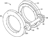
Figure 10 and Figure 11 illustrate soldering tip assembly 400, and it comprises soldering tip 42, combination installed part 43, horn bearings ring 44, horn bearings 45 and horn drive sprocket 46.(it is disclosed in the United States Patent (USP) 6 of Gopal Haregoppa for shown soldering tip 42 and combination installed part 43,786, in No. 384, by with reference to its whole contents is incorporated into this) be some kinds may structures one of them, but this structure is preferred in this embodiment.
Figure 12 and Figure 13 illustrate horn gap or soldering tip-anvil portion gap adjustment assembly 500.Assembly 500 comprises first and second cams 50 and the driven wheel 51 that is connected in this cam.The periphery M5 that the inner periphery M6 of cam is placed on assembly 300 goes up (Fig. 7).Gap between surface M5 and the M6 can rotate cam 50 around the Z axle.
In use, outer cam surface 50a is processed into the generation linear function, h=A θ, and wherein h is total rising of cam, θ is the anglec of rotation of this cam, and A is a constant.In a preferred embodiment, cam rotates the rising that 300 degree cams 50 produce 0.100 inch (about 2.5mm).This provides the degree of regulation (every approximately degree 0.0076mm) of 3/10000 inch of every degree.
Figure 14 illustrates soldering tip lifting assembly 600, and it is used for moving with respect to side plate 17, raises usually and reduces soldering tip installation component 300.When cam face 50a contacted the Cam Follower 27 of anvil parts 200, the mobile of installation component 300 stopped.
With reference to Figure 14, soldering tip lifting assembly 600 comprises the lifting frame 60 that is fixedly connected to side plate 17.What be connected in this lifting frame 60 is bellows 61, and this bellows configuration becomes according to hope to expand and contraction.In use, 61 pairs of soldering tip installation components 300 of compression bellows apply power, to push assembly 300 to anvil roller 21; Other force producer such as linear actuators, pneumatic cylinder, hydraulic cylinder can selectively use.As previously mentioned, soldering tip installation component 300 has two residue frees degree.One is the translational motion along Y-axis, and one is along X (θ
x) axle rotation (Figure 14).
Figure 15 and Figure 16 illustrate the other view of soldering tip lifting assembly 600.In this embodiment, have having of pivot clearance gear-driven seven bar link gears and be used to control the rotation of soldering tip installation component 300 with respect to side plate 17 and installation frame 31.This linkage comprises pitman arm 62, pivotal arm 63, pivotal axis 64, gear 65 and the hinge connector 66,67 of connection.When bellows 61 promotes soldering tip installation component 300, the end of two pivotal arms 63 of pitman arm 62 risings of connection, because two arm transmissions together, it rotates the amount that equates.If very close to each other at pivot fitting 66,67, soldering tip installation component 300 will only vertically move, and rotary freedom X (θ
X) will be eliminated.But because joint 66,67 comprises the gap, so rotation amount allows.
Figure 16 A and 16B illustrate with soldering tip installation component 300 with more basic power mode and have gear-driven seven bar link gear 600A.With reference to figure 16A, in this embodiment, connecting rod (link) the 1st, ground.Link gear 600A comprises the 62A of lever arm repeatedly, pivotal arm 63A, the pivotal axis 64A of connection, and hinge connector 66A, 67A.The end of the pivotal arm 63A that the pitman arm 62A that connects raises at joint 67A, because two arm 63A transmissions together, arm 63A rotates the amount that equates.
Pivotal arm 63A is two two linkages (binary link) that are connected in ground and are connected in pitman arm 62A respectively via joint 64A and 67A.Pivotal arm 63A also interconnects with gear joint.The ratio of this gear joint is 1: 1.Pitman arm 62 also is two linkages that are connected in pivotal arm 63A and are connected in installation frame 31A respectively via swivel joint 67A and 66A.Installation frame 31A is the three-link mechanism that is connected in arm 62A and is connected in sliding seat M11 with pivot fitting 67A and M12.Sliding seat M11 is connected in ground and installation frame 31A with joint M10 and M12.The motion of sliding seat M11 control installation frame 31A makes installation frame 31A have only translation and rotary freedom.
Also can be in the gap in the joint by using the slit shown in Figure 16 B, with clearance control/limits angular motion θ
XRealize.In Figure 16 B, link gear 600B comprises the pitman arm 62B of connection, pivotal arm 63B, pivotal axis 64B and hinge connector 66B, 67B.Hinge connector 66B comprises the slit that the play movement is provided.If L is the distance between the joint 66B, C is the play movement, and the anglec of rotation α of Yun Xuing is provided by following formula so
In a preferred embodiment, C equals 0.03 inch, and L is 11.88 inches, so α is 0.3 degree.
This gap is chosen to or via hole, or slit, and perhaps other make rotation that the gap between soldering tip 42 and the anvil portion is changed, and make gap and process variation (processvariation) to regulate.But this gap is not too big down to not preventing or forbidding that the soldering tip installation also correctly stops on the cam 50.
Figure 17 and 18 illustrates clamping (nip) assembly 700.Clamp assembly comprises pinch roll 71, clamp arm 72, pivotal axis 73, clamping cylinder 74 and cylinder back shaft 75.
A kind of optional exemplary weld assembly is shown among Figure 1A as equipment 100A.Be similar to the equipment 100 of Fig. 1, equipment 100A has a plurality of sub-components.Being shown among Figure 1A is anvil parts 200A, the soldering tip assembly 400A that comprises anvil roller 21, and soldering tip lifting assembly 600A.Be shown in the side plate 17A in addition among Figure 1A.The soldering tip assembly is utilized sheet spring M13 and M14 in a kind of optional method of two frees degree.Equipment 100A comprises sheet spring 13M, usually at least two couples of sheet spring 14M.Every couple of sheet spring M14 is connected in different bearing block 32 and different side plate 17A.
Based on reducing the available free degree so that better control the welding equipment in the gap between anvil portion and the soldering tip, total anvil roller 21 or other rotatable tool roll that comprise with first axle, with the installation system that is used to support anvil roller 21, make that it can be around its first axle rotation.This installation system is configured such that 21 of anvil rollers have two additional degrees of freedom, this first each additional degrees of freedom is along the translational motion perpendicular to this first axle, and second additional degrees of freedom is around the rotatablely moving of second axis, and this second axis is simultaneously perpendicular to the direction of this first axle and this first additional free degree.Xian Zhi range of movement makes the stable distance between this anvil portion and the soldering tip like this.
When reading and understand the process of aforementioned usefulness usefulness control ultrasonic welding system, those of ordinary skill in the art can understand, the clearance control of system can pass through to measure the operating frequency of this soldering tip, and adjusting for example is used to control the pressure in this gap and realizes then.For any soldering tip geometry, comprise the geometry of linear soldering tip and rotary horn, concrete equation can draw or determines by test.
Only the mode with explanation has provided above-mentioned various embodiment and should not be interpreted as limitation of the present invention.Those skilled in the art is easy to recognize, does not break away under the situation of spiritual essence of the present invention and scope, does not imitate one exemplary embodiment described herein and application, can carry out various modifications and variations to the present invention described herein.These modifications and variations propose in the claims.
Claims (17)
1. equipment that is used to contact the width of cloth material of random length comprises:
Rotatable tool roll (42) with first axle;
Be used to support the installation system (100,300) of this rotatable tool roll, make it to rotate, and make that this rotatable tool roll only has two additional frees degree around this first axle,
This first additional free degree is along the translational motion perpendicular to the direction of this first axle,
This second additional free degree is around the rotatablely moving of one second axis, and this second axis is simultaneously perpendicular to the direction of this first axle and this first additional free degree;
Be adjacent to the anvil portion that this installation system is installed; With
Be used to be limited in the device of the peak exercise in this second additional free degree.
2. equipment as claimed in claim 1, wherein this installation system (100,300) comprising:
Framework with two side plates (17), each side plate have area supported and slit are wherein arranged,
A pair of support component (32), each is suitable for engaging this tool roll by this way, makes this tool roll (42) rotate freely, and wherein each support component comprises:
Slidably the slipper of one of engagement slot (17A) and
Supporting part (38) with the curved surface that is engaged in this area supported.
3. equipment as claimed in claim 1, wherein this installation system comprises
Framework with two side plates,
A pair of support component, each is suitable for engaging this tool roll by this way, make this tool roll rotate freely and
At least two pairs of sheet springs (M13), the every pair of sheet spring be connected in different in a plurality of support components one with a plurality of side plates in different one.
4. equipment as claimed in claim 1 also comprises force producer (61), and it is arranged to this installation system is applied power, so that promote this tool roll (42) towards this anvil roller.
5. equipment as claimed in claim 4, wherein this force producer is selected from following one group: bellows (61), linear actuators, pneumatic cylinder and hydraulic cylinder.
6. equipment as claimed in claim 1, wherein this restraint device is to have gear-driven seven bar link gears (62-67).
7. equipment as claimed in claim 4, wherein this tool roll is a wave welding head of ultrasonic wave, and wherein this equipment also comprises the ultrasonic energy source that is connected in this tool roll.
8. equipment as claimed in claim 4, wherein this tool roll is selected from following one group: die roll, knurling rolls, print roller and welding rolls.
9. equipment as claimed in claim 7 also comprises: be arranged to provide according to the frequency of the ultrasonic energy that sends from the welding soldering tip frequency sensor of signal, wherein
This force generating apparatus is regulated distance between this anvil portion and this tool roll in a predefined manner according to this signal.
10. equipment as claimed in claim 2, wherein at least a portion of this curved surface is a cylindrical surface.
11. equipment as claimed in claim 2, wherein at least a portion of this curved surface is a sphere curved surface.
12. equipment as claimed in claim 2 also comprises:
The anvil portion (21) that contiguous this installation system is installed;
Be installed in the first pair of bearer ring (26) in this anvil portion; With
Second pair of bearer ring, each of this second pair of bearer ring is installed on one of support component, makes
Each of first pair of bearer ring can contact one of them of this second pair of bearer ring by this way: limit the minimum range between this anvil portion and this tool roll.
13. a method of handling the width of cloth material of random length comprises:
Be provided for supporting the installation system of rotatable tool roll, make it and to make that this rotatable tool roll only has two additional frees degree around its first axle rotation,
This first additional free degree is along the translational motion perpendicular to the direction of this first axle,
This second additional free degree is around the rotatablely moving of one second axis, and this second axis is simultaneously perpendicular to the direction of this first axle and this first additional free degree;
The rotatable tool roll that will have first axle is installed in this installation system;
Contact this width of cloth material so that handle this width of cloth material with this tool roll;
Anvil roller is set is adjacent to this tool roll; And
Be provided for being limited in the device of the peak exercise in this second additional free degree.
14. method as claimed in claim 13, wherein this contact procedure comprises with this anvil roller and this tool roll and contacts this width of cloth material simultaneously.
15. method as claimed in claim 14, wherein this tool roll is a wave welding head of ultrasonic wave, and wherein this method also comprises the step of vibrating this wave welding head of ultrasonic wave with ultrasonic frequency.
16. method as claimed in claim 15, wherein this installation system comprises:
Framework with two side plates, each side plate have area supported and slit are wherein arranged,
A pair of support component, each is suitable for engaging this tool roll by this way, makes this tool roll rotate freely, and wherein each support component comprises
Slidably the slipper of one of engagement slot and
Supporting part with the curved surface that is engaged in this area supported.
17. method as claimed in claim 13, wherein this restraint device is to have gear-driven seven bar link gears.
Applications Claiming Priority (2)
| Application Number | Priority Date | Filing Date | Title |
|---|---|---|---|
| US64097905P | 2005-01-03 | 2005-01-03 | |
| US60/640,979 | 2005-01-03 |
Publications (2)
| Publication Number | Publication Date |
|---|---|
| CN101094761A CN101094761A (en) | 2007-12-26 |
| CN100586703C true CN100586703C (en) | 2010-02-03 |
Family
ID=36218610
Family Applications (1)
| Application Number | Title | Priority Date | Filing Date |
|---|---|---|---|
| CN200580045835A Active CN100586703C (en) | 2005-01-03 | 2005-12-29 | Method and device for controlling clearance between welding head of ultrasonic welding system and hammering part |
Country Status (10)
| Country | Link |
|---|---|
| US (1) | US7690548B2 (en) |
| EP (1) | EP1833659B1 (en) |
| JP (1) | JP2008526514A (en) |
| KR (1) | KR101197995B1 (en) |
| CN (1) | CN100586703C (en) |
| AR (1) | AR053535A1 (en) |
| BR (1) | BRPI0518538B1 (en) |
| MX (1) | MX2007007979A (en) |
| TW (1) | TWI436880B (en) |
| WO (1) | WO2006074031A1 (en) |
Cited By (1)
| Publication number | Priority date | Publication date | Assignee | Title |
|---|---|---|---|---|
| CN107708975A (en) * | 2015-06-29 | 2018-02-16 | Sig技术股份公司 | Processing for package sleeve, the especially purposes of the equipment of ultrasonic bonding and the equipment |
Families Citing this family (30)
| Publication number | Priority date | Publication date | Assignee | Title |
|---|---|---|---|---|
| RS52603B (en) | 2006-05-11 | 2013-04-30 | Indag Gesellschaft für Industriebedarf mbH & Co. Betriebs KG | Device for ultrasonic welding |
| ES2354498T3 (en) * | 2008-04-18 | 2011-03-15 | Cavanna S.P.A. | DEVICE TO SUPPORT CONTRARROTATIVE ELEMENTS. |
| DE102009002296A1 (en) | 2009-04-09 | 2010-10-14 | Robert Bosch Gmbh | Apparatus and method for processing a packaging material by means of ultrasound |
| DE102009002298A1 (en) * | 2009-04-09 | 2010-10-14 | Robert Bosch Gmbh | Device for processing a packaging material by means of ultrasound |
| DE102009002295A1 (en) * | 2009-04-09 | 2010-10-14 | Robert Bosch Gmbh | Device for processing a packaging material by means of ultrasound |
| MX2011009814A (en) * | 2009-04-27 | 2011-09-29 | Sca Hygiene Prod Ab | Method and system for creating an apertured web-shaped material. |
| US9005799B2 (en) | 2010-08-25 | 2015-04-14 | Lg Chem, Ltd. | Battery module and methods for bonding cell terminals of battery cells together |
| DE102010043089A1 (en) * | 2010-10-29 | 2012-05-03 | Robert Bosch Gmbh | Sealing jaw for sealing a packaging material by means of ultrasound |
| US9034129B2 (en) | 2011-01-13 | 2015-05-19 | Lg Chem, Ltd. | Ultrasonic welding system and method for forming a weld joint utilizing the ultrasonic welding system |
| US8821149B2 (en) * | 2011-05-05 | 2014-09-02 | Kimberly-Clark Worldwide, Inc. | Web treatment apparatus having center bearer ring |
| US8640760B2 (en) * | 2011-08-19 | 2014-02-04 | Lg Chem, Ltd. | Ultrasonic welding machine and method of aligning an ultrasonic welding horn relative to an anvil |
| US8695867B2 (en) | 2011-08-31 | 2014-04-15 | Lg Chem, Ltd. | Ultrasonic welding machine and method of assembling the ultrasonic welding machine |
| ITTO20130524A1 (en) * | 2013-06-26 | 2014-12-27 | Soremartec Sa | ASSEMBLY GROUP |
| CN104148798B (en) * | 2014-09-04 | 2016-05-04 | 芜湖新宝超声波设备有限公司 | Automobile instrument panel ultrasonic welding machine |
| WO2016059688A1 (en) * | 2014-10-15 | 2016-04-21 | 日産自動車株式会社 | Ultrasonic bonding device and ultrasonic bonding method |
| US10259165B2 (en) | 2015-04-01 | 2019-04-16 | Aurizon Ultrasonics, LLC | Apparatus for fabricating an elastic nonwoven material |
| MX2018004499A (en) * | 2015-10-29 | 2018-07-06 | Kimberly Clark Co | Ultrasonic anvil having low transmissibility. |
| US10537479B2 (en) | 2016-09-15 | 2020-01-21 | Curt G. Joa, Inc. | Dual bonder |
| CN106298685B (en) * | 2016-09-29 | 2019-01-04 | 中国船舶重工集团公司第七一九研究所 | A kind of electronic chip packaging structure using ultrasonic bonding |
| JP7050768B2 (en) | 2016-09-30 | 2022-04-08 | デューケイン アイエーエス エルエルシー | Equipment for manufacturing elastic non-woven materials |
| BR112020003831B1 (en) | 2017-08-25 | 2023-03-07 | 3M Innovative Properties Company | ADHESIVE ARTICLE FOR MOUNTING AN OBJECT ON A SURFACE |
| US11517977B2 (en) * | 2017-09-15 | 2022-12-06 | Tech-Sonic, Inc. | Dual cam servo weld splicer |
| US11426992B2 (en) | 2018-10-04 | 2022-08-30 | Curt G. Joa, Inc. | Closed-loop adjustment system and method for gap control and leveling of ultrasonic devices |
| JP2022528511A (en) | 2019-03-22 | 2022-06-14 | デューケイン アイエーエス エルエルシー | Equipment for manufacturing elastic non-woven fabric materials |
| CN109848541B (en) * | 2019-03-27 | 2024-02-09 | 晋江海纳机械有限公司 | Continuous ultrasonic welding machine |
| WO2021212130A1 (en) * | 2020-04-17 | 2021-10-21 | Curt G. Joa, Inc. | Closed-loop multi-axis adjustment system and method for gap control and leveling of ultrasonic devices |
| US11311960B2 (en) * | 2020-08-10 | 2022-04-26 | Fabrisonic Llc | High-efficiency welding assembly for use in ultrasonic additive manufacturing |
| CN114643715A (en) * | 2020-12-17 | 2022-06-21 | 沈阳新松机器人自动化股份有限公司 | Mask machine edge sealing tooth welding mechanism |
| CN114799468A (en) * | 2021-01-28 | 2022-07-29 | 无锡鼎加弘思饮品科技有限公司 | Ultrasonic welding device and ultrasonic welding test equipment |
| CN115740725B (en) * | 2022-12-28 | 2023-09-15 | 苏州泽术智能自动化科技有限公司 | Be used for full-automatic bonding tool clamping device of bonding tool installation |
Family Cites Families (17)
| Publication number | Priority date | Publication date | Assignee | Title |
|---|---|---|---|---|
| US4553461A (en) * | 1982-10-12 | 1985-11-19 | Magna-Graphics Corporation | Rotary web processing apparatus |
| DE3501631A1 (en) * | 1985-01-19 | 1986-07-24 | VEGLA Vereinigte Glaswerke GmbH, 5100 Aachen | DEVICE FOR COLLECTING GLASS PANES WITH A PLASTIC FILM |
| JP2705423B2 (en) * | 1992-01-24 | 1998-01-28 | 株式会社日立製作所 | Ultrasonic bonding equipment and quality monitoring method |
| US5552013A (en) * | 1994-06-29 | 1996-09-03 | Kimberly-Clark Corporation | Apparatus and method for rotary bonding |
| JP2837126B2 (en) * | 1996-01-23 | 1998-12-14 | 三菱重工業株式会社 | Single-facer gluing adjustment method and apparatus |
| AU2688397A (en) * | 1996-05-29 | 1998-01-05 | Alusuisse Technology & Management Ag | Method and laminating mechanism for producing a laminated composite |
| DE19803638A1 (en) | 1998-02-02 | 1999-08-05 | Kuesters Eduard Maschf | Device for processing a material web with ultrasound |
| JP3600431B2 (en) | 1998-03-09 | 2004-12-15 | 三島 大二 | Ultrasonic welding equipment |
| JP3290632B2 (en) * | 1999-01-06 | 2002-06-10 | 株式会社アルテクス | Ultrasonic vibration bonding equipment |
| US6287403B1 (en) * | 2000-02-15 | 2001-09-11 | Kimberly-Clark Worldwide, Inc. | Support system for rotary function rolls |
| US6540854B2 (en) * | 2000-11-30 | 2003-04-01 | Kimberly-Clark Worldwide, Inc. | Load cell closed loop control for rotary ultrasonic bonding apparatus |
| JP3597476B2 (en) | 2001-01-16 | 2004-12-08 | 三島 大二 | Ultrasonic vibration horn in ultrasonic welding equipment |
| US6634539B2 (en) | 2001-09-21 | 2003-10-21 | 3M Innovative Properties Company | Adjustable-gap rotary ultrasonic horn mounting apparatus and method for mounting |
| US7998528B2 (en) * | 2002-02-14 | 2011-08-16 | Massachusetts Institute Of Technology | Method for direct fabrication of nanostructures |
| EP1447204A1 (en) * | 2003-02-12 | 2004-08-18 | Telsonic Holding AG | Apparatus and process for working of elements |
| JP4297715B2 (en) * | 2003-03-31 | 2009-07-15 | ユニ・チャーム株式会社 | SEALING DEVICE AND SEALING METHOD USING THE SEALING DEVICE |
| US6786384B1 (en) * | 2003-06-13 | 2004-09-07 | 3M Innovative Properties Company | Ultrasonic horn mount |
-
2005
- 2005-12-29 MX MX2007007979A patent/MX2007007979A/en not_active Application Discontinuation
- 2005-12-29 BR BRPI0518538A patent/BRPI0518538B1/en not_active IP Right Cessation
- 2005-12-29 KR KR1020077017857A patent/KR101197995B1/en active IP Right Grant
- 2005-12-29 WO PCT/US2005/047347 patent/WO2006074031A1/en active Application Filing
- 2005-12-29 JP JP2007549610A patent/JP2008526514A/en not_active Withdrawn
- 2005-12-29 EP EP05855841.2A patent/EP1833659B1/en active Active
- 2005-12-29 CN CN200580045835A patent/CN100586703C/en active Active
- 2005-12-29 US US11/321,265 patent/US7690548B2/en active Active
-
2006
- 2006-01-02 TW TW095100123A patent/TWI436880B/en not_active IP Right Cessation
- 2006-01-03 AR ARP060100009A patent/AR053535A1/en not_active Application Discontinuation
Cited By (1)
| Publication number | Priority date | Publication date | Assignee | Title |
|---|---|---|---|---|
| CN107708975A (en) * | 2015-06-29 | 2018-02-16 | Sig技术股份公司 | Processing for package sleeve, the especially purposes of the equipment of ultrasonic bonding and the equipment |
Also Published As
| Publication number | Publication date |
|---|---|
| KR101197995B1 (en) | 2012-11-05 |
| US7690548B2 (en) | 2010-04-06 |
| BRPI0518538B1 (en) | 2016-12-20 |
| JP2008526514A (en) | 2008-07-24 |
| EP1833659A1 (en) | 2007-09-19 |
| KR20070104904A (en) | 2007-10-29 |
| WO2006074031A1 (en) | 2006-07-13 |
| AR053535A1 (en) | 2007-05-09 |
| US20060144904A1 (en) | 2006-07-06 |
| BRPI0518538A2 (en) | 2008-12-02 |
| EP1833659B1 (en) | 2017-09-20 |
| MX2007007979A (en) | 2007-08-22 |
| CN101094761A (en) | 2007-12-26 |
| TW200639043A (en) | 2006-11-16 |
| TWI436880B (en) | 2014-05-11 |
Similar Documents
| Publication | Publication Date | Title |
|---|---|---|
| CN100586703C (en) | Method and device for controlling clearance between welding head of ultrasonic welding system and hammering part | |
| US7059103B2 (en) | Sealing apparatus and manufacturing process of soft article having sealed portion | |
| US8783324B2 (en) | Device for processing a packing material using ultrasound | |
| EP1455956B1 (en) | Control of processing force and process gap in rigid rotary ultrasonic systems | |
| KR100935043B1 (en) | Ultrasonic welding device and method for mounting a rotary ultrasonic welding horn to the ultrasonic welding device | |
| JP2008526514A5 (en) | ||
| US6537403B1 (en) | Nip adjustment for a rigid ultrasonic bonder or processor | |
| JP3307741B2 (en) | Robot welding gun unit | |
| JP4956029B2 (en) | Friction stir welding apparatus and friction stir welding method | |
| US6186210B1 (en) | Heat sealing device | |
| US20070164078A1 (en) | Spin welding device | |
| JP2578746Y2 (en) | Paper press mechanism of paper-pving plotter | |
| JPH0410020Y2 (en) | ||
| JPH0755055A (en) | Rounding device of piping and pushing method of piping inner peripheral surface | |
| JP2969485B2 (en) | Paper press mechanism of paper-pving plotter | |
| JPH054488A (en) | Pressing mechanism for paper moving plotter paper | |
| JPH0747180B2 (en) | Inner surface processing equipment for pneumatic tube | |
| JPH11320112A (en) | Electric gun | |
| JPH0771557A (en) | Direct acting conversion/friction driving device | |
| JP2000210748A (en) | Expansion device for metal shaft stock | |
| JPH02115423U (en) | ||
| JPS60141374A (en) | Automatic welding device |
Legal Events
| Date | Code | Title | Description |
|---|---|---|---|
| C06 | Publication | ||
| PB01 | Publication | ||
| C10 | Entry into substantive examination | ||
| SE01 | Entry into force of request for substantive examination | ||
| C14 | Grant of patent or utility model | ||
| GR01 | Patent grant |