CN100577544C - Sheet-processing apparatus, sheet-processing method, and image-forming system - Google Patents
Sheet-processing apparatus, sheet-processing method, and image-forming system Download PDFInfo
- Publication number
- CN100577544C CN100577544C CN200710126391A CN200710126391A CN100577544C CN 100577544 C CN100577544 C CN 100577544C CN 200710126391 A CN200710126391 A CN 200710126391A CN 200710126391 A CN200710126391 A CN 200710126391A CN 100577544 C CN100577544 C CN 100577544C
- Authority
- CN
- China
- Prior art keywords
- sheet material
- cutting
- pattern
- cutting quantity
- unit
- Prior art date
- Legal status (The legal status is an assumption and is not a legal conclusion. Google has not performed a legal analysis and makes no representation as to the accuracy of the status listed.)
- Active
Links
Images


Classifications
-
- G—PHYSICS
- G03—PHOTOGRAPHY; CINEMATOGRAPHY; ANALOGOUS TECHNIQUES USING WAVES OTHER THAN OPTICAL WAVES; ELECTROGRAPHY; HOLOGRAPHY
- G03G—ELECTROGRAPHY; ELECTROPHOTOGRAPHY; MAGNETOGRAPHY
- G03G15/00—Apparatus for electrographic processes using a charge pattern
-
- B—PERFORMING OPERATIONS; TRANSPORTING
- B65—CONVEYING; PACKING; STORING; HANDLING THIN OR FILAMENTARY MATERIAL
- B65H—HANDLING THIN OR FILAMENTARY MATERIAL, e.g. SHEETS, WEBS, CABLES
- B65H45/00—Folding thin material
- B65H45/12—Folding articles or webs with application of pressure to define or form crease lines
- B65H45/28—Folding in combination with cutting
-
- B—PERFORMING OPERATIONS; TRANSPORTING
- B65—CONVEYING; PACKING; STORING; HANDLING THIN OR FILAMENTARY MATERIAL
- B65H—HANDLING THIN OR FILAMENTARY MATERIAL, e.g. SHEETS, WEBS, CABLES
- B65H29/00—Delivering or advancing articles from machines; Advancing articles to or into piles
- B65H29/50—Piling apparatus of which the discharge point moves in accordance with the height to the pile
- B65H29/51—Piling apparatus of which the discharge point moves in accordance with the height to the pile piling by collecting on the periphery of cylinders
Abstract
A sheet-processing apparatus (10) which enable users to easily set the cutting amount of sheets according to the intended purpose of use. A folding unit folds the sheets. A cutting unit cuts (900) off ends of the folded sheets. A setting unit sets details of processing of the sheets to be executed at least by the center-folding unit (500) and the cutting unit (900). The setting unit is capable of selecting a first cutting-amount setting mode in which a cutting amount is set using a cutting width of the at least one end, and a second cutting-amount setting mode in which the cutting amount is set using a sheet size which the sheets should have after being cut. The setting unit sets the cutting amount in a selected one of the first cutting-amount setting mode and the second cutting-amount setting mode, when setting details of processing of the sheets to be executed by the cutting unit.
Description
Technical field
The present invention relates to a kind of the have plate materials processing device of cutting function, a kind of sheet-processing method and a kind of imaging system.
Background technology
Traditionally, known a kind of imaging system, this imaging system have the equipment for after-treatment (plate materials processing device) that is connected to such as the imaging device of duplicator and laser printer, have thus be used to bind the ability of operating under the stapling mode of processing.Under this stapling mode, be used for staple bookbinding processing, and be used for folding processing at sheet material center pleated sheet at sheet material center bookbinding sheet material.
Figure 46 is the view of piling up through the folding sheet material of handling of traditional staple bookbinding and center.Sheet material in bookbinding is piled up, when pile in sheet material quantity big or pile in the thickness of each sheet material when big, pile folding sheet material the opposite end appropriate section interior sheet material with outside do not aim between the sheet material, this has reduced the outward appearance that the sheet material finished is piled up.As solution to this, a kind of equipment for after-treatment has been proposed, it is equipped with the width by using cutter cuts for example to fall several millimeters to cut the cutting function that sheet material is piled up uneven end, to aim at the respective end of sheet material thus, be used to improve the outward appearance of finishing (seeing Japanese kokai publication hei (Kokai) No.2003-341919) of piling up.
And when cutting, uneven partial L is cut off (seeing Figure 46).Therefore, viewpoint from operability, a kind of method of understanding easily for the user is the length of specifying the uneven side piled up from sheet material to cut away, and thereby adopts the method (Japanese kokai publication hei (Kokai) No.2004-210509) of this set cutting quantity traditionally.
Yet, in traditional plate materials processing device, in the following space that still has improvement in some:
Recently, the lengthening size of being longer than the preassigned size is slightly used in beginning in the chopping machine of for example duplicator.When use has the sheet material of this lengthening size,, and in the central area of sheet material, form image with preliminary dimension along the side assurance margin of each sheet material.Sheet material with formation image thereon is used for cutting away margin along the side of sheet material through cutting process.
Thereby the user piles up at the bookbinding sheet material with lengthening size and carries out cutting process, not only is used to cut away uneven part, and is used for cutting away margin along the side of sheet material.
Therefore, for the user who wants to cut away sheet material such as the undesired part of margin, according to the size of images that is formed on the sheet material, produce following problem: when the Cutting Length (cutting width) of specifying from the sheet material end, the user need grasp the size and thereon the size of images to be printed of recording sheet in advance, and then by the calculating and setting cutting quantity.This makes and is easy to error occur in cutting quantity is set, and makes the user discontented.
Summary of the invention
The invention provides and make the user a kind of plate materials processing device of cutting quantity, a kind of sheet-processing method and a kind of imaging system easily are set according to the application target of expection.
In a first aspect of the present invention, a kind of plate materials processing device of handling sheet material is provided, this equipment comprises and is suitable for the center folding unit of heart place pleated sheet therein, be suitable for cutting away folding sheet material at least one end cutter unit and the unit is set, this is provided with the details that the unit is suitable for being provided with the sheet material processing that will pass through center folding unit and cutter unit execution at least, the unit is set can select first cutting quantity that pattern is set and second cutting quantity is provided with pattern, the cutting width that described at least one end of use in the pattern is set at first cutting quantity is provided with cutting quantity, at second cutting quantity sheets of sizes of using sheet material should have in the pattern is set after cutting cutting quantity is set, and when the details that will be handled by the sheet material that cutter unit is carried out is set, the unit is set operates so that the pattern and second cutting quantity to be set at first cutting quantity and be provided with in the pattern and under the selected pattern cutting quantity be set.
By layout, the cutting width of at least one end of using folding sheet material in the pattern is set or the sheets of sizes of using sheet material should have in the pattern is set after cutting at first cutting quantity cutting quantity is set at second cutting quantity according to the plate materials processing device of a first aspect of the present invention.Therefore, the user can easily be provided with cutting quantity according to the application target of expection.Therefore, even in the time will cutting away, cutting quantity is set, to improve operability thus along margin that the side of each sheet material extends with also can preventing user error.
The unit is set at one end to be selected between cut mode and the multiterminal cut mode, at one end in the cut mode, only cut away folding sheet material and the opposite end of folded end that forms by pleated sheet, and in the multiterminal cut mode, cut away a plurality of ends of folding sheet material except folded end, and when having selected an end-grain cutting to cut pattern, the unit is set can be provided with first cutting quantity cutting quantity under the pattern is set, and when having selected the multiterminal cut mode, the unit is set first cutting quantity can be set pattern and second cutting quantity be set cutting quantity under the pattern in the pattern is set.
By the layout of this embodiment of plate materials processing device, cutting quantity can be set cutting quantity under the pattern that matches with selected cut mode in the pattern is set.This has improved the satisfaction of user to treatment facility.
The unit is set is provided with according to the size of sheet material to be processed that first cutting quantity is provided with pattern and second cutting quantity is provided with the cutting quantity under the selected pattern in the pattern.
By layout, can improve the user-operable of equipment according to the plate materials processing device of this embodiment.
When the size of sheet material to be processed is standard size, the unit is set first cutting quantity can be set cutting quantity under the pattern is set, and when the size of sheet material to be processed is the size of lengthening, the unit is set second cutting quantity can be set cutting quantity under the pattern is set.
By layout, can make hardware compatibility have the sheet material of lengthening size according to the plate materials processing device of this embodiment.
Plate materials processing device also can comprise the staple stapling unit, this staple stapling unit is suitable for carrying out the staple bookbinding on a plurality of sheet materials that are stacked on another, and be provided with the unit whether can be provided with in the sheet material center not only carry out the staple bookbinding but also carry out sheet material folding, perhaps only carry out sheet material in the sheet material center folding, and do not carry out the staple bookbinding.
In a second aspect of the present invention, a kind of method of handling sheet material is provided, the step that is provided with that comprises processing details that sheet material is set, according to the processing details that is provided with therein heart place pleated sheet the center folding step and cut away the cutting step at least one place, end of folding sheet material according to the processing details that is provided with, step wherein is set can select first cutting quantity that pattern is set and second cutting quantity is provided with pattern, be provided with in the pattern at first cutting quantity, use the cutting width of at least one end that cutting quantity is set, be provided with in the pattern at second cutting quantity, the sheets of sizes of using sheet material should have after cutting is provided with cutting quantity, and step is set to be comprised: when the details that will be handled by the sheet material that cutter unit is carried out is set, be provided with that first cutting quantity is provided with pattern and second cutting quantity is provided with the cutting quantity under the selected pattern in the pattern.
By the layout of according to a second aspect of the invention method, can obtain and according to a first aspect of the invention the identical advantageous effects that plate materials processing device provided.
In a third aspect of the present invention, a kind of imaging system that comprises imaging device and plate materials processing device is provided, wherein handle the sheet material that forms image by imaging device thereon by plate materials processing device, described imaging system comprises the acceptor unit that is suitable for receiving from the sheet material of imaging device discharge, be suitable for the center folding unit of heart place pleated sheet therein, be suitable for cutting away folding sheet material at least one end cutter unit and be suitable for being provided with the unit that is provided with of details that the sheet material carried out by center folding unit and cutter unit at least handles, this is provided with the unit and can selects first cutting quantity that pattern is set and second cutting quantity is provided with pattern, be provided with in the pattern at first cutting quantity, use the cutting width of at least one end that cutting quantity is set, be provided with in the pattern at second cutting quantity, the sheets of sizes of using sheet material should have after cutting is provided with cutting quantity, and when the details that will be handled by the sheet material that cutter unit is carried out is set, the unit is set operates that first cutting quantity is provided with pattern and second cutting quantity is provided with the cutting quantity under the selected pattern in the pattern to be provided with.
By the layout of according to a third aspect of the invention we imaging system, can obtain and according to a first aspect of the invention the identical advantageous effects that plate materials processing device provided.
Above and other purpose of the present invention, feature and advantage will be from becoming comparatively obvious below in conjunction with the detailed description of accompanying drawing.
Description of drawings
Fig. 1 is the scheme drawing according to the imaging system of first embodiment of the invention;
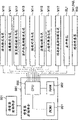
Fig. 2 is the block diagram of controller of the overall operation of control imaging system;
Fig. 3 is the view that the outward appearance of operation is shown;
Fig. 4 is the longitudinal cross-section figure of truing device;
Fig. 5 is the block diagram of truing device control part and connected parts;
Fig. 6 is the longitudinal cross-section figure of trimmer;
Fig. 7 is the birds-eye view of trimmer;
Fig. 8 is the view that is used to illustrate edge cuts;
Fig. 9 is the view that is used to illustrate top and bottom cutting;
Figure 10 is the block diagram of trimmer control part and connected parts;
Figure 11 is the sheet material on-cycle view that is used for illustrating overstepping one's bounds lectotype;
Figure 12 is the sheet material on-cycle view that is used for illustrating the branch lectotype;
Figure 13 is the sheet material on-cycle view that is used for illustrating the branch lectotype, and the state shown in this view is followed the state of Figure 12;
Figure 14 is the sheet material on-cycle view that is used for illustrating second pile of branch lectotype;
Figure 15 is the sheet material on-cycle view that is used for illustrating second pile of branch lectotype, and the state shown in this view is followed the state of Figure 14;
Figure 16 is the sheet material on-cycle view that is used for illustrating second pile of branch lectotype, and the state shown in this view is followed the state of Figure 15;
Figure 17 is the sheet material on-cycle view that is used for illustrating second pile of branch lectotype, and the state shown in this view is followed the state of Figure 16;
Figure 18 is the view that the application model that shows on telltale is selected picture;
Figure 19 is the view that the sheet material box is provided with picture;
Figure 20 is the view that staple bookbinding and cutting are provided with picture;
Figure 21 is the view that cutting is provided with picture;
Figure 22 is the view that cutting quantity is provided with picture;
Figure 23 is the view that cutting quantity is provided with picture;
Figure 24 is the view of the cutting width assigned picture that shows when having selected " cutting width appointment " key;
Figure 25 is the view that the final size that shows when having selected " final size appointment " key is selected picture;
Figure 26 is the view of the final size assigned picture that shows when having selected " being provided with in detail " key;
Figure 27 is the view of the final size assigned picture that shows when having selected " final size appointment " key;
Figure 28 is used for illustrating truing device sheet material on-cycle view under the stapling mode;
Figure 29 is the sheet material on-cycle view that is used for illustrating bookbinding path under the stapling mode;
Figure 30 is the sheet material on-cycle view that is used for illustrating bookbinding path under the stapling mode, and the state shown in this view is followed the state of Figure 29;
Figure 31 is the sheet material on-cycle view that is used for illustrating bookbinding path under the stapling mode, and the state shown in this view is followed the state of Figure 30;
Figure 32 is used to the sheet material on-cycle view that illustrates that stapling mode is following second pile;
Figure 33 is used to second pile sheet material on-cycle view is described that the state shown in this view is followed the state of Figure 32;
Figure 34 is the sheet material on-cycle view that is used to illustrate under the cut mode;
Figure 35 is the sheet material on-cycle view that is used to illustrate under the cut mode, and the state shown in this view is followed the state of Figure 34;
Figure 36 is the sheet material on-cycle view that is used to illustrate under the cut mode, and the state shown in this view is followed the state of Figure 35;
Figure 37 is the sheet material on-cycle view that is used to illustrate under the cut mode, and the state shown in this view is followed the state of Figure 36;
Figure 38 is the diagram of circuit that the cutting set handling is shown;
Figure 39 illustrates the diagram of circuit that is used to be provided with three tunnel processing of cutting, and this three tunnel cutting is carried out in the step S5 of Figure 38;
Figure 40 is the view that is used to be provided with the picture of stapling mode and cut mode, and this picture is presented on according to a second embodiment of the present invention the imaging system;
Figure 41 is the view that shows the final size assigned picture be used to be provided with stapling mode and cut mode;
Figure 42 is the view that shows the cutting width assigned picture be used to be provided with stapling mode and cut mode;
Figure 43 shows that the final size be used to be provided with stapling mode and cut mode selects the view of picture;
Figure 44 is the view that shows the final size assigned picture be used to be provided with stapling mode and cut mode;
Figure 45 is the view that shows the cutting width assigned picture be used to be provided with stapling mode and cut mode;
Figure 46 is the view of piling up through the folding sheet material of handling of traditional staple bookbinding and center.
The specific embodiment
To describe the present invention in detail with reference to the accompanying drawing that the preferred embodiment of the present invention is shown hereinafter now.
Fig. 1 is the view according to the imaging system of the first embodiment of the present invention.Imaging system comprises imaging device 10, truing device 500 and trimmer 900.Imaging device 10 comprises cis 200 and the chopping machine 300 that reads original image.
When each original copy from left to right reads the position by the original copy that moves on pressuring plate glass 102, read the image that scanning element 104 in the position of position reads original copy by remaining on corresponding to the original copy that moves.This read method is commonly called " document-reading method that moves ".More specifically, when original copy read the position through the original copy that moves, the surface of original copy to be scanned was penetrated in the illumination that is used to the lamp 103 of self-scanning unit 104, and was directed into the lens 108 via catadioptre 105,106 and 107 from the light of original copy reflection.The light that passes lens 108 forms image on the imaging surface of imageing sensor 109.
Thereby each original copy is transferred from left to right to read the position through the original copy that moves, and scans thus, reads original copy as the throughput direction of main scanning direction and original copy as sub scanning direction to utilize perpendicular to the direction of original copy throughput direction.More specifically, when original copy reads the position through the original copy that moves, in the sub scanning direction feeding, along the image that main scanning direction delegation reads original copy with meeting delegation, read whole original images thus by imageing sensor 109 at original copy.The original image that reads optically by imageing sensor 109 converts view data to by this imageing sensor, is used to output to the picture signal control part 202 with reference to hereinafter.Carry out predetermined process from the view data of imageing sensor 109 outputs by picture signal control part 202, and be transported to the exposure control part 110 of chopping machine 300 then as vision signal.
Perhaps, original copy can also be transported to the desired location on the pressuring plate glass 102, and original copy is stopped, and make scanning element 104 from left to right scan manuscript to read original copy thus.This read method is exactly so-called " static document-reading method ".Do not using original copy feeder 100 to read under the situation of original copy, at first, the user lifts original copy feeder 100 and original copy is placed on the pressuring plate glass 102, make then scanning element 104 from left to right scan manuscript to read original copy.In brief, when original copy feeder 100 is not used in when reading original copy, carry out static original copy and read.
The exposure control part 110 of chopping machine 300 is based on from the output of the vision signal of cis 200 and regulate laser beam, and the laser beam regulated of output then.Laser beam shines on the photosensitive drums 111 and is scanned by polygonal mirror 110a simultaneously.On photosensitive drums 111, form electrostatic latent image according to laser beam scanned.When carrying out static original copy when reading, exposure control part 110 outgoing laser beams are so that form correct image (non-mirror image).
The electrostatic latent image that forms on photosensitive drums 111 manifests as the developer image by the developer of supplying with from developing apparatus 113.On the other hand, sheet material is from box (sheet material box) 114 or 115, manually sheet feeder 125 or 124 feedings of two-sided transport path, and and the synchronization point of laser beam irradiation beginning be transported between photosensitive drums 111 and the transfer section 116.Be transferred on the sheet material of feeding by transfer section 116 at the developer image that forms on the photosensitive drums 111.Sheet material with the developer image that is transferred on it is transported to photographic fixing part 117, and photographic fixing part 117 by the heating and add laminated sheet with the developer image fixing to sheet material.Through the sheet material of photographic fixing part 117 through baffle plate 121 and distributing roller 118, thereby be discharged to the outside (to truing device 500) of imaging device 10 from chopping machine 300.
When discharging sheet material towards the below, be that the imaging surface of sheet material is when facing down, the sheet material of process photographic fixing part 117 is directed in the upset path 122 by the blocked operation of baffle plate 121 temporarily, subsequently after the tail end process baffle plate 121 of sheet material, sheet material is turned over, and discharges from chopping machine 300 by distributing roller 118.This sheet material pattern of discharging will be called " upset is discharged " hereinafter.When beginning sequentially to form image from leading page, promptly when forming when using the image that original copy feeder 100 reads, maybe when forming from image that computing machine is exported, the discharge of overturning.The sheet material of discharging by overturning is with correct page number sequence stack.
When supplying with such as the hard sheet material of OHP sheet materials and when this sheet material forms image from manual sheet feeder 125, sheet material is not directed in the upset path 122, and thereby by distributing roller 118 towards on be that its imaging surface face is up discharged.
And, when on being provided with the two sides that is used at sheet material, forming the duplex printing pattern of image, sheet material is directed in the upset path 122 by the blocked operation of baffle plate 121, and be transported to two-sided transport path 124 then, subsequently and the synchronization point of laser beam irradiation beginning supplied to once more between photosensitive drums 111 and the transfer section 116.
On the other hand, the sheet material of discharging from chopping machine 300 is sent to truing device 500.Truing device 500 carries out post-processing at the sheet material of discharging from chopping machine 300.And trimmer 900 is used to cut the processing of sheet material end, and described sheet material is bound and folded at the center staple by truing device 500.
Fig. 2 is the block diagram of layout of controller that the overall operation of control imaging system is shown.Controller is mainly formed by cpu circuit part 150, and cpu circuit part 150 is connected to original copy feeder control part 101, cis control part 201, picture signal control part 202, chopping machine control part 301, operation display control section 401 and truing device control part 501.Picture signal control part 202 is connected to external interface (I/F) 209, and this external interface is connected to computing machine 210.And truing device control part 501 is connected to trimmer control part 901.
Original copy feeder control part 101 is controlled original copy feeder 100 drivingly according to the instruction from cpu circuit part 150.Cis control part 201 is gated sweep unit 104, imageing sensor 109 etc. drivingly, and will be transported to picture signal control part 202 from the analog picture signal of imageing sensor 109 outputs.
Picture signal control part 202 will convert digital signal to from the analog picture signal of imageing sensor 109, then on digital signal, carry out various processing, and the digital signal that will handle converts vision signal to, subsequently vision signal is transported to chopping machine control part 301.And, picture signal control part 202 carries out various processing at the data image signal of importing from computing machine 210 via exterior I/F 209, and the digital signal that will handle converts vision signal to, subsequently vision signal is transported to chopping machine control part 301.Operate by the processing that 150 controls of cpu circuit part are carried out by picture signal control part 202.
Chopping machine control part 301 drives exposure control part 110 based on the vision signal that receives.Truing device control part 501 is included in the truing device 500, and with cpu circuit part 150 exchange messages, to control the overall operation of truing device 500 thus.
The information exchange of 401 controls of operation display control section and operation 400 and cpu circuit part 150.Operation 400 comprises a plurality of keys and a display part, and described a plurality of keys are used to dispose the various functions that are used for imaging, and described display part is used to show the information of indication configuration.Operation display control section 401 will output to cpu circuit part 150 corresponding to the key signals of the corresponding operating of key, and show the corresponding informance bar based on the signal from cpu circuit part 150 on the display part.
Fig. 3 is the view that the outward appearance of operation 400 is shown.On operation 400, be furnished with the initiating key 402, the stop key 403 that is used to interrupt imaging operation that are used to begin imaging operation, be used to be provided with input digit comprise 404 to 412 and 414 ten bond number word keyboards, ID key 413, clearing key 415, reset key 416 etc.And operation 400 comprises Liquid Crystal Display (LCD) 420, and this Liquid Crystal Display (LCD) has the touch panel that is arranged on its top, wherein is provided with soft key.
Imaging system according to present embodiment has overstepping one's bounds lectotype, branch lectotype, orders nail branch lectotype (stapling mode), stapling mode etc. as the post-processing pattern.Be provided with or dispose these patterns by carrying out input operation from operation 400.For example, when the post-processing pattern is set, on initial picture, select soft key " sorter " (see figure 3).In response to this selection, on Liquid Crystal Display (LCD) 420, show sorter type selecting picture, and utilize this sorter type selecting picture that the post-processing pattern is set.
Fig. 4 is the longitdinal cross-section diagram of expression truing device 500.Truing device 500 is carried out various post-processings, comprising: sequentially receive the sheet material of discharging from imaging device 10 and with in a pile the processing of the sheet alignment included in, by clasp machine sheet material is piled up tail end and orders the nail of ordering of nail and handle, be used for piling up punching processing, sorting process, non-sorting process and the bookbinding of tail end punching and handle at sheet material.
When will be being wound on Web guide on the buffer roll 505 in overstepping one's bounds routing footpath 521 time, operation be switched baffle plate 511 to peel off the sheet material that is wound onto on the buffer roll 505, it is directed in the overstepping one's bounds routing footpath 521.The sheet material that is directed in the overstepping one's bounds routing footpath 521 is discharged on the sample pallet 701 509 via distributing roller.Centre portion in overstepping one's bounds routing footpath 521 is provided with sheet material and discharges sensor 533.
When will switch baffle plate 510 and switch baffle plate 511 equal inoperation, and sheet material being sent in the buffer path 523 with the state that is wound on the buffer roll 505 being wound on Web guide on the buffer roll 505 in buffer path 523 time.Centre portion at buffer path 523 is provided with buffer path sensor 532, and it is used for detecting the sheet material on the buffer path 523.
In addition, when will be, switch baffle plate 511 inoperation but switch baffle plate 510 operations being wound on Web guide on the buffer roll 505 in sorting path 522 time, peeling off the sheet material that is wound on the buffer roll 505, with Web guide in sorting path 522.
Downstream position in sorting path 522 is provided with and switches baffle plate 542, is used for Web guide in sorting discharge path 524 or bookbinding path 525.The sheet material that is directed in the sorting discharge path 524 is stacked on the intermediate tray (hereinafter referred to as handling pallet) 630 507 via conveying roller.
As required, with pile form be stacked to the sheet material of handling on the pallet 630 and carry out registration process by being located at the aligning parts of handling pallet 630 front sides and rear side, order nail and handle or the like, by distributing roller 680a and 680b are discharged to afterwards and pile up on the pallet 700.
Distributing roller 680b is supported by swing guiding piece 650.Swing guiding piece 650 is swung by unshowned rotary actuator, so that distributing roller 680b contacts with the sheet material top-sheet of piling up on the processing pallet 630.When distributing roller 680b when top-sheet on handling pallet 630 contact, it can be cooperated with distributing roller 680a, piles up towards piling up pallet 700 discharges with the sheet material that will handle on the pallet 630.
Ordering nail handles by clasp machine 601 execution.Clasp machine 601 is configured to and can moves along the rear end of handling pallet 630, make clasp machine 601 to pile up with respect to sheet material throughput direction (direction left to being stacked on the sheet material of handling on the pallet 630, (right-hand end is ordered nail to tail end as shown in Figure 4) as shown in Figure 4).
In addition, the sheet material that is directed in the bookbinding path 525 is transported to bookbinding intermediate tray (hereinafter referred to as stapling tray) 830 via conveying roller to 802.Centre portion in bookbinding path 525 is provided with bookbinding inlet sensor 831.Stapling tray 830 is provided with intermediate calender rolls 803 and sheet material positioning element 816 movably.In addition, anvil 811 is arranged on the position relative with a pair of clasp machine 810, and clasp machine 810 and anvil 811 cooperations come to pile up and order nail and handle being received in sheet material in the stapling tray 830.
Folding roller is to 804 positions that are arranged on clasp machine 810 downstreams, and crowded push part 815 be arranged on folding roller to 804 relative positions.Impel and squeeze push part 815 and pile up outstandingly towards being received in sheet material in the stapling tray 830, like this, sheet material is piled up to be squeezed and is shifted folding roller onto between 804.This makes sheet material be folded in the center.In the present embodiment, maximum collapsible three sheet materials.Folding roller to 804 not only pleated sheet pile up, and the sheet material after will folding is piled up downstream transport.Then, conveying roller is piled up sheet material after folding to 805 and is transferred to the discharge pallet.Discharge sensor 832 and be arranged on the position of conveying roller 804 downstreams.
Fig. 5 is the block diagram of truing device control part 501 and coupled parts.Truing device control part 501 is made of CPU550, ROM551 and RAM552.What link to each other with CPU550 is each motor M1 to M9, inlet sensor 531, comprise that buffer path sensor 532 and sheet material discharge the path sensor of sensor 533, or the like.
Truing device control part 501 is communicated by letter with the cpu circuit part 150 in being located at imaging device 10 via unshowned communication IC, to carry out data exchange, and carry out the various programs that are stored among the ROM551, so that according to the driving of controlling truing device 500 from the instruction of cpu circuit part 150 drivingly.In addition, except imaging device, truing device control part 501 is also communicated by letter with trimmer control part 901 via communication IC (not shown).
Fig. 6 is the longitdinal cross-section diagram of trimmer 900.Fig. 7 is the birds-eye view of trimmer 900.Trimmer 900 receives the sheet material that folds at the center by the bookbinding part (stapling tray 830 and associated components) of truing device 500.At this moment, 805 sheet materials that fall are clipped between the front side alignment parts 910a and back side alignment parts 910b of the receiving unit that is located at trimmer 900 from the conveying roller of truing device, and move towards the center of transport path, then by load-transfer device 902 downstream transport, thereby proofreaied and correct the sheet material displacement that is taken place during through truing device 500 when sheet material.
Load-transfer device is to 902,903,904 and 905 about being provided with accordingly in the transport path in trimmer 900, and every pair of load-transfer device is identical apart from the distance at transport path center, thereby sheet material is transferred when being clipped in up and down between the load-transfer device.
Being arranged between load- transfer device 902 and 903 is cutting mechanism (edge cuts part), and it is used to cut the relative sheet material of folded end that forms with piling up at the center pleated sheet and piles up end (hereinafter referred to as " edge cuts ").Fig. 8 is used for explaining edge cuts.The sheet material (piling up) that is transported to cutting mechanism is resisted against on the edge cuts retainer 911, and makes it stop at cutting position (seeing Fig. 6 and 7).The upper limb cutter 912a that can vertically move is arranged on and the fixing relative position of lower edge cutter 912b, the sheet material that wherein stops to be piled up in the mode between the edge cuts cutter about being interposed in and is stopped, and upper limb cutter 912a decline is carried out edge cuts (seeing position shown in the dotted line among Fig. 8) so that sheet material is piled up.
Edge cuts retainer 911 with respect to load-transfer device 903 with the mode that can vertically withdraw outstanding (symbol among Fig. 6 " a " expression retracted position) so that under the situation of not carrying out edge cuts or after edge cuts with the sheet material downstream transport.In addition, edge cuts retainer 911 can move by on even keel on throughput direction, be used for the sheet material stop position is switched to according to sheets of sizes and fixed position, perhaps be used for being adjusted in the cutting position (position after the symbol of Fig. 6 " b " the expression displacement) that sheet material is piled up.
Piling up the smear metal of downcutting from sheet material is received in the edge cuts smear metal box 915.Upper limb cutter 912a awaits orders at raised position usually, so that do not disturb the conveying (symbol among Fig. 6 " c " expression standby position) of sheet material.
In addition, be provided for cutting mechanism's (top and bottom cutting part) of the end vertical with folded end for the load-transfer device 905 that is arranged on the edge cuts portion downstream.Fig. 9 is used for illustrating top and bottom cutting.Vertical top of fixing, bottom and bottom cutter 921b and 922b are separately positioned on the front side and the rear side of load-transfer device 905.Make movable upper top and bottom cutter 921a and 922a drop to fixing top, bottom and bottom cutter, like this, the sheet material that stops with the state that is clipped between the load-transfer device 905 is subjected to being similar to the top and the bottom cutting (seeing position shown in dotted lines in Figure 9) of edge cuts.
Top and bottom cutter 921a, 921b, 922a and 922b can move transverse to throughput direction, and move according to sheets of sizes, so that regulate cutting position.Piling up the smear metal of cutting away by top and bottom cutting part from sheet material is received in top and the bottom cutting smear metal box 925.When not carrying out the cutting of top and bottom, sheet material is piled up to be transferred under non-stop situation and is with 905 downstream transport.
After passing through between load-transfer device 905, sheet material is piled up to be discharged to and is piled up on the pallet 930.At this moment, be arranged on the big conveying roller 931 that piles up pallet 930 tops and be driven, pile up the sheet material that is discharged from the pallet 930 and pile up to move.In addition, be stacked on the sheet material that piles up on the pallet 930 and piled up also downstream transport thereon, thereby prevented that sheet material from piling up the outlet port that resides in load-transfer device 905.
Figure 10 is the block diagram of trimmer control part 901 and coupled parts.Trimmer control part 901 is made of CPU950, ROM951 and RAM952.What link to each other with CPU950 is respective motors M10 to M17, retainer screw actuator (SL) SL1, path sensor 941,942 and 943, or the like.
Load-transfer device 902a carries motor M10 to link to each other with 902b with reception, so that driven by it.Load-transfer device 903a carries motor M11 to link to each other with 903b with the edge, so that driven by it.Load-transfer device 904a links to each other with vertical delivery pathways motor M12 with 904b, so that driven by it.Load-transfer device 905a carries motor M13 to link to each other with 905b with top and bottom, so that driven by it.Motor M10 to M13 is stepper motor.
In addition, front side alignment parts 910a and back side alignment parts 910b aim at motor M14 and link to each other with receiving, so that driven by it, thereby make them mobile symmetrically and make them outwards mobile when motor M14 reverses towards the center when motor M14 is just changeing.
Edge cuts retainer 911 links to each other with retainer CD-ROM drive motor M16, and its position is controlled by by retainer CD-ROM drive motor M16 it is moved at throughput direction.Retainer CD-ROM drive motor M16 is a stepper motor.In addition, edge cuts retainer 911 is driven and motion up or down by retainer screw actuator SL1.
Top, top and bottom cutter 921a link to each other with top and bottom cutting motor M17, and are driven up or down by the forward or reverse that motor M17 is cut in top and bottom and move, and this is similar to upper limb cutter 912a.
Now, will describe the sheet material in the truing device 500 circulation about each pattern in overstepping one's bounds lectotype, branch lectotype and the stapling mode.Figure 11 is used for explaining the sheet material circulation in the overstepping one's bounds lectotype.When will being used for sheet material, the user discharges the overstepping one's bounds lectotype of pattern when being appointed as wherein a kind of post-processing pattern, the inlet roller to 502, conveying roller to 503 and buffer roll 505 be driven in rotation, like this, the sheet material P that discharges from imaging device 10 is received the truing device 500 and is transferred.
Figure 12 and 13 is used for explaining the sheet material circulation in the branch lectotype.When the user will specify the branch lectotype, the inlet roller to 502, conveying roller to 503 and buffer roll 505 be driven in rotation, like this, the sheet material P that discharges from imaging device 10 is received the truing device 500 and is transferred therein. Switch baffle plate 510 and 511 static, thereby each sheet material P is directed in the sorting path 522 in position shown in Figure 12.
The sheet material P that is directed in the sorting path 522 is directed in the sorting discharge path 524 by switching baffle plate 542, and is discharged on the processing pallet 630 507 by conveying roller.When discharging, the auxiliary tray 670 that projects upwards prevents from conveying roller sagging or return mistakenly to 507 sheet materials of discharging, and has improved the aligning of handling sheet material on the pallet 630.
Being discharged to the sheet material P that handles on the pallet 630 begins to move towards the retainer of handling on the pallet 630 631 by its deadweight.Sheet material P move by accessory for example blade 660 and returning be with 661 auxiliary.When the tail end of sheet material P against living retainer 631 and after this stopped, the sheet material of discharge was aimed at by aligning parts 641.Afterwards, be clipped in distributing roller and pile up discharging operation, be discharged to and pile up on the pallet 700 sheet material is piled up P to carrying out sheet material between 680a and the 680b by sheet material being piled up P.
Each sheet material is piled up from handling pallet 630 and is discharged, and is configured to the state by aligning parts 641 alignings.Like this, sheet material is piled up to be stacked on one pile of form that piles up on another pile and is piled up on the pallet 700, makes the leading page of every pile of sheet material be positioned at the bottom of this pile sheet material, its surface that forms image down, and the page or leaf of back sequentially is stacked on the leading page by page number order.
To illustrate at sheet material P (first part) sheet material (second part) during the time period that begins to be received the form of piling up with sheet material and discharge how to be transferred below.Figure 14,15,16 and 17 is used for explaining the sheet material circulation in the operating process that sorting second sheet material is piled up.
When imaging device 10 is discharged, first page the sheet material P1 that piles up as second sheet material is wound on the buffer roll 505 by the blocked operation that switches baffle plate 510 and (sees Figure 14).When sheet material P1 was transported to apart from buffer path sensor 532 preset distances, buffer roll 505 stopped.
When as the leading page of second page sheet material P2 when inlet sensor 531 has advanced preset distance (seeing Figure 15), buffer roll 505 begins rotation, thereby sheet material P2 is stacked on the sheet material P1.Sheet material P1 and P2 are transported to buffer path 532 (seeing Figure 16) once more, and follow-up sheet material P3 stacks on it.
Be wound on sheet material P1, P2 on the buffer roll 505 and P3 and peel off from buffer roll 505, and be transported in the sorting path 522 with the form that three sheet materials are piled up P and (see Figure 17) by the blocked operation that switches baffle plate 510.At this moment, a pile discharging operation that places the sheet material of handling on the pallet 630 to pile up P is finished, piles up P thereby handle the new sheet material of discharging of pallet 630 preparation receptions.The sheet material of three sheet materials is piled up P and is discharged on the processing pallet 630.
The 4th and follow-up sheet material all are discharged to via sorting path 522 and handle on the pallet, rather than are transported in the buffer path 532 as first part.
About follow-up sheet material conveying operations, second sheet material is piled up to begin to be discharged to and is piled up on the pallet 700, and carrying out operation same as described above, and this processing repeats, thereby the sheet material of predetermined quantity is piled up to be stacked to and piled up on the pallet 700.Should be noted that in the present embodiment three one of sheet materials are stacked on another, this is not restrictive, also can be two or four or more one of multi-disc material be stacked on another.
Figure 18 is that the application model that shows on telltale 420 is selected picture.This application model selects picture to be used for selecting a kind of in the different mode, and by showing from the initial picture switching when selected when be presented at " application model " on the initial picture (see figure 3) as soft key.Select to select any one in " mixing sheet material ", " front cover/insertion ", " indenting ", " bookbinding ", " bookbinding margin ", " frame is wiped ", " sharpening ", " mirror image ", " positive and negative upset " and " displacement " key on the picture in application model.
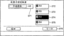
When selecting " bookbinding " key 251, stapling mode starts, and key is shown box that accommodates the recording sheet that will export (sheet material box) that this makes the user can select one of them to be correlated with.Figure 19 is that the sheet material box is provided with picture.Be provided with on the picture at the sheet material box, can select any one in " manually A3 " feeding key, " A4 " feeding key 372, " B5 " key 373, " A3 " feeding key 374, " B4 " key 375.After having chosen the key of the sheet material box that is used to hold sheet material with selected size from this picture, if " next one " key 376 is selected, then this picture is with regard to the picture of the processing that is converted to a sheet material that is used to be provided for to bind (no matter whether carrying out the staple bookbinding) and piles up.Figure 20 represents this picture, i.e. staple bookbinding and cutting are provided with picture.At this moment, if selected stapling mode, carry out folding (hereinafter referred to as " center is folding ") at the center of piling up at sheet material at least, but the user can select whether to carry out the staple bookbinding.Be provided with on the picture in the staple bookbinding, select " carrying out the staple bookbinding " key 351 or " not carrying out the staple bookbinding " key 352.In the example shown, select " not carrying out the staple bookbinding ".
In addition, no matter whether staple is bound, can select whether to cut.No matter the staple bookbinding is provided with how to be provided with,, then to stop setting operation if selected " not carrying out cutting " key 354 and pressed " OK " key 355.Then, this processing turns back to the initial picture (see figure 3), and waits for and press initiating key 402 with beginning imaging operation and post-processing operation.
On the other hand, no matter how the staple bookbinding is provided with,, show that then cutting is provided with picture if selected " carrying out cutting " key 353 and pressed " OK " key 355.Figure 21 represents that cutting is provided with picture.Be provided with in the picture at this, selection is to carry out edge cuts or carry out edge cuts and top and bottom cutting (three tunnel cuttings).
If selected " edge cuts " key 361 and pressed " OK " key 363, shown that then cutting quantity is provided with picture.Figure 22 represents that cutting quantity is provided with picture.This is provided with picture and is used to be provided with Cutting Length x apart from the sheet material end, and can come cutting quantity be set to desirable value by the ten keyboard of operation 400.After being provided with cutting quantity, if press " OK " key 365, termination is set then, and this processing turns back to initial setting up picture (see figure 3).
On the other hand, if selected " three tunnel cuttings " key 362 and pressed " OK " key 363, show that then cutting quantity is provided with picture.Figure 23 represents that cutting quantity is provided with picture.Be provided with on the picture at this, the user can select " cutting width appointment " key 371 or " final size appointment " key 372.In " cutting width appointment ", appointment is apart from the Cutting Length (cutting width) of sheet material end, this is similar to the situation of edge cuts, and in " final size appointment ", be provided with through the sheets of sizes after edge cuts and top and the bottom cutting, the user need not to pay close attention to Cutting Length (cutting width).
Figure 24 represents that the cutting width that has shown is provided with picture when having selected " cutting width appointment " key 371.Similar to the cutting quantity appointment that is used for edge cuts, import cutting quantity (Cutting Length) x of edge side and cutting quantity (Cutting Length) y of top and bottom side by the ten keyboard of operation 400.Figure 25 represents the final size selection picture of demonstration when having selected " final size appointment " key 372.From this picture, can select can the choice criteria size (A4, B5 etc.) key 380 and 381 and can the choice criteria size outside " being provided with in detail " key 382 of required size in any one.As standard size, can between A/B molded dimension and inch molded dimension, switch.If selected wherein a kind of standard size and pressed " OK " key 383, termination then is set, and this processing has turned back to the initial picture (see figure 3).
Figure 26 represents the final size assigned picture of demonstration when having selected " being provided with in detail " key 382.Be provided with on the picture at this, import at the final lengths x that makes progress with the edge cuts related side with at the final lengths y that makes progress with top and bottom cutting related side by the ten keyboard of operation 400.After the input, if press " OK " key 385, termination is set then, and this processing turns back to the initial picture (see figure 3).
Although in the above-described embodiments, if selected edge cuts, then handling automatically, (preferably) proceeds to the cutting width appointment, but this is not restrictively, even when selecting edge cuts and three tunnel to cut any one, the user also can select cutting width to be set or final size is set.In this case, when on picture (seeing Figure 21) is set in cutting, having selected edge cuts, this picture just switches to cutting quantity picture (seeing Figure 23) is set, and switches to the picture of being selected by " cutting width appointment " key 371 or " final size appointment " key 372 then.If selected " cutting width appointments " key 371 this moment, then demonstration is used to be provided with apart from the cutting quantity of the Cutting Length of sheet material end picture (seeing Figure 22) is set.On the other hand, if selected " final size appointment " key 372, show that then being used to that sheet material is set should have the picture of length (final size assigned picture) after cutting.Figure 27 represents the final size assigned picture of demonstration when having selected " final size appointment " key 372.
Figure 28,29,30 and 31 is used to explain sheet material on-cycle view under the stapling mode.When the user specifies stapling mode, drive the inlet roller to 502, conveying roller to 503 and buffer roll 505 rotate, the sheet material P that discharges from imaging device enters truing device 500 and carries therein thus.
Switch baffle plate 510,511 and 542 and be positioned at position shown in Figure 28 when static, sheet material P is directed into bookbinding path 525 from sorting path 522, and is received in the stapling tray 830 802 by conveying roller.Drive intermediate calender rolls 803 and rotate, the front end that is received in the sheet material in the stapling tray 830 is transported to and sheet material positioning element 816 position contacting.At this, the position of sheet material positioning element 816 is configured to be received in the center that the sheet material in the stapling tray 830 piles up can order nail by clasp machine 810.
When the front end of sheet material arrives sheet material positioning element 816 with when this stops, unshowned aligning parts moves perpendicular to the sheet material throughput direction, thereby implements sheet alignment.
Select in the stapling mode processing is set under the situation of " carrying out the staple bookbinding ", when the sheet material of predetermined quantity was received in alignment, the center of clasp machine 810 on sheet material implemented to order nail and operated (after this being called " staple bookbinding ").In being set, the stapling mode processing selects not implement to order the nail operation under the situation of " not carrying out the staple bookbinding ".Should be appreciated that in the present embodiment when selecting " not carrying out the staple bookbinding ", sheet-stacking is handled on the pallet at staple.The sheet material quantity that can be folded in this case, is three.In the present embodiment, staple is handled the bookbinding dish 830 that pallet is specified following state, that is, it is relative to 804 with folding roller that the position of sheet material positioning element 816 is configured to be received in the center that the sheet material in the stapling tray 830 piles up.
Then, reduce sheet material positioning element 816 (referring to Figure 29) and become folding roller to 804 center up to the nail position (center) of ordering that sheet material is piled up.Drive folding roller to 804 and conveying roller rotate 805, make simultaneously and squeeze that push part 815 is outstanding to be pushed away folding roller the sheet material between 804 is piled up (referring to Figure 30) to squeeze.Sheet material is piled up downstream transport and is folded simultaneously, and makes sheet material pile up by conveying roller to 805 to be discharged to trimmer.
To be described in below from beginning to introduce sheet material P (first part) feeding sheets (second part) how during the time period of discharging the sheet material of piling up as sheet material.Figure 32 and 33 is the sheet material circulations that are used to explain that second sheet material is piled up under the stapling mode.
When from imaging device 10 discharges, be similar to the situation that second sheet material is piled up under the branch lectotype, first page the sheet material P1 that piles up as second sheet material is wound on the buffer roll 505 by the blocked operation that switches baffle plate 510.When sheet material P1 was transported to apart from buffer path sensor 532 preset distances, buffer roll 505 stopped.
When as the preceding limb of second page sheet material P2 when inlet sensor 531 is advanced preset distance, buffer roll 505 begins to rotate, thus sheet material P2 is stacked in and makes sheet material P2 with respect to the leading preset distance of sheet material P1 on the sheet material P1.After sheet material P2 was stacked on the sheet material P1, sheet material P1 and P2 were transported to buffer path 532 (referring to Figure 32) once more, and another subsequently sheet material P3 is stacked on sheet material P1 and the P2.
Be wound on sheet material P1, P2 on the buffer roll 505 and P3 and peel off from buffer roll 505, and pile up P as three sheet materials and be transported to (referring to Figure 33) in the sorting path 522 by the blocked operation that switches baffle plate 510.At this moment, finished and be received in the center folding operation that the sheet material in the stapling tray 830 is piled up.In addition, sheet material positioning element 816 is piled up the position of folding operation and is moved to and be used for next sheet material and pile up the position of ordering nail from being used for sheet material formerly.Then, three sheet materials pile up by conveying roller to 802 and intermediate calender rolls 803 be discharged in the stapling tray 830.
The 4th and sheet material subsequently all be discharged in the stapling tray 830 via sorting path 522 and bookbinding path 525 to pile up identical mode with first sheet material.Should be appreciated that in the present embodiment three one of sheet materials are stacked on another, this is not determinate, two or four or more the multi-disc material also can one be stacked on another.
Figure 34 to 37 is used to explain sheet material on-cycle view under the cut mode.The sheet material of being bound and folding by staple in the center under stapling mode is piled up P ' and is begun to discharge from the distributing roller 805 of truing device 500, begins to drive load- transfer device 902a and 902b and rotates.
When the receiving sensor 941 that is set for load-transfer device 902b detects after sheet material piles up the front end of P ', sheet material P ' is transferred through preset distance, and the tail end of piling up P ' when sheet material stops to drive load- transfer device 902a and 902b when dropping on the load-transfer device 902b.At this moment, the front end that sheet material is piled up P ' does not arrive load-transfer device 902a, so sheet material is piled up P ' and is sandwiched in freely and not between load-transfer device 902a and the 902b.Then, aligning parts 910a and 910b implement the centrally aligned of alignment function so that the center and the sheet material of transport path are piled up.When finishing alignment function, drive load- transfer device 902a and 902b once more, thereby the downstream transport sheet material is piled up P '.
When implementing edge cuts, edge cuts retainer 911 is elevated to the position (shown in Figure 34 dotted line) of stretching into transport path from standby position (shown in Figure 34 solid line), and further moves on throughput direction and the cooresponding position of cutting quantity.When path sensor 942 detect pile up the front end of P by the sheet material of load- transfer device 902 and 903 downstream transport after, sheet material P is transferred preset distance, stops load- transfer device 902 and 903 then.At this moment, the front end that sheet material is piled up P contacts with edge cuts retainer 911, and sheet material is piled up P and is in the state of being with 903a and 903b to clamp that is transferred.In addition, at this moment, the tail end that sheet material is piled up P exceeds load-transfer device 902 (referring to Figure 34).
Then, reduce top edge cutter 912a and pile up the tail end of P to cut away sheet material, the smear metal Pt that cuts away is received in the edge cuts smear metal box 915 of being located at the cutter below because deadweight falls.When finishing cutting operation, edge cuts retainer 911 reduces so that vacate transport path.Then, drive load- transfer device 903 and 904 and rotate, thereby further the downstream transport sheet material is piled up P (referring to Figure 35).
On the other hand, when not implementing edge cuts, after piling up P, drive load-transfer device 902,903,904 and 905 and rotate by aligning parts 910 aligning sheet materials, edge cuts retainer 911 remains on the standby position of reduction simultaneously, thereby sheet material is piled up downstream transport and can be parked in the edge cuts part.
When being piled up P by the sheet material of load-transfer device 904 downstream transport and implement top and bottom cutting, after path sensor 943 detected the sheet material front end, sheet material was piled up P and is transferred preset distance, stopped to drive load-transfer device 905 (referring to Figure 36) then.When piling up P by load-transfer device 904 feeding sheets, top and bottom cutter 921 and 922 move to and the cooresponding relevant position of cutting quantity.Then, top and bottom cutter 921a and 922a reduction is piled up top and the bottom of P to cut away sheet material.
The smear metal Ps that cuts away falls so that be received in top and bottom cutting smear metal box 925.After this, when top cutter 921a and 922a are raised, drive load-transfer device 905 and be discharged to and pile up (referring to Figure 37) in the pallet 930 sheet material is piled up P.The front end that sheet material is piled up P arrive be provided for discharging the big conveying roller 931 of pallet before, drive conveying roller 931 and rotate, move to discharging pallet 930 thereby make sheet material pile up P.
Figure 38 is the diagram of circuit of cutting set handling.Be used for the ROM951 of the procedure stores of this processing, and carry out by CPU950 at trimmer control part 901.At first, read in information about relevant setting via truing device control part 501, this is provided with by the soft key on the telltale 420 and sets, and determines whether " to carry out cutting " (step S1) to the stapling mode setting.If " carrying out cutting " is not set, this processing stops at once.
On the other hand,, read in the setting (step S2) of cut mode, determine which (step S3) in edge cuts and three tunnel cuttings to be set to cut mode if be provided with " carry out cutting ".If edge cuts is set, then carry out the setting (step S4) of edge cuts.More specifically, Cutting Length x apart from the sheet material end is set.On the other hand, if three tunnel cuttings are set, then carry out the setting (step S5) of three tunnel cuttings.Use description to be provided with the processing of three tunnel cuttings below.Behind execution in step S4 and S5, stop this operation.
Figure 39 is the diagram of circuit that expression is used for being provided with at step S5 the processing of three tunnel cuttings.In step S11, determine which (referring to the Figure 23) that selects on the picture in cutting width appointment and the final size appointment to be set at cutting quantity.If select cutting width to specify, the cutting quantity y (step S12) that then accepts to be used for the cutting quantity x of edge side and be used for top and bottom side.On the other hand,, then accept standard size or required size (step S13) if in step S11, determine to select final size to specify, and execution in step S12 and S13, this processing is subsequently returned the higher level and is handled.
As so far described, in the imaging system according to first embodiment, the user can easily be provided with cutting quantity according to the application target of expection.Therefore, can reduce the possibility that the user makes a mistake when cutting quantity is set, thereby improve operability.
Then, the second embodiment of the present invention is described.Structure according to the imaging system of second embodiment is identical with the structure of the imaging system of first embodiment.Therefore, only different operations is described, and refers to identical parts, and omit detailed description with identical Reference numeral.
Figure 40 to 45 is used to explain the view that stapling mode and cut mode are set according to second embodiment.Similar with first embodiment, when selecting in application model to select " bookbinding " key 251 in the picture (referring to Figure 18), show the feasible key 441 to 445 (referring to Figure 40) that can select to hold the box of the recording sheet that will export.In the present embodiment, can select the A4 size (sheet material of 210mm * 297mm), the B5 size (sheet material of 257mm * 182mm), A3 size (sheet material of 297mm * 420mm) and the SRA3 size (sheet material of 320mm * 450mm).The SRA3 size is the sheet material of lengthening size, its vertically and side direction longer slightly than A3 size.
Shown in Figure 40 being provided with on the picture, if selected to hold the box of sheet material with selected size, press " next step " key 446, similar with first embodiment, can select independently of one another whether on sheet material is piled up, to implement the staple bookbinding and whether implement edge cuts or three tunnel cuttings (referring to Figure 20 and 21).At this, the staple bookbinding is set howsoever, if select " not carrying out cutting " key 354, and press " OK " key 355, then stop being provided with and handling and return initial picture (referring to Fig. 3).Then, handling wait initiating key 402 is pressed with beginning imaging and post-processing operation.On the other hand, after selecting " carrying out cutting " key 353,, and then press " OK " key 363, then show and the relevant picture of selection size that in picture (referring to Figure 40) is set, is provided with if select " edge cuts " key 361 or " three tunnel cuttings " key 362.
Selecting " SRA3 " key 444 for sheet material and will implement under the situation of edge cuts with lengthening size, show this picture (referring to Figure 41), in this picture, need to import the final size that sheet material should have after cutting by the ten keyboard of operation 400.On this picture, if press " cutting width appointment " key 451, picture switches to the cutting width assigned picture (referring to Figure 42) that is used to specify apart from the Cutting Length of sheet material end.In the cutting width assigned picture, be provided with " final size appointment " key 453, if press this key 453, picture then switches to final size assigned picture (referring to Figure 41).Therefore, the user can specify switching arbitrarily between final size or the given cut length.
On the other hand, if " A3 " key 445 that picture (referring to Figure 40) is gone up the choice criteria sized sheets is set at the sheet material box, if and carried out edge cuts, then picture would switch to the cutting quantity that is used for from the ten keyboard input Cutting Length of operation 400 picture (referring to Figure 42) is set.Equally in this case, can picture be switched to final size assigned picture (referring to Figure 41) by pressing " final size appointment " key 435.
In addition, if select " SRA3 " key 444 and will implement three tunnel cuttings, press " OK " key 363 on the picture (referring to Figure 21) if be provided with in cutting, this picture is switched to final size and selects picture (referring to Figure 43).On final size is selected picture, any key 461 that can choice criteria size (A4, B5 etc.) and 462 and can the choice criteria size outside " being provided with in detail " key 463 of arbitrary dimension.For standard size, can between A/B molded dimension and inch molded dimension, switch.When selecting standard size and pressing " OK " key 464, stop setting and handle being back to initial picture (referring to Fig. 3).
On the other hand, if select " being provided with in detail " key 463, picture switches to final size assigned picture (referring to Figure 44), be used for the final lengths x on the ten keyboard of the operation 400 input direction relevant with edge cuts and the direction of being correlated with top and bottom cutting on final lengths y.Then, after input,, then stop being provided with and handling being back to initial picture (referring to Fig. 3) if press " OK " key 466.
If go up selection " cutting width appointment " key 456 in final size assigned picture (referring to Figure 44), then this picture switches to cutting width assigned picture (referring to Figure 45).On the cutting width assigned picture, when input be used for cutting quantity (Cutting Length) x of edge cuts and be used for the top and cutting quantity (Cutting Length) y of bottom cutting after, if press " OK " key 467, then stop being provided with and handling being back to initial picture (referring to Fig. 3).If go up selection " final size appointment " key 458 in cutting width assigned picture (referring to Figure 45), then this picture switches to final size assigned picture (referring to Figure 43).
Go up choice criteria size A3 and will carry out three tunnel cuttings if in cutting picture (referring to Figure 21) is set, then this picture switches to the cutting width assigned picture (referring to Figure 45) that is used to specify Cutting Length.At this,, the cutting width assigned picture can be switched to final size assigned picture (referring to Figure 43) by selecting " final size appointment " key 458.
As mentioned above, in imaging system according to second embodiment, when the sheets of sizes that is used for cut mode is the lengthening size, picture preferably switches to the picture that is used to be provided with final size, if yet the sheets of sizes that is used for cut mode is a standard size, picture preferably switches to the picture that is used to be provided with Cutting Length.This makes can improve operability.
Be to be understood that the layout that the invention is not restricted to above-mentioned each embodiment, but can in the scope of the function that can realize each embodiment, adopt any suitable arrangement.
For example, the present invention can be applied to system that comprises a plurality of equipment or the unit that is formed by individual equipment.In addition, should be appreciated that imaging device can be not only the chopping machine of initial expection indication, but can adopt facsimile apparatus, or have the multifunction peripheral (MFP) of printing function, copy function, scan function etc. with printing function.
Although the print processing of being carried out by multifunctional equipment is that electrofax is handled in the above-described embodiments, but the invention is not restricted to this, the present invention goes for various print processing, and for example inkjet printing, hot transfer printing printing, hot print, static dump and discharge breakdown are printed.
In addition, according to user's requirement, imaging device can be connected on the optional equipment (being also referred to as annex) of the function of various expansion imaging devices as required.For example, as optional equipment, can mention can feeding or carry the sheet material dish of a large amount of sheet materials.In addition, can mention the tapping and plugging machine that is used to punch with the file sheet material, and the automatic double-sided sheet feeder that is used on the two sides of each sheet material, forming image.In addition, can mention the insertion equipment that is used between sheet material, inserting another sheet material.In addition, can mention and be used for original copy is automatically fed into automatic document feeder on the scanner and the photographic fixing and the equipment for after-treatment that are used for output image is processed into high quality graphic.
Be to be understood that purpose of the present invention also can realize in the following way: provide system or equipment with storage medium, the software program code of realizing the function of arbitrary embodiment in the foregoing description is stored in the described storage medium, and makes the computing machine (or CPU or MUP) of system or equipment read and carry out the program code that is stored in the storage medium.
In this case, realized the function of arbitrary embodiment the foregoing description, and the storage medium of therefore having stored program code has constituted the present invention from the program code self that storage medium reads.
Be used to provide the example of the storage medium of program code to comprise floppy disk (floppy, registered trade mark (RTM)), hard disk, magneto-optical disk, CD-ROM, CD-R, CD-RW, DVD-ROM, DVD-RAM, DVD-RW, DVD+RW, tape, permanent storage card and ROM.Selectively, program can be passed through network download.
In addition, the function that is to be understood that arbitrary embodiment in the foregoing description not only can realize by carrying out the program code that is read by computing machine, and OS (operating system) that can be by making operation on computers etc. implements part or all of practical operation based on the instruction of program code.
In addition, the function that is to be understood that arbitrary embodiment in the foregoing description can realize in the following way: the program code that will from storage medium, read write in the memory device that is arranged on the expansion board of inserting computing machine or be arranged on computing machine bonded assembly expanding element in memory device in, make the CPU that is arranged in expansion board or the expanding element etc. implement part or all of practical operation then based on the instruction of program code.
Although reference example embodiment has described the present invention, should be appreciated that to the invention is not restricted to the disclosed embodiments.The scope of following claim is considered to the wideest explanation so that comprise all this modifications and equivalent structure and function.
The application requires the preceence of the Japanese patent application No.2006-125691 of submission on April 28th, 2006, and therefore its content is included in this by reference.
Claims (7)
1. plate materials processing device of handling sheet material comprises:
The center folding unit is suitable at the center of sheet material pleated sheet;
Cutter unit, at least one end that is suitable for cutting away folding sheet material; And
The unit is set, be suitable for being provided with at least the details that will handle by the sheet material that described center folding unit and described cutter unit are carried out, the described unit that is provided with can select first cutting quantity that pattern is set and second cutting quantity is provided with pattern, be provided with at first cutting quantity and utilize the cutting width of described at least one end that cutting quantity is set in the pattern, at second cutting quantity sheets of sizes of utilizing sheet material should have in the pattern is set after cutting cutting quantity is set, and when the details of the sheet material processing that will carry out by described cutter unit was set, the described unit that is provided with can operate that first cutting quantity is provided with pattern and second cutting quantity is provided with the cutting quantity under the selected pattern in the pattern to be provided with.
2. plate materials processing device as claimed in claim 1, it is characterized in that, the described unit that is provided with is at one end selected between cut mode and the multiterminal cut mode, at one end have only an end of the pleated sheet relative to be cut off in the cut mode with the folded end of sheet material burst, a plurality of ends except folded end of pleated sheet are cut off in the multiterminal cut mode, and when selecting a described end-grain cutting to cut pattern, the described unit that is provided with is suitable for being provided with first cutting quantity cutting quantity under the pattern is set, and when selecting described multiterminal cut mode, the described unit that is provided with is suitable for being provided with first cutting quantity and pattern and second cutting quantity is set cutting quantity under the pattern in the pattern is set.
3. plate materials processing device as claimed in claim 1 is characterized in that, the described unit that is provided with is suitable for size according to sheet material to be processed and is provided with that first cutting quantity is provided with pattern and second cutting quantity is provided with the cutting quantity under the selected pattern in the pattern.
4. plate materials processing device as claimed in claim 3, it is characterized in that, when the size of sheet material to be processed is standard size, the described unit that is provided with is suitable for being provided with first cutting quantity cutting quantity under the pattern is set, and when the size of sheet material to be processed was the lengthening size, the described unit that is provided with was suitable for being provided with second cutting quantity cutting quantity under the pattern is set.
5. as arbitrary described plate materials processing device in the claim 1 to 4, also comprise the staple stapling unit, it is suitable for implementing the staple bookbinding on a plurality of sheet materials that are stacked on another, and
Wherein, described be provided with the unit be suitable for being provided be carry out in the center of sheet material staple bookbinding and sheet material folding both, still only carry out sheet material in the center of sheet material folding and do not implement staple and bind.
6. method of handling sheet material comprises:
Step is set, and it is provided with the details that sheet material is handled;
The center folding step, its according to the processing details that is provided with at the center of sheet material pleated sheet; And
Cutting step, at least one end of cutting away folding sheet material according to the processing details that is provided with,
Wherein, the described step that is provided with can select first cutting quantity that pattern is set and second cutting quantity is provided with pattern, be provided with at first cutting quantity and utilize the cutting width of described at least one end that cutting quantity is set in the pattern, at second cutting quantity sheets of sizes of utilizing sheet material should have in the pattern is set after cutting cutting quantity is set, and when the details of the sheet material processing that will carry out by described cutting step was set, the described step that is provided with comprised and is provided with that first cutting quantity is provided with pattern and second cutting quantity is provided with the cutting quantity under the selected pattern in the pattern.
7. an imaging system comprises imaging device and plate materials processing device, and wherein the sheet material that forms image thereon by imaging device is handled by plate materials processing device, and described system comprises:
Acceptor unit is suitable for receiving the sheet material of discharging from imaging device;
The center folding unit is suitable at the center of sheet material pleated sheet;
Cutter unit, at least one end that is suitable for cutting away folding sheet material; And
The unit is set, be suitable for being provided with at least the details that will handle by the sheet material that described center folding unit and described cutter unit are carried out, the described unit that is provided with can select first cutting quantity that pattern is set and second cutting quantity is provided with pattern, be provided with at first cutting quantity and utilize the cutting width of described at least one end that cutting quantity is set in the pattern, at second cutting quantity sheets of sizes of utilizing sheet material should have in the pattern is set after cutting cutting quantity is set, and when the details of the sheet material processing that will carry out by described cutter unit was set, the described unit that is provided with can operate that first cutting quantity is provided with pattern and second cutting quantity is provided with the cutting quantity under the selected pattern in the pattern to be provided with.
Applications Claiming Priority (2)
| Application Number | Priority Date | Filing Date | Title |
|---|---|---|---|
| JP2006183478 | 2006-07-03 | ||
| JP2006183478A JP4878231B2 (en) | 2006-07-03 | 2006-07-03 | Sheet processing device |
Publications (2)
| Publication Number | Publication Date |
|---|---|
| CN101100252A CN101100252A (en) | 2008-01-09 |
| CN100577544C true CN100577544C (en) | 2010-01-06 |
Family
ID=38544220
Family Applications (1)
| Application Number | Title | Priority Date | Filing Date |
|---|---|---|---|
| CN200710126391A Active CN100577544C (en) | 2006-07-03 | 2007-07-03 | Sheet-processing apparatus, sheet-processing method, and image-forming system |
Country Status (6)
| Country | Link |
|---|---|
| US (1) | US8027630B2 (en) |
| EP (1) | EP1876125B1 (en) |
| JP (1) | JP4878231B2 (en) |
| KR (1) | KR100912769B1 (en) |
| CN (1) | CN100577544C (en) |
| DE (1) | DE602007014144D1 (en) |
Families Citing this family (15)
| Publication number | Priority date | Publication date | Assignee | Title |
|---|---|---|---|---|
| JP2008062307A (en) * | 2006-09-04 | 2008-03-21 | Nisca Corp | Cutting waste recovering method, sheet bundle cutter, bookbinding device and image forming apparatus |
| JP4861215B2 (en) * | 2007-02-28 | 2012-01-25 | キヤノン株式会社 | Sheet processing apparatus and image forming apparatus |
| JP5361351B2 (en) | 2007-12-07 | 2013-12-04 | キヤノン株式会社 | Sheet processing apparatus, image forming apparatus, and image forming system |
| US8894064B2 (en) * | 2008-01-31 | 2014-11-25 | Hewlett-Packard Development Company, L.P. | Inkjet printer accessory |
| JP5409124B2 (en) * | 2009-05-29 | 2014-02-05 | キヤノン株式会社 | Information processing apparatus, control method, and program |
| JP5517744B2 (en) * | 2009-06-16 | 2014-06-11 | キヤノン株式会社 | Sheet processing apparatus and image forming system |
| JP5578958B2 (en) * | 2009-07-08 | 2014-08-27 | キヤノン株式会社 | Sheet processing apparatus and image forming system |
| JP5340218B2 (en) * | 2010-04-22 | 2013-11-13 | キヤノン株式会社 | Printing apparatus and sheet processing apparatus |
| JP5677071B2 (en) * | 2010-12-15 | 2015-02-25 | キヤノン株式会社 | Sheet processing apparatus, sheet processing method, and program |
| JP6057722B2 (en) * | 2012-01-26 | 2017-01-11 | キヤノン株式会社 | Sheet post-processing apparatus and image forming apparatus |
| JP5798997B2 (en) * | 2012-10-10 | 2015-10-21 | 京セラドキュメントソリューションズ株式会社 | Sheet folding apparatus, sheet post-processing apparatus including the same, and image forming apparatus |
| JP2014131829A (en) * | 2012-12-04 | 2014-07-17 | Seiko:Kk | Sheet bundle cutting device and post-processing apparatus using the same |
| JP5849996B2 (en) | 2013-06-18 | 2016-02-03 | コニカミノルタ株式会社 | Paper processing apparatus and image forming system |
| JP2015141332A (en) * | 2014-01-29 | 2015-08-03 | キヤノン株式会社 | Printer, control method of printer, and program |
| USD766347S1 (en) * | 2014-04-29 | 2016-09-13 | Chandra Maurya Pte Ltd | Napkin roller machine |
Family Cites Families (18)
| Publication number | Priority date | Publication date | Assignee | Title |
|---|---|---|---|---|
| JP3181333B2 (en) * | 1990-11-30 | 2001-07-03 | 株式会社リコー | Folding order image forming device |
| JP3533871B2 (en) * | 1997-03-05 | 2004-05-31 | ミノルタ株式会社 | Image forming device |
| US6575446B2 (en) * | 1998-10-06 | 2003-06-10 | Konica Corporation | Image forming apparatus having sheet finisher |
| US6408750B1 (en) * | 1999-06-23 | 2002-06-25 | Fuji Photo Film Co., Ltd. | Printer capable of cutting margins |
| DE60111977T2 (en) * | 2000-02-29 | 2006-06-01 | Konica Corp. | Device for cutting leaves and image forming apparatus with such a device |
| US7177045B2 (en) * | 2001-04-13 | 2007-02-13 | Electronics For Imaging, Inc. | Process and system for mixed page imposition |
| US7137625B2 (en) * | 2002-02-12 | 2006-11-21 | Ricoh Company, Ltd. | Sheet finisher including means for setting cutting position image forming system including the sheet finisher |
| JP3961939B2 (en) | 2002-03-20 | 2007-08-22 | 株式会社リコー | Paper processing apparatus and image forming system |
| JP4143419B2 (en) * | 2003-01-07 | 2008-09-03 | キヤノン株式会社 | Image forming system, sheet post-processing apparatus, cutting and sheet feeding control method |
| JP3832440B2 (en) * | 2003-02-27 | 2006-10-11 | 富士ゼロックス株式会社 | Paper processing device |
| US7207557B2 (en) * | 2003-06-04 | 2007-04-24 | Konica Minolta Business Technologies, Inc. | Image forming system and single-sheet processing machine |
| JP2005088110A (en) * | 2003-09-16 | 2005-04-07 | Konica Minolta Business Technologies Inc | Paper cutting device, its control method, image forming device, and image forming system |
| JP4289456B2 (en) * | 2003-11-12 | 2009-07-01 | 株式会社デュプロ | Bookbinding apparatus and bookbinding pretreatment apparatus |
| US7328893B2 (en) * | 2004-04-20 | 2008-02-12 | Konica Minolta Business Technologies, Inc. | Finisher and image forming apparatus equipped therewith |
| US7523593B2 (en) * | 2005-06-14 | 2009-04-28 | Canon Kabushiki Kaisha | Sheet processing device and image forming device |
| JP4655776B2 (en) * | 2005-06-23 | 2011-03-23 | コニカミノルタビジネステクノロジーズ株式会社 | Booklet creation method, booklet creation system and program |
| JP4533285B2 (en) * | 2005-08-30 | 2010-09-01 | キヤノン株式会社 | Image forming system and power saving control method |
| JP4912166B2 (en) * | 2007-01-24 | 2012-04-11 | キヤノン株式会社 | Printing system and control method thereof |
-
2006
- 2006-07-03 JP JP2006183478A patent/JP4878231B2/en not_active Expired - Fee Related
-
2007
- 2007-07-02 US US11/772,554 patent/US8027630B2/en active Active
- 2007-07-02 DE DE602007014144T patent/DE602007014144D1/en active Active
- 2007-07-02 EP EP07111555A patent/EP1876125B1/en active Active
- 2007-07-03 KR KR1020070066448A patent/KR100912769B1/en active IP Right Grant
- 2007-07-03 CN CN200710126391A patent/CN100577544C/en active Active
Also Published As
| Publication number | Publication date |
|---|---|
| EP1876125A2 (en) | 2008-01-09 |
| EP1876125A3 (en) | 2008-11-05 |
| JP4878231B2 (en) | 2012-02-15 |
| US8027630B2 (en) | 2011-09-27 |
| KR20080003730A (en) | 2008-01-08 |
| DE602007014144D1 (en) | 2011-06-09 |
| US20080122156A1 (en) | 2008-05-29 |
| CN101100252A (en) | 2008-01-09 |
| KR100912769B1 (en) | 2009-08-18 |
| EP1876125B1 (en) | 2011-04-27 |
| JP2008013274A (en) | 2008-01-24 |
Similar Documents
| Publication | Publication Date | Title |
|---|---|---|
| CN100577544C (en) | Sheet-processing apparatus, sheet-processing method, and image-forming system | |
| JP4052324B2 (en) | Paper post-processing apparatus and image forming system | |
| JP4747138B2 (en) | Image forming system and image forming apparatus | |
| JP5464790B2 (en) | Bookbinding system and bookbinding apparatus | |
| JP5361351B2 (en) | Sheet processing apparatus, image forming apparatus, and image forming system | |
| JP5335533B2 (en) | Printing apparatus, printing apparatus control method, and program | |
| JP5421178B2 (en) | Sheet cutting apparatus, sheet post-processing apparatus including the sheet cutting apparatus, and image forming system | |
| JP4546059B2 (en) | Image forming apparatus | |
| US6851666B2 (en) | Image forming and binding system and method | |
| US7926800B2 (en) | Sheet processing apparatus and image forming apparatus | |
| JP4684929B2 (en) | Post-processing apparatus and image forming system | |
| US11685627B2 (en) | Post-processing apparatus and image forming system | |
| JP2009101439A (en) | Cutting device, sheet processor, and image forming device | |
| JP2007084270A (en) | Sheet processing device and image forming device | |
| JP3130507B2 (en) | Image forming apparatus having 2 in 1 mode | |
| US11465873B2 (en) | Post-processing apparatus and image forming system | |
| US10926568B2 (en) | Image forming apparatus | |
| JP4155915B2 (en) | Sheet post-processing apparatus and image forming apparatus | |
| JP2005088110A (en) | Paper cutting device, its control method, image forming device, and image forming system | |
| JP2003073011A (en) | Sheet processing device and image forming device with the same | |
| JPH04368891A (en) | Binding apparatus | |
| JP2000272817A (en) | Sheet processing device and method | |
| JPH04358891A (en) | Bookbinding device | |
| JPH06289674A (en) | Copying device | |
| JPH05105317A (en) | Image forming system |
Legal Events
| Date | Code | Title | Description |
|---|---|---|---|
| C06 | Publication | ||
| PB01 | Publication | ||
| C10 | Entry into substantive examination | ||
| SE01 | Entry into force of request for substantive examination | ||
| C14 | Grant of patent or utility model | ||
| GR01 | Patent grant |