CN100577111C - Method and device for using ultrasound Doppler information to display bloodstream image - Google Patents
Method and device for using ultrasound Doppler information to display bloodstream image Download PDFInfo
- Publication number
- CN100577111C CN100577111C CN200710188523A CN200710188523A CN100577111C CN 100577111 C CN100577111 C CN 100577111C CN 200710188523 A CN200710188523 A CN 200710188523A CN 200710188523 A CN200710188523 A CN 200710188523A CN 100577111 C CN100577111 C CN 100577111C
- Authority
- CN
- China
- Prior art keywords
- intensity
- value
- signal
- doppler
- circuit
- Prior art date
- Legal status (The legal status is an assumption and is not a legal conclusion. Google has not performed a legal analysis and makes no representation as to the accuracy of the status listed.)
- Expired - Fee Related
Links
Images


Abstract
The invention relates to an ultrasound diagnosis technique, in particular to a method and a device of displaying blood flow images by ultrasonic Doppler information. The invention is characterized in that: firstly, ultrasonic impulses are emitted to an interesting direction or an interesting region according to the predetermined repeated frequency, and echo signals returning from the direction or the region are received; secondly, a series of orthogonal composite Doppler difference frequency signals with the sampling volume are extracted from the echo signals; thirdly, the delayed autocorrelation strength of the orthogonal composite Doppler difference frequency signals is calculated; fourthly, the blood flow images are displayed according to the delayed autocorrelation strength. The blood flow images can also be clearly displayed through the ultrasonic Doppler information under the conditions that the signal-noise ratio is low and the transmission power is not increased.
Description
Technical field
The present invention relates to the ultrasonic diagnosis technology, particularly relate to a kind of method and device that utilizes ultrasound Doppler information to display bloodstream image.
Background technology
Existing supersonic blood imaging technique comprises two kinds of fundamental types: color doppler velocity imaging technique and color Doppler power imaging technique.
The color doppler velocity imaging technique occurs that the history in more than 20 year has been arranged.This technology comprises to be obtained in the area-of-interest or the make progress Doppler signal of diverse location of interested parties, and is offset or frequency with the doppler phase that these Doppler signals are assessed each sampling volume.Doppler phase skew or frequency are directly proportional with the speed of blood flow in each sampling volume, and the polarity of skew shows blood flow direction.After doppler signal power reaches certain threshold value, be encoded into colour signal according to the amplitude and the polarity information thereof of skew, overlapping being presented on the structural images can be indicated the having or not of blood flow, speed and direction.
This type is not good enough to the display effect of low speed blood flow; The dependence of angle that shows to blood flow rate; Can not show and the subvertical blood flow of ultrasonic beam; And since the average frequency scope of blood flow doppler signal and the average frequency scope of random noise signal overlap each other, therefore generally need establish one is enough to fully or the approaching power threshold that covers the noise scope fully, have only the Doppler signal that surpasses this threshold value just to be shown, with the appreciable impact of avoiding noise to cause.Therefore, this technology only is applicable to the blood flow doppler signal that shows higher signal to noise ratio.
Color Doppler echocardiography power imaging technique occurs that the history in more than 10 year has also been arranged.This technology is not generally considered the size of blood flow rate, only pays close attention to the intensity of the Doppler signal that is received.Calculate the intensity of the Doppler signal of each sampling volume on a section or the sample line, its colour that is encoded into different brightness is represented.This type does not have dependence of angle, does not have aliasing; Can show well the low speed blood flow and with the subvertical blood flow of ultrasonic beam; Owing to can adopt averaging, show that the sensitivity of blood flow is higher; Also need not to be provided with a complete or approaching power threshold that covers the noise scope fully, that is to say,, can obviously not influence the demonstration of blood flow doppler signal with more high-power value even display noise because its power is lower, is faint in color.But the same with the color doppler velocity imaging technique, have only when the signal to noise ratio of doppler signal power and noise power surpasses to a certain degree, could show blood-stream image distinct, exactly.
Yet in many practical clinical, when detecting through cranium or detecting than deep tissue, the blood flow doppler signal that can receive is usually very weak, even is starkly lower than noise power; In addition, as general ultrasonographic principle, it is as far as possible little to wish to detect used ultrasound intensity, particularly detects sensitive part, during such as positions such as eye, testis, heads.These clinical settings or clinical requirement all may obviously reduce the signal to noise ratio of DOPPLER ULTRASOUND SIGNAL, make existing color Doppler echocardiography imaging technique can not show the distribution of blood flow distinct, exactly.
Summary of the invention
The purpose of this invention is to provide a kind of lower and do not increase the method and the device that also can more clearly utilize ultrasound Doppler information to display bloodstream image under the situation of transmitting power in signal to noise ratio.
The object of the present invention is achieved like this, utilize the method for ultrasound Doppler information to display bloodstream image, comprise step: 1. according to predetermined repetition rate to interested parties to or the region of interest emission ultrasonic pulse, and receive the echo signal that returns in these directions or the zone; 2. from above-mentioned echo signal, extract the compound Doppler beat freque signal of quadrature of a series of sampling volumes; 3. further obtain according to the compound Doppler beat freque signal of the quadrature of sampling volume and postpone self correlation intensity; 4. show blood-stream image according to described delay self correlation intensity.
Described can be by providing the variation of colour signal brightness or the variation of GTG luminance signals according to the variation that postpones self correlation intensity according to postponing self correlation intensity demonstration blood-stream image.
Described step can comprise in addition according to the compound Doppler beat freque signal of the quadrature of sampling volume in 3. further obtains blood flow rate or Doppler frequency information.
Described can be to compare according to postponing self correlation intensity and a preset value according to postponing self correlation intensity level demonstration blood-stream image, if more than or equal to preset value, then further carries out coloud coding according to blood flow rate or Doppler frequency information.
Utilize the device of ultrasound Doppler information to display bloodstream image, which comprises at least: device 3, display unit 4 are calculated by ultrasonic signal transmitting and receiving device 1, Doppler signal extraction unit 2, Doppler signal place; Wherein ultrasonic signal transmitting and receiving device 1 comprises transducer 101, radiating circuit 102, receiving circuit 103 at least; Transducer 101 is electrically connected respectively with radiating circuit 102, receiving circuit 103, radiating circuit 102 is used for providing electricity to drive to transducer 101, make its with predetermined frequency to interested parties to or the region of interest emission ultrasonic pulsative signal, 103 of receiving circuits receive and amplify the echo signal that returns in these directions or the zone; Doppler signal extraction unit 2 extracts the compound Doppler beat freque signal of quadrature from receiving circuit 103 echo signals; I, the Q quadrature composite signal of process mti filter 105 filtered each sampling volume enters Doppler signal place calculation device 3 and handles; Calculate device 3 and comprise self correlation intensity counting circuit 106 at the Doppler signal place, self correlation intensity counting circuit 106 comprises delay autocorrelator 200, intensity- conversion circuit 206a, 206b, and summation translation circuit 207, compound Doppler beat freque signal 1 component of quadrature carries out filtering by mti filter 105a, Q component is undertaken entering in the self correlation intensity counting circuit 106 after the filtering by mti filter 105b, at first postpone auto-correlation processing by postponing autocorrelator 200, obtain the real part A value and the imaginary part B value of the auto-correlation function of the compound Doppler beat freque signal of quadrature, it is characterized in that: real part A value and imaginary part B value respectively with intensity- conversion circuit 206a, 206b is electrically connected, intensity- conversion circuit 206a, 206b is electrically connected with summation translation circuit 207, the output of summation translation circuit 207 is sent into display unit 4 as postponing self correlation intensity C value, and display unit 4 shows blood-stream image according to postponing self correlation intensity C value.
Described intensity- conversion circuit 206a, 206b are respectively the square operation devices.
Described intensity- conversion circuit 206a, 206b are respectively the signed magnitude arithmetic(al) devices.
Calculate device 3 and comprise self correlation intensity counting circuit 106 and blood flow rate calculating device 107 at described Doppler signal place, the real part A value of resulting auto-correlation function and imaginary part B value offer blood flow rate simultaneously and calculate device 107 in the self correlation intensity counting circuit 106, blood flow rate is calculated device 107 and is calculated blood flow rate and self correlation intensity counting circuit 106 resulting delay self correlation intensity C values and offer display unit 4 together and be used to show blood-stream image.
Described summation translation circuit 207 is adders.
Described summation translation circuit 207 comprises an adder 208 and an extracting operation device 209, two inputs of described adder 208 are electrically connected with the outfan of intensity- conversion circuit 206a, 206b respectively, the outfan of adder 208 is electrically connected with the input of extracting operation device 209, and the output of extracting operation device 209 is sent into display unit 4 as postponing self correlation intensity C value.
Described summation translation circuit 207 comprises an adder 208 and a logarithm operation device 210, two inputs of described adder 208 are electrically connected with the outfan of intensity- conversion circuit 206a, 206b respectively, the outfan of adder 208 is electrically connected with the input of logarithm operation device 210, and the output of logarithm operation device 210 is sent into display unit 4 as postponing self correlation intensity C value.
Effect of the present invention: because random noise has no rule, it is very poor to postpone autocorrelation, and the bandwidth of the compound blood flow doppler signal of common quadrature is narrower, has good delay autocorrelation, therefore, adopt technology of the present invention, whether reach threshold value according to the intensity level that postpones auto-correlation function and determine whether display color (or gray scale) blood flow signal, perhaps the coding that utilizes the intensity level that postpones auto-correlation function to carry out colour or gamma characteristic (as brightness) can obviously reduce effect of noise, improves blood flow shows under the low signal-to-noise ratio condition definition and sensitivity.
Another remarkable advantage of the present invention is a method and relatively simple for structure.Because can need not to carry out the power assessments of Doppler signal, its complex structure degree and operand can be lower than existing common color velocity profile doppler imaging device, more economically.
The more important thing is, utilize the technology of the present invention, can under the situation that does not influence the blood flow observation, further obviously reduce ultransonic transmitting power.This also has great value for improving significant points as the supersonic blood inspection of eye, cranium brain position and the safety of monitoring.
Description of drawings
Describe the preferred embodiments of the present invention in detail below in conjunction with the embodiment accompanying drawing.
Fig. 1 is the structured flowchart according to a kind of compuscan of principle construction of the present invention;
Fig. 2 is the structured flowchart that meets a kind of self correlation intensity counting circuit of principle of the present invention;
Fig. 3 is the structured flowchart that meets a kind of translation circuit of suing for peace of principle of the present invention;
Fig. 4 is the structured flowchart that meets the another kind summation translation circuit of principle of the present invention;
Fig. 5 is a kind of basic coloud coding mode sketch map that meets principle of the present invention;
Fig. 6 is the operational flowchart with the corresponding a kind of chromacoder of Fig. 5;
Fig. 7 is the second kind of basic coloud coding mode sketch map that meets principle of the present invention;
Fig. 8 is the operational flowchart with the corresponding a kind of chromacoder of Fig. 7;
Fig. 9 is the third the basic coloud coding mode sketch map that meets principle of the present invention;
Figure 10 is the operational flowchart with the corresponding a kind of chromacoder of Fig. 9.
Among the figure: 1, ultrasonic signal transmitting and receiving device; 2, Doppler signal extraction unit; 3, device is calculated at the Doppler signal place; 4, display unit; 101, transducer; 102, radiating circuit; 103, receiving circuit; 104, quadrature demodulator; 105a, 105b, mti filter; 106, self correlation intensity counting circuit; 107, blood flow rate is calculated device; 108, digital scan converter; 109, chromacoder; 110, display; 200, postpone autocorrelator; 201a, 201b, delay circuit; 202a, 202b, 202c, 202d, mlultiplying circuit; 203, adder; 204, subtractor; 205a, 205b, integrating circuit; 206a, 206b, intensity-conversion circuit; 207, summation translation circuit; 208, adder; 209, extracting operation device; 210, logarithm operation device.
The specific embodiment
Fig. 1 is the structured flowchart according to a kind of compuscan of principle construction of the present invention, and it is that circuit part with existing Ultrasonic Color Doppler Diagnostic system replaces with the circuit block diagram that provides after the content of the present invention.Self correlation intensity counting circuit 106 in figure and the later circuit, its circuit implementation procedure can be with existing as broad as long, yet for enforcement thought of the present invention intactly is described, describe complete as a whole in the following description.
Generally speaking, the present invention comprises ultrasonic signal transmitting and receiving device 1, Doppler signal extraction unit 2, Doppler signal place calculation device 3, display unit 4 at least; Wherein, ultrasonic signal transmitting and receiving device 1 comprises at least: transducer 101, radiating circuit 102, receiving circuit 103, transducer 101 is electrically connected respectively with radiating circuit 102, receiving circuit 103.Transducer 101 can have unit or the two-dimensional array unit of shaking of shaking of the unit of singly shaking, one-dimensional array as required.Radiating circuit 102 be used for predetermined frequency to interested parties to or the region of interest emission ultrasonic pulsative signal, receiving circuit 103 is used to receive the echo signal that returns in these directions or the zone.In the emission phase, radiating circuit 102 provides electric drive signal to transducer 101, makes transducer to body (prior art does not show) transmitted pulse type high-frequency ultrasonic.The unit if transducer 101 employing arrays are shaken, correspondingly in the radiating circuit 102 can comprise an emission acoustic beam and form device (prior art, do not draw), make between the driving signal that offers the unit of respectively shaking and have needed various time delay, thereby can obtain to focus on good acoustic beam, and can be used for the transmit direction of deflection ultrasonic beam.In the take over period, the echo that reflects from body is converted into by transducer 101 and enters receiving circuit 103 after the echo-signal and amplify, and be converted into digital signal (at other embodiments, in receiving circuit 103, can not have the analog-to-digital conversion module, do not carry out analog-to-digital conversion, and the analog quadrature demodulator that directly connects backward provides analogue signal).If transducer 101 comprises is the array unit of shaking, then correspondingly in the receiving circuit 103 can comprise one and receive acoustic beam and form device (prior art, do not draw), it makes from first detected echo signal that respectively shakes and obtains optimum focusing by applying different time delays; And can be in order to the deflection receive direction, the echo signal of the desirable direction of directional reception.
The echo signal of receiving circuit 103 outputs is admitted to Doppler signal extraction unit 2, and Doppler signal extraction unit 2 comprises quadrature demodulator 104 and mti filter 105 at least, and mti filter 105 comprises mti filter 105a and mti filter 105b.Whether the echo signal according to input has been converted into digital signal, and quadrature demodulator 104 can be digital or analog quadrature-phase demodulator (all can adopt prior art).Echo signal is demodulated to its quadrature phase composite signal here, comprises two composition: in-phase component I and quadrature component Q.If analog quadrature-phase demodulator then also comprises thereafter being separately converted to digital signal with analog I, Q component with the demodulation gained by an analog-digital converter (prior art is not drawn).Then digital I, the Q signal sequence of each sampling volume are sent into mti filter 105a and mti filter 105b respectively and are carried out moving-target and show (MTI) filtering, mti filter 105 is equivalent to a high pass filter, be used for each sampling volume of filtering I, Q signal comprised by caused direct current or low frequency noise signals such as blood vessel wall, valve and other organizational interfaces.Through I, the Q complex signal sequence of mti filter 105 filtered each sampling volume, promptly the compound Doppler beat freque signal of its quadrature (at this paper and other documents, also often being called Doppler signal or frequency shift signal for short) enters the Doppler signal place and calculates device 3.
Calculate device 3 and comprise self correlation intensity counting circuit 106 at least at the Doppler signal place.As shown in Figure 2, self correlation intensity counting circuit 106 comprises delay autocorrelator 200, intensity- conversion circuit 206a, 206b, and summation translation circuit 207.Filtered I signal of MT reconnaissance I and Q signal enter and postpone autocorrelator 200, by two delay circuit 201a, 201b, four mlultiplying circuit 202a, 202b, 202c, 202d, adder 203, subtractor 204 and two integrating circuit 205a, 205b postpone auto-correlation processing, obtain the real part A value and the imaginary part B value of auto-correlation function.This processing procedure is quotidian in existing self correlation intensity counting circuit.And an important process is in the present invention, to the real part A value that obtains and imaginary part B value respectively by intensity- conversion circuit 206a, 206b only convert to order of magnitude with real part A value and imaginary part B value relevant and with irrelevant intensity level A ', the B ' of its symbol, two-way intensity level output A ' and B ' enter the conversion of suing for peace of summation translation circuit 207, obtain postponing self correlation intensity C value, the display unit 4 by the back shows blood-stream image according to postponing self correlation intensity C value then.
A kind of preferred implementation of intensity- conversion circuit 206a, 206b is to adopt a square operation device (two inputs that structure is equivalent to a multiplier link to each other with same input signal) respectively; By respectively real part A value and imaginary part B value being carried out square operation, its symbol of cancellation only obtains relevant intensity level A ', the B ' of order of magnitude with real part A value and imaginary part B value.
The another kind of preferred implementation of intensity- conversion circuit 206a, 206b is to adopt a signed magnitude arithmetic(al) device respectively; By the computing of respectively real part A value and imaginary part B value being got its absolute value, its symbol of cancellation only promptly obtains relevant intensity level A ', the B ' of order of magnitude with real part A value and imaginary part B value.
A kind of preferred implementation of summation translation circuit 207 is adders.Its output A ', B ' to intensity- conversion circuit 206a, 206b carries out simple additive operation, gained and export as postponing self correlation intensity C value.
The another kind of preferred implementation of summation translation circuit 207 as shown in Figure 3, comprise adder 208 and extracting operation device 209, output A ', the B ' of 208 pairs of intensity-conversion circuit of adder 206a, 206b carry out additive operation, gained and send into extracting operation device 209, the gained result is as postponing self correlation intensity C value.
The another kind of preferred implementation of summation translation circuit 207 as shown in Figure 4, comprise adder 208 and logarithm operation device 210, output A ', the B ' of 208 pairs of intensity-conversion circuit of adder 206a, 206b carry out additive operation, gained and send into logarithm operation device 210, the logarithm value of gained (such as decibel value) is as postponing self correlation intensity C value.
By above-mentioned real part A value and the imaginary part B value that the delay auto-correlation computation is obtained, through intensity- conversion circuit 206a, 206b, and summation translation circuit 207 obtains the strength indicator of the delay self correlation intensity C value of Doppler signal as blood flow signal, carries out computing compared with direct I, the Q signal to self correlation intensity counting circuit 106 inputs of prior art and obtains doppler signal power value P=I
2+ Q
2Or its range value A=(I
2+ Q
2)
0.5Carry out computing as blood flow signal and obtain doppler signal power value P=I
2+ Q
2Or its range value A=(I
2+ Q
2)
0.5As the strength indicator of blood flow signal, can obviously improve signal to noise ratio, help obtaining fainter blood flow signal, improve the sensitivity that blood flow shows.
Except self correlation intensity counting circuit 106, device 3 is calculated at the Doppler signal place can also preferably include blood flow rate calculating device 107.Blood flow rate is calculated device 107 and can be adopted various prior arts to utilize Doppler signal to calculate blood flow rate.A kind of optimal way is as shown in Figure 1: the real part A value of resulting auto-correlation function and imaginary part B value offer blood flow rate simultaneously and calculate device 107 in the self correlation intensity counting circuit 106; Blood flow rate is calculated device 107 and is calculated blood flow rate (prior art) according to A value and B value, and the delay self correlation intensity C value that calculates with self correlation intensity counting circuit 106 offers display unit 4.
Generally speaking, display unit comprises digital scan converter 108, chromacoder 109, display 110, wherein the effect of digital scan converter 108 is that the data that will obtain according to the ultrasonic scan mode are carried out the scan format conversion process according to the scan mode of display 110 again, send into chromacoder 109 codings again, show blood-stream image by display 110 then.In the above-mentioned order of connection, also can be chromacoder 109 pro-, digital scan converter 108 after, promptly earlier by chromacoder 109 codings, send into digital scan converter 108 then, carry out the scan format conversion process by its scan mode according to display 110.
In the present embodiment, provide three kinds of basic colours or GTG coding mode (not showing anatomical structure only showing blood flow, and need not to show in the simple application of blood flow direction that chromacoder 109 can replace with a gray-coded device).
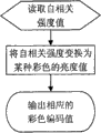
First kind of coded system as shown in Figure 5, similar common colored power-type Doppler, this coding mode is not considered speed, only according to postponing self correlation intensity C value, the brightness of certain color of encoding (such as redness) or GTG: in certain threshold range, self correlation intensity C value is big more, and colour or GTG brightness value are big more.
The concrete steps of first kind of coded system are with reference to figure 6, at first read self correlation intensity C value, then can be red or the brightness value of other certain colors: (noise threshold that C-sets) * 64/ (detection range of setting) by following formula coding, and with the result regular be the integer of 0-63, less than 0 can be regarded as 0, surpass 63 can be regarded as 63 or can be regarded as 0, export corresponding coloud coding value at last.
Second kind of coding mode is similar to existing colored direction type power Doppler coding as shown in Figure 7, promptly determines the kind of color according to the direction of speed, with red, deviates from probe with blue as flow direction probe; Determine the brightness of each color according to postponing self correlation intensity C value, promptly in certain threshold range, it is big more to postpone self correlation intensity C value, and coded color is bright more.
The concrete steps of second kind of coded system are with reference to figure 8, reading speed direction code and postpone self correlation intensity C value at first, judge that then whether velocity attitude is towards probe, the red brightness value of then encoding in this way, otherwise the blue brightness value of just encoding, specifically can be by following formula coding red or blue brightness value: (noise threshold that C-sets) * 64/ (detection range of setting), and with the result regular be the integer of 0-63, less than 0 can be regarded as 0, surpass 63 can be regarded as 63 or can be regarded as 0, export corresponding coloud coding value at last.
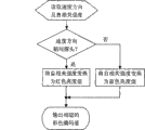
The third coding mode as shown in Figure 9, similar common velocity profile color Doppler coding mode at first will postpone self correlation intensity C value and a threshold value default, that the user can regulate compares, if be lower than threshold value, the colour signal of then not encoding; If more than or equal to threshold value, then further carry out coloud coding: determine the kind of color according to the direction of speed, determine the brightness of color according to the size of speed according to speed.
The concrete steps of the third coding mode are with reference to Figure 10, and at first reading speed information (direction and size) and delay self correlation intensity C value judge then whether to postpone self correlation intensity C greater than noise threshold that if not, the color intensity value is encoded to 0; If, judge further that then whether velocity attitude is towards probe, the red brightness value of then encoding in this way, otherwise the blue brightness value of just encoding, specifically can be by following formula coding red or blue brightness value: blood flow rate absolute value * 64/ Nyquist rate, and with the result regular be the integer of 0-63, export corresponding coloud coding value at last.
On the basis of above 3 kinds of fundamental types, many variations can also be arranged, such as the influence of organizing noise signal for further eliminating, more than a various low speed (or low frequency) threshold value that all can be provided with, the signal that has only speed (or Doppler frequency) to meet or exceed this threshold value is just given and colored (or gray scale) coding.In addition,, can also establish a high speed (or high frequency) threshold value, meet or exceed visibly different color of signal coding of this threshold value, highlight such as green in order to highlight unusual high speed blood flow.
At last, colour (or GTG) signal that coding forms is sent into display 110 after digital-to-analogue conversion, perhaps sending into display 110 laggard line number mould conversions, is shown as two dimension, three-dimensional or M type blood-stream image.
More than though specific embodiment more of the present invention have been described in conjunction with the accompanying drawings, those of ordinary skill in the art can make various distortion or modification within the scope of the appended claims.
Claims (11)
1, utilize the method for ultrasound Doppler information to display bloodstream image, it is characterized in that: 1. according to predetermined repetition rate to interested parties to or the region of interest emission ultrasonic pulse, and receive the echo signal that returns in these directions or the zone; 2. from above-mentioned echo signal, extract the compound Doppler beat freque signal of quadrature of a series of sampling volumes; 3. calculate the delay self correlation intensity of the compound Doppler beat freque signal of described quadrature; 4. show blood-stream image according to described delay self correlation intensity; Wherein, step 3. in by after the compound Doppler beat freque signal of described quadrature being postponed auto-correlation processing and obtaining postponing the real part A value and imaginary part B value of auto-correlation function, further described real part A value and imaginary part B value are carried out again intensity-conversion obtain order of magnitude with real part A value and imaginary part B value relevant and with irrelevant intensity level A ' and the B ' of its symbol, more described intensity level A ' and B ' are sued for peace conversion and obtain described delay self correlation intensity.
2, the method for utilizing ultrasound Doppler information to display bloodstream image according to claim 1 is characterized in that: described is to provide the variation of colour signal brightness or the variation of GTG luminance signals according to the variation that postpones self correlation intensity according to postponing self correlation intensity demonstration blood-stream image.
3, the method for utilizing ultrasound Doppler information to display bloodstream image according to claim 1 is characterized in that: described step also comprises according to the compound Doppler beat freque signal of the quadrature of sampling volume in 3. further obtains blood flowing speed information or Doppler frequency information.
4, the method for utilizing ultrasound Doppler information to display bloodstream image according to claim 3, it is characterized in that: described is to compare according to postponing self correlation intensity and a preset value according to postponing self correlation intensity demonstration blood-stream image, if more than or equal to preset value, then further carry out coloud coding according to blood flowing speed information or Doppler frequency information.
5, utilize the device of ultrasound Doppler information to display bloodstream image, which comprises at least ultrasonic signal transmitting and receiving device (1), Doppler signal extraction unit (2), Doppler signal place calculation device (3), display unit (4); Wherein ultrasonic signal transmitting and receiving device (1) comprises transducer (101), radiating circuit (102), receiving circuit (103) at least; Transducer (101) is electrically connected respectively with radiating circuit (102), receiving circuit (103), radiating circuit (102) is used for providing electricity to drive to transducer (101), make its with predetermined frequency to interested parties to or the region of interest emission ultrasonic pulsative signal, receiving circuit (103) then receives and amplifies the echo signal that returns in these directions or the zone; Doppler signal extraction unit (2) extracts quadrature compound Doppler beat freque signal I and Q from receiving circuit (103) echo signal; I, the Q quadrature composite signal of filtered each sampling volume of process mti filter (105) enters Doppler signal place calculation device (3) and handles; Calculate device (3) and comprise self correlation intensity counting circuit (106) at the Doppler signal place, self correlation intensity counting circuit (106) comprises delay autocorrelator (200), intensity-conversion circuit (206a, 206b), and summation translation circuit (207), I, Q quadrature composite signal enters in the self correlation intensity counting circuit (106), at first postpone auto-correlation processing by postponing autocorrelator (200), obtain the real part A value and the imaginary part B value of the delay auto-correlation function of the compound Doppler beat freque signal of quadrature, it is characterized in that: real part A value and imaginary part B value respectively with intensity-conversion circuit (206a, 206b) be electrically connected, intensity-conversion circuit (206a, 206b) be electrically connected with summation translation circuit (207), the output of summation translation circuit (207) is sent into display unit (4) as postponing self correlation intensity C value; Display unit (4) shows blood-stream image according to postponing self correlation intensity C value.
6, the device that utilizes ultrasound Doppler information to display bloodstream image according to claim 5 is characterized in that: described intensity-conversion circuit (206a, 206b) is the square operation device.
7, the device that utilizes ultrasound Doppler information to display bloodstream image according to claim 5 is characterized in that: described intensity-conversion circuit (206a, 206b) is the signed magnitude arithmetic(al) device.
8, the device that utilizes ultrasound Doppler information to display bloodstream image according to claim 5, it is characterized in that: calculate device (3) and comprise self correlation intensity counting circuit (106) and blood flow rate calculating device (107) at described Doppler signal place, the real part A value of resulting delay auto-correlation function and imaginary part B value offer blood flow rate simultaneously and calculate device (107) in the self correlation intensity counting circuit (106), blood flow rate is calculated device (107) and is calculated blood flow rate and the resulting delay self correlation of self correlation intensity counting circuit (106) intensity C value and offer display unit (4) together and be used to show blood-stream image.
9, the device that utilizes ultrasound Doppler information to display bloodstream image according to claim 5 is characterized in that: described summation translation circuit (207) is an adder.
10, the device that utilizes ultrasound Doppler information to display bloodstream image according to claim 5, it is characterized in that: described summation translation circuit (207) comprises an adder (208) and an extracting operation device (209), two inputs of described adder (208) are electrically connected with the outfan of intensity-conversion circuit (206a, 206b) respectively, the outfan of adder (208) is electrically connected with the input of extracting operation device (209), and the output of extracting operation device (209) is sent into display unit (4) as postponing self correlation intensity C value.
11, the device that utilizes ultrasound Doppler information to display bloodstream image according to claim 5, it is characterized in that: described summation translation circuit (207) comprises an adder (208) and a logarithm operation device (210), two inputs of described adder (208) are electrically connected with the outfan of intensity-conversion circuit (206a, 206b) respectively, the outfan of adder (208) is electrically connected with the input of logarithm operation device (210), and the output of logarithm operation device (210) is sent into display unit (4) as postponing self correlation intensity C value.
Priority Applications (1)
| Application Number | Priority Date | Filing Date | Title |
|---|---|---|---|
| CN200710188523A CN100577111C (en) | 2007-12-29 | 2007-12-29 | Method and device for using ultrasound Doppler information to display bloodstream image |
Applications Claiming Priority (1)
| Application Number | Priority Date | Filing Date | Title |
|---|---|---|---|
| CN200710188523A CN100577111C (en) | 2007-12-29 | 2007-12-29 | Method and device for using ultrasound Doppler information to display bloodstream image |
Publications (2)
| Publication Number | Publication Date |
|---|---|
| CN101214159A CN101214159A (en) | 2008-07-09 |
| CN100577111C true CN100577111C (en) | 2010-01-06 |
Family
ID=39620708
Family Applications (1)
| Application Number | Title | Priority Date | Filing Date |
|---|---|---|---|
| CN200710188523A Expired - Fee Related CN100577111C (en) | 2007-12-29 | 2007-12-29 | Method and device for using ultrasound Doppler information to display bloodstream image |
Country Status (1)
| Country | Link |
|---|---|
| CN (1) | CN100577111C (en) |
Families Citing this family (12)
| Publication number | Priority date | Publication date | Assignee | Title |
|---|---|---|---|---|
| CN101828929B (en) * | 2009-03-11 | 2013-06-19 | 中国科学技术大学 | Vector measurement method of Doppler blood flow velocity by utilizing apparent displacement |
| JP6116853B2 (en) * | 2011-11-30 | 2017-04-19 | 東芝メディカルシステムズ株式会社 | Ultrasonic diagnostic apparatus and image processing method |
| CN103142252B (en) * | 2013-03-21 | 2014-11-12 | 飞依诺科技(苏州)有限公司 | Method and system for realizing automatic deflection of spectral Doppler angle |
| CN103876780B (en) * | 2014-03-03 | 2015-07-15 | 天津迈达医学科技股份有限公司 | High-frequency ultrasonic blood flow gray-scale imaging method and high-frequency ultrasonic blood flow gray-scale imaging device |
| EP2989986B1 (en) * | 2014-09-01 | 2019-12-18 | Samsung Medison Co., Ltd. | Ultrasound diagnosis apparatus and method of operating the same |
| CN106491078B (en) * | 2015-09-07 | 2019-06-25 | 南京理工大学 | Remove the method and device of ordered dither noise in blood-stream image |
| CN107753061B (en) * | 2017-11-03 | 2020-08-04 | 飞依诺科技(苏州)有限公司 | Automatic optimization method and system for ultrasonic elastography |
| CN108433742A (en) * | 2018-03-29 | 2018-08-24 | 东南大学 | A kind of full depth frequency displacement search type transcranial Doppler detection device of portable modulus and method |
| EP3823535A1 (en) * | 2018-07-19 | 2021-05-26 | Mayo Foundation for Medical Education and Research | Systems and methods for removing noise-induced bias in ultrasound blood flow imaging |
| US11109841B2 (en) * | 2018-12-06 | 2021-09-07 | General Electric Company | Method and system for simultaneously presenting doppler signals of a multi-gated doppler signal corresponding with different anatomical structures |
| CN110811688B (en) * | 2019-12-02 | 2021-10-01 | 云南大学 | Ultrafast ultrasonic Doppler blood flow estimation method for multi-angle plane wave repeated compounding |
| CN113081108A (en) * | 2021-03-22 | 2021-07-09 | 华中科技大学同济医学院附属协和医院 | Intelligent navigation hemostatic suture needle and control method thereof |
Citations (4)
| Publication number | Priority date | Publication date | Assignee | Title |
|---|---|---|---|---|
| US4583409A (en) * | 1983-08-24 | 1986-04-22 | Cgr Ultrasonic | Method for measuring the flow parameters of a fluid and device utilizing the method |
| CN1133166A (en) * | 1995-04-10 | 1996-10-16 | 深圳安科高技术有限公司 | Method and instrument of testing rheoencephalogram by Doppler ultrasonic tech. |
| CN1134808A (en) * | 1995-02-06 | 1996-11-06 | 通用电器横河医疗系统株式会社 | Method of displaying ultrasonic images and apparatus for ultrasonic diagnosis |
| CN101081170A (en) * | 2006-06-02 | 2007-12-05 | 株式会社东芝 | Ultrasonic doppler diagnostic apparatus, and method of controlling ultrasonic doppler diagnostic apparatus |
-
2007
- 2007-12-29 CN CN200710188523A patent/CN100577111C/en not_active Expired - Fee Related
Patent Citations (4)
| Publication number | Priority date | Publication date | Assignee | Title |
|---|---|---|---|---|
| US4583409A (en) * | 1983-08-24 | 1986-04-22 | Cgr Ultrasonic | Method for measuring the flow parameters of a fluid and device utilizing the method |
| CN1134808A (en) * | 1995-02-06 | 1996-11-06 | 通用电器横河医疗系统株式会社 | Method of displaying ultrasonic images and apparatus for ultrasonic diagnosis |
| CN1133166A (en) * | 1995-04-10 | 1996-10-16 | 深圳安科高技术有限公司 | Method and instrument of testing rheoencephalogram by Doppler ultrasonic tech. |
| CN101081170A (en) * | 2006-06-02 | 2007-12-05 | 株式会社东芝 | Ultrasonic doppler diagnostic apparatus, and method of controlling ultrasonic doppler diagnostic apparatus |
Non-Patent Citations (6)
| Title |
|---|
| CDFI原理及其质量控制. 李福星,金宝荣,王昌军.数理医药学杂志,第20卷第3期. 2007 |
| CDFI原理及其质量控制. 李福星,金宝荣,王昌军.数理医药学杂志,第20卷第3期. 2007 * |
| 多普勒彩色血流显像. 洪国瑞.中专物理教学,第5卷第2期. 1997 |
| 多普勒彩色血流显像. 洪国瑞.中专物理教学,第5卷第2期. 1997 * |
| 超声多普勒自相关彩色血流成像原理和数字实现技术研究. 张平,刘影,高兴斌.中国医疗器械杂志,第25卷第1期. 2001 |
| 超声多普勒自相关彩色血流成像原理和数字实现技术研究. 张平,刘影,高兴斌.中国医疗器械杂志,第25卷第1期. 2001 * |
Also Published As
| Publication number | Publication date |
|---|---|
| CN101214159A (en) | 2008-07-09 |
Similar Documents
| Publication | Publication Date | Title |
|---|---|---|
| CN100577111C (en) | Method and device for using ultrasound Doppler information to display bloodstream image | |
| US7713204B2 (en) | Image data processing method and apparatus for ultrasonic diagnostic apparatus, and image processing apparatus | |
| JP3406106B2 (en) | Ultrasonic image display method and ultrasonic diagnostic apparatus | |
| US6277075B1 (en) | Method and apparatus for visualization of motion in ultrasound flow imaging using continuous data acquisition | |
| US5285788A (en) | Ultrasonic tissue imaging method and apparatus with doppler velocity and acceleration processing | |
| US6620103B1 (en) | Ultrasonic diagnostic imaging system for low flow rate contrast agents | |
| EP2322951A2 (en) | Adaptively performing clutter filtering in an ultrasound system | |
| EP2555686A2 (en) | Methods and apparatus for ultrasound imaging | |
| WO2012135611A2 (en) | Methods and apparatus for ultrasound imaging | |
| EP1515639A1 (en) | Ultrasonic diagnostic microvascular imaging | |
| US20120078107A1 (en) | Methods and systems for color flow imaging | |
| JP6114823B2 (en) | Ultrasound color flow map for analysis of mitral regurgitation | |
| KR20130075465A (en) | Ultrasound system and method for providing ultrasound image | |
| EP2486421B1 (en) | Ultrasonic anechoic imaging | |
| EP2078494B1 (en) | Noise reduction and aliasing compensation in a doppler mode image | |
| CN201179071Y (en) | Apparatus for displaying bloodstream image with ultrasonic Doppler information | |
| JPH04218143A (en) | Ultrasonic blood current imaging apparatus | |
| US6544184B1 (en) | Imaging with reduced artifacts for medical diagnostic ultrasound | |
| US20120089024A1 (en) | Method of providing three dimensional color doppler image and ultrasound system for implementing the same | |
| JP4312202B2 (en) | Ultrasonic diagnostic apparatus and data processing method of ultrasonic diagnostic apparatus | |
| JP2723458B2 (en) | Ultrasound Doppler diagnostic device | |
| JP4746758B2 (en) | Ultrasound image display by combining enhanced flow imaging in B mode and color flow mode | |
| JPH0549639A (en) | Ultrasonic color doppler diagnostic device | |
| JPH03289947A (en) | Ultrasonic diagnostic device | |
| JP3406096B2 (en) | Ultrasound diagnostic equipment |
Legal Events
| Date | Code | Title | Description |
|---|---|---|---|
| C06 | Publication | ||
| PB01 | Publication | ||
| C10 | Entry into substantive examination | ||
| SE01 | Entry into force of request for substantive examination | ||
| C14 | Grant of patent or utility model | ||
| GR01 | Patent grant | ||
| C17 | Cessation of patent right | ||
| CF01 | Termination of patent right due to non-payment of annual fee |
Granted publication date: 20100106 Termination date: 20121229 |